USER MANUAL SRE 155 Zibro Kamin
Distributed in Europe by:
PVG International B.V.
P.O.Box 96, 5340 AB OSS
LE COMBUSTIBLE APPROPRIÉ
text_image
Zebro
Kumul
A INSTALLATION DU CONVECTEUR
natural_image
Illustration of a hand inserting a rectangular device into a container with a plus symbol (no text or labels)
natural_image
Line drawing of a water pump connected to a battery with a coiled tube (no text or symbols)
natural_image
Two identical oval electronic components with pins, labeled 'vide plein' below (no additional text or symbols)
text_image
temp.
clock
set
20
ave
timer
text_image
temp.
clock
set room
20:15
timer vent.
text_image
temp.
clock
20
ve timer
text_image
set room
E-0
timer vent.
text_image
set room
65 Hr
text_image
set room
CL 05
imer vent
natural_image
Close-up of a car's key and ball on a surface (no text or symbols visible)
natural_image
Illustration of a hand holding a smartphone with a grid screen, no text or symbols visible

natural_image
Cross-sectional diagram of a mechanical device with internal components and an arrow indicating direction (no text or symbols)

natural_image
Diagram of a hand inserting a component into a container with an arrow indicating direction (no text or symbols)

Bouchon de transport
O TRANSPORT
Q CONDITIONS DE GARANTIE
natural_image
Illustration of a hand inserting a rectangular component into a device (no text or symbols visible)

natural_image
Line drawing of a water pump connected to a device with a coiled cable (no text or symbols)
text_image
leer volt
E
text_image
temp.
clock
set
20
ave
timer
text_image
temp.
clock
set room
20:15
e timer vent.
text_image
set room
E-0
timer vent.
text_image
set room
65 Hr
timer vent
text_image
set room
CL 05
imer vent.

natural_image
Close-up of a key icon on a curved surface (no text or symbols)
text_image
Timer Event.
natural_image
Hand holding a grid device with a label 'M' (no text or symbols on the device itself)

text_image
Brennstofffilter
N

natural_image
Diagram of a hand pouring liquid into a container with a downward arrow, alongside a small inset image of a bowl (no text or symbols)
Transportverschluß
natural_image
Illustration of a hand pressing down on a battery holder with a switch, next to an open device (no text or symbols visible)
natural_image
Line drawing of a water pump connected to a battery, showing internal components and wiring (no text or symbols)
natural_image
Technical line drawing of two electronic components labeled Tom Fuld and E, with no readable text or symbols beyond labels.
text_image
temp.
clock
set
20
ave
timer
text_image
temp.
clock
set room
20:15
re timer vent.
text_image
temp.
clock
20
ve
timer
H: Kontrollampen TIMER angiver, at TIMER funktionen er aktiveret.
text_image
set room
E-0
timer vent.
text_image
set room
65 Hr
text_image
set room
CL 05
timer ○ vent
natural_image
Close-up of a car's side panel with a key icon and a light sphere (no text or symbols)
text_image
10
vent. fuel
text_image
mer vent.
natural_image
Hand holding a small electronic device with a grid-patterned screen, no visible text or symbols
natural_image
Diagram of a hand inserting a plug into a container with an arrow indicating direction (no text or symbols)
Transportprop

N OPBEVARING (SLUT PÅ FYRINGSSÆSONEN)
natural_image
Illustration of a hand inserting a plug into a battery into a control panel (no text or symbols visible)
natural_image
Line drawing of a water pump connected to a battery with a sensor (no text or symbols)
text_image
temp.
clock
set
20
ave
timer
text_image
temp.
clock
set room
20:15
re timer vent.
text_image
set room
E-0
timer vent.
text_image
set room
65 Hr
text_image
set room
CL 05
limer vent

natural_image
Close-up of a car's key and ball on the roof (no text or symbols visible)
natural_image
Illustration of a hand inserting a grid into a device labeled M (no text or symbols on the device itself)
natural_image
Technical diagram of a mechanical assembly with no visible text or symbols
J USO CORRECTO DE LA FUNCION 'SAVE'
natural_image
Diagram of a hand inserting a component into a housing, showing a downward arrow (no text or symbols present)

Tapón de transporte
Congratulations with your purchase of the Zibro Kamin, the number one brand among movable heaters. You have purchased a first-class quality product, which will serve you for many years to come. This, of course, provided you use the heater correctly. Please read these Directions for Use first, to ensure maximum lifetime for your Zibro Kamin.
Your heater comes with a 24-month manufacturer's warranty on all defects in material or workmanship.
We wish you much warmth and comfort with your Zibro Kamin.
Yours sincerely,
PVG International b.v.
Customer Service Department
1 READ THE DIRECTIONS FOR USE FIRST.
2 IN CASE OF ANY DOUBT, CONTACT YOUR ZIBRO KAMIN DEALER.
3 BEFORE YOU START READING, FOLD OUT THE LAST PAGE.
▶ ▶ ▶ ▶ ▶ ▶ ▶ ▶
GENERAL DIRECTIONS FOR USE
Below you will find the main steps to be taken for using your Zibro Kamin. For more details, please refer to the MANUAL (pages 45 ff.).
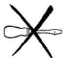
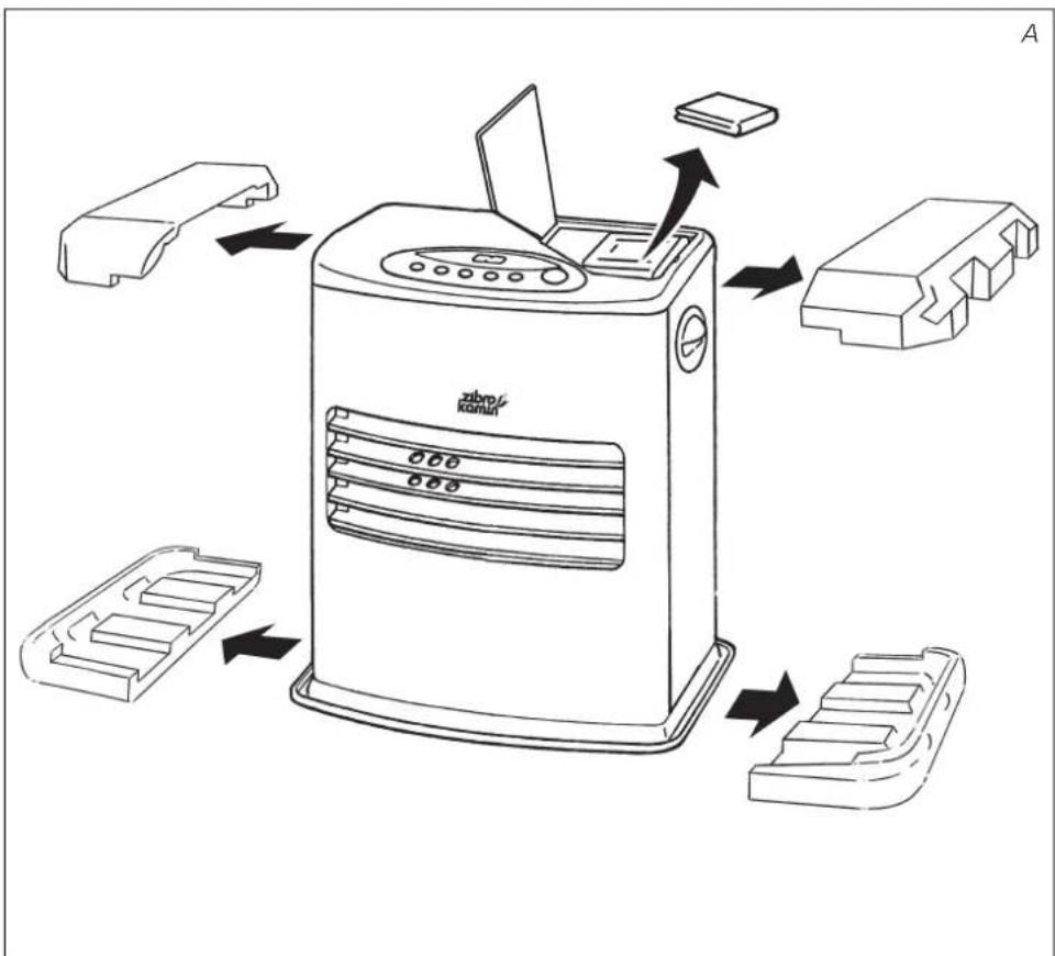
1 Remove all packaging materials (Fig. A).
2 Fill the removable tank ⑦ (refer to Section B, Fig. D).
3 Insert the plug into the wall-socket.
4 Ignite the heater using the key 13 (refer to Section D).
5 If required, change the temperature using the adjustment keys (refer to Section E).
6 Switch off the heater by pressing the key ⑬.
- The first time you ignite your heater it will smell like 'new' for a short time.
- Store your fuel in a cool and dark place.
- Fuel has a limited shelf life. Start every heating season with renewed fuel.
- The right quality of fuel will be assured, when you use Zibro Plus for your heater.
- If you change to another brand and/or type of parrafin oil, you must first finish up all the remaining fuel in the heater.
MAIN COMPONENTS
1 Front plate
② Grid
③ Base plate
4 Lid for removable tank
⑤ Operation panel
6 Handle
⑦ Removable tank
8 Air filter cap
9 Vent filter
10 Thermostat
⑪ Plug + cord
⑫ Information display
13 ⏻ key
14 Childproof lock
15 Adjustment keys (time and temperature)
16 TIMER
17 SAVE key
18 Indicator lights
19 Connection weektimer
Only the use of the correct fuel will ensure safe, efficient, and comfortable use of your Zibro Kamin.

This transportation cap is packed separately in the box. Only this cap ensures trouble-free transportation of the heater after use. Store it well!
WHAT YOU NEED TO KNOW IN ADVANCE
ALWAYS MAKE SURE THAT THERE IS SUFFICIENT VENTILATION
For each Zibro Kamin model the minimum size of space is specified in which you can use the heater safely, without additional ventilation (refer to Section P). If a particular room is smaller than the specified space, always leave a window or door slightly ajar ( ± 2.5 cm). We also recommend doing this in highly insulated or draught-free rooms and/or at altitudes above 1,500 metres. However, if there is insufficient ventilation (i.e. oxygen), the heater will automatically switch off. Do not use your Zibro Kamin in cellars or other underground areas.
THE RIGHT FUEL
Only use Class C1 paraffin fuel in accordance with BS2869: Part 2, or equivalent. Your Zibro Kamin heater has been designed for use with high-quality water-free pure paraffin oil, such as Zibro Plus. Only fuels of this kind will ensure clean and proper burning. Lower quality fuel may result in:
▶ increased possibility of malfunctioning
▶ incomplete burning
▶ reduced heater lifetime
▶ smoke and/or smells
▶ deposits on the grid or mantle
Using the right fuel is therefore essential for safe, efficient, and comfortable use of your heater.
Always refer to your local Zibro Kamin dealer for the right fuel for your heater.
text_image
Zibro
KOMINI
A INSTALLING THE HEATER
1 Carefully remove your Zibro Kamin from the box and check the contents. In addition to the heater you also need to have:
▶ a manual fuel pump
▶ a transportation cap
▶ these directions for use
Keep the box and the packaging materials (Fig. A) for storage and/or transportation.
2 Open the lid of the removable tank ④ and remove the piece of cardboard.
3 Fill the removable tank as indicated in Section B.
4 The floor should be firm and completely level. Reposition the heater, when it is not level. Do not try to correct the situation by placing books or other goods under the heater. Please refer to the separate instruction in the carton box for fixing of the heater.
5 Insert the plug ⑪ into the wall-socket (220/230 Volts - AC / 50 Hz) and set the correct time using the adjustment keys ⑮ (refer to Section C).
6 Your Zibro Kamin is now ready for use.
B FILLING FUEL
Do not fill the removable tank in the living room, but in a more suitable place (there can always be some spillage). Follow the procedure below:
1 Make sure that the heater is switched off.
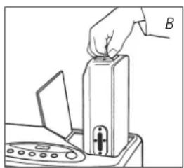
2 Open the lid ④ and lift the removable tank ⑦ out of the heater (Fig. B). Note: Some drops may leak from the tank. Put down the removable tank (cap pointing upwards) and screw off the fuel cap.
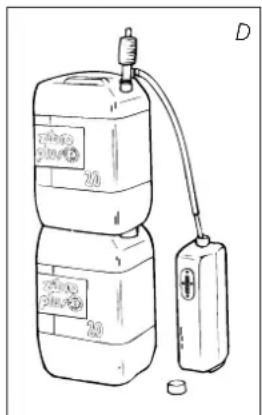
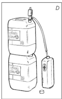
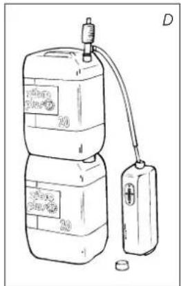
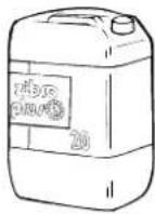
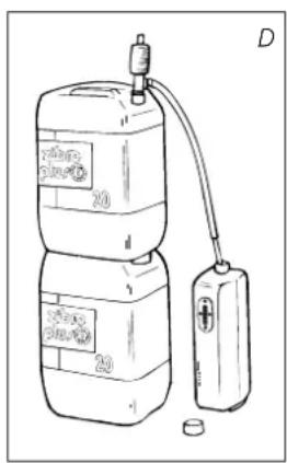
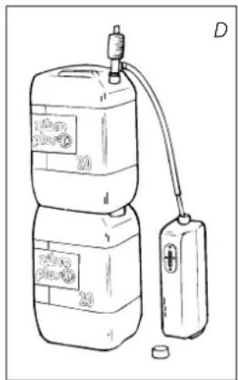
3 Take the manual fuel pump and insert the smooth, most rigid tube into the jerrycan. Make sure that it is in a higher position than the removable tank (Fig. D). Insert the ribbed hose into the opening of the removable tank.
4 Lock the switch button on top of the pump (turn clockwise).
5 Squeeze the pump a few times, until fuel starts flowing into the removable tank. As soon as this happens, there is no need to press any longer.
natural_image
Illustration of a hand inserting a component into a device (no text or symbols visible)
natural_image
Line drawing of a water pump connected to a digital device (no text or symbols)
natural_image
Two identical oval electronic connectors with pins, labeled 'empty full' below (no text on connectors)
text_image
temp.
clock
set
20
ave
timer
F: When the CLOCK indicator light stops blinking, the setting has been locked to the indicated value.

text_image
temp.
clock
set room
20:15
e timer vent.
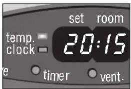
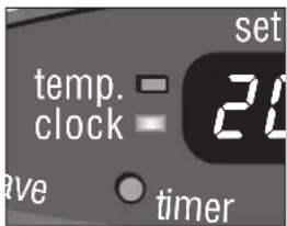
G: The required temperature on the left, the measured temperature on the right.
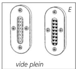
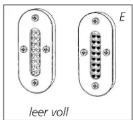
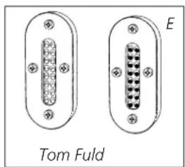
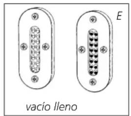
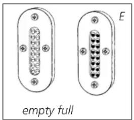
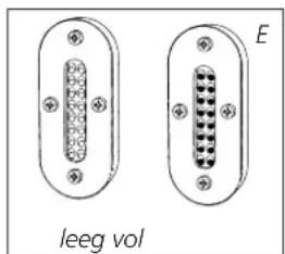
6 Check the removable tank fuel gauge ⑦ while filling the tank (Fig. E). Stop filling by loosening the switch button on top of the pump (turn anti-clockwise), once the gauge indicates that the tank is full. Never overfill the tank, especially not when the fuel is very cold (fuel expands when it heats up).
7 Let the remaining fuel in the pump flow back into the jerrycan and carefully remove the pump. Carefully screw the fuel cap back on the tank. Clean off any spilled fuel.
8 Check whether the fuel cap is straight and tightened properly. Reinstall the removable tank in the heater (cap down). Close the lid.
C SETTING THE CLOCK
It is only possible to set the correct time, when the heater is connected to the mains and not burning. Use the adjustment keys 15 to set the time. First press either of the two keys to switch on the function (the CLOCK light and the information display 12 will start blinking). Next, set the hours using the key on the left (▼hour) and the minutes using the key on the right (▲min.). Press once to increase the value by one step. When you hold down the key, the value will continue going up, until you release the key again. After approximately 10 seconds the blinking will stop and the setting will be locked. 5 minutes after switching off the heater, the information on the display will disappear and the heater will automatically switch into the stand-by position.

When the heater has been unplugged (or after a power failure), the time needs to be set again.
D IGNITING THE HEATER
When used for the first time, a new heater may give out a smell for a short while. You should therefore provide extra ventilation.
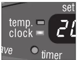
Always ignite the heater with the button 13. Never use matches or a cigarette lighter. Just press the button 13 to ignite the heater. The button will start blinking, indicating that the ignition procedure has started. This will take a short while. Once the heater is burning, the button 13 will remain lit (red). The information display 12 will show two numbers. The light next to them indicates that these numbers refer to the temperatures (Fig. G). The actual room temperature is indicated below ROOM, while the temperature setting is indicated below SET. The latter can be changed with the adjustment keys (refer to Section E). Prior to igniting the heater, always check for sufficient fuel in the removable tank.
E SETTING THE REQUIRED TEMPERATURE
The temperature setting can only be adjusted, when the heater is burning. Use the adjustment keys 15 to adjust the temperature. First press either of the two keys to switch on the function (the TEMP light next to the information display 12 will start blinking). Next, adjust the temperature using the key on the right (▲min.) to set the temperature to a higher setting and the key on the left (▼hour) to lower the temperature. Press once to increase the value one step. After approximately 10 seconds the light will stop blinking and the setting will be locked (Fig. G).
The available temperature settings range from 6^ C minimum to 28^ C maximum. When the heater has been unplugged (or after a power failure), the temperature will reset to the factory setting of 20^ C.
F USING THE TIMER
The timer allows you to switch on the heater automatically at a preset time. In order to switch on the timer, the correct time must have been set (refer to Section C) and the heater should be off. Follow the procedure below:
1 Press the button ⑬ and then the TIMER key ⑯ immediately after that. The TIMER light and the information display ⑰ will start blinking.
2 Use the adjustment keys 15 to set the time at which the heater must ignite. Use the key on the left (▼hour) to set the hours and the key on the right (▲min.) to set the minutes (interval of 5 minutes).
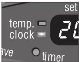
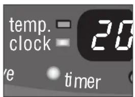
3 After approximately 10 seconds the information display will show CLOCK again and the TIMER indicator light will light up, indicating that the timer function has been activated (Fig. H).
4 The timer will ensure that the room will have been heated to approximately the required temperature at the set time.
text_image
temp.
clock
20
e timer
H: The TIMER indicator light indicates that the timer function has been switched on.

When you want to switch off the heater and ignite it again with the timer, all you have to do is press the TIMER key (refer to Section G).
Press the button 13 once to clear the timer setting.

If you would like more extensive timer possibilities, we advise you to procure the Zibro Kamin weektimer. This timer is easy to connect with your Zibro Kamin Heater, see 19.
G SWITCHING OFF THE HEATER
There are two ways to switch off the heater.
1 Press the ⏻ button ⑬. The information display will show the CLOCK signal. Within approximately one minute the flame will have extinguished.
2 Press the TIMER key 16, when you want to switch off the heater and ignite it again with the timer the next time. This not only switches off the heater, but it also activates the timer function. You can change the required time with the adjustment keys 15 (refer to Section F).
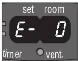
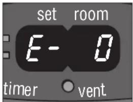
The information display ⑫ not only serves as an indicator of the (set) time and temperature (Sections C, E, and F), it also indicates any malfunctioning of the heater. The code on the information display tells you what is the matter:
text_image
set room
E-0
timer vent
In case of any malfunctioning the information display will tell you what is the matter.
text_image
set room
65 Hr
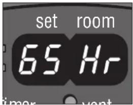
text_image
set room
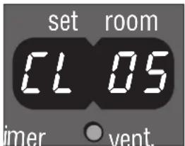
CL 05
imer vent.
natural_image
Close-up of a car's key and ball on a road (no text or symbols visible)
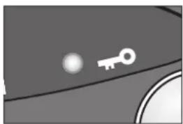
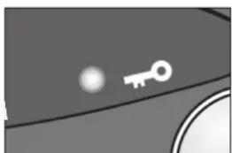
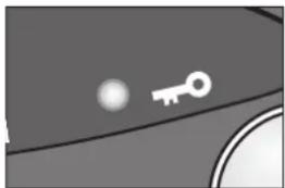
I: When the KEY-LOCK light lights up, the childproof lock has been activated.
GB
E - O Temperature within the heater too high. Cool-down and re-ignite.
F - ☐ Power interrupted. Re-ignite the heater.
E - / Faulty thermostat. Contact your dealer.
F - / Faulty burner thermistor. Contact your dealer.
E - 2 Starting problems. Contact your dealer.
E - 5 Tipping-over protection. Re-ignite the heater.
E - Poor burning. Contact your dealer.
E - 7 Room temperature If necessary,
above 28°C. re-ignite the heater.
E - B Defective booster. Contact your dealer.
E - 9 Air filter dirty; or Clean filter
Fuel pump dirty.
Contact your dealer.
65 Hr The heater has been in operation continuously for a period of 65 hours and has turned itself off automatically.
Switch the heater back on.
-- : -- Out of fuel.
Refill removable tank.
(& blinking
FUEL-light)
Always contact your Zibro Kamin dealer for any malfunctioning not listed above.
AUTOMATIC DEACTIVATION
This heater is fitted with a safety system that ensures that it switches off automatically after 65 hours continuous operation. The following will then appear in the display: 5 if desired, you can switch the heater on again by pressing the ⏻ button 13 (see section D).
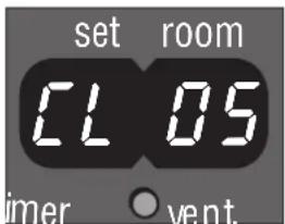
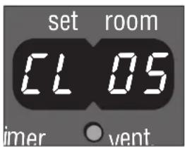
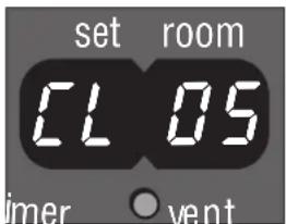
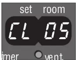
AUTOMATIC CLEANING MODE
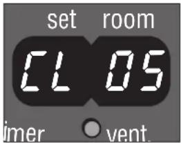
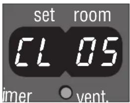
When the heater has been burning continuously for two hours at its highest setting, the burner will automatically start an autoclean procedure. The display will show the autocleaning code CL-05 running back to CL-08. The procedure takes 5 minutes, during which the heater will burn at its lowest setting, while the burner autocleans. When the burner is clean again, the heater will automatically switch back to the highest setting again.
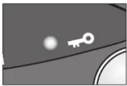
CHILDPROOF LOCK
The childproof lock can be used to prevent children accidentally changing the heater settings. When the heater is burning and the childproof lock is on, the heater can only be switched off. Other functions are blocked then. If the heater has already been switched off, the childproof lock also prevents accidental ignition of the heater. Activate the childproof lock by pressing the appropriate key
14 and holding it down for more than 3 seconds. The KEY-LOCK indicator light will light up (Fig. I), indicating that the childproof lock has been activated. Switch off the childproof lock by pressing the key 14 and holding it down for more than 3 seconds once again.
J THE CORRECT USE OF 'SAVE'
The 'SAVE' function allows you to limit the temperature. When this function is activated, the heater will automatically switch off, when the room temperature

text_image
ten
clo
save
J: When the SAVE light lights up, the heater will automatically switch on or off in order to remain within a specified temperature range.
text_image
10
vent fuel
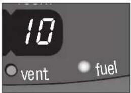
K: When the FUEL indicator light is lit, the information display will show the number of minutes of fuel left in the tank.

text_image
Timer
vent.
L: A blinking VENT indicator light is a sign that you need extra ventilation.
natural_image
Illustration of a hand inserting a grid into a device labeled M (no text or symbols on the device itself)

text_image
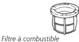
Fuel filter
N
exceeds the set temperature by 3°C. Subsequently, when the room temperature has dropped again to the set temperature, the heater will automatically switch on again. Activate the 'SAVE' setting by pressing the appropriate ⑰ key. The SAVE indicator light will light up (Fig. J). Switch off the function by pressing the SAVE key once again.

Without the 'SAVE' setting your heater will maintain the set temperature by approximation as well, by adjusting its heating capacity. 'SAVE' is an economy setting, which you can use when, for instance, you are not present in the room or to keep it frost-free.
K THE 'FUEL' INDICATOR LIGHT
When the FUEL indicator light lights up, there is enough fuel left for another 10 minutes of heater use. The count-down of the remaining heating time can be seen in the information display ⑫ (Fig. K). Every two minutes an alarm signal is sounded, warning you to refill the removable tank. If you do not react, the heater will extinguish by itself. The heater will also sound a warning signal, when it switches off. The FUEL indicator light will blink, while four lines are blinking in the information display. You can stop this by pressing the button ⑬ once.
Once the heater has used up all its fuel and extinguished, it will take some time, after the refill, before the heater is completely ready for use again.
L THE 'VENT' INDICATOR LIGHT
When the VENT indicator light starts blinking, this is a sign that the room is not vented sufficiently (Fig. L). The heater will switch off automatically. If the indicator light continues blinking after extra ventilation, please contact your Zibro Kamin dealer.
M MAINTENANCE
Switch off the heater and let it cool down, before you start any maintenance work. Also disconnect the plug from the mains.
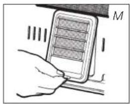
Your Zibro Kamin needs hardly any maintenance. It is, however, important that you clean the air filter cap ⑧ and the vent filter ⑨ with a vacuum cleaner and the grid ② with a damp cloth, both on a weekly basis. Remove the air filter cap occasionally (Fig. M) and clean it with soapy water. Prior to reinstallation, make sure that the air filter cap has fully dried.
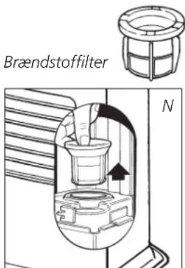
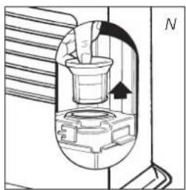
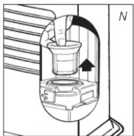
Regularly inspect the fuel filter as well:
1 Remove the removable tank ⑦ from the heater and remove the fuel filter (Fig. N). Some drops may leak from the filter; keep a cloth at hand.
2 Remove the dirt by tapping the fuel filter upside-down against a hard surface. (Never clean it with water!)
3 Reinstall the fuel filter into the heater.
We recommend that you remove dust and stains in time with a damp cloth, because otherwise these may cause stains that are hard to remove.

Do not remove any heater components yourself. Always contact your Zibro Kamin dealer for repairs. When the power cord is damaged, it may only be replaced by an authorised fitter. Use a new cord of the type H05 VV-F.
N STORAGE (END OF THE HEATING SEASON)
At the end of the heating season, you must store the heater in a dust-free place, if possible in its original packaging. Unused fuel cannot be used in the next heating season. We therefore recommend that you burn up all fuel. If there is still some fuel left, do not throw it away, but dispose of it in accordance with the local regulations for the disposal of domestic chemical waste.
Always start the new heating season with fresh fuel. When you start re-using the heater follow the instructions again (starting from section A and as specified).
O TRANSPORTATION
Take the following measures to avoid fuel leakage during the transportation of the heater:
1 Let the heater cool down.
2 Remove the removable tank ⑦ from the heater and remove the fuel filter (refer to Section M, Fig. N). Some drops may leak from the filter; keep a cloth at hand. Store the fuel filter and the removable tank outside the heater.
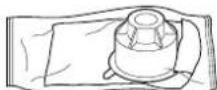
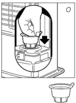
3 Place the transportation cap into the position of the fuel filter (Fig. O). Press it tight.
4 Always move the heater in an upright position.
natural_image
Diagram of a hand pressing down inside a container with a downward arrow, alongside a small inset image of a mortar (no text or symbols)
transportation cap
P SPECIFICATIONS
| Ignition electrical Dimensions (mm) width 405 |
| Fuel paraffin (including base plate) depth 295 |
| Capacity (kW) max. 3.0 height 435 |
| Capacity (kW) min. | 0.8 Accessories | manual fuel pump |
| Suitable space ( m^3 )** | 30-120 | transportation cap |
| Fuel consumption (l/hr)* | 0,313 Mains | 220V/230V |
| Fuel consumption (g/hr)* | 250 | -- AC/50 Hz |
| Burning time per tank (hr)* | 17.3 Electrical consumption | igniter 320 W |
| Capacity removable tank (litres) | 5,4 | continuous 32 W |
| Weight (kg) | 10 Fuse rating | 250V, 5A |
* At maximum setting ** Specified values are indicative
Q WARRANTY PROVISIONS
Your heater comes with a 24-month warranty starting on the date of purchase. Within this period all defects in material or workmanship will be repaired without any charge. The following provisions shall apply regarding this warranty:
1 We expressly dismiss all other claims for damages, including consequential damages.
2 Any repairs or replacements of components within the term of warranty will not result in an extension of the term of warranty.
3 The warranty shall no longer apply, when the heater has been modified, non-original parts have been used, or when it is repaired by third parties.
4 The warranty shall not apply to parts that are subject to normal wear, such as the burner mat and the manual fuel pump.
5 The warranty shall only apply, when you present the original, dated proof of purchase, provided no changes have been made to it.
6 The warranty shall not apply to damages caused by actions not in compliance with the Directions for Use, neglect, and the use of an incorrect type of fuel, or fuel past its use-by date. The use of incorrect fuel can even be dangerous*.
7 Transportation costs and the risks involved during the transportation of the heater or heater components shall always be for the account of the purchaser.
In order to avoid unnecessary costs, we recommend that you always read the 'Directions for Use' carefully first. In case they offer no solution, please take the heater to your dealer for repair.
* Highly inflammable substances may induce uncontrollable burning, causing flames to break out. Should this happen, never try to move the heater, but always switch off the heater immediately. In case of emergency you may use a fire extinguisher, but only a type B extinguisher: a carbon dioxide or powder extinguisher.
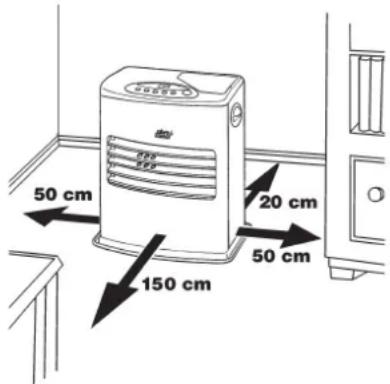
10 TIPS FOR SAFE USE
text_image
50 cm
150 cm
20 cm
50 cm
1 Make sure that children are always aware of the presence of a burning heater.
2 Do not move the heater when it is burning or still hot. Do not refill nor service the heater when it is burning or still hot.
3 Position the front of the heater at a distance of minimum 1.5 metres from walls, curtains, and furniture.
4 Do not use the heater in dusty rooms. You will not have optimum burning in such rooms. Do not use the heater in the immediate surrounding of a bath, a shower or a swimmingpool.
5 Switch off the heater, before you leave or go sleeping. Unplug the heater as well, when you go away for a longer period of time (e.g. holidays).
6 Store and move fuel only in suitable tanks and jerrycans.
7 Make sure that the fuel is not exposed to heat or extreme temperature changes. Always store the fuel in a cool, dry and dark place (sunlight will affect the quality).
8 Never use the heater in places where harmful gasses or fumes may be present (e.g. exhaust gasses or paint fumes).
9 Beware that the grid of the heater becomes hot. If the appliance is covered there is a risk of fire.
10 Always make sure that there is sufficient ventilation.
Egregio Signore, Gentile Signora,
natural_image
Illustration of a hand inserting a component into a device (no text or symbols visible)

natural_image
Line drawing of a water pump connected to a battery, showing internal components and wiring (no text or symbols)
text_image
temp.
clock
set
20
ave
timer
text_image
temp.
clock
set room
20:15
re timer vent.
D ACCENSIONE DELLA STUFA
text_image
set room
E-0
timer vent.
text_image
set room
65 Hr
timer vent
text_image
set room
CL 05
imer vent

natural_image
Close-up of a key icon on a curved surface with a small sphere (no text or symbols)
text_image
tem
clo
save
text_image
10
vent. fuel
natural_image
Hand inserting a grid into a device (no text or symbols visible)
Filtro del combustibile
natural_image
Cross-sectional diagram of a mechanical device with internal components and an arrow indicating direction (no text or symbols)
natural_image
Diagram of a hand pressing down on a cup inside a container, with a small inset showing the same cup (no text or symbols present)
WAT U VOORAF MOET WETEN
ALTIJD VOLDOENDE VENTILEREN
natural_image
Illustration of a hand pressing a button into a device (no text or symbols visible)
natural_image
Line drawing of a water pump connected to a digital device (no text or symbols)
text_image
leeg vol
E
text_image
temp.
clock
set
20
ave
timer
text_image
temp.
clock
set room
20:15
re timer vent.
text_image
temp.
clock
20
ve timer
text_image
set room
E-0
timer vent.
text_image
set room
65 Hr
text_image
set room
CL 05
timer vent.
natural_image
Close-up of a key icon on a curved surface with a small sphere (no text or symbols)
text_image
tem
clo
save
text_image
10
vent. fuel
text_image
timer
vent.
natural_image
Illustration of a hand inserting a grid into a device labeled 'M' (no text or symbols on the device itself)

natural_image
Cross-sectional diagram of a mechanical device with internal components and an arrow indicating direction (no text or symbols)


natural_image
Diagram of a hand inserting a component into a housing, showing a downward arrow (no text or symbols)

Transportdop
N OPSLAG (EINDE STOOKSEIZOEN)
Holloway Bank, Wednesbury
West Midlands WS10 0AW
Tel.: +44 121 506 1818
Fax: +44 121 505 1744
email: gases@lister.co.uk
ITALIA
PVG Italy SRL
Via Niccolò Copernico 5
50051 CASTELFIORENTINO (FI)
tel: +39 571 628500
fax: +39 571 628504
email: pvgitaly@zibro.com
N NORGE
Sunwind - Gylling A/S
Rudsletta 71-75 / P.O. Box 64
N-1309 RUD
tel: +47 67 17 13 70
fax: +47 67 17 13 80
email: pvgint@zibro.com
NL NEDERLAND
PVG International b.v.
P.O.Box 96
5340 AB OSS
tel: +31 412 694694
fax: +31 412 622893
email: pvgnl@zibro.com
PORTUGAL
Gardena, Lda

