PAX120 Plus - Receiver ALECTO - Free user manual and instructions
Find the device manual for free PAX120 Plus ALECTO in PDF.

User questions about PAX120 Plus ALECTO
0 question about this device. Answer the ones you know or ask your own.
Ask a new question about this device
Download the instructions for your Receiver in PDF format for free! Find your manual PAX120 Plus - ALECTO and take your electronic device back in hand. On this page are published all the documents necessary for the use of your device. PAX120 Plus by ALECTO.
USER MANUAL PAX120 Plus ALECTO
natural_image
Interior view of an electronic circuit board with visible wiring and components (no readable text or symbols)MUTE:
WAARSCHUWING/ONDERHOUD
Raccordement XLR contact 1 = blindé (GND)
contact 2 = signal +
contact 3 = signal -
Raccordement Jack contact 1 = blindé (GND)
contact 2 = signal -
contact 3 = signal +
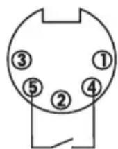
Raccordement DIN contact 1 = signal +
contact 2 = blindé (GND)
contact 3 = signal -
contact 4 = CHIME
contact 5 = GND


text_image
1 2 3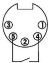
natural_image
Interior view of an electronic circuit board with visible wiring and connectors (no readable text or symbols)MUTE:
- Mic 1 input (phone)
- Mic 1 volume control
- Mic 2 volume control
- Mic 3 volume control
- Aux 1 volume control
-
Aux 2 volume control
-
Master tone control (bass)
- Master tone control (treble)
- Master-volume control
- Power ON/OFF switch
- Output level indicator

text_image
12 13 14 15 Alecto® 115V~ 220V~ Approximate voltage Connected for 2.0kV~ LINE FUSE CE DO 34V = COM 8C 25V 70V 108V PRE OUT POWER 16 TAPE OUT AUX 2 AUX 1 TEL/POWER LNG □ MRC MRC 3 MRC 2 MRC 1 ON □ OFF 24 25 26 27 28 29 16 17 18 19 20 21 22 23- Mains voltage selector switch
- Mains input socket
- AC fuse holder PAX-30 (T1A/250V)
PAX-120 (T 2.5A/250V) - DC power & output terminals
- Mic 3 Line/Mic selector switch
- Mic.3 XLR-input (balanced)
- Mic.3 Jack-input (phone/balanced)
- Mic.2 XLR-input (balanced)
-
Mic.2 Jack-input (phone/balanced)
-
Mic 1 XLR-input (balanced)
- Mic 1 DIN-input (balanced) CHIME / MUTE connector
- CHIME ON/OFF switch
- Pre-out / Power-IN (RCA phono)
- Tape output (RCA phono)
- AUX 2 input (2x RCA phono)
- AUX 1 input (2x RCA phono)
- TEL/EMER input terminals
- TEL/EMER input level control
INSTALLATION
ATTENTION
Make sure the ventilation openings at the top and bottom of the amplifier remain clear to guarantee a continuous convection.
During installation, set the POWER switch of the amplifier to OFF (0) and set the MIC-1, 2 & 3 controls and the AUX-1 & 2 controls to minimum (0); do not connect the power supply yet.
INPUT
MICROPHONE:
MIC1 input is either a standard 1/4" mono jack on front panel or XLR and DIN on the rear panel (with selectable phantom power).
XLR (balanced operation)
Pin 1 = ground (GND)
Pin 2 = signal live
Pin 3 = signal return

1/4" stereo Jack (balanced operation (backside only)*
Pin 1 = ground (GND)
Pin 2 = signal live
Pin 3 = signal return

natural_image
Diagram of a mechanical component with three labeled parts (1, 2, 3), no text or symbols present.DIN (balanced operation)
Pin 1 = Signal live
Pin 2 = ground (GND)
Pin 3 = Signaal -
Pin 4 = CHIME
Pin 5 = GND
*: the frontside 1/4" jack is a standard mono version
MIC1 input has VOX priority which will override MIC2 / MIC3 and AUX1 / AUX2 input signals but NOT the TEL/EMER input.
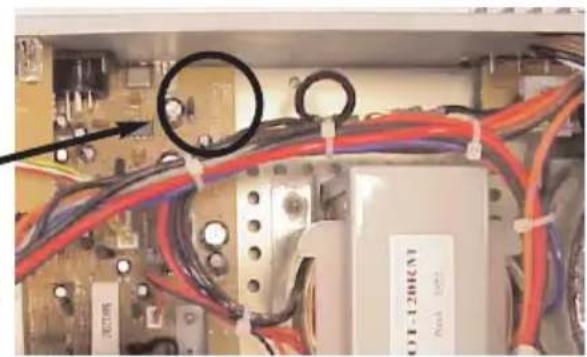
MIC1-3 input are XLR, DIN and phone jack with selectable phantom power located on the rear panel and wired as above. The phantom power is factory set to off and can be enabled as follow:
- Remove power lead trom the AC wall socket.
- Remove top cover.
- Locate the jumper
- connect jumper to the centre pin and ON position to enable the phantom power
ALWAYS DISCONNECT THE AMPLIFIER FROM THE MAINS WHEN REMOVING THE COVER.
natural_image
Interior view of an electronic circuit board with visible wiring and components (no readable text or symbols)CHIME:
Switching on the manual chime on/off switch on the rear panel and short the pin4, pin5 of the DIN Socket will activate the chime function ("Ding-Dong" attention signal preceding a call).
AUX:
The equipment provides two auxiliary inputs which may be used for connecting other signal sources such as a Radio Tuner, CD or Cassette player. The level Control operates on each of the input sources. Turn the control clockwise to increase the volume or anticlockwise to reduce the volume.
The Aux input sockets are standard RCA phono, two sockets are supplied and these are linked together internally, this allows stereo signal sources to be used without the need to obtain a special lead, however you may wish to check with the manufacturer of the signal source to ensure that no damage will result if the left and right output channels are put in parallel.
In case the backside switch LINE/MIC is set to 'LINE' this input can be used for music as well.
TEL/EMER:
This input is for emergency announcements/signals and is not effected by the master volume control. Input level can be set by level control on the rear. The TEL input has the highest priority and will override all other inputs.
Be aware that the telephone exchange must have a 'babyphone' or 'room listening' functionality.
POWER IN AND PRE OUT:
Connects the mixer/preamplifier stage to the power amplifier stage. The connecting link must be plugged in for normal operation as a mixer/amplifier. If a compressor/limiter, equalizer, or other external signal processor is used in the sound system, connect the "PRE OUT to the input of the external processor and the output of the processor to" POWER IN" In the signal chain, "PRE OUT" is after the tone controls and the master volume control.
LOW IMPEDANCE:
Use the COM-8 Ohm output in case the distance to the loudspeakers is shorter than 50 to 75 metres.
When using low impedance loudspeakers, the total power of the loudspeakers should be equal or larger than the amplifier output. Otherwise one or more
loudspeakers will be damaged when the output is at its maximum. Make sure the total impedance remains in between 4 and 16 ohm:
When connected in series, the impedances of each of the speakers can be added.
When (equal) loudspeakers are connected in parallel, the impedance of a single loudspeaker must be devided by the number of speakers.
Eventually, use a combination of series and parallel connection to obtain the required impedance.
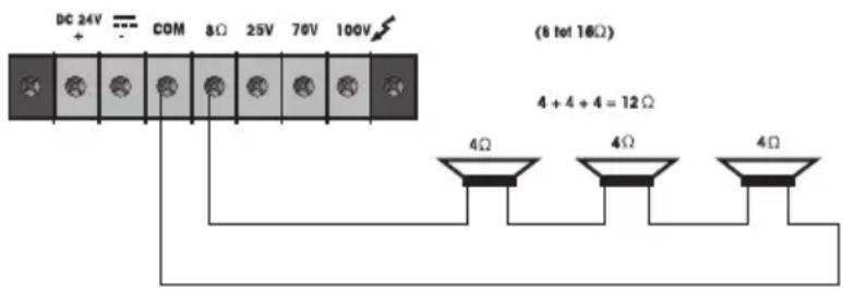
text_image
DC 24V COM 8Ω 25V 70V 100V (8 to 16Ω) 4 + 4 + 4 = 12Ω 4Ω 4Ω 4Ω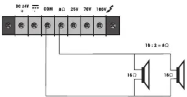
text_image
DC 24V + COM 8Ω 25V 70V 100V 16:2 = 8Ω 16Ω 16ΩLINE OUTPUT:
Use the COM-25V, COM-70V or COM-100 V output terminals for loudspeaker-distances of more than 50 to 75 metres. Use only speakers with a line transformer.
In case of connection to the 100 volt output, the power of all loudspeaker (-transformers) connected should be equal or less than the effective RMS output power of the amplifier (PAX-30 = 30 Watt / PAX-120 = 120Watt).
Should more loudspeakers be connected than the amplifier can supply, the amplifier will burn out no matter what the settings of the volume controls are.
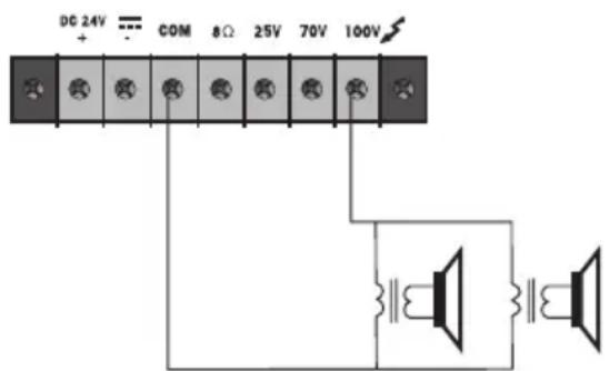
text_image
DC 24V + COM 8Ω 25V 70V 100VAll loudspeakers should be connected in parallel; with the 100 volts system, series connection is not allowed.
In case the total loudspeakerpower exceeds the amplifier's power, use the 70 volt output; it is now allowed to connect loudspeakers up to twice the amplifier power.
When the 25V output is used, it is allowed to connect loudspeakers up to 4 times the amplifier power
As a rule of thumb, loudspeaker transformers are provided with several power terminals obtaining a larger flexibility; use the low power terminal where less volume is required and use the high power terminal where more volume is required.
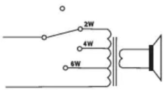
text_image
2W 4W 6WIt is allowed to provide individual loudspeakers with an on/off switch or with a rotary switch (with connections to several terminals) to obtain a kind of volume control.
WHEN USING THE 25, 70 OR 100 VOLTS LOUDSPEAKER SYSTEM, THE SAME RULES SHOULD BE APPIED AS ARE VALID FOR THE 230 VOLTS MAINS SUPPLY. COUNCEL YOUR ENERGY COMPANY.
TAPE OUT:
These standard RCA phono sockets provide a mixed output suitable for connection to a tape or Cassette recorder.
POWER SUPPLY:
Connect the amplifier either to the mains 230 VAC (power cord included) or to a 24V / 10A DC power source.
WARNINGS:
When using a battery supply, the cabinet of the amplifier will be connected to the “-” (minus) of the supply. When using a 230 Vac mains supply, the cabinet of the amplifier will be connected to the ground of the mains. Connect the amplifier to a grounded outlet only.
USAGE
ATTENTION:
Prior to switch-on the amplifier, set the MIC-1, 2 & 3 controls and the AUX-1 & 2 controls to minimum (0).
MUSIC:
With the AUX-1/2 controls you control the volume of the music sources connected to the AUX-1/2 inputs. Input MIC-3 can be switched into a music input (position 'LINE'). Use control MIC-3 to control the volume,
Microphone:
The MIC-1, MIC-2 and MIC-3 controls control the volume of the microphones connected to the equal named inputs (see rear of amplifier).
MASTERVOLUME:
Use the MASTER control to adjust the master volume except the volume from the TEL/EMER input.
TONE CONTROL:
Use the BASS control to amplify (clockwise) or weaken (anti-clockwise) the low frequency signals. Use the TREBLE control to amplify (clockwise) or weaken (anti-clockwise) the high frequency signals.
TEL/EMER VOLUME:
Use the control (29) on the rear to control the volume of the telephone / emergency signal. The MASTER control does not affect this volume.
AUTO MUTE:
As soon and as long there is speech present in the microphone connected to the MIC-1 input, all other signals, excluding the TEL/EMER input, are being suppressed.
CHIME:
When connecting a pushbutton between PIN-4 and PIN-5 of the rear-side DIN socket, you can generate a DING DONG signal. This pushbutton can be built-in into a (table)microphone.
- never use the amplifier in moist or wet surroundings;
- the amplifier may only be opened and repaired by authorised personnel; the amplifier does not contain spare parts;
- do not (let) drop any objects through the ventilation holes; if this happens, immediately switch off the amplifier and cut the power supply. Bring your amplifier to your dealer;
- make sure the ventilation openings at the top and bottom of the amplifier have a clearance of at least 1 to 2 cm to guarantee a continuous convection;
- the cabinet of the amplifier is connected with ground of the mains and with the “-” (minus) of the DC supply;
- clean the cabinet with a light moist cloth only; switch off the amplifier before you start cleaning;
- switch on the amplifier only after setting all controls to MINIMUM (0), this prevents plops;
- when exposed to a high volume for a long period of time, the hearing might be damaged;
- set the volume in such a way that other sounds from the surroundings still reach you and others.
SPECIFICATIONS
Supply: AC115V / 230V, 50 / 60Hz±10% switchable
Battery Voltage: DC 24V (MAX 10 % deviation)
Outputs: Speaker outputs: 8 Ohm, 25V, 70V, 100V
PAX-30: Rated 30W max. 45W
PAX-120: Rated 120W max. 180W
Tape out: 350mV, 4,7KOhm
Inputs: Mic1\~Mic3: 1mV, 250Ohm balanced with phantom
power selectabel.
Aux1: 200mV, 47KOhm, unbalanced.
Aux2: 500mV, 47KOhm, unbalanced.
Line (Mic3): 200mV, 47KOhm, balanced.
TEL: 0.1\~1V, 600Ohm, adjustable, balanced.
Power in: 1V, 47KOhm, unbalanced
Frequency response: Mic1\~Mic3: 60Hz \~15KHz ±3dB
Aux1\~Aux2: 60Hz\~15KHz ±3dB
TEL : 100Hz \~ 15KHz ±3dB
Total harmonic distortion: Less than 1% at 1KHz, rated power
Signal to noise ratio: All volume controls C.C.W.:75dB below rated power
Mic1 \~ Mic3: 60dB below rated power
Aux1 \~ Aux2: 70dB below rated power
TEL: 70dB below rated power
Tone controls: Bass: ± 10dB at 100Hz
Treble ± 10dB at 10KHz
Controls: Mic1 \~ Mlc3 volume control
Aux1 \~ Aux2 volume control
Master volume control
Tone controls (Bass, Treble)
TEL input level control
Mic3(Line-Mic) selector switch
Chime on/off switch
AC 115V/230V voltage selector switch
Indicators: Power indicator (LED), output level indicators (3 LED)
AC power consumption: PAX-30 = 90 Watts PAX-120 = 360 watts
DC power consumption: PAX-30 = 2 A PAX-120 = 8A
Priority (VOX): Priority level (Using for mic1, the 5 pole DIN
connector, phone jack or XLR connector). TEL/EMER
(3), Mic1 (2), Mic2 (1), Mic3 (1), and Aux/CD (1).
Dimentions ( H x W x D ): 88 x 430 x 260 mm
Weight: PAX-30 = Approx 6.5Kg PAX-120 = Approx 9.5Kg
Color: Black
GARANTIEBEWIJS
Naam: Bewaar hier
Adres: uw kassa- of koopbon
postcode:
Plaats:
Telefoon:
serienummer:
Address: your purchase
Zip-code: ticket
City:
Telephone:
You have a guarantee of 12 MONTHS after the date of purchase of this PAX-30/120plus. We guarantee during this period the free repair of defects caused by material- and construction faults. This at the importers discretion.
HOW TO ACT:
If you notice a defect, consult the manual first. If this manual gives you no definite answer, consult your dealer with a clear description of your complaint. He will collect the device together with this guarantee card and the dated purchase ticket and he will take care of a prompt repair, respectively free sending to the importer.
THE GUARANTEE EXPIRES:
When used inexpert, faulty connections, use of unoriginal parts or accessories, negligence and defects caused by fire, flood, stroke of lightning and natural disasters. With unqualified modifications or repairs by third persons. With incorrect transport without a suitable packing. If the device is not handed in with the correct filled in guarantee card and the purchase ticket.
All further responsibilities, in particular subsequent damages, are excluded.