SCANSTATION 730EX - Document Scanners KODAK - Free user manual and instructions
Find the device manual for free SCANSTATION 730EX KODAK in PDF.
| Product type | Professional document scanner |
| Brand | Kodak |
| Model | SCANSTATION 730EX |
| Scan format | Up to A4 (210 x 297 mm) |
| Automatic document feeder | Capacity up to 100 sheets |
| Scan speed | Up to 30 pages per minute (black and white) |
| Optical resolution | 600 x 600 dpi |
| Duplex scanning | Yes, automatic |
| Interface | USB 2.0 |
| Dimensions (W x D x H) | 320 x 260 x 180 mm |
| Weight | 4.2 kg |
| Power supply | 230 V, 50/60 Hz |
| Power consumption | 30 W (operating), 5 W (standby) |
| Output formats | PDF, TIFF, JPEG, BMP |
| Included software | Kodak Capture Pro, TWAIN driver |
| Maintenance and cleaning | Clean the rollers and glass with a lint-free cloth and scanner cleaner |
| Safety | Emergency stop, paper jam detection |
| Spare parts and repairability | Replacement rollers, maintenance kit available |
| General information | 1-year warranty, online technical support |
Frequently Asked Questions - SCANSTATION 730EX KODAK
User questions about SCANSTATION 730EX KODAK
0 question about this device. Answer the ones you know or ask your own.
Ask a new question about this device
Download the instructions for your Document Scanners in PDF format for free! Find your manual SCANSTATION 730EX - KODAK and take your electronic device back in hand. On this page are published all the documents necessary for the use of your device. SCANSTATION 730EX by KODAK.
USER MANUAL SCANSTATION 730EX KODAK
Scan Station 700 Series
KODAK Scan Station 700
KODAK Scan Station 710
KODAK Scan Station 720EX
KODAK Scan Station 730EX
Administrator's Guide
3rd Party Licenses
This software is based in part on the work of the Independent JPEG Group
Copyright (C)2009-2013 D. R. Commander. All Rights Reserved.
Redistribution and use in source and binary forms, with or without modification, are permitted provided that the following conditions are met:
- Redistributions of source code must retain the above copyright notice, this list of conditions and the following disclaimer.
- Redistributions in binary form must reproduce the above copyright notice, this list of conditions and the following disclaimer in the documentation and/or other materials provided with the distribution.
- Neither the name of the libjpeg-turbo Project nor the names of its contributors may be used to endorse or promote products derived from this software without specific prior written permission.
THIS SOFTWARE IS PROVIDED BY THE COPYRIGHT HOLDERS AND COLNTRIBUTORS "AS IS", AND ANY EXPRESS OR IMPLIED WARRANTY, INCLUDING, BUT NOT LIMITED TO, THE IMPLIED WARRANTY OF MERCHANTABILITY AND FITNESS FOR A PARTICULAR PURPOSE ARE DISCLAIMED. IN NO EVENT SHALL THE COPYRIGHT HOLDERS OR COLNTRIBUTORS BE LIABLE FOR ANY DIRECT, INDIRECT, INCIDENTAL, SPECIAL, EXEMPLARY, OR CONSEQUENTIAL DAMAGES (INCLUDING, BUT NOT LIMITED TO, PROCUREMENT OF SUBSTITUTE GOODS OR SERVICES; LOSS OF USE, DATA, OR PROFITS; OR BUSINESS INTERRUsION) HOWEVER CAUSED AND ON ANY THEORY OF LIABILITY, WHETHER IN CONTRACT, STRICT LIABILITY, OR TORT (INCLUDING NEGLIGENCE OR OTHERWISE) ARISING IN ANY WAY OUT OF THE USE OF THIS SOFTWARE, EVEN IF ADVISED OF THE POSSIBILITY OF SUCH DAMAGE.
Contents
Safety
Chapter 1 Overview 1
What's in the box 1
Setting up the Scan Station 2
Setting up configurations 3
Scan Station components 5
Front view 5
Inside view 6
Rear view 7
Chapter 2 Pre-installation Checklist 9
Network configuration details 9
Best practices 9
Pre-installation checklist 10
Chapter 3 Installation and Getting Started 15
Setup overview 15
Power saver mode and activating the Scan Station 15
Setup Wizard 16
Installing the
Kodak Scan Station 700 Series - Scanner Administration application 21
The main screen 22
24
File menu 24
Edit menu 25
Scanner menu 25
Help menu 28
Icons 28
Chapter 4 Configure Device Settings 31
Device Settings 31
Configuring your device options 33
Configuring email settings 38
Configuring Active Directory Server settings 41
Configuring Fax settings 43
Chapter 5 Define Scan Settings 49
To define scan settings 49
Scan Settings 51
Black and White Settings 52
Color Settings 53
Advanced Settings 56
PDF Settings 61
Filename Settings 62
Chapter 6 Index Templates 65
Creating an index template 66
Setup Index Templates screen 68
Index Template Settings screen 69
Index Template Settings (name) screen 72
Index Field Editor screen 73
Barcode Field Properties screen 74
OCR Field Properties screen 77
Use cases 78
Chapter 7 Create Destinations 81
Accessing the Destinations screen 81
Destination layout and terminology 82
Setting up a email destination 83
Importing an email address book 85
Setting up a network destination 87
Setting up a printer destination 89
Setting up a print server printer destination 89
Setting up a shared workgroup printer destination 91
Setting up a printer connected directly to the network 93
Setting up a FTP site 95
Setting up a fax or email to fax destination 98
Adding a SharePoint group 99
Adding a Kofax Front Office Server group 101
Chapter 8 Add and Manage Groups 103
Assigning groups 103
Adding Active Directory groups 105
Adding individual users 107
Finishing your group configuration 108
Chapter 9 Create Jobs 109
Chapter 10 Monitor and Manage Your Scan Stations 115
Scanners tab 115
The toolbar 115
Grid view 117
Network configuration options 118
Adding a Scan Station 118
Discovering devices 120
Modifying a Scan Station 121
Deleting a Scan Station 122
Changing a remote access password 122
Configurations/Configuration files 123
Updating your Scan Station 123
Method 1 124
Method 2 126
Method 3 128
Method 4 129
Method 5 130
Scan Station Security 131
Password protecting the Scan Station 132
Retrieving and clearing files 133
Retrieving the Scan Station log file 133
Clearing a log file 135
Retrieving the Scan Station transaction log file 136
Clearing a transaction log file 137
Saving all log files 137
Scan Station details 138
Updating the Time/Date remotely 138
Turning off one or more Scan Stations 139
Restarting one or more Scan Stations 139
Moving one or more Scan Stations 140
Chapter 11 Maintenance 141
Opening the Scan Station cover 141
Cleaning procedures 142
Cleaning the rollers 142
Cleaning the separation module 143
Cleaning the feed module 144
Vacuuming the Scan Station 145
Cleaning the imaging area 146
Running a transport cleaning sheet 146
Replacement procedures 147
Replacing the separation module and tires 147
Replacing the pre-separation pad 149
Replacing the feed module and tires 150
Adjusting the pre-separation roller tension 152
Supplies and consumables 153
Chapter 12 Troubleshooting 155
Problem solving 155
Indicator lights 160
Saving error log files 160
Contacting Service 160
Chapter 13 Glossary 161
Appendix A Specifications 165
System requirements 166
Appendix B Supported Network Protocols 167
Appendix C Warranty - US and Canada only 169
-
Place the Kodak Scan Station 700 Series on a level work surface capable of supporting 9.97kg (22 lbs.)
-
When placing the Scan Station, make sure that the electrical power outlet is located within 1.52 metres (5 feet) of the Scan Station and is easily accessible.
-
When relocating the Scan Station, it is recommended that two people lift the Scan Station and use safe lifting techniques.
-
Do not install the Scan Station in a location subject to dust, humidity or steam. This may cause electrical shock or a fire. Only use the Scan Station indoors in a dry location.
-
When disconnecting equipment from the electric socket, be sure to grasp the plug, not the cord.
-
Never disassemble or modify the AC adapter, as this is dangerous.
-
Do not use an AC adapter other than the one provided with the Scan Station. Do not use the AC adapter provided with the Scan Station for any other products.
-
Be sure the power cord is securely plugged into the wall outlet. Failure to do so may cause electrical shock or fire.
-
Do not damage, knot, cut or modify the power cord or use a damaged power cord. This may cause electrical shock or fire.
-
The Scan Station requires a dedicated and properly grounded power outlet. Do not use an extension cord or power strip with the Scan Station.
-
Leave sufficient space around the power outlet so it can be easily unplugged in case of an emergency.
-
Do not use the Scan Station if it becomes inordinately hot, has a strange odor, emits smoke, or makes unfamiliar noises. Immediately stop the Scan Station and disconnect the power cord from the power outlet. Contact Kodak Alaris Service.
-
Do not disassemble, service or modify the Scan Station except as explained in the Administrator's Guide.
-
Do not move the Scan Station with the power cord and interface cable attached. This may cause damage to the cord/cable. Remove the power cord from the wall outlet before moving or relocating the Scan Station.
-
Follow the Kodak recommended cleaning procedures. Do not use air, liquid or gas spray cleaners. These cleaners displace dust, dirt and debris to other locations within the scanner, which may cause the Scan Station to malfunction.
-
Material Safety Data Sheets (MSDS) for chemical products are available on the Kodak website at: www.kodakalaris.com/go/msds. When accessing the MSDSs from the website, you will be required to provide the catalog number of the consumable you want the Material Safety Data Sheet for.
Environmental information
- The Kodak Scan Station 700 Series is designed to meet worldwide environmental requirements.
Guidelines are available for the disposal of consumable items that are replaced during maintenance or service; follow local regulations or contact Kodak locally for more information. - The Kodak Scan Station 700 Series is Energy Star compliant and shipped from the factory with the default time set to 15 minutes.
- For recycling or reuse information, contact your local authorities, or in the USA, visit: www.kodakalaris.com/go/scannerrecycling.
- The product packaging is recyclable.
- Parts are designed for reuse or recycling.
European Union
This symbol indicates that when the last user wishes to discard this product, it must be sent to appropriate facilities for recovery and recycling. Please contact your local Kodak representative or refer to: www.kodakalaris.com/go/recycle for additional information on the collection and recovery programs available for this product.
Please consult www.kodakalaris.com/go/REACH for information about the presence of substances included on the candidate list according to article 59(1) of Regulation (EC) No. 1907/2006 (REACH).
Battery Information
This product contains a Lithium button cell battery. This battery can only be removed or replaced by a qualified Service Engineer.
CAUTION:
- Risk of explosion if the battery is replaced by an incorrect type.
- Dispose of used batteries according to the instructions.
Taiwan:
| 設備名稱:掃描器 ,型號(型式):Scan Station 730EX/Scan Station 710 /Type designation (Type) Scan Station 700/Scan Station 720EX | ||||||
| 單元Unit | 限用物質及其化學符號 Restricted substances and their chemical symbols | |||||
| 鉛 Lead(Pb) | 汞 Mercury(Hg) | 鎘 Cadmium(Cd) | 六價鉻 Hexavalent chromium (Cr+6) | 多溴聯苯 Polybrominated biphenyls (PBB) | 多溴二苯醚 Polybrominated diphenyl ethers (PBDE) | |
| AC適配器 AC Adapter | - | ○ | ○ | ○ | ○ | ○ |
| USB電纜 USB Cable | - | ○ | ○ | ○ | ○ | ○ |
| 內存模塊 Memory Module | - | ○ | ○ | ○ | ○ | ○ |
| 電源線 Power Cable | - | ○ | ○ | ○ | ○ | ○ |
| 輸入/輸出托盤 Input / Output Trays | ○ | ○ | ○ | ○ | ○ | ○ |
| 觸摸屏 Touchscreen | ○ | ○ | ○ | ○ | ○ | ○ |
| 麦克風 Microphone | ○ | ○ | ○ | ○ | ○ | ○ |
| 塑料蓋 Plastic Covers | ○ | ○ | ○ | ○ | ○ | ○ |
| 紙張傳感器 Paper Sensors | ○ | ○ | ○ | ○ | ○ | ○ |
| 滾筒 Rollers | ○ | ○ | ○ | ○ | ○ | ○ |
| 電機 Motors | ○ | ○ | ○ | ○ | ○ | ○ |
| 端口 Ports | ○ | ○ | ○ | ○ | ○ | ○ |
| 備考1. “超出0.1 wt %”及“超出0.01 wt %”係指限用物質之百分比含量超出百分比含量基準值。 Note 1: “Exceeding 0.1 wt %” and “exceeding 0.01 wt %” indicate that the percentage content of the restricted substance exceeds the reference percentage value of presence condition. 備考2. “○”係指該項限用物質之百分比含量未超出百分比含量基準值。 Note 2: “○” indicates that the percentage content of the restricted substance does not exceed the percentage of reference value of presence. 備考3. “-”係指該項限用物質為排除項目。 Note 3: The “-” indicates that the restricted substance corresponds to the exemption. | ||||||
Acoustic emission
The operator-position noise emission value is < 70 dB(A).]
United States: This equipment has been tested and found to comply with the limits for a Class A digital device pursuant to Part 15 of the FCC rules. These limits are designed to provide reasonable protection against harmful interference in a residential installation. This equipment generates, uses, and can radiate radio frequency energy and, if not installed and used in accordance with the instruction manual, may cause harmful interference to radio communications. However, there is no guarantee that interference will not occur in a particular installation. If this equipment does cause harmful interference to radio or television reception, which can be determined by turning the equipment off and on, the user is encouraged to try to correct the interference by one or more of these measures:
- Reorient or relocate the receiving antenna.
- Increase the separation between the equipment and receiver.
- Connect the equipment into an outlet on a circuit different from that to which the receiver is connected.
- Consult the dealer or an experienced radio/TV technician for additional suggestions.
Any changes or modifications not expressly approved by the party responsible for compliance could void the user's authority to operate the equipment. Where shielded interface cables have been provided with the product or specified additional components or accessories elsewhere defined to be used with the installation of the product, they must be used in order to ensure compliance with FCC regulation.
Korea: As this equipment has obtained EMC registration for household use, it can be used in an area including residential areas.
日之
Japan: This is a Class A product based on the standard of the Voluntary Control Council for interference by information Technology Equipment (VCCI). If this is used near a radio or television receiver in a domestic environment, it may cause radio interference. Install and use the equipment according to the instruction manual.
The Kodak Scan Station 710/730EX is designed as a walk-up device that requires no host PC or application software. It works with and uses an existing network and network shared services to communicate with other network devices or destinations. The Scan Station 710/730EX is a capture solution that allows you to quickly send your documents via email, network, networked printers, USB drives, fax, FTP, SharePoint and Kofax Front Office Server with a simple touch.
This Administrator's Guide provides the information you need to setup and administer the Kodak Scan Station 710 and Kodak Scan Station 730EX. These models will be referred to as Kodak Scan Station 700 Series. Any differences between these models will be noted.
What's in the box
Before you begin open the box and check the contents:
Kodak Scan Station 710/730EX
- Power cord bundle
- Welcome Folio which includes:
- Installation CD
- Registration sheets
- User Reference Guide, English
- Maintenance Reference Guide, English
- Installation Guide
Country Contact sheet - Miscellaneous flyers
Setting up the Scan Station
Carefully unpack the Scan Station 710/730EX and place it on a clean, dry and level surface. Refer to the Installation Guide or the "Rear view" illustration later in this chapter for port locations.
- Select the appropriate AC power cord. Plug the power adapter into the power port on the Scan Station. Plug one end of the power cord into the power adapter and plug the other end into the wall outlet.
- Plug one end of the 10/100/1000 Base T network cable (customer provided) into the Ethernet port of the Scan Station and plug the other end of the network cable into the network port.
- If you have a Scan Station 730EX with serial number earlier than 52190000, connect a phone line to the RJ-11 modem port.
- When the Scan Station is properly connected, press the power button and wait a few moments for the Scan Station to start up and display the application.
- Proceed to Chapter 2, Pre-installation Checklist to review and gather the necessary configuration information before installing the Kodak Scan Station 700 Series - Scanner Administration application and creating configurations.
- After reviewing the Pre-installation Checklist, you can setup your configurations. See Chapters 3-9 for more information.
Setting up configurations
You must configure the Scan Station using the Kodak Scan Station 700 Series - Scanner Administration application before you can use it. The application allows you to configure and manage your Scan Stations.
A Scan Station configuration consists of setting the following groups of options: Device Settings, Scan Settings, Index Templates, Destinations, Groups, and Jobs. These options are accessible via the Configuration tab on the Scan Station 700 Series - Scanner Administration application using the Edit menu.
-
Device Settings — consists of the following configuration items. See "Chapter 4 Configure Device Settings" on page 31 for more information.
-
Device Options: used to configure the Scan Station (e.g., display language, date, time, etc.).
-
Email Server: used to configure the Scan Station to use an SMTP server. Configuration of an email server is required if you will be sending documents to an email destination.
-
Active Directory Server: used to configure the location of an Active Directory Server. This will be required if you want to define users and groups of users from your Active Directory Server.
-
Fax: used to configure fax options. Fax configuration will be required if you will be sending scanned documents via fax.
-
Scan Settings — allows you to define items that determine how a document will be scanned (e.g., black and white, two sided, 300 dpi, etc.), the output format (e.g., PDF, JPEG, XLS, etc.), any special processing, and how to name the scanned document. Multiple scan settings can be configured. For example, you can setup a scan setting configuration for scanning color documents, and another scan setting configuration for scanning black and white documents. After defining your scan setting configuration, you will be prompted to name your configurations for later use. See "Chapter 5 Define Scan Settings" on page 49 for more information.
-
Index Templates — an index template is used to classify, sort, or store the scanned documents in a particular order (referred to as indexing). See "Chapter 6 Index Templates" on page 65 for more information.
-
Destinations — allows you to define where the scanned image(s) is sent or stored. The Scan Station can send or store documents to email, a network folder, printer, FTP, fax, email to fax, SharePoint, and Kofax Front Office Server. See “Chapter 7 Create Destinations” on page 81 for more information.
-
Groups — groups are used to control access to jobs for specific users or groups of users. See "Chapter 8 Add and Manage Groups" on page 103 for more information.
-
Jobs — jobs are a combination of Scan Settings, Index Templates, Destinations and Groups. A job is represented on the Scan Station user interface as a single button, such as Invoices. A job allows one touch scanning since a job will define how a document should be scanned and formatted (Scan Settings), where the document should be stored or sent (Destinations), and the users or groups of users that are allowed to use a particular job (Groups). See "Chapter 9 Create Jobs" on page 109 for more information.
It is suggested that scan settings, index templates, destinations and groups be defined before defining any jobs. Each Scan Setting, Index Template, Destination and Group configuration will have an associated name that will be used when defining a job.
The Scan Station can be configured to force a user to login. The login information is matched with the groups defined for each job. When a user logs into the Scan Station, the only buttons that will be displayed are jobs that the user has access to.
Scan Station components
Front view
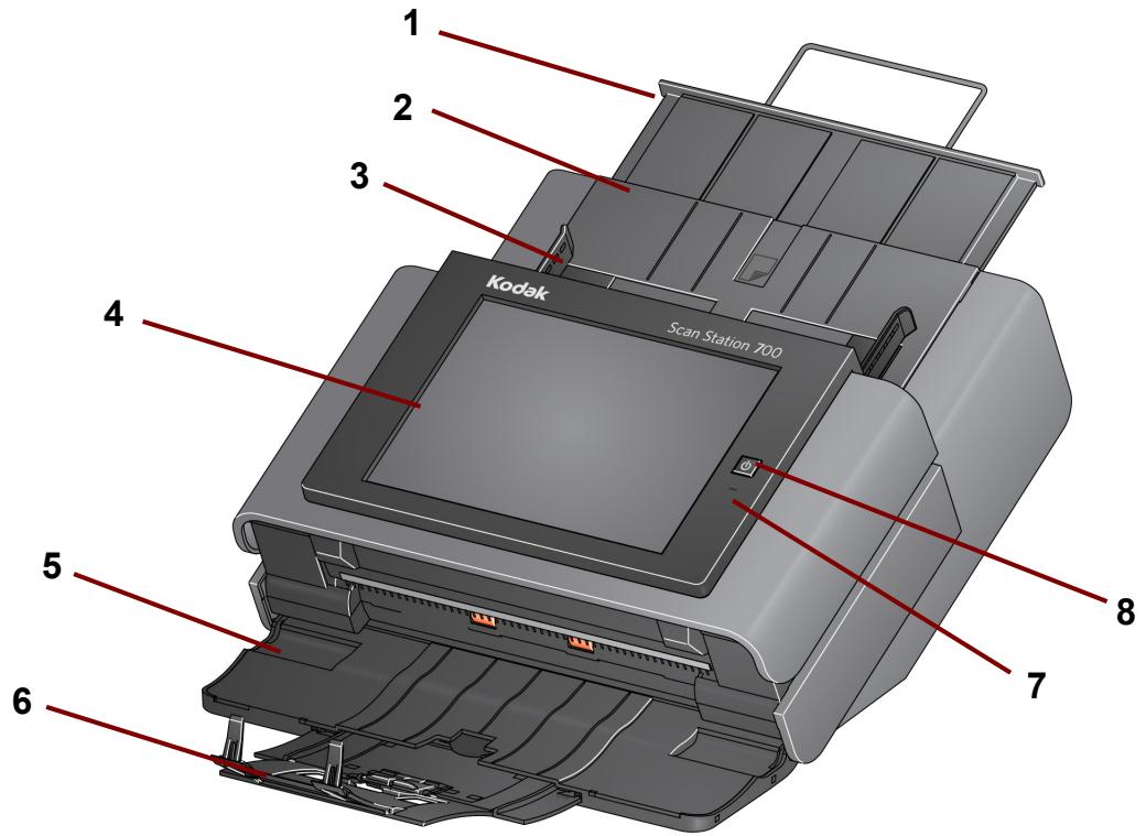
1 Input tray extender — pull this extender out to accommodate document sizes over 8 12 × 11 inches (A4).
2 Input tray - holds up to 75 sheets of 80g / m^2 (20 lb.) paper.
3 Side guides — slide the guides back and forth to accommodate the width of the documents you want to scan.
4 Touch screen — allows you to easily select a job or navigate through optional selections with a simple touch. The touchscreen is the primary user interface for interacting with the Scan Station.
5 Output tray panel — covers the transport when not in use. This panel must be open to scan documents. When opened, collects the scanned documents. The Scan Station cover cannot be opened when the output tray panel is closed.
6 Output tray extender — pull this extender out when scanning documents longer than 11 inches (28 cm).
7 Microphone - used for creating voice annotation.
8 Power — turns the power on. See "Indicator lights" on page 160 for more information.
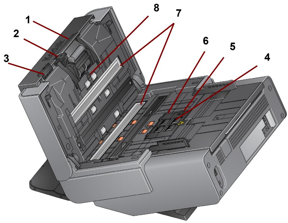
1 Separation module release lever/separation module — push the release lever down to remove the separation module for cleaning or replacement. The separation module provides smooth document feeding and separation of various sizes, thicknesses and textures of documents.
2 Gap release lever — allows you to manually adjust the space between the feed module and separation module for documents that require special handling.
3 Scan Station cover release lever — opens the Scan Station to allow access to the paper path for cleaning or clearing a document jam.
4 Feed module — provides smooth document feeding and separation of various sizes, thicknesses and textures of documents.
5 Paper present sensor — detects the presence of documents in the input tray.
6 Feed module cover — this cover needs to be removed when cleaning or replacing the feed module or feed module tires.
7 Imaging guides — for optimum image quality, keep the upper and lower imaging guides clean.
8 Multifeed detection sensor - detects if more than one document enters the paper path at a time.
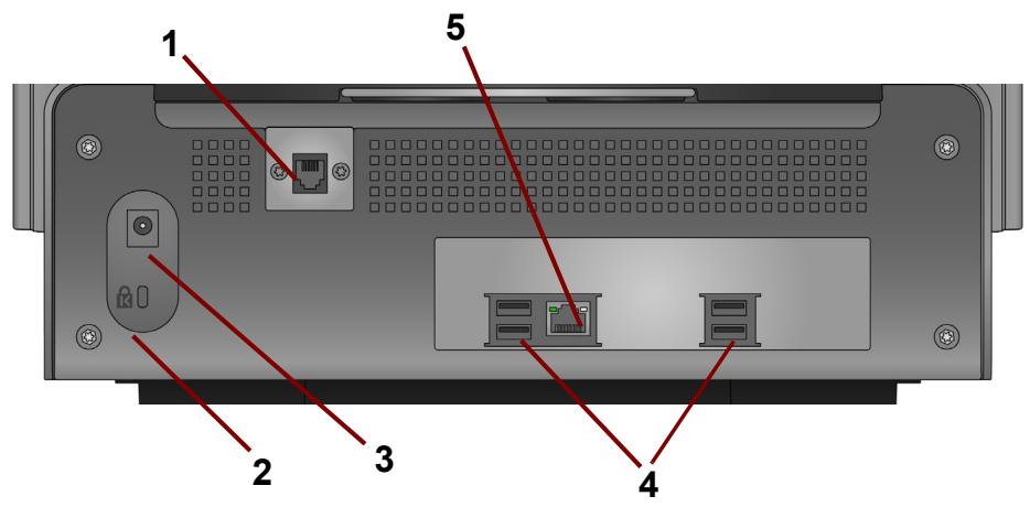
1 Modem port — the RJ-11 port connects the fax modem to a phone line. This port is present only for the Scan Station 730EX, and only for serial numbers earlier than 52190000.
2 Security lock port — connects a security lock to the Scan Station. You can purchase a standard security lock at an office supply store. Refer to the instructions provided with the security lock for installation procedures.
3 Power port - connects the power cord/adapter to the Scan Station.
4 USB ports — connects peripheral devices (e.g., keyboard, mouse and other accessories) to the Scan Station.
5 Ethernet port - connects the Scan Station to the network.
Network configuration details
Because the Scan Station is a network device, a basic knowledge of networking principles and terminology is helpful. You should be familiar with the concept of creating user accounts (on domains), sharing folders, setting access privileges, the Universal Naming Convention (UNC), using IP addresses, fully qualified domain names (FQDNs) and creating user groups.
NOTE: Some of the concepts covered in this section assume knowledge of Microsoft NT Domains and permissions. Refer to your documentation for Microsoft Windows Server 2003, 2008 or 2012 for more information.
Best practices
Scan Station user groups — for network domain environments, you should create a user group for all Scan Stations. This group will be used to hold account names that are assigned to each Scan Station. Minimally, there should be one account name that is assigned to each Scan Station. Optimally, each Scan Station should be assigned its own unique username and password and these accounts should be contained within a group that is reserved specifically for Scan Stations. These account names will be used when configuring the Scan Station's network settings and entered into theUsername, Password, and Network Domain fields.
NOTE: The Scan Station groups and login names must be given appropriate privileges to access the network resources that the user will see as Destination selections at the Scan Station.
Workgroup environments — for network environments that use the Microsoft "Workgroup" configuration, you may be required to create an account name and password to be assigned to Scan Stations. These account names will be used when configuring the Scan Station's network settings and entered into theUsername and Password fields. The Network Domain field should be left blank in Workgroup environments.
Network folders — it is recommended that you create network folders, for either Destination or Automatic Configuration Schedule updates, that can be accessed (minimally read, write, change access) by any Scan Station login account or by the user group created for Scan Stations.
UNC names for folders — you will need to know the fully qualified UNC name for each network folder that will be used by your Scan Station(s). When configuring network destinations, this will be the information entered into the Enter a complete directory path field on the Destinations screen. For example, you could create a folder called "scanfolder" on a server called "acmeserver" that would be reserved for Scan Station access. You would reference it by the following UNC name: \acmeserver\scanfolder.
NETBIOS usage — in network environments that use routers it is common practice to block NETBIOS traffic on your router. You may need to know the IP address of the server where you want to scan documents. By substituting the IP address of the server instead of the NETBIOS computer name, you can bypass the network traffic restrictions that may cause network scanning to fail. For example, the previously defined network address: \acmeserver\scanfolder should be replaced with something similar to: \192.168.2.10\scanfolder.
Pre-installation checklist
It is recommended that you review this checklist before configuring the Kodak Scan Station 710/730EX. This information is needed to create the initial configuration file to complete the installation. Locate any information you are unsure of before creating the configuration file. See your system or network administrator if you have questions about this information.
| Device Settings/IP Address The following settings are found using the Scanner tab and by selecting Scanner>Modify Scanner. | ||
| Parameter Name | Your Setting | Chapter Reference |
| Automatic (DHCP) | See “Modifying a Scan Station” on page 121. | |
| IP Address Settings — Static | ||
| Static (IPv4) IP Address | ||
| Subnet Mask | ||
| Default Gateway | ||
| Preferred DNS Server | ||
| Alternate DNS Server | ||
| Preferred WINS Server | ||
| Alternate WINS Server | ||
| Device Settings/Network Destination Credentials The following settings are found using the Configuration tab and by selecting Edit>Device Settings. | ||
| Parameter Name | Your Setting | Chapter Reference |
| Username, Password, Domain | • See “Best practices” on page 9 for creating an account for your Scan Station. • See “Configuring your device options” on page 33. | |
| Automatic Configuration Schedule | ||
| Device Settings/Email (SMTP) Server The following settings are found using the Configuration tab and by selecting Edit>Device Settings. | ||
| Parameter Name | Your Setting | Chapter Reference |
| Email Server Address | See “Configuring email settings” on page 38. | |
| Username, Password, Domain | ||
| Port | ||
| Authentication Scheme | ||
| Maximum Attachment Size | ||
| Security Type | ||
| Device Settings/Active Directory Server The following settings are found using the Configuration tab and by selecting Edit>Device Settings. | ||
| Parameter Name | Your Setting | Chapter Reference |
| Server Address | See “Configuring Active Directory Server settings” on page 41. | |
| Username, Password, Domain | ||
| Port | ||
| Base DN | ||
| Search Field Tag | ||
| Email Address Tag | ||
| Full Name Field Tag | ||
| Home Directory Tag | ||
| Fax Field Tag | ||
| Security Type | ||
| Device Settings/Fax The following settings are found using the Configuration tab and by selecting Edit>Device Settings. | ||
| Parameter Name | Your Setting | Chapter Reference |
| Outside Line Prefix | See “Configuring Fax settings” on page 43. | |
| Modem Country Code | ||
| LAN Fax Server Domain Name | ||
| Network Destination The following settings are found using the Configuration tab and by selecting Edit>Destinations. | ||
| Parameter Name | Your Setting | Chapter Reference |
| Complete directory path (the folder where you will put the scanned documents). | See “Setting up a network destination” on page 87. | |
| Printer Destination The following settings are found using the Configuration tab and by selecting Edit>Destinations. | ||
| Parameter Name | Your Setting | Chapter Reference |
| Complete directory path (the directory path to the printer server queue) | Chapter 7, “Setting up a printer destination”. | |
| Username, Password, Domain | ||
| Address (for direct connection to a printer) | ||
| Driver name (for direct connection to a printer) | ||
| Port name (for direct connection to a printer) | ||
| FTP Destination The following settings are found using the Configuration tab and by selecting Edit>Destinations. | ||
| Parameter Name | Your Setting | Chapter Reference |
| Server name and directory path | Chapter 7, “Setting up a FTP site”. | |
| Username, Password | ||
| Protocol (FTP) | ||
| Port number | ||
| Passive (Enable/Disable) | ||
| Proxy • Proxy Type • Proxy Address •Username • Password •Port Number | ||
| FTPS Destination The following settings are found using the Configuration tab and by selecting Edit>Destinations. | ||
| Parameter Name | Your Setting | Chapter Reference |
| Server name and directory path | Chapter 7, “Setting up a FTP site”. | |
| Username, Password | ||
| Protocol (FTPS) | ||
| Port number | ||
| Encryption | ||
| Passive (Enable/Disable) | ||
| SSL Server Certificate (Enable/Disable) | ||
| Proxy • Proxy Type • Proxy Address •Username • Password •Port Number | ||
| SFTP Destination The following settings are found using the Configuration tab and by selecting Edit>Destinations. | ||
| Parameter Name | Your Setting | Chapter Reference |
| Server name and directory path | Chapter 7, “Setting up a FTP site”. | |
| Username, Password | ||
| Protocol (SFTP) | ||
| Port number | ||
| Private Key File, Password | ||
| Proxy • Proxy Type • Proxy Address •Username • Password •Port Number | ||
| SharePoint Destination The following settings are found using the Configuration tab and by selecting Edit>Destinations. | ||
| Parameter Name | Your Setting | Chapter Reference |
| SharePoint website URL | Chapter 7, “Adding a SharePoint group”. | |
| Username, Password | ||
| Document Path | ||
| Index Fields | ||
| Certificate, Password | ||
| Proxy • Proxy Address •Username • Password •Port Number | ||
| Kofax Front Office Server Destination The following settings are found using the Configuration tab and by selecting Edit>Destinations. | ||
| Parameter Name | Your Setting | Chapter Reference |
| Kofax Front Office Server address | Chapter 7, “Adding a Kofax Front Office Server group”. | |
| Port number | ||
| Username, Password | ||
| Client ID | ||
| Shortcut Type | ||
| Shortcut Name | ||
| Index Fields | ||
| Certificate, Password | ||
Setup overview
Following is a list of things you need to do to prepare for configuring your Scan Station 710/730EX.
- Unpack your Scan Station(s) according to the unpacking instructions in the box that your Scan Station was packaged in.
- Setup the Scan Station and make the necessary connections. See the Installation Guide or "Setting up the Scan Station" on page 2.
- Review the pre-installation checklist in Chapter 2 and gather all of the information required to configure the Scan Station. Having this information available in advance will help ensure an easy Scan Station configuration.
- When the Scan Station is properly connected, press the power button and wait a few moments for the Scan Station to start up and display the application.
- Install the Kodak Scan Station 700 Series - Scanner Administration application on a separate PC. See "Installing the Kodak Scan Station 700 Series - Scanner Administration application" on page 21 for procedures.
Power saver mode and activating the Scan Station
By default, after 15 minutes of inactivity, the Scan Station will automatically enter into power saver mode.
To activate the Scan Station from power saver mode press the power button.
Setup Wizard
When the Scan Station is turned on for the first time, the setup wizard automatically starts. It provides a step-by-step procedure allowing you to select configuration options (i.e., time, date, etc.) when connecting to the network.
Other configuration options are also required for Scan Station setup (i.e., email and fax configurations, etc.); however, these options are setup using the KSS700 - Scanner Administration application.
Procedures regarding these additional settings are explained in more detail later in this chapter.
NOTES:
- The procedures that follow are only for the first time you turn on your Scan Station.
- For detailed information regarding any of the following settings, see the section entitled, "Configuring your Scan Station" later in this chapter.
-
If Run the wizard at next boot-up is enabled, the wizard will start at the next power up.
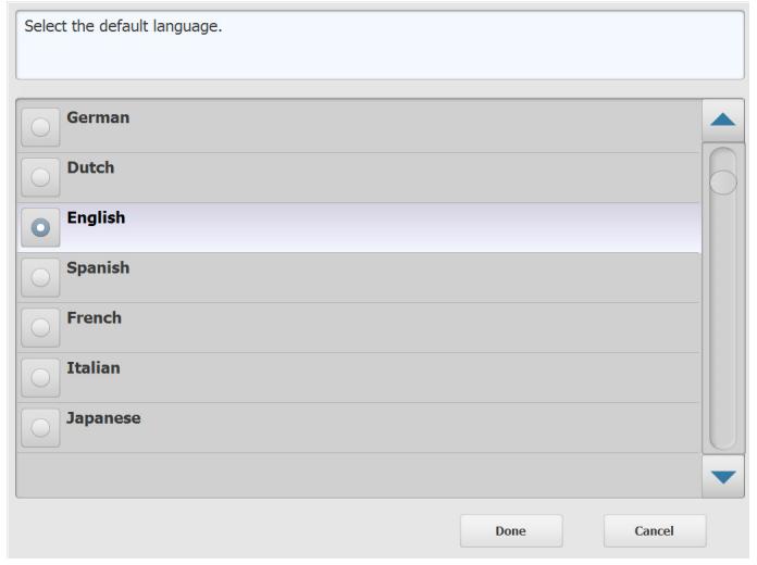
-
Upon startup the Language screen will be displayed. Select the language that you want the Scan Station user interface to be display in, then click Done.
- The following screen will be displayed. Select any of the options you want to configure:
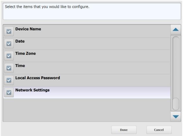
Device Name: allows you to enter the device name.
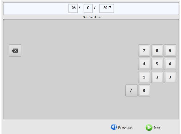
- Date: allows you to set the date on the Scan Station.
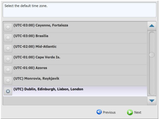
- Time Zone: allows you to select the desired time zone.
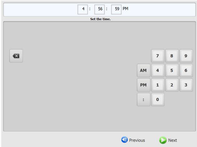
- Time: allows you to set the time on the Scan Station.
- Local Access Password: allows you to set a password that provides access to the Scan Station. (See “Configuring your device options” on page 33 for more information about the Local Access Password.)
Network Settings: allows you to configure the Scan Station's network address.
After you select the options you want to configure, click Done and the screen associated with the first selected option will be displayed.
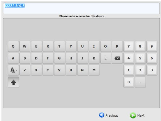
- If you selected Device Name, a keyboard will be displayed. Enter the name of the device then click Next.
- If you selected Date, the Date screen will be displayed. Enter the desired date and click Next.
- If you selected Time Zone, the following screen will be displayed. Select the desired time zone and click Next.
- If you selected Time, the following screen will be displayed. Enter the desired time and click Next.
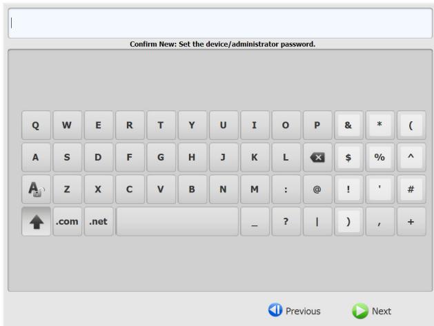
- If you selected Local Access Password, the following screen will be displayed. Enter the desired password and click Next.
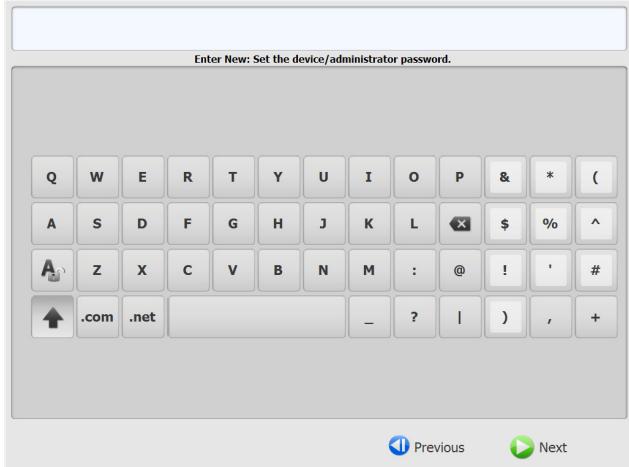
- The password confirmation screen will be displayed. Enter the password again and click Next.
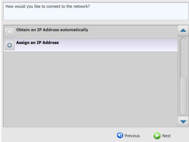
- The following screen will be displayed. Select Obtain an IP Address automatically to use DHCP to obtain an IP address to connect to the network, or Assign an IP Address to enable you to enter the desired IP address. Click Next..
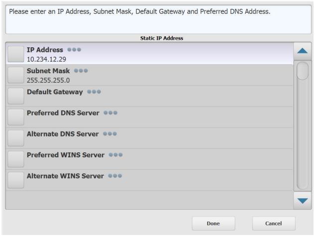
- The following screen will be displayed. Enter the required IP Address, Subnet Mask, Default Gateway, and Preferred DNS Server information. Click Done.
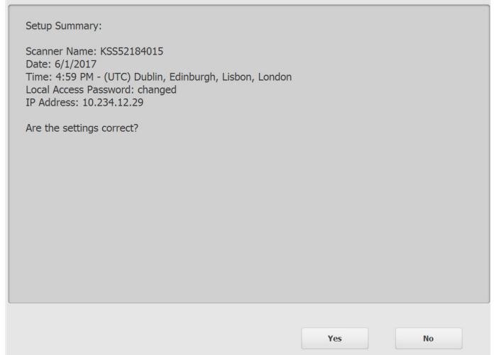
- The information will be processed. A screen summarizing your settings will be displayed. Click Yes to accept your selections.
- When all desired setting have been made, continue with the Scan Station installation. See the next section, "Installing the Kodak Scan Station 700 - Scanner Administration application".
Installing the Kodak Scan Station 700 Series - Scanner Administration application
You must install the Kodak Scan Station 700 Series - Scanner Administration application on a host PC. The Kodak Scan Station 700 Series - Scanner Administration application allows you to properly setup, configure and manage Scan Station 700/710/720EX/730EX/500/520EX devices over a network in an efficient and productive manner. This application communicates with Kodak Scan Station 500 and 700 devices over the network; thereby minimizing the need for individual access to multiple Scan Stations.
- Insert the Installation CD titled, "Scanner Administration and Supporting Documentation" in the CD-ROM drive on the computer where the Kodak Scan Station 700 Series - Scanner Administration application will be installed. The installation software starts up automatically.
NOTE: If .NET Framework 4.0 is not already installed, the Kodak Scan Station 700 Series - Scanner Administration application installer will install them before installing the Kodak Scan Station 700 Series- Scanner Administration application.
- Click Next when the Kodak Scan Station 700 Series splash screen is displayed.
- Click Next when the Welcome screen is displayed.
- Click I Agree after you have read and agreed with the terms of the Software License Agreement, then click Next.
The Ready to Install Program screen will be displayed.
- Click Install to continue.
- After the Kodak Scan Station 700 Series - Scanner Administration application has been installed, click Finish.
- Remove the Installation CD from the CD-ROM drive.
- After installing and running the application, the Kodak Scan Station 700 Series - Scanner Administration main screen will be displayed.
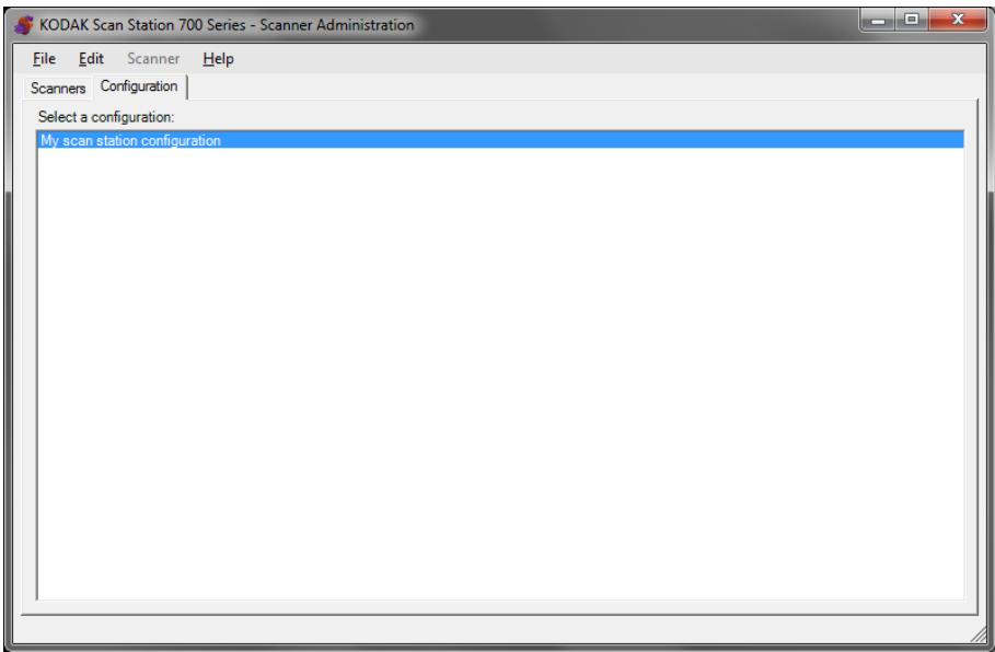
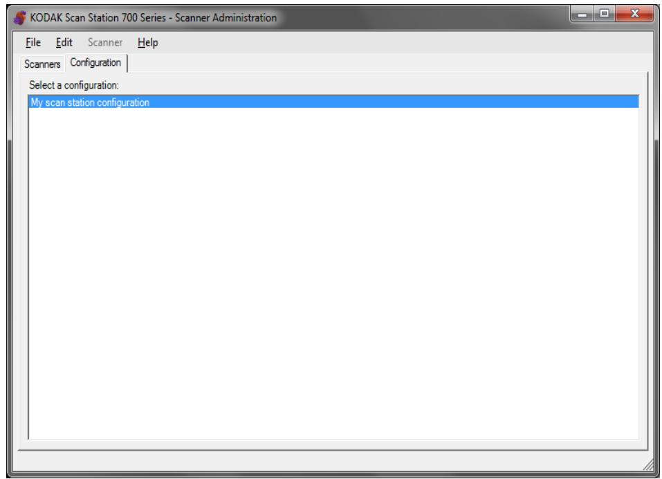
The main screen
The main screen provides two tabs:
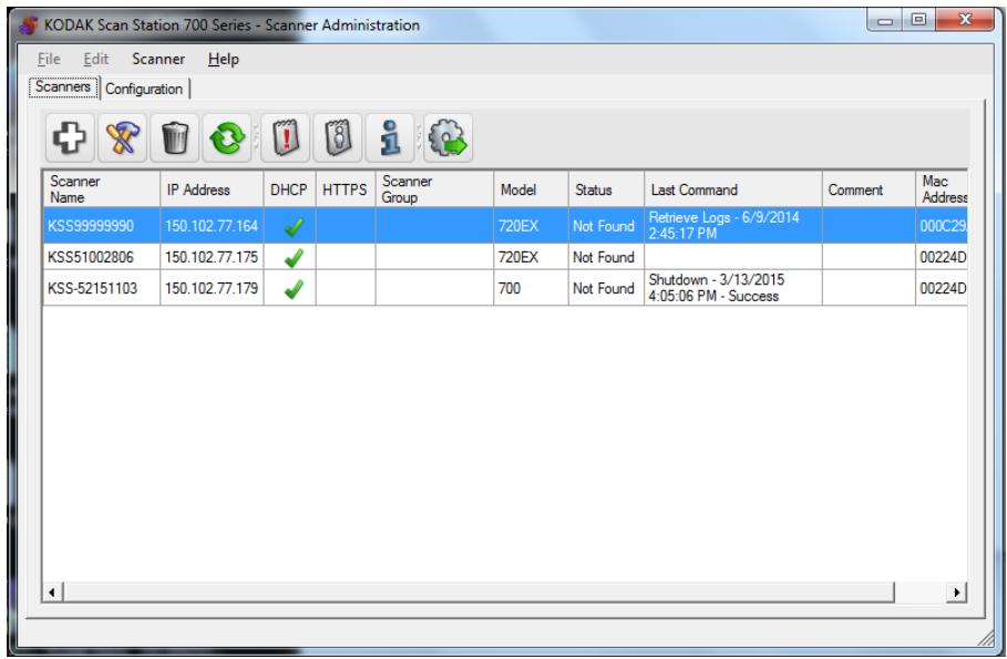
- Scanners tab — allows you to monitor any Scan Stations that have been discovered and configured. See "Chapter 10 Monitor and Manage Your Scan Stations" on page 115 for more information.
NOTE: In addition to the Scan Station 710/730EX, the Kodak Scan Station 500/520EX/700/720EX can be managed from the Scanner tab and the Scanner menu.
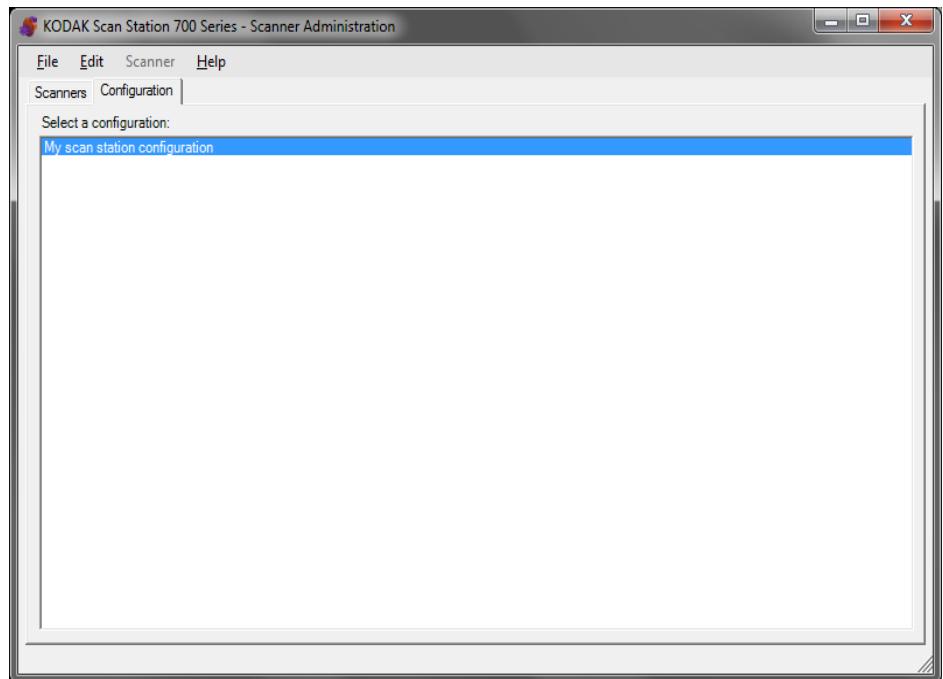
- Configuration tab — allows you to configure and set up your Scan Stations. This screen will be displayed with a list of your previously created configurations.
NOTE: The Configuration tab and the File and Edit menus only apply to the Scan Station 700/710/720EX/730EX.
The Scan Station 500/520EX must be configured using the Kodak Scan Station Configuration Organizer. See your Administrator's Guide for the Kodak 500/520EX for more information.
A configuration is a collection of Device settings, Scan settings, Index Templates, Destinations, Groups, and Job settings. Configurations are stored on your PC in a configuration database and maintained by the Kodak Scan Station 700 Series - Scanner Administration application. Detailed procedures for configuring these settings are described in Chapters 4-9.
Menus
The File, Edit, Scanner and Help menus are available from the Kodak Scan Station 700 Series - Scanner Administration main screen.
NOTE: When the Configuration tab is selected, only the File, Edit and Help menus are available.
When the Scanners tab is selected, only the Scanner and Help menus are available.
File menu
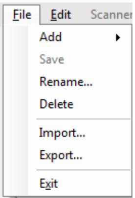
Following is a description of the menu options on the File menu.
Add - allows you to create a new configuration from the default or from an existing configuration.
- From default configuration: when selected, displays the Device Settings screen with a default configuration. For more information see "Device Settings" on page 31.
- From selected configuration: when selected, displays the Configuration Name screen which allows you to name a new configuration which is based on the currently selected configuration. If you want to base a new configuration on an existing one (not the default), select an existing configuration, then select File>Add>From the selected configuration. If there are no configurations (other than the default), this option is grayed out.
Save — saves the selected configuration to the configuration database located on the PC running the Kodak Scan Station 700 Series - Scanner Administration application. This option is only available for configurations that have changed (marked with an asterisk).
Rename — displays the Configuration Name screen allowing you to rename the selected configuration.
Delete - deletes the selected configuration.
Import - allows you to import a configuration file from any location to the Kodak Scan Station 700 Series - Scanner Administration application.
Export - allows you to export a configuration file from the Kodak Scan Station 700 Series - Scanner Administration application to any location.
Exit — closes the Kodak Scan Station 700 Series - Scanner Administration application.
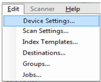
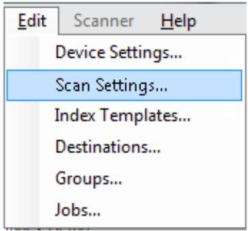
Edit menu
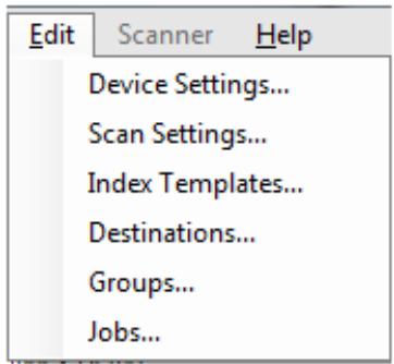
Following is a description of the menu options on the Edit menu.
Device Settings — allows you to configure the parameters that the Scan Station needs to send emails, communicate with an Active Directory Server for security purposes, set Scan Station defaults and configure fax settings. For more information, see “Device Settings” on page 31.
Scan Settings — allows you to set basic image processing settings, such as, color/grayscale/black and white, output file format, compression, and advanced options like Hole Fill, Streak Filter, etc. For more information, see “Scan Settings” on page 51.
Index Templates — allows you to define bar code and OCR areas on a document that can then be used to dynamically construct a file path name for saving scanned documents. For more information, see "Chapter 6 Index Templates" on page 65.
Destinations — allows you to add or modify destinations (e.g., email, network folder, printer, FTP site, etc.) that define where the scanned output will be sent. For more information, see “Chapter 7 Create Destinations” on page 81.
Groups — allows you to create or modify a group of users from an Active Directory Server. Other users that are not in an Active Directory Server group can also be added. For more information, see "Chapter 8 Add and Manage Groups" on page 103.
Jobs — allows you to create or modify jobs which are a collection of scan settings, index templates, destinations and groups of users. For more information, see "Chapter 9 Create Jobs" on page 109.
Scanner menu
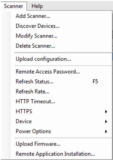
Following is a description of the menu options on the Scanner menu. Refer to "Chapter 10 Monitor and Manage Your Scan Stations" on page 115 for more information and procedures regarding these options.
Add Scanner — displays the Add Scanner dialog box, which allows you to register Scan Stations that you want to manage remotely.
Discover Devices — allows you to scan a range of IP addresses and automatically register any Scan Station within that range that responds to the request.
NOTE: Any Scan Station that has previously had its Remote Access Password set will not respond to the discovery request. If this is the case, you will need to manually add the Scan Station by selecting Scanner>Add Scanner and enter the Scan Station's name or IP address and the Scan Station's password.
Modify Scanner — allows you to rename the selected Scan Station and configure network settings.
Delete Scanner — deletes the selected Scan Station(s) from the list of administered Scan Stations.
Upload configuration — sends the configuration to the selected Scan Stations.
NOTE: If the Scan Station is in power saver mode, you can select Scanner>Upload configuration to wake up the Scan Station.
Remote Access Password — displays the Remote Access Password dialog box which allows you to change the network connection password to the Scan Station.
This password is used by the Kodak Scan Station 700 Series - Scanner Administration to communicate with the Scan Station. An organization can have more than one instance of the Scanner Administration software running at one time. Only those instances that are aware of the password for a particular Scan Station can communicate with that Scan Station. If a Scan Station with a Remote Access Password is deleted from the grid view, the password will be required to add the Scan Station back to the grid view. For more information, see "Grid view" on page 117.
Refresh Status — displays the current state of the selected Scan Station(s):
- Idle — the Scan Station is currently active on the network; but not in use.
NOTE: Any user interaction using the touch screen will put the Scan Station into the In Use state (see below).
- Scanning — Scan Station is scanning.
- Processing images — the Scan Station is processing images (e.g., converting images to PDF).
- Sending email — the Scan Station is sending an email.
- Saving — images are being saved to a USB drive, network folder, FTP site, or a SharePoint site.
- Printing - the Scan Station is printing images using a remote printer.
- Scan Completed — the Scan Station has successfully completed the scanning session. When Done is selected on the Scan Station, the Scan Station will go into the Idle state.
- Error — the Scan Station failed to complete the scanning session. When Done is selected on the Scan Station, the Scan Station will go into the Idle state.
- Cancelled — the scanning session has been cancelled. After the inactivity time period has been reached, the Scan Station will go into the Idle state.
Preview - the Scan Station Preview feature is in use. - Sending Fax — the Scan Station is sending a fax. This is only displayed if the Scan Station is not currently scanning.
- Receiving Fax — the Scan Station is receiving a fax. This is only displayed if the Scan Station is not currently scanning.
- Powering down — the Scan Station is in the process of a power-down sequence.
-
Rebooting — the Scan Station is in the process of being restarted.
-
Updating — the configuration file or firmware is currently being updated.
- In Use — when a USB flash drive is inserted, a user is logging in or is interacting with the Scan Station, this state is displayed.
- Not found — the Scan Station cannot be found on the network (e.g., power is turned off).
Refresh Rate — allows you to set the frequency that the application will try and communicate with all Scan Stations.
HTTP Timeout — allows you to adjust the amount of time (in seconds) that the HTTP commands have to complete. If some commands timeout and do not complete, adjust this to a higher value.
HTTPS — turning HTTPS on will encrypt data as it is communicated between the Kodak Scan Station 700 Series - Scanner Administration application and the Scan Station.
Device — provides the following options. Procedures on how to use these functions are described in Chapter 10, Monitoring and Managing Your Scan Stations.
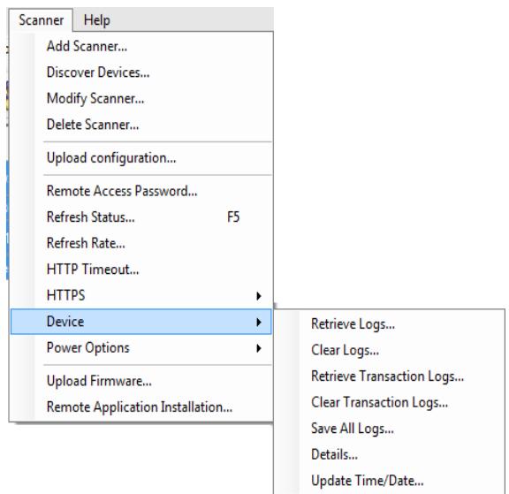
- Retrieve Logs: allows you to save the log files retrieved from the selected Scan Station.
- Clear Logs: when selected, the following message will be displayed, Are you sure you want to clear the log files of the selected scanner? If you click Yes, the log files will be cleared.
- Retrieve Transaction Logs: allows you to save the transaction log file retrieved from the selected Scan Station
- Clear Transaction Logs: when selected, the following message will be displayed, Are you sure you want to clear the transaction log files of the selected scanner? If you click Yes, the transaction log files will be cleared.
-
Save All Logs: saves all available log files found on the selected Scan Stations and saves them to the selected directory. The logs will be saved in the selected directory under the Device Name folder of the Scan Station.
-
Details: provides device information about the selected Scan Stations including network configuration, software versions and page count.
- Update Time/Date: allows you to set the NTP time server for all selected Scan Stations.
Power Options — provides options for restarting and turning off the selected Scan Stations.
Upload Firmware — displays the Open dialog box which allows you to upload new firmware updates to the Scan Station.
Remote Application Installation — allows you to download a third party application.
Help menu
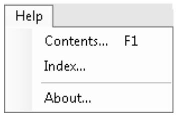
Following is a description of the menu options on the Help menu.
Contents — provides help topics for the Kodak Scan Station 700 Series - Scanner Administration.
Index — provides help topics for the Kodak Scan Station 700 Series - Scanner Administration.
About — displays the About screen for the Kodak Scan Station 700 Series - Scanner Administration application, which provides information about the current version of the software.
Icons
The information in Chapters 4-9 outline a step-by-step procedure for setting up your Scan Stations. Most screens have one or more of the following icons.

Creates a new entity.

Edits an existing entity.

Deletes the selected entity.

Displays the current state of the Scan Station:
- Idle
- Scanning
- Processing images
- Sending email
- Saving
- Printing
- Scan Completed
- Error
- Cancelled
Preview - Sending Fax
Receiving Fax - Powering down
Rebooting - Updating
In Use
Not found

Retrieves, displays and allows the saving of the log file on the selected Scan Station.

Displays and allows the saving of the transaction log file on the selected Scan Station.

Displays detailed information about the selected Scan Station (e.g., software version, IP address, etc.).

Allows you to send the selected configuration to the Scan Station. This option is grayed out if no Scan Stations are accessible by the Kodak Scan Station 700 Series - Scanner Administration application.
Device Settings
The Device Settings option allows you to configure the Scan Station for sending emails, sending and receiving faxes, communicating with the Active Directory Server for authentication purposes, creating index templates and setting up Scan Station defaults.
To set up a configuration:
- Select the configuration that you want to apply settings to or create a new configuration (File>Add).
- Select Edit>Device Settings.
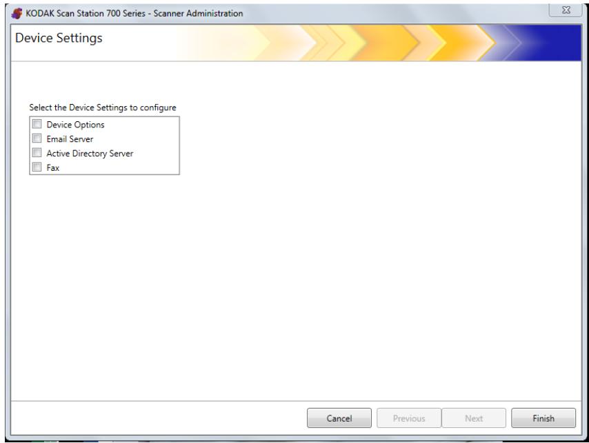
Check all options that you want to configure and click Next. The software will step you through each option.
Device Options - allows you to set the following options:
- Language
- Local Access Password
- Network Destination Credentials
- Network Information
Automatic Configuration Schedule - Volume
- Configuration Options
- Date and Time
-
Power Saver
-
Email Server — for the Scan Station to send documents to email recipients, you must define how the Scan Station will access your email server (e.g., SMTP, Return Email Address, etc.).
- Active Directory Server — allows you to configure your connection to the Active Directory Server which allows the Scan Station to authenticate credentials and look up specific user information, such as their home directory on the network.
- Fax — allows you to configure the Scan Station to send and receive faxes.
Configuring your device options
This screen allows you to setup the following device options:
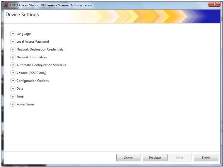
Language — click the down arrow to select the language that will be used on the Scan Station display.

Language
Language:
English
Local Access Password — allows you to set a password that controls administrator access to the Scan Station.

Local Access Password
Password:
Confirm new password:
| Force User Login | Local Access Password Set | Local Access Password Blank (default) |
| On | The user must login into the Scan Station with their user name and password. The local access password is required to update the Scan Station if a user inserts a USB drive containing a configuration file. | The user will login into the Scan Station with their user name and password. No password is required to update the Scan Station if a USB drive containing a configuration file is inserted. |
| Off | Local access password is required to apply a configuration file at the Scan Station with a USB flash drive containing a configuration file. | No access control. |
| It is recommended that a local access password be set to guard against a non-privileged user from gaining access to administrator functions. | ||
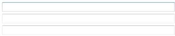
Network Destination Credentials — when selected, define theUsername, Password and Domain required to access network resources.

Network Destination Credentials
Username:
Password:
Domain:
NOTE: This is only used for network folders when Force User Login (on the Active Directory Server screen) is not enabled.
- Enter the network user name assigned to the Scan Station. For more information see "Network configuration details" on page 9.
NOTE: If you want the Scan Station to have access to network printers or network shared folders, the credentials provided must have sufficient privileges to access these resources. - Enter the password for the network user name in the Password field.
NOTE: This password is only used by the Scan Station and will never be displayed in readable form. The password is stored in encrypted format. - Enter the Microsoft network domain name which the Scan Station will be connected to in the Domain field. In a workgroup environment, this field can be left blank.
Network Information — allows you to define DNS suffixes to search for name resolution.

Network Information
DNS Suffixes (comma separated):

Automatic Configuration Schedule — the Scan Station can be configured to look for firmware updates and an updated configuration on specific days and times. Select this option to allow your Scan Station to automatically look for an updated configuration.

Automatic Configuration Schedule
Folder:
Day(s):
Time of Day:
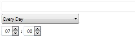
- Enter a network folder where the Scan Station will find updated configuration settings.
- Select which day(s) of the week this operation will be performed.
- Select the time of day you want your Scan Station to check for
updates.
NOTE: When updating a configuration using this method, the fields on the Add Scanner and Modify Scanner dialog boxes will not be updated: Scanner Name, IP Address and Remote Access Password.
Volume (SS500 only) — allows you to adjust the master volume of the Scan Station 500. This will affect the speaker sound from the FAX modem and voice annotation playback.
Volume (SS500 only)
Volume
NOTE: If you do not hear the fax dial tone after changing the volume, you may need to restart the Scan Station.
Configuration Options — provides the following options
Configuration Options
Select the items below that you want to restrict access to or enable:
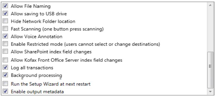
- Allow File Naming — if enabled, allows a user to configure file name options on both the Scan Station and the Kodak Scan Station 700 Series - Scanner Administration.
- Allow Saving to USB drive — allows you to enable scanning to a USB drive. This may be useful in more secure environments where tighter control is required.
- Hide Network Folder location — enable this option to provide a more secure environment by partially hiding the location of the network folder. If this option is enabled, only the end of the network folder path will be displayed on the Scan Station touchscreen. For example: \server\myfolder will be displayed as: ...\myfolder.
-
Fast Scanning (one button press scanning) — allows a user to scan instantly without waiting for the 10-second delay, the Settings Review screen or the Destination Review screen to be displayed. A message will only be displayed if the scan session was unsuccessful.
-
Allow Voice Annotation — when enabled, allows a user to record a voice annotation for each batch of scanned documents. By default, this option is enabled.
- Enable Restricted mode (users cannot select or change destinations) — when enabled, will only allow users to select a predefined job from the Scan Station touchscreen. These jobs cannot be changed by the user.
- Allow SharePoint index field changes — when enabled, allows a user to change existing index fields.
- Allow Kofax Front Office Server index field changes — when enabled, allows a user to change existing index fields.
- Log all transactions — the Scan Station can log all transactions (all activity related to login, scanning and saving to destinations) to a separate transaction file. This file is in XML format and can be downloaded from the Scan Station. This is useful in environments that are security-minded or where transactions are used for billing. By default, all transactions are logged (checked). You can disable transaction logging by unchecking the checkbox.
- Background processing — allows you to select how jobs are processed. If background processing is selected, all jobs will be submitted to a queue and, by default, be processed in a first in, first out (FIFO) manner. This allows a user to start a second scan job immediately after the first job is scanned, even if the first scan job is still being processing.
- Run the Setup Wizard at next restart — when selected, the Setup Wizard will run when the Scan Station restarts, which provides a step-by-step procedure allowing you to select configuration options (e.g., time, date, etc.) when the Scan Station is restarted.
NOTE: The Setup Wizard is run from the Scan Station (not the Kodak Scan Station 700 Series - Scanner Administration application).
- Enable output metadata — with each document scanned, a .xml file will be created and sent to the destination along with the scan file. A .xsd file that can be used for metadata verification is on the Installation CD.
- Allow email selection in Jobs mode — allows you to display all of the email destinations that are configured for a Job along with the ability to add additional email destinations using an Active Directory search. This option only works in Jobs mode and appears after the Job begins.
Date — allows you to set the date format on the Scan Station.
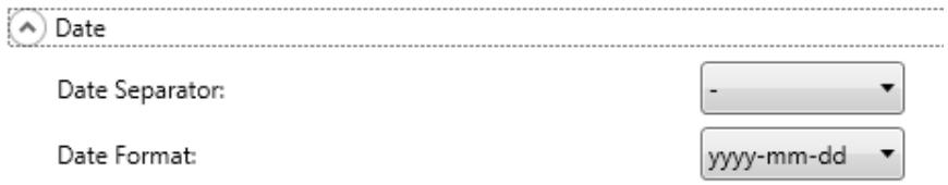
- From the Date Separator drop-down list, select a symbol to use as a separator in the date format.
- Select how you want the date displayed on the Scan Station touchscreen by selecting a format (year, month, day) from the Date Format drop-down list.
Time - allows you to set the time format on the Scan Station.
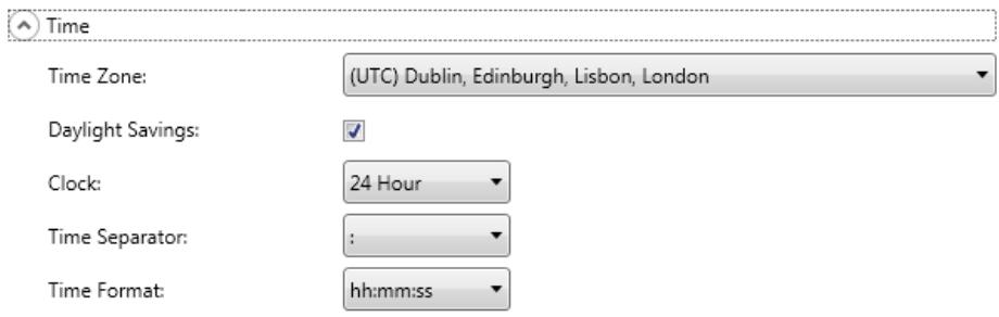
- Select the Time Zone based on the Scan Station's location.
NOTE: If Scan Stations are located in different time zones, separate configuration files will be necessary.
- If you want the Scan Station to automatically adjust for daylight savings time, check the Daylight Savings check box.
- Select either 12 Hour or 24 Hour time format from the Clock dropdown list.
- Select the desired separator symbol that will be displayed in the time format from the Time Separator drop-down list.
- Select the hours, minutes, seconds of how you want the time format to be displayed: hh:mm:ss, h:mm:ss, hh:mm or h:mm.
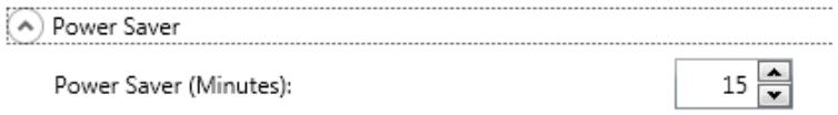
Power Saver — use the up and down arrows to set the amount of time the Scan Station needs to be inactive before it goes into power saver mode. The default is 15 minutes.
Depending on the options you selected on the main Device Settings screen, you will have the option of clicking Next which will display the next device you want to configure, or Finish which will return you to the Configuration tab.
For the Scan Station to send documents to email recipients, you must define how the Scan Station will access your email server.
1. Check Email Server and click Next.
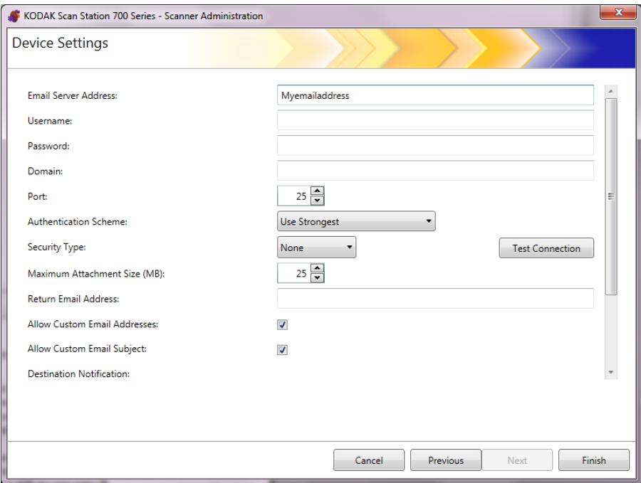
- Enter an IP address or a fully qualified domain name of your SMTP server in the Email Server Address field.
- If your SMTP server requires it, enter aUsername, Password and an optional Domain name for the email server account that the Scan Station will log into.
- Most email servers communicate on port 25. If your email server communicates on a different port, select the desired port number.
- Select Authentication Scheme to select the specific SMTP Authentication Scheme used by your email server. Select from the following options:
Use Strongest
None
Plain
- Login
- MD5 Challenge Response
NTLM
NOTE: Use Strongest will select the strongest available authentication scheme reported by the email server. For more information on authentication schemes, consult your network administrator.
-
Use the up and down arrows to select the desired Maximum Attachment Size of an email attachment that can be sent successfully (1 to 99 MB in 1 MB increments).
-
Enter the email address where you want a notification to be sent that an email could not be delivered by the Scan Station in the Return Email Address field. This email address will also be put in the From field on the email.
-
If you want the user to have the ability to enter an email address that is not currently in the address book, check the Allow custom Email Addresses checkbox.
-
If you want the user to have the ability to enter information in the subject line when scanning to email destinations, check the Allow custom Email Subject checkbox.
-
Select the security type to setup a secure connection to your email server. Selections are: None, SSL or Use StartTLS.
-
SSL: select this option if your email server requires Secure Socket Layer (SSL).
- Use StartTLS: select this option if you want to enable a secure SMTP connection.
NOTE: If selected, make sure your email server is configured to use StartTLS. If it is not, the Scan Station will fail to send an email.
- If email notifications of success or failure are required, you can make a selection in the Destination Notification fields.
| Destination Notification: | |
| Email Address: | |
| Prompt for Email Address: | ✓ |
| Success: | ✓ |
| Failure: | ✓ |
- Email Address: enter the email address for the destination notifications. If there is an entry in this field, and the user also enters a notification email address before scanning, the notification will go to both email addresses.
- Prompt for Email Address: if checked, the user can enter a notification email address before scanning.
- Success: if checked, an email notification will be sent whenever a destination is successful.
- Failure: if checked, an email notification will be sent whenever a destination was not delivered successfully.
NOTES:
- Email destination notifications are sent only when Background Processing is enabled.
- If Success and Failure are both unchecked, an email notification will not be sent.
- If Success is checked and you are outputting to several destinations, you will only receive a success notification if all the destinations were successful. If any one of them fails, a notification will not be sent.
- If Fast Scanning is enabled, the user cannot enter a notification email address before scanning.
- If the Email Address field is set and the user enters a notification email address before scanning, notifications will be sent to both email addresses.
- For email destinations, the notification message, "Email message(s) have been queued" will be displayed.
- For fax destinations, the notification message, "Fax(s) have been queued" will be displayed.
- Email destinations use the Return Email Address field in the Email Server settings when an email cannot be delivered.
-
Fax destinations use the Fax Notification Email Address field in the Fax settings when a fax cannot be delivered.
-
Click Test Connection if you want to check to be sure your settings are correct. When finished, a Success or Failure message will be displayed. If the test connection failed, verify that all of your settings are correct and make any necessary changes, until a Success message is displayed.
NOTE: You may need to use the scroll bar to access the Test Connection button.
Depending on the options you selected on the main Device Settings screen, you will have the option of clicking Next which will display the next device you want to configure, or Finish which will return you to the Configuration tab.
Configuring Active Directory Server settings
If you selected to configure the Active Directory Server, proceed with the following steps. If not, go to the section that describes the next device you want to configure.
The Active Directory Server allows you to setup a central location for network administration and security.
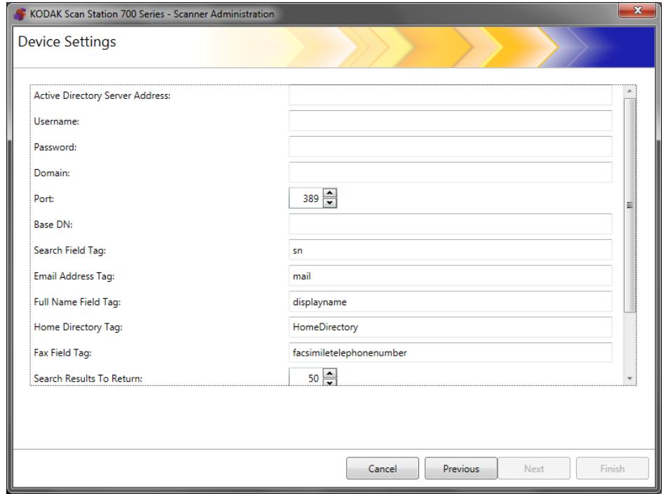
- Enter an IP address or a fully qualified domain name in the Active Directory Server Address field.
- If your server requires it, enter aUsername, Password and an optional Domain name for the Active Directory Server account that the Scan Station will log into.
- Most Active Directory Servers communicate on port 389. If your Active Directory Server communicates on a different port, select the desired port number.
- The Base DN (Distinguished Name), Search Field Tag, Email Address Tag, and Full Name Field Tag are strings that define the search criteria for the Active Directory Server. See your network administrator for the specific format of these strings. When you have the correct format, enter the Base DN, Search Field Tag, Email Address Tag and Full Name Field Tag.
- In the Home Directory Tag field enter the name of the tag in your Active Directory Server that defines where the user's home directory is located. This requires the home directory to be defined in your Active Directory Server database.
If Force User Login is checked, when the user logs into the Scan Station, their home directory will automatically be used as their destination.
- Enter the Active Directory Server Fax Field Tag for the tag to use when searching the Active Directory Server for fax numbers. For more information, contact your network administrator for the exact string to use (e.g., facsimiletelephonenumber).
- Select the maximum number of records to display when performing a search from the Search Results To Return field. Select a number from 1 to 1000.
NOTE: You may need to use the scroll bar to access the Security Type, Force User Login and the Test Connection options.
-
Select the Security Type to setup a secure connection to your Active Directory Server. Selections are: None, SSL or TLS.
-
If you select SSL or TLS, the Certificate and Certificate Password fields will be displayed allowing you to select a certificate file.
-
Some certificates require a password. If your certificate requires a password, enter the password.
-
If you check Force User Login, it requires the user to login before beginning a scan session. At login, the user will have to enter a user name, password and domain. These credentials will be used to access network resources.
NOTE: A default administrator account is available for logging onto the Scan Station after enabling Force User Login. Initially the Local Access password will be "blank" and it is up to you to set this password to prevent user access to administrative functions. For information on this Local Access password, see "Configuring your device options" on page 33.
- Check User Home Directory to have the Scan Station automatically create a destination for the logged in user's home directory (which is extracted from Active Directory). This can be enabled if Force User Login is checked.
- Check User Email Address to have the Scan Station automatically create an email for the logged in user (which is extracted from Active Directory). This can be enabled if Force User Login is checked.
- Check Allow Email Search to allow the user to do email searches on the Scan Station when sending to email destinations.
- Click Test Connection if you want to check to be sure your settings are correct. When finished, a Success or Failure message will be displayed. If the test connection failed, verify that all of your settings are correct and make any necessary changes, until a Success message is displayed.
Depending on the options you selected on the main Device Settings screen, you will have the option of clicking Next which will display the next option you want to configure, or Finish which will return you to the Configuration tab.
Configuring Fax settings
Email to fax is available for all Scan Station 700 series scanners.
If you have a Scan Station 730EX with a modem1, fax settings can be configured to allow the Scan Station to send and receive faxes.
Email to fax
If you use an email-to-fax service (e.g., Nextiva), fax settings can be configured to allow the Scan Station to send email of scanned images to fax destinations over a Local Area Network (LAN).
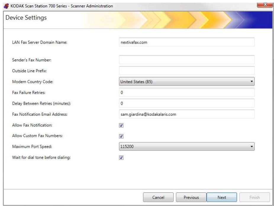
1. Enter the LAN fax server domain name.
NOTE: This option works only for an email-to-fax service sending to a fax number on a domain where no login is required.
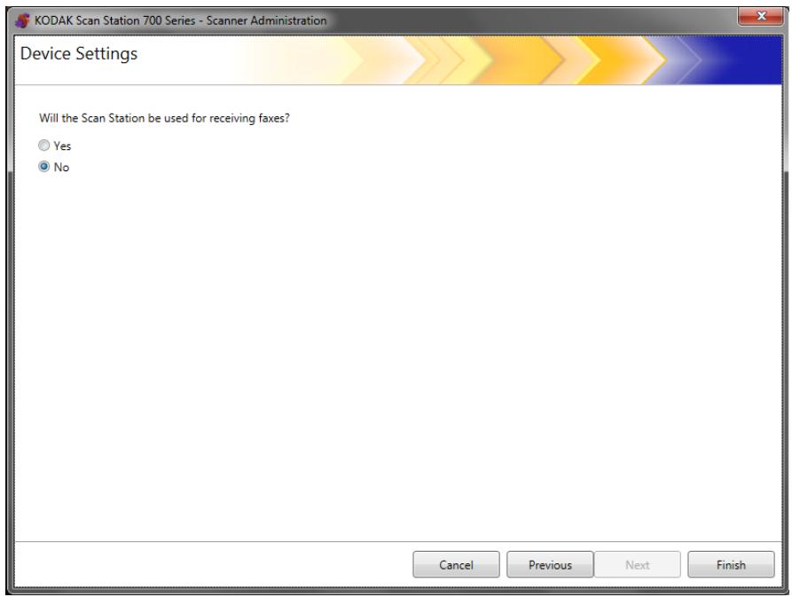
- If your Scan Station does not have a modem, click Next. The following screen will be displayed. Click No — you will not be receiving faxes if your scanner has no modem.
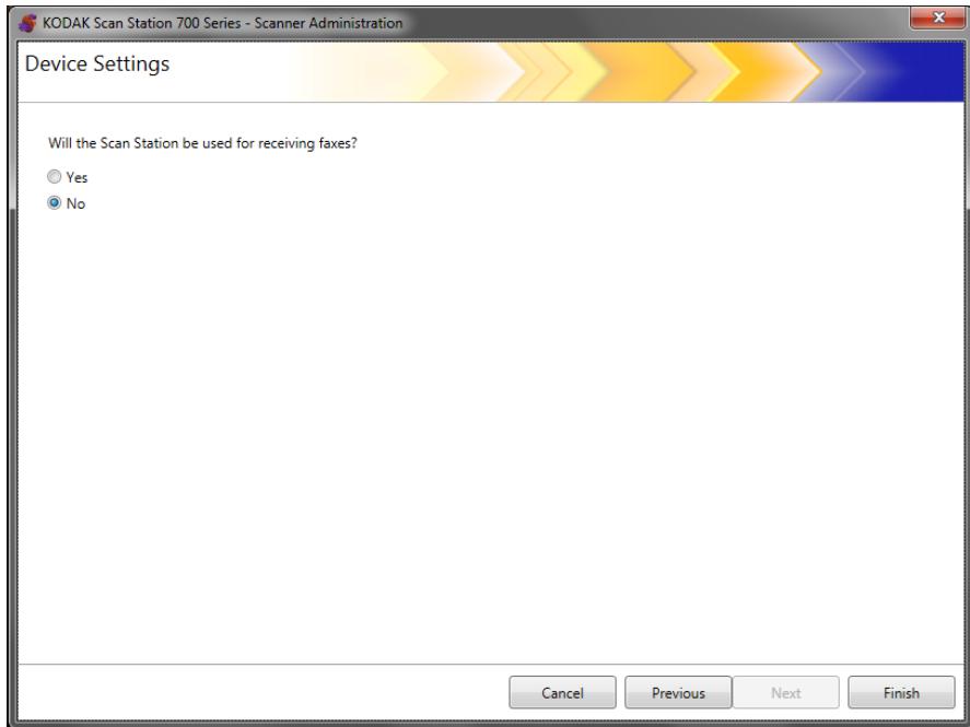
3. Click Finish.
NOTE: If your Scan Station does not have a modem, you should ignore the remainder of this chapter. Configuration settings to send and receive faxes will work only for Scan Stations with modems.
Sending faxes from the Scan Station 730EX
- In the Device Settings screen, enter a fax number in the Sender's Fax Number field. This number will be displayed on the banner of outgoing faxes.
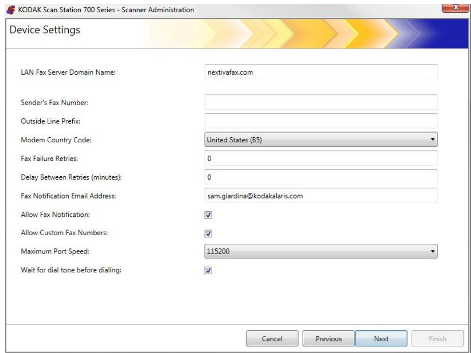
- If your phone system requires a number to get an outside line, enter the prefix that the user needs to enter, to access an outside line (e.g., 9 is frequently used and a comma “,” may be used to insert a pause) in the Outside Line Prefix field. Each comma pauses the dialing sequence for about 3 seconds. You can use multiple commas to increase the pause time, for example “9,,.”
- Select Modem Country Code to display a list of countries and the associated codes that configure the modem for use in the selected country.
- Enter the number of times the Scan Station will attempt to send a fax in the Fax Failure Retries field.
- Enter the number of minutes the Scan Station will wait between attempting to send a fax in the Delay Between Retries field.
- If you want someone to be notified every time a fax is sent (Success or Failure), enter the email address of the person/group who should be notified in the Fax Notification Email Address field.
- Check Allow Fax Notification if you want the user to be able to specify an email address, printer or both for Success and Failure notifications. Refer to the following table for how the Fax Notification Email Address and Allow Fax Notification work together.
| Fax NotificationEmail Addressfield | Allow Fax NotificationChecked | Allow Fax NotificationUnchecked |
| If specified | • Notification will be sent to the email address specified in the Fax NotificationEmailAddress field.• The user will also be able to enter an email address on the Scan Station before scanning; if an email address is entered, a notification will be sent to the address as well. | • Notification will be sent to the email address specified in the Fax NotificationEmailAddress field. |
| If left blank | • The user will be able to enter an email address on the Scan Station before scanning; if an email address is entered, a notification will be sent to the address. | • No notifications will besent. |
NOTE: Fax/Printer notifications can only be configured after destinations have been defined and at least one printer has been defined. For information about setting up a printer see the section entitled, “Setting up a printer destination” in Chapter 7.
- Check Allow Custom Fax Numbers if you want the user to be able to enter a fax number on the Scan Station.
- Select the Maximum Port Speed supported by your fax connection.
- Check Wait for Dial tone before dialing if required.
- When you have finished entering information on this screen, click Next. The following screen will be displayed. If you do not want to allow the Scan Station to receive taxes, click No.
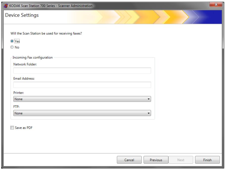
Receiving faxes at the Scan Station 730EX
- If you want your Scan Station 730EX to receive faxes1, click Yes in the screen above, and then select Next. You will be able to enter settings for incoming faxes.
-
Enter the required information in the Incoming Fax Configuration fields. Enter one or more of the following destinations:
-
a fully qualified path name to the Network folder where the incoming fax will be saved.
- the Email address of the person/group where the incoming fax will be delivered.
- the Printer name where the incoming fax will be sent for printing.
- the FTP site where the incoming fax will be saved.
NOTES:
- If you configure the Scan Station to receive incoming faxes, you must define at least one of the above destinations; otherwise the faxes will not be delivered.
-
In order for faxes to be routed to a printer, network folder or FTP site, these destinations must be created in advance before they may be selected.
-
Check Save as PDF if the incoming fax will be saved as a PDF file.
-
Click Finish.
Scan Settings provide basic image processing settings, such as, color/ grayscale/black and white, output file format, compression, and some advanced options like Hole Fill, Streak Filter, etc.
To define scan settings
1. Select Edit>Scan Settings.
The Setup Scan Settings screen will be displayed.
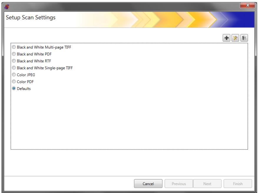
- Click the Add icon. The following screen will be displayed.
- Make selections from any of the categories (e.g., Black and White Settings, Advanced Settings, etc.).
NOTE: For a detailed description about the options, see the sections that follow.
- When finished making selections, click Next.
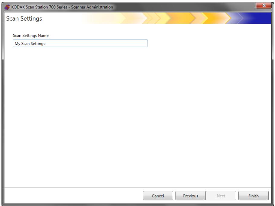
- Enter a name in the Scan Settings Name field that describes this scan setting.
- Click Finish.
- Click Finish.
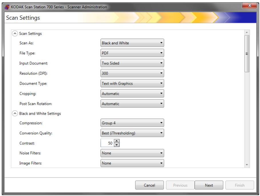
Scan Settings
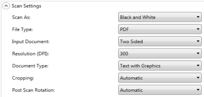
Scan As — select how you want documents to be scanned. Selections are: Color, Grayscale, Black and White.
File Type — select one of the following options:
- JPEG: this option is only available for Color or Grayscale. If your Scan As selection is Black and White and JPEG is selected, your Scan As selection will automatically change to Color.
- TIFF - Single Page: creates multiple files, one for each side of a scanned page.
- TIFF - Multi Page: creates one file that contains all of the scanned pages.
NOTE: The compression setting depends on the Scan As selection. If the Scan As selection is Black and White, select a compression setting from the Black and White Settings. If the Scan As selection is Color or Grayscale, select a compression setting from the Color Settings.
- PDF: creates a PDF document. See "PDF Settings" on page 61 for more information.
- DOC: creates a Microsoft Word document.
- RTF: creates a Rich Text Format file which can be read by a number of applications.
XLS: creates a Microsoft Excel spreadsheet.
NOTES:
- When scanning to DOC, RTF and XLS, optical character recognition is performed on the scanned image. The .doc, .rtf or .xls file produced is based on the OCR results; therefore, the result may not be identical to the original.
- When you select DOC, RTF or XLS, the Language option will be displayed. Select the language you want used to generate the file.
Input Type — select one of the following options:
- Two Sided: the Scan Station will scan the front and back in a single pass.
- One-Sided - Face Down: if you select this option, the documents must be put in the input tray face down (the side you want to scan facing the input tray).
- One-Sided - Face Up: if you select this option, the documents must be put in the input tray face up (the side you want to scan facing toward you).
Resolution (DPI) — select 100, 150, 200, 240, 300, 400 or 600 dpi. Higher resolutions produce better quality images, but larger file sizes.
NOTE: If the Document Type is PDF, this resolution setting is ignored because the PDF resolution setting is used.
Document Type — select one of the following options:
- Text with Graphics: the documents contain a mix of text, business graphics (bar graphs, pie charts, etc.) and line art.
Text: the documents contain mostly text. - Photographs: the documents contain mostly photographs.
Cropping — select one of the following options:
- Automatic: automatically detects the border of an image and straightens it if necessary.
- Aggressive: automatically detects the border of an image, straightens it if necessary, and eliminates any residual black border on any image edges. In order to achieve this, there is a possibility that a small amount of image data from the edge of the document may be lost.
Post Scan Rotation — select None or Automatic. If you select Automatic, the Scan Station will analyze each document to determine how it was fed and rotate the image to the proper orientation.
Black and White Settings
The Black and White settings will be grayed out, if your Scan As selection is Color or Grayscale.

Black and White Settings
Compression:
Conversion Quality:
Contrast:
Noise Filters:
Image Filters:
Group 4
Best (iThresholding)
None
None
Compression — you can select None or Group 4.
Conversion Quality -allows you to select Best (iThresholding) or Normal (ATP).
- Best (iThresholding) — the Scan Station dynamically evaluates each document to determine the optimal threshold value to produce the highest quality image. This allows scanning of mixed document sets with varying quality (such as faint text, shaded backgrounds, or color backgrounds) to be scanned using a single setting thus reducing the need for document sorting. When Best is selected, only Contrast can be adjusted.
- Normal (ATP) (Adaptive Threshold Processing) — separates the foreground information in an image (e.g., text, graphics, lines, etc.) from the background information (i.e., white or non-white paper background). When Normal is selected, you can adjust both Threshold and Contrast.
Contrast — adjusts the amount of the image foreground which is kept or attenuated. Decreasing this setting will reduce the amount of noise at the expense of possibly losing faint text. Increasing this setting will help make faint text more visible at the expense of creating more noise.
Threshold — aids in controlling the level at which a pixel is considered black or white. Decreasing this setting will make the image appear lighter, and can be used to subdue background noise. Increasing this setting will make the image appear darker, and can be used to help pick up light information. This options range from 0 to 255.
Noise Filters — select one of the following options:
- Lone Pixel: reduces random noise by converting a single black pixel to white when it is completely surrounded by white pixels or by converting a single white pixel to black when it is completely surrounded by black pixels.
- Majority Rule: sets each pixel based on its surrounding pixels. The pixel will become white if the majority of the surrounding pixels are white and vice versa.
Image Filters — you can select None or Halftone Removal. Halftone Removal enhances dot matrix text and images with halftone screens (e.g., newspaper photographs).
Color Settings

Color Settings
Compression:
Quality:
Brightness and Contrast:
Color Balance:
Sharpen:
Background Smoothing:
JPEG
Good
Automatic
Automatic
None
None
Compression — select JPEG, None or LZW. JPEG creates multiple files, one for the front and back of a page. If JPEG is selected, you can select a Quality option of: Draft, Good, Better, Best or Superior.
NOTE: LZW is only available if TIFF: Single Page or TIFF Multi Page is selected for the File Type.
Quality — allows you to select a Draft, Good, Better, Best or Superior quality option. When saving a file as PDF, predefined resolution settings will be used when selecting Good (150 dpi), Better (200 dpi), and Best (300 dpi). The Scan Station dpi settings will not be used when scanning in PDF mode.
NOTE: The quality settings impact the final size of the file (Draft producing the smallest file size and Superior producing the largest file size).
Brightness and Contrast — you can select None, Automatic or Manual. If you select Automatic, the Scan Station will select the values to use. If you select Manual, you can set specific values that will be used for all images:
- Brightness: changes the amount of white in the color or grayscale image. The values range from 1 to 100.
- Contrast: enhances or diminishes the differences between light and dark pixels.
NOTE: If you are scanning documents with faint text added for security and dark text that you want to keep for OCR, decrease this setting.
Color Balance — select one of the following options:
None
-
Automatic: adjusts the white background of each document to pure white. This option compensates for the variations that occur between different weights and brands of paper. This is not recommended for use with photographs.
-
Automatic - Advanced: for advanced users that want to further adjust the Automatic option.
-
Aggressiveness: allows you to adjust the extent of the variation. Increasing this value can help with documents that have yellowed due to age. The values range from -2 to 2.
-
Manual: allows you to set specific values that will be used for all images:
-
Red: changes the amount of red in the color image. The values range from 1 to 100.
-
Green: changes the amount of green in the color image. The values range from 1 to 100.
-
Blue: changes the amount of blue in the color image. The values range from 1 to 100.
NOTE: Color Balance is not available for grayscale images.
Sharpen — controls the enhancement of edges in the document. Options include: None, Normal, High and Exaggerated.
Background Smoothing — using this option for documents or forms with a background color will help produce images with a more uniform background color. This option improves image quality and may reduce file size.
- None
Automatic: smooths up to three background colors.
-
Automatic - Advanced: for advanced users that want to further adjust the Automatic option.
-
Aggressiveness: allows you to adjust the extent to which the background(s) are determined. The values range from -10 to 10.

Advanced Settings
Hole Fill:
Blank Image Detection:
Image Edge Fill:
Streak Filter:
Color Dropout:
Combine Front and Back Images:
Auto Color Detection:
Multifeed Ultrasonic Detection:
Maximum Document Length (in):
Reverse Page Order:

None
None

None
None
None

14

Hole Fill: allows you to fill in the holes that are around the edges of your document. The types of holes that are filled include: round, rectangular, and irregularly shaped (e.g., double-punched or those having a slight tear that could have occurred when the document was removed from a binder).
Blank Image Detection: used to detect blank pages (e.g., the back side of a document), so these pages can be discarded. If you select this option, you can select Based on Document Content where you can select an aggressiveness value where document images that fall below the value will be discarded.
Image Edge Fill: fills the edges of the final electronic image by covering the area with the selected color.
- None
- Automatic: the scanner will automatically fill the edges of the image using the surrounding color.
- Automatic - include tears: in addition to filling the edges, the Scan Station will also fill in tears along the edge of document.
- White: allows you to enter values for the Top, Bottom, Left and Right margins.
- Black: allows you to enter values for the Top, Bottom, Left and Right margins.
Streak Filter: allows you to configure the Scan Station to filter vertical streaks from your images. Streaks are lines which may appear on an image and are not part of the original document. Streaks may be caused by contaminants on your documents (e.g., dirt, dust or frayed edges) or by not following the recommended cleaning procedures for your Scan Station. Click Streak Filter to turn this option on where you can select an Aggressiveness value which allows you to adjust the extent at which the streaks are filtered. The values range from -2 to 2.
Color Dropout — used to eliminate a form's background so that only the entered data is included in the electronic image (e.g., remove the form's lines and boxes). For black and white images, these settings affect the grayscale version of the document which the Scan Station analyzes to produce that electronic image. This option is only applicable for grayscale and black and white images. Select one of the following options:
- None
- Multiple: drops colors other than dark shades (e.g., black or dark blue ink)
- Predominant: drops the predominant color
- Blue
Green
Red
NOTE: When you select Multiple or Predominant, you can adjust the Aggressiveness value to the extent at which colors are dropped. The values range from -2 to 2. The default is 0.
Combine Front and Back Images — typically one image is created for a document the front side and another image is created for the back side. Turn this option on if you want one image that contains both the front side and back side of the document. Select one of the following options:
None
- Front on Top: front side will be above the back side within the image.
- Front on Bottom: back side will be above the front side within the image.
- Front on Left: front side will be to the left of the back side within the image.
- Front on Right: back side will be to the left of the front side within the image.
Auto Color Detection — the scanner can detect color pages and automatically save a color (or grayscale) image instead of black and white, for just the color pages.
-
Low: image/page requires only a small amount of color to be saved as color/grayscale, e.g. primarily black text with small logos.
-
Medium: image/page requires more color, as compared with the Low option, before being saved as color/grayscale.
-
High: image/page requires more color, as compared with the Medium option, before being saved as color/grayscale. Used for distinguishing images containing medium- to large-size colorful photos from plain black text. Photos with neutral colors may require adjustments to the Color Threshold or Color Amount values in order to be captured correctly.
-
Custom: allows you to manually adjust the Color amount and/or Color threshold.
Color amount — the amount of color that needs to be present in a page before it will be saved as either color/grayscale. As the value of Color Amount increases, more color pixels are required. Valid values are 1 to 200.
Color threshold — the color threshold or saturation (i.e., pale blue vs. dark blue) at which a given color will be included in the color amount calculation. A higher value indicates that a more intense color is required. Valid values are 0 to 100.
NOTE: When setting Auto Color Detection values, it is suggested that you start with the Medium option and scan a typical job set. If too many images were returned as color/grayscale vs. black and white, then change to the High option and re-run the job. If too few images were returned as color/grayscale vs. black and white, then change to the Low option and re-run the job. If none of these options provide the desired result, select Custom to manually adjust Color Amount and/or Color Threshold.
Multifeed Ultrasonic Detection — multifeed detection aids in document processing by detecting documents that may go through the feeder overlapped. Multifeeds can happen due to stapled documents, adhesives on documents, or electrostatically charged documents. Check this option if you want to enable a Multifeed Response when a multifeed is detected.
-
Multifeed Sensitivity — controls how aggressively the scanner will work to determine if more than one document is fed into the scanner. Multifeeds are triggered by detecting air gaps between documents. This allows multifeed detection to be used with job sets containing documents with mixed thicknesses.
-
Low: least aggressive setting and is less likely to detect labels, poor quality, thick or wrinkled documents as multi-fed documents.
- Medium: use if your job set has varying document thicknesses or labels attached to the document. Depending on the label material, most documents with labels should not be detected as a multi-fed document.
- High: the most aggressive setting. This is a good setting to use if all documents have a thickness no greater than 20-lb. bond paper.
NOTE: Regardless of the setting, "sticky" notes may still be detected as multi-fed documents.
- Multifeed Response — select what action you want the Scan Station to take when a multifeed is detected. With all options, the condition will be logged in the Scan Station.
- Continue Scanning: the Scan Station will continue to scan.
- Stop Scanning: scanning will stop and you will have to option to continue scanning or cancel the batch. Verify that the paper path has been cleared and restart the scan session from the scanning application.
Maximum Document Length (in.) — allows you to select the maximum length of the documents in your job. If the Scan Station detects a document longer than this value, it will determine that a paper jam has occurred. The default is 14 inches. Maximum length is 160 inches; minimum length is 2.5 inches.
Reverse Page Order — if enabled, the Scan Station will reverse the order of the scanned images from the order in which the documents were scanned.
Allow Adding Pages To Scan Job — when enabled, the user can continue to add pages to a scan job. After all pages in the input tray have been scanned, a message will be displayed asking if they want to add more pages. If the user selects Yes, the additional pages will be scanned and the message will be displayed again until the user selects No, or the 30-second timeout has occurred.
Allow Adding Pages To Scan Job:
Barcode Type:

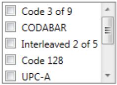
Barcodes are read anywhere on the front and back of a document. The read order is left to right, top to bottom in both horizontal and vertical orientations. A maximum of 10 barcodes are read on each side of a document.
NOTES:
- Barcode accuracy is highly dependent on the quality of the scanned image. Higher resolution and larger barcodes will increase accuracy. Recommended scanner settings are 300 dpi, black and white or grayscale. If your output type is PDF, the Best quality setting should be used. Image compression may also affect accuracy. Choose the minimum compression, or uncompressed, to increase read accuracy.
- If you define an Index Template, the values set in the index template will override any options selected here. See "Chapter 6 Index Templates" on page 65 for more information.
Select the barcode type(s) from the Barcode Type list that match the barcodes on the documents to be scanned. Barcode data read when a document is scanned will be saved as metadata to a corresponding .xml file. A .xsd file has been provided on the Installation CD to validate the metadata file for integration into your back-end system.
NOTE: You must check Enable output metadata in Device Settings to create the output metadata file.
Available barcode types are:
Code 3 of 9
- CODABAR
- Interleaved 2 of 5
Code 128
- UPC-A
- UPC-E
EAN8
EAN 13
- PDF-417
NOTE: Selection of multiple barcode types may affect throughput performance.
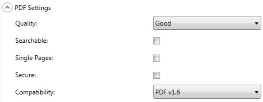
Quality — allows you to select a Good, Better or Best quality option. When saving a file as PDF, predefined resolution settings will be used when selecting Good (150 dpi), Better (200 dpi), and Best (300 dpi). The Scan Station dpi settings will not be used when scanning in PDF mode.
Searchable — creates a single- or multi-page document that contains both text and image data. OCR (Optical Character Recognition) technology is used to extract text information from the scanned image data. When you select this option, the Language option is displayed. Select the language you want used to generate the PDF file.
NOTE: This option specifically turns on OCR. OCR can also be enabled by selecting XLS, DOC and RTF output.
Single Pages — creates a PDF file for every page scanned. If scanning a two-sided document, a separate file will be created for both the front and back page.
Secure — allows the user to enter a password that will be used to encrypt the file before the file is delivered. The password will be sent in a separate email when Email is one of the destination selections.
Compatibility — this option is specialized for the digital preservation of electronic documents and is used if you want to generate a PDF that will be used for long term needs. Select the desired PDF option from the drop-down list.
NOTE: PDF/A and Secure are mutually exclusive.
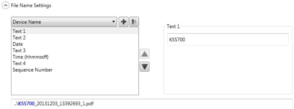
File Name Settings allow you to define values that determine the locations (directories or subdirectories) and file name used when creating scanned documents. You might want to:
- Define a folder name where scanned documents will be placed when scanning to a network folder, FTP location or USB drive destination.
- Define a file name prefix that will be applied to every scanned document created. Scanned documents are created with this prefix.
- Allow user input of other text to include in the file name, based on the specific documents being scanned.
- Include a date and time stamp in the file name.
For example, if you define a prefix of receipts with a date and time stamp, and a folder name of 2012, the scanned document file name will have the format: receipts_20120117_092219.tif and is placed in a folder called 2012.
- Device Name — allows you to use the Scan Station name in the file name or as part of the file path.
- User Name — the user name of the person logged into the Scan Station. If Force User login is disabled (not required to login to the Scan Station), the User name will be blank.
- Job Name — the title that is displayed on the Job button selected when using the Jobs screen. If working with the walk-up Scan Station, the Job name will be blank. This is not a valid selection if you have not defined a job. For more information see "Chapter 9 Create Jobs" on page 109.
- Date — allows you to enter the date in the file name or as part of the file path.
- Time (hhmmssff) — allows you to add the time (hhmmssff) in the file name or as part of the file path.
- Sequence Number — allows you to use a sequence number in the file name or as part of the file path.
-
Text — allows you to type in text that will be used in the file name or as part of the file path. This is limited to the maximum characters allowed by the target operating system.
-
User Input — causes the Scan Station to prompt for file name input when a user scans with this job; the value entered by the user becomes part of the file name.
- Directory Separator — allows you to use a separator in the file name or as part of the file path.
NOTES:
- Use the up and down arrows to reorder the items in the boxes.
- When entering values, the sample file name will be displayed in the text box at the bottom of the screen.
- When you select Text, Date or Sequence Number additional selections will be displayed on the right.
- At least one entry must always be in the File Name field.
- If you defined an Index Template, the values set in the index template will override any options selected here. For more information, see "Chapter 6 Index Templates" on page 65.
This chapter provides procedures for using the Index Template to define barcode and OCR regions and then use them to create a path and file name.
An index template is used to define index fields on a document to be scanned. The index fields contain information that can be used to classify, sort, or store the scanned documents in a particular order (referred to as indexing). The index fields will either be one or more barcodes and/or one or more areas of text (OCR data). The index template also allows you to specify how to use the index field from a defined region in a file name or directory path.
An index template allows you to specify where the barcode and OCR is on the document and where to use the information when creating the path and file name for the scanned document.
Index templates are used in conjunction with Jobs (see "Chapter 9 Create Jobs" on page 109 for more information). A Job will be set up to process each type of form along with any documents related to that form. For example, one job may be setup to process an insurance form, another job may be setup to process an invoice form, etc. An index template would be defined for each unique type of document (form) and then associated with the job configured to scan and process that form.
Each index template is associated with one form.
Creating an index template
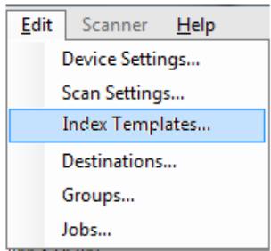
The steps below describe how to set up an index template. See the sections that follow for field and icon descriptions on each of the Index Template screens. There are two Index Template Settings screens: one screen is where you add, edit and delete index templates; the other screen is where you define the name of the index template.
- Scan a representative document for each type of unique document (form) that you want to define a barcode or OCR index.
-
Select Edit>Index Templates. The Setup Index Templates screen will be displayed. If index templates have already been defined, they will be listed on this screen, otherwise the screen will be blank.
-
Click the Add icon . The Index Template Settings screen will be displayed.
-
Select the Index Field Editor icon to create a barcode and/or OCR index fields The Index Field Editor screen will be displayed.
- Click the Open Image icon . The Select Image dialog box will be displayed.
- Select one of the scanned documents you scanned in Step 1 that you want to apply an barcode/OCR region to. When the image is selected, it will be displayed in the image window on the Index Field Editor screen.
-
Determine if you want to create a barcode or OCR region.
-
If you want to define a OCR region, click the OCR icon OCR.
- If you want to define a barcode region, click the Barcode icon
When the icon is clicked, a cross hair is displayed. Move the cross hair to the area you want to select, click and hold the left mouse button, drag the cross hair across the part of the image you want and release the button. Depending on your selection the Barcode (or OCR) Field Properties screen will be displayed.
NOTES:
- If you want to change the location of the index field, click inside the field and drag it to a new location.
- If you need to change the size of an index field, click one of the red handles and drag it to adjust the size.
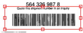
-
If an index field is selected, the Barcode and OCR icons will be disabled. Click anywhere outside of an index field to enable these icons.
-
Define the barcode or OCR region on the Barcode Field Properties screen or the OCR Field Properties screen and click Done. The Index Field Editor screen will be redisplayed with the index(es) and index field properties you set up. Click OK. The Index Template Settings screen will be displayed.
-
Define your File Name Settings by selecting the values from the drop-down list and click Next.
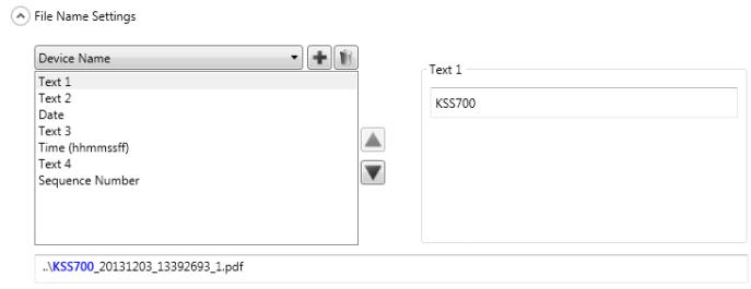
- When the Index Template Setting screen is displayed, enter the desired template name in the Index Template Name field and click Finish to return to the Setup Index Templates screen. The index template you created will be displayed.
Setup Index Templates screen
The Setup Index Templates screen displays any index templates that have been previously defined and allows you to add, edit and delete index templates.
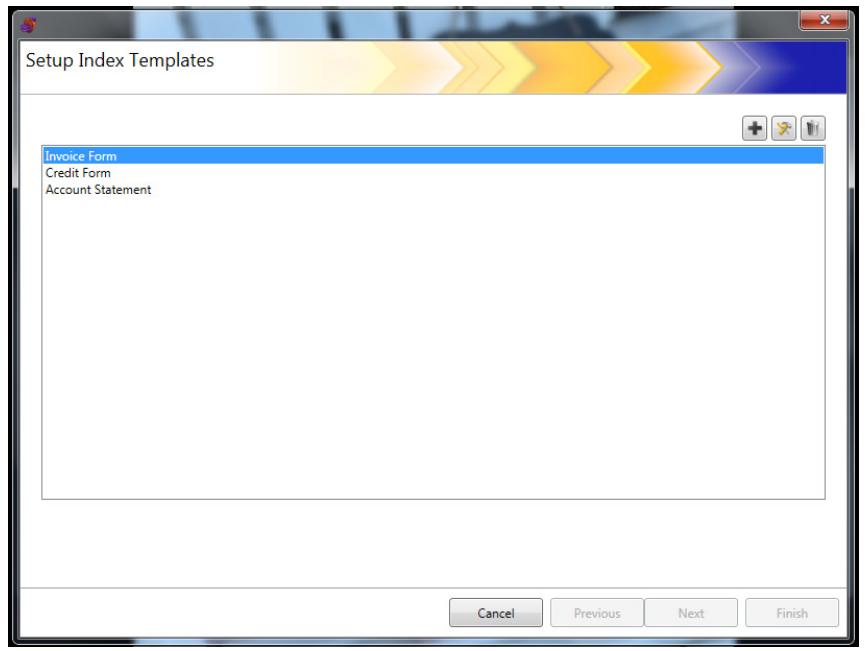
| Icon | Description |
| + | Displays the Index Template Settings screen, which allows you to add an index template. |
| × | Allows you to view or edit the selected index template. |
| Allows you to delete the selected index template. |
Index Template list — displays the index templates that have been created.
Cancel — closes the Setup Index Templates screen and returns you to the Kodak Scan Station 700 Series - Scanner Administration main screen.
Previous, Next, Finish — not available on this screen.
Index Template Settings screen
The Index Template Settings screen allows you to create and maintain index fields.
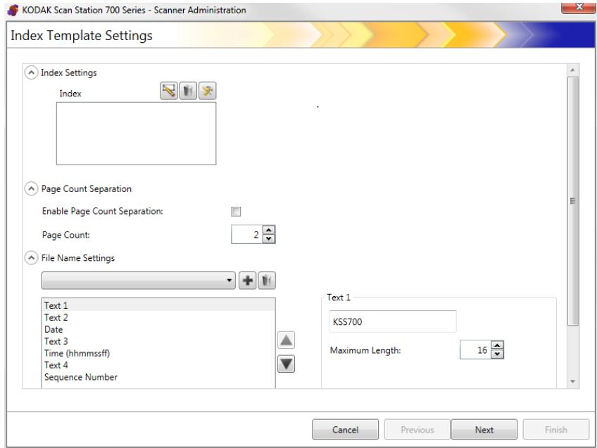
Index Settings
| Icon | Description |
| Index Field Editor icon displays the Index Field Editor screen where you can create a barcode or OCR index field(s) for your index template. | |
| Allows you to delete the selected index field. | |
| Allows you to view or edit the selected index field. |
- Index box — displays the index fields that have been created for your index template.
- Page Count Separation — allows you to separate documents based on number of pages. If page count separation is enabled then separation based on a barcode cannot be enabled.
File Name Settings
| Icon | Description |
| + | Allows you to add the file name value that is currently displayed or selected in the File Name Settings drop-down list to your file name path. Any indexes that you have defined will also be displayed in the list. |
| Allows you to delete the selected index field. |
File Name Settings field — allows you to define values that determine the locations (directories or subdirectories) and file name used when creating scanned documents. You can define a folder name where scanned documents will be placed when scanning to a network folder, FTP location or USB drive destination. Click the down arrow to display a list of values that you can add to your file name path. You must make at least one entry in this field.
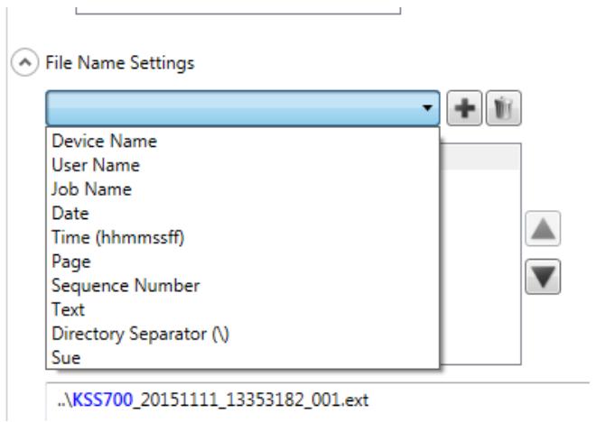
- Device Name — uses the Scan Station name in the file name or part of the file path.
- User Name — uses the logged-in user name in the file name or part of the file path.
- Job Name — uses the job name in the file name or part of the file path.
- Date — allows you to enter the date in the file name or part of the file path.
- Time (hhmmssff) — adds the time (hhmmssff) in the file name or part of the file path.
- Page — uses a page number in the file name or part of the file path.
-
Sequence Number — uses a sequence number in the file name or part of the file path.
-
Text — allows you to enter any text that will be used in the file name or as part of the file path. This is limited to the maximum characters allowed by the target operating system.
- User Input — causes the Scan Station to prompt for file name input when a user scans with this job; the value entered by the user becomes part of the file name.
- Directory Separator — uses a separator as part of the file path.
- Indexes — these are the names that you defined when you configured your barcode and/or OCR regions which you can use in the file name or as part of the file path.
NOTES:
- Use the up and down arrows to reorder the items in the boxes.
- When entering values, the sample file name will be displayed in the text box at the bottom of the screen.
- When you select Text, Date or Sequence Number additional selections will be displayed on the right.
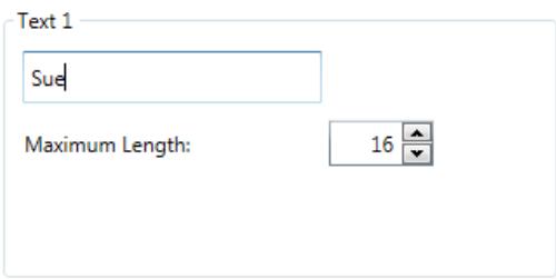
- At runtime, invalid file name characters will be replaced by a "?"
- At runtime, file names cannot exceed 256 characters in length.
Cancel — closes the Index Template Settings screen and returns you to the Setup Index Templates screen.
Next — goes to the next Index Template Settings screen where you can enter a name for this index template.
Finish — saves your selections and returns to the Setup Index Templates screen.
NOTE: If you are setting up a new index template, Finish will not be available, you must click Next to name your index template.
Index Template Settings (name) screen
The Index Template Settings (name) screen will be redisplayed after you configure your index template values where you will enter an Index Template name.
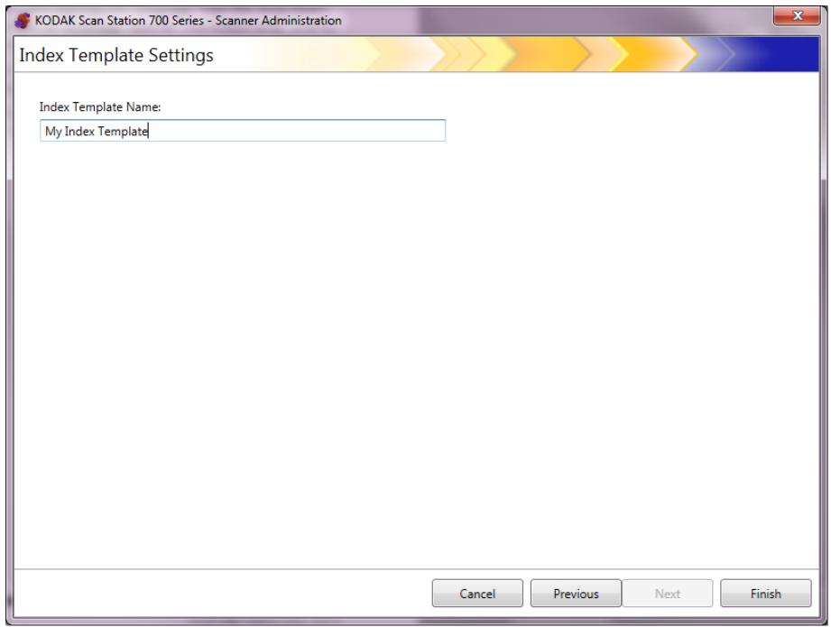
Cancel and Finish — returns to the Index Setup Template screen.
Previous — returns to the previous screen.
Index Field Editors screen
Use this screen to create barcode and/or OCR index fields.
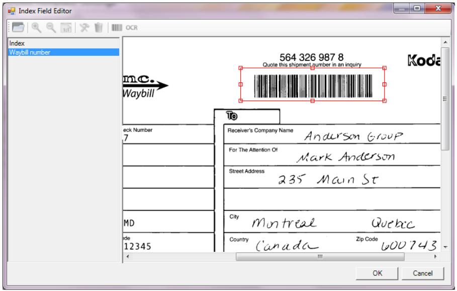
Icons

Open Image: displays the Select Image dialog box where you can select a JPEG or TIFF image to apply an OCR and/or barcode region to.
View icons: select the Zoom In, Zoom Out or Actual 1:1 icon to view the image at the desired viewing size.

Edit: displays the OCR Field Properties or Barcode Field Properties screen where you can make changes to the selected index value.

Delete: deletes the selected index value.

Barcode: displays the Barcode Field Properties screen where you can set up the properties of a barcode index field.

Index: displays the OCR Field Properties screen where you can setup the properties of an OCR index field.
Index box — displays any index fields that you have defined for this index template.
Viewer area — when an image is selected, it will be displayed in the Viewer area of the Index Field Editor screen where you can select an area to apply an OCR and/or barcode region to.
Properties box — displays the options that you selected on the Barcode Field Properties and/or OCR Field Properties screen.
OK — saves your changes and returns to the Index Template Settings screen.
Cancel — closes the Index Field Editor screen without saving any changes.
Barcode Field Properties screen
The Barcode Field Properties screen allows you to set up a barcode index field and this screen can be accessed by releasing the mouse button after drawing the region around the desire barcode field or by selecting the Edit icon on the Index Field Editor screen.
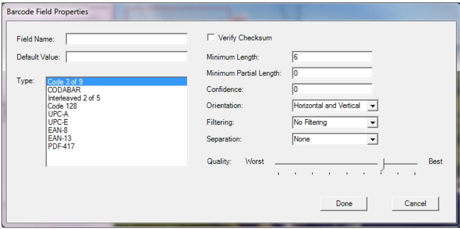
- Field Name — the barcode field must have a name in order to save it. This name identifies the barcode field and is displayed in:
- the Index list in the Index Field Editor.
- the Index list in the Index Template Settings screen.
- the File Name Settings drop-down list.
- Default Value — the value entered in this field will be used if the barcode cannot be read or is missing.
- Type — lists the types of barcodes that are available. Only one barcode type can be selected. The following barcode types are supported:
| Code 3 of 9 | UPC-E |
| CODABAR | EAN-8 |
| Interleaved 2 of 5 | EAN-13 |
| Code 128 | PDF-417 |
| UPC-A |
- Verify Checksum — check this box if the barcode contains a checksum character. Checksum characters help ensure the accuracy of barcode reading. Not all barcode types support checksum verification. Barcode types that optionally support checksum verification include: Code 3 of 9, CODABAR and Interleaved 2 of 5.
Some barcode types such as, PDF-417, UPC and EAN have a built-in checksum capability that cannot be disabled.
If Verify Checksum is not checked for barcodes containing a checksum, the checksum value (usually the last character of the barcode) will appear in the barcode value; otherwise, the check digit will remain hidden.
If checksum verification fails during scanning, a barcode value is not generated. Some barcode types, such as Code 128, have mandatory checksum characters. The code is always present and must be correct for the value to be read. Other codes have optional checksum characters which then add an additional character when present.
To read invalid Code 128 symbols, you can select the Minimum Partial Length option. It will report the data characters even if checksum fails. The invalid checksum will not be returned. When the barcode has an optional checksum, it will not be validated by the software.
Selecting Minimum Partial Length for a barcode with an optional checksum will return what it finds, whether it is good or bad. Occasionally, a barcode will return the correct result but the checksum fails.
- Minimum Length — enter a minimum length of the barcode value in this field. The default minimum length is 6. It is recommended that the minimum length be set at 6 or less in order to retain barcode values in cases of a partial reading.
- Minimum Partial Length — enter a value in this field if you want to generate a barcode value, even if it is incomplete. This is useful for barcodes that are only used for document separation where the absolute value is less critical.
NOTE: Minimum Partial Length should not be used when Verify Checksum is checked, as this may result in a barcode value being generated when checksum verification fails.
- Confidence — enter a number in this field to restrict what is considered to be a successful barcode read. For example, the higher the value that is entered, the chance of misreading barcodes will be reduced. Confidence values range from 0 (any confidence) to 100 (absolute certainty).
- Orientation — specify the orientation of the barcodes in the document. Selections are: Horizontal, Vertical and Horizontal and Horizontal.
-
Filtering — when reading barcodes from fax machines or other devices that may have CCD pixel dropout, applying a filter may help the read rate if bars are missing pixels. Selecting Filter1 will fill a gap in a bar of 1 pixel. Filter2 will fill a gap of 2 pixels, etc.
-
Separation — allows you to use a barcode as an indicator to create a new document. This document is referred to as a “separator document”. Separation can only be selected for one index.
- None
- Create a new document — the separator document and all following documents are separated into a new document.
- Delete Page — all documents following the separator document are separated into a new document. The separator document is deleted. This is important when the separator document is used for the purpose of document separation and does not contain any significant information. The barcode, however, is still available for indexing. However, if Delete Page is enabled, and Enable output metadata (Device Settings/Configuration Options) is also enabled, the bar code from this deleted page will not show up in the xml file.
- Delete duplex page — deletes the separator document and the following page when scanning two-sided documents. This is important when a separator document is used for the purpose of document separation and does not contain any significant information. The barcode, however, is still available for indexing. However, if Delete duplex page is enabled, and Enable output metadata (Device Settings/Configuration Options) is also enabled, the bar code from this deleted page will not show up in the xml file.
NOTE: Do not enable Blank Page Detection when using the Delete duplex page option.
- **Quality — If desired, select a quality setting between Worst and Best. The highest quality barcodes are printed by a laser printer or pre-printed with an offset printer. Lower quality barcodes are printed with inkjet or dot-matrix technology. Depending on the quality of barcodes being scanned, set the Quality level accordingly. The higher the quality setting, the faster the barcode read performance.
Done — saves your barcode index fields and returns to the Index Template Settings screen.
Cancel — closes the Barcode Field Properties screen and returns you to the Index Template Settings screen without saving your changes.
OCR Field Properties screen
The OCR Field Properties screen allows you to set up an OCR index field. This screen can be accessed by releasing the mouse button after drawing the region around the desire OCR field or by selecting the Edit icon on the Index Field Editor screen.
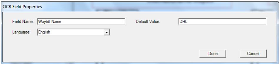
-
Field Name — enter the name of the OCR field. The OCR field must have a name in order to save it. This name identifies the OCR field and is displayed in:
-
the Index list in the Index Field Editor.
- the Index list in the Index Template Settings screen.
-
the File Name Settings drop-down list.
-
Default Value — the value entered in this field will be used if the OCR index field cannot be read or is missing.
- Language — select the appropriate language from the drop-down list to ensure that special language-specific characters (e.g., or ) will be recognized.
Done — saves your OCR index values and returns to the Index Template Settings screen.
Cancel — closes the OCR Field Properties screen and returns you to the Index Template Settings screen without saving your changes.
Use cases
Following are some use cases where barcode detection can be useful. There could be many variations on these cases but these should be helpful in understanding how Scan Station uses barcode detection.
Car dealership
A car dealership has 20 locations and a key part of its business depends on processing car loan applications. The customer is usually waiting in the lobby for the approval. A car loan application is done on a standard paper form which contains a unique barcode. Supporting documentation such as a copy of a driver's license, taxes, proof of income or residence can also be provided.
Problem
The salesperson fills out the application with the customer and faxes it to the corporate office. The salesperson calls the corporate office to be sure it arrived and is being processed. The image quality of the fax is frequently poor and rescans are common because settings are not preset. Therefore, the salesperson spends their time trying to keep the customer from leaving the dealership and calling the corporate office to determine a decision on the loan.
Solution
Using a Scan Station a Car Loan job is configured to have the correct scan settings and destination. The salesperson walks up to the Scan Station with the loan application and supporting documentation, scans the document(s) in the correct order and selects the preconfigured Car Loan button. The job is setup to scan a region of interest on the image for a barcode. The barcode is scanned and the value is used to uniquely name the file (Car Loan Number).
The output filename is formatted such as:
Dealership1-Salesperson1-CarLoanNumber.pdf
The destination is an email address at Corporate Finance.
The salesperson sees the job is scanned and has completed successfully. They turn their attention to the customer and a few minutes later a text message from Corporate Finance arrives indicating the loan application is being processed and should be completed within 30 minutes.
Shipping Company
Problem
A shipping company has hundreds of locations that accept packages for foreign shipment and needs to scan documents that accompany shipments for Customs. The scanned documents are sent to a central location which prepares bills of lading so when packages arrive, they can go directly on planes that will travel to foreign locations. In the past, the shipping company tried using multi-function printers (MFPs) but the interface was difficult to use, the image quality was poor and the MFP was not dedicated to this task.
The first page of each shipment request is a standard form the customer fills out and contains a unique barcode. Supporting Customs documentation is usually provided (letters of package description, ECCN, government mandated extras, etc.). When the form is filled out, a shipping company employee types in the destination address and contact information, then scans the barcode on the shipment request to associate it with the record they are creating. At this point, for example, the employee would know the package is going to Brazil.
The foreign shipment request and supporting documentation is scanned and the images are sent to the international desk. There, the paperwork will be processed to ensure it complies with foreign country customs and to create the bill of lading. The paperwork is sent with the physical package and will travel together to the destination country customs. On receipt of the package at the shipper's hub, the paperwork is checked against the bill of lading that was sent ahead of the package. The goal is to have no exception processing in 95% of the cases so the packages can ship overnight.
Solution
Using a Scan Station a Foreign Shipment job is configured with the correct scan settings and destination. The destination will be a secure FTP server at the corporate office. The document will be saved as a multipage TIFF file.
The path and filename will be used to identify the document, for example:
ftps:\corporate- server\ShippingCoLocation\ScanStationName\Date\ForeignShip-[barcode].tif
The shipping company also requires an accompanying XML file to be created with the same file name prefix as the multipage TIFF file. This file will contain the barcode value, the final destination, the shipper's name, address and account number, the number of pages in the document and the creation timestamp of the multipage TIFF. The final destination, shipper's name, address and account number derive from a database query using the barcode value as the search key.
On the server side, when the company sees the multipage TIFF and XML files in an SFTP directory, it knows that the copy operation is complete. The files are then copied to a different location, parsing the XML, comparing to the image document, logging the transaction and deleting the multipage TIFF and XML files from the SFTP directory.
Hotel Management Company
Problem
A company owns over 100 hotels in 70 countries around the world. The manager of each hotel can authorize discounts on the services they provide to their guests but must record the discount for operations, tax and governance reasons. For each discount an invoice for the hotel's services is altered (in handwriting) by the general manager and signed by a customer. The invoice is then scanned and sent to accounting at the corporate office while a record of the transaction is recorded in the local hotel's daily ledger. By law, all discounts must be justified back to corporate and all books aligned in 24 hours or less.
Solution
The invoice is usually a one-page document with a unique barcode. The discount is written by hand, the customer signs acknowledgement of receipt of the discount, the altered invoice is scanned and the image is sent to the corporate office.
A single page JPEG is sent to an SFTP destination where the directory name needs to vary at the time of the scan, based on the hotel location, machine name, the user who is scanning and barcode value of the invoice and date/time.
Example:
sftp:\corporate-server\discounts\country\hotel-location\machine-name\user\barcode value-date-time.jpg
In most cases, each invoice will be a single page. In 5% of the cases, the invoice may be two pages or more. In these cases, the file name should be the same as the first, but with a sequential suffix added.
Example:
sftp:\corporate-server\discounts\country\hotel-location\machine-name\user\barcode value-date-time.jpg
sftp:\corporate-server\discounts\country\hotel-location\machine-name\user\barcode value-date-time-01.jpg
When the next barcode is read the filename is reset to:
sftp:\corporate-server\discounts\country\hotel-location\machine-name\user\barcode value-date-time.jpg
This chapter provides procedures for adding destinations (e.g., email, network folder, printer, FTP, etc.).
Accessing the Destinations screen
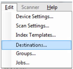
- Select Edit>Destinations. The Setup Destinations screen will be displayed.
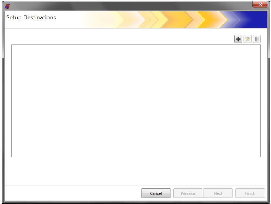
- Click the Add icon to display the Destinations screen. The Destinations screen allows you to create destinations for: Email, Network, Printer, FTP, Fax1, Email to Fax, SharePoint and Kofax Front Office Server.
NOTE: You cannot define a Fax and Email to Fax destination in the same configuration.
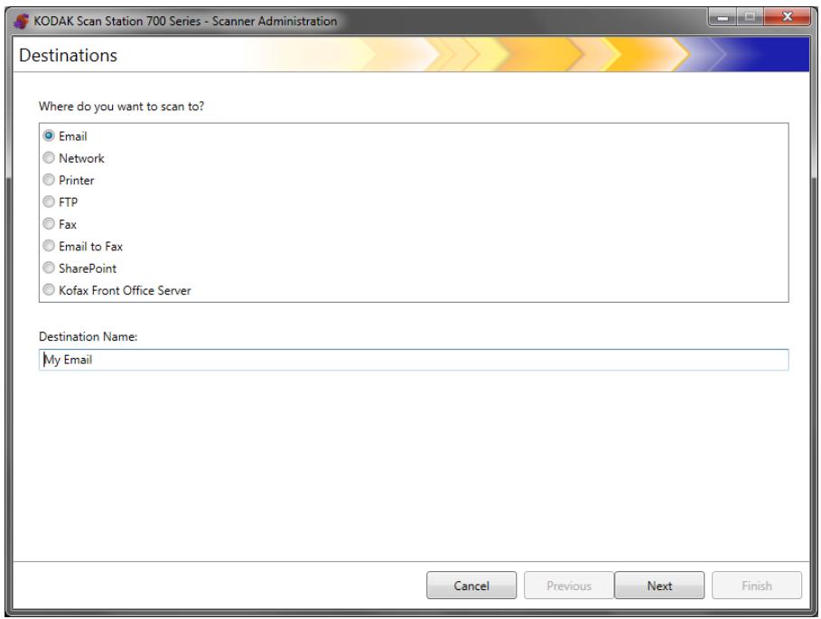
- Select the destination type you want to create. When you select a destination type, a recommended name for the destination will be displayed in the Destination Name field. You can change this name by entering a name that is meaningful to you. This is the name that will be displayed on the Scan Station touchscreen.
- Click Next. The application will step you through each destination configuration.
NOTE: For a detailed description about the different destination types see the sections that follow.
Destination layout and terminology
After setting up a destination, a screen similar to the one below will list your destination types, destination groups and destinations.
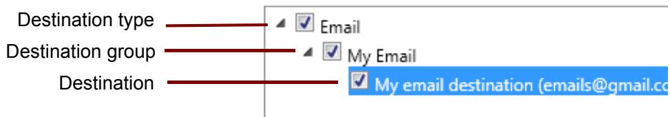
Setting up a email destination
- Select Edit>Destinations. The Setup Destinations screen will be displayed.
- Click the Add icon to display the Destinations screen.
- Select Email.
- Click Next.
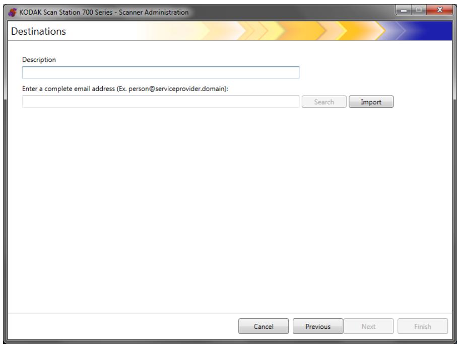
-
Enter a name in the Description field and an email address in the Enter a complete email address field where you want the scanned documents to be sent.
-
Search allows you to search the network address book for email addresses. Any addresses found while searching can be added to the currently selected email group.
NOTES:
- The network address book is the one associated with the SMTP server configured under Device Settings (Email server).
- If more than 20 addresses are found that match the search criteria, you may want to refine your search by adding more information, such as the first name of the person you are searching; for example, "smith joe" instead of just "smith".
- Wildcards can be added before and after the search criteria.
-
The Search function relies on the Active Directory Server device settings specified to function correctly. See "Configuring Active Directory Server settings" on page 41 for more information.
-
Import allows you to import a CSV file. See "Importing an email address book" on page 85 for more information.
-
Click Finish. The following screen will be displayed showing the email destinations and groups.
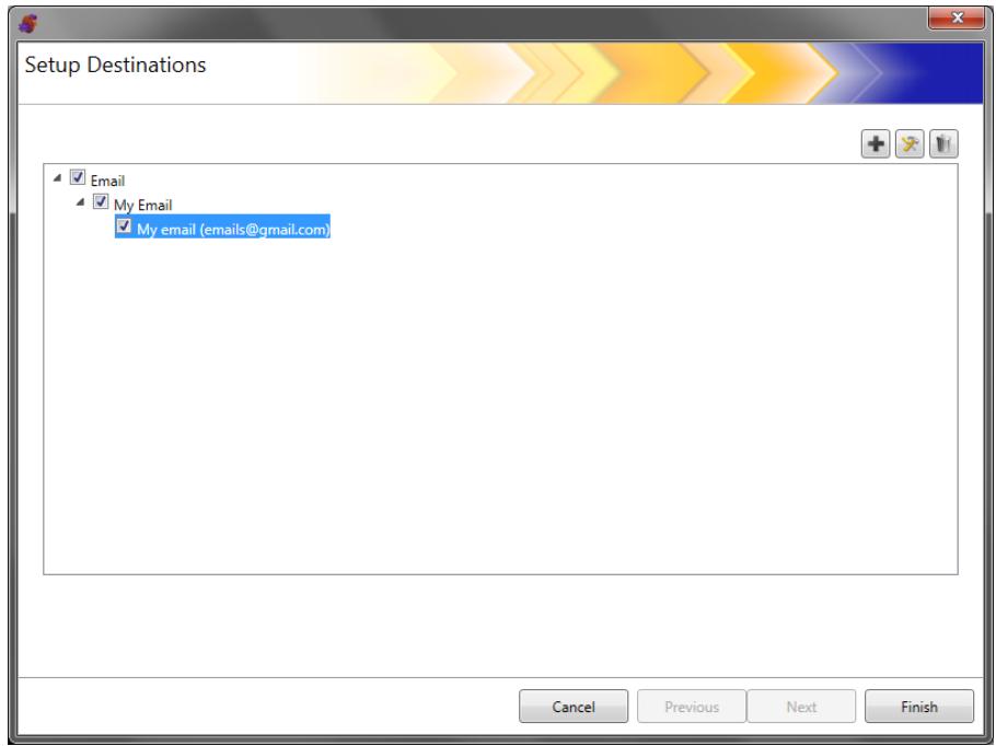
- If you want to add more email destinations within the same email destination group, click the Add icon and repeat Steps 5 and 6.
- To add another email destination group, select the email destination type and then click the Add icon, otherwise, click Finish.
Importing an email address book
CSV files are data files that represent database information. Each row contains data values that are separated by a comma. Each comma found on a line of text represents a column of data from the original database. The example below shows typical data exported from Microsoft's Outlook Express.
NOTE: The first row may contain the data column header information and not actual data.
First Row First Name,Last Name,Email Address Smith,John,johnsmith@rochester.rr.com Tom,Brown,Tombrown123@yahoo.com William,Doe,wdoe@msn.com
Outlook Express allows you to export your email address book to a comma-separated file. When you export your email address book, you can select which data columns you want to export.
NOTE: Other email programs may not allow you to select which data columns to export.
It is recommended that you only export the first name, last name, and email address.
- Click Import. The Import Email Addresses dialog box will be displayed.
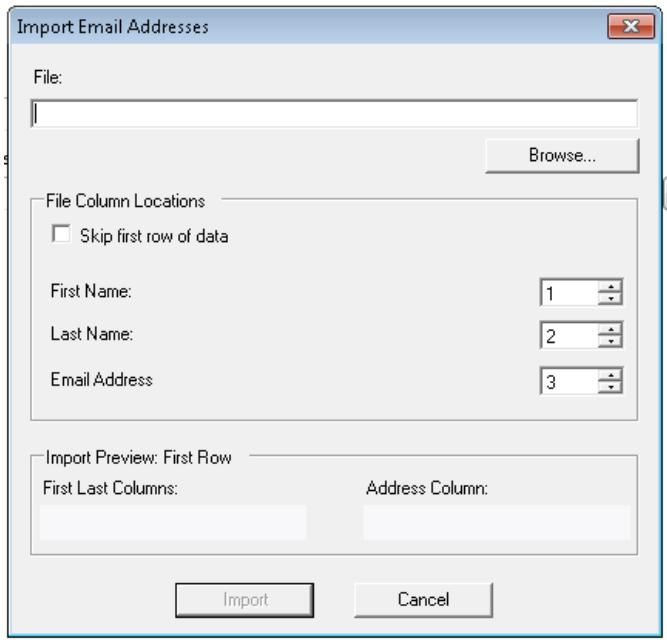
-
Enter the file name in the File field that contains the email addresses you want to import. If necessary, use the Browse button to locate the file.
-
Many email client applications automatically export the column headings as the first row of data. If you do not want to import the column headings as the first row, check Skip first row of data.
NOTE: Some email applications also export the data with additional quote characters surrounding the data. The quote characters will be removed while importing data.
- Enter the column numbers where the First Name, Last Name and Email Address appear in the CSV file.
After selecting a CSV file and column locations, a preview will be displayed showing the results of the file Column Location selections. If the column selections are changed, the preview will reflect these changes.
For example, if the three File Column Location values are 1, 2, and 3 the preview would display the following:
| First Name Last Name | Email Address |
The First Name and Last Name are combined to form the email address display name. The Email Address is used to create the email address.
If all three File Column Location values were set to 1, then the preview would look like this:
| First Name First Name | First Name |
- Click Import. The email addresses will be added to the selected email group.
Setting up a network destination
- Select Edit>Destinations. The Setup Destinations screen will be displayed.
- Click the Add icon to display the Destinations screen.
- Select Network.
- Click Next.
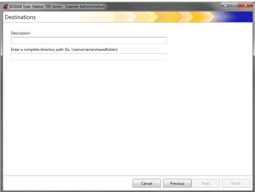
- Enter a network destination name that is meaningful to you in the Description field.
- Enter a fully qualified folder path in the Enter a complete directory path field and click Finish.
NOTE: You must use a full network path if you are scanning to a DFS based network.
The following screen will be displayed showing the network destination and group.
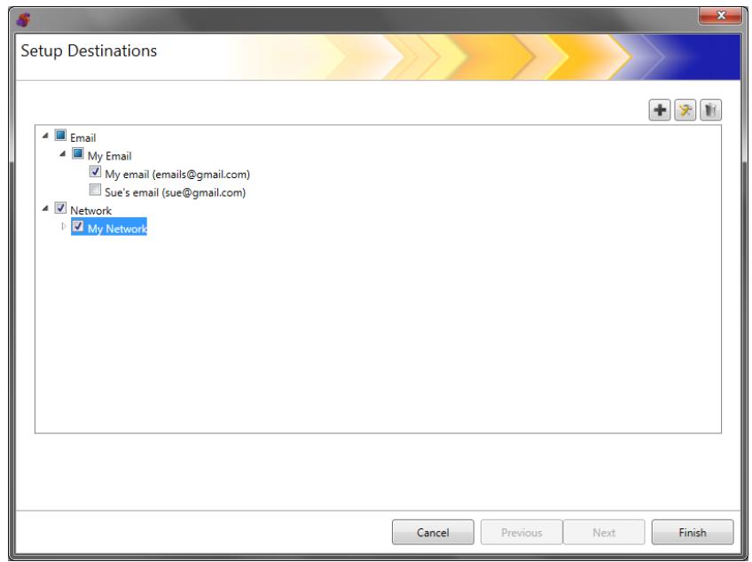
- If you want to add more network destinations within the same network destination group, click the Add icon and repeat Steps 5 and 6.
- To add another network destination group, select the network destination type and then click the Add icon, otherwise, click Finish.
Setting up a printer destination
Before installing printers, be sure you have a Windows 7, 32-bit compatible driver for the Scan Station 700/720EX or a or Windows 8, 64-bit compatible driver for the Scan Station 710/730EX.
The Scan Station can connect to printers in the following ways:
- Connect to a printer that is connected to a print server on a network domain. See "Setting up a print server printer destination" on page 89 for procedures.
- Connect to a printer that is shared by another computer on a network workgroup. See “Setting up a shared workgroup printer destination” on page 91.
- Connect to a network printer that is directly connected to the network via an Ethernet cable plugged directly into a router or hub. See "Setting up a printer connected directly to the network" on page 93.
In each of these scenarios, Microsoft Windows may also require login credentials for any device requesting access to a network printer.
Setting up a print server printer destination
If you want to connect to a printer through a print server on a network domain do the following.
- Select Edit>Destinations. The Setup Destinations screen will be displayed.
- Click the Add icon to display the Destinations screen.
- Select Printer.
- Click Next.

- Enter any text that describes the printer in the Description field.
- Enter the fully qualified path to the print server and print queue (e.g., \printservername\printqueue) in the Enter a complete directory path field.
- If the network domain is configured to require authentication to connect to the printer, enter theUsername, Password, and Domain names.
NOTES:
- If proper authentication is not provided, the printer and its driver may not be installed on the Scan Station.
-
Printer Driver Settings are not required for this configuration.
-
Click Finish. The following screen will be displayed showing the printer destination and group.
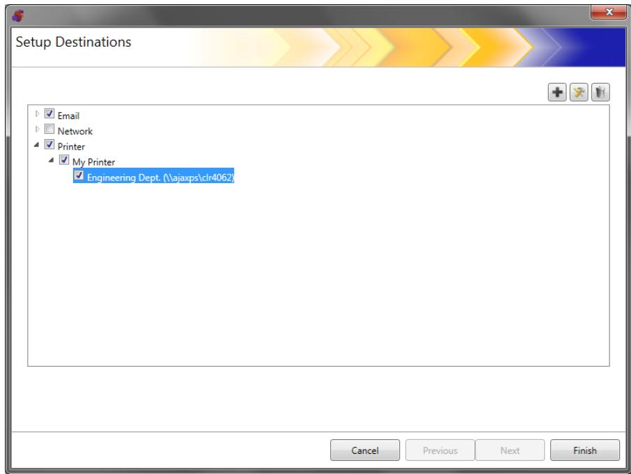
- If you want to add more printer destinations within the same printer destination group, click the Add icon.
- To add another printer destination group, select the printer destination type and then click the Add icon, otherwise click Finish.
Setting up a shared workgroup printer destination
If you want to configure a printer that is shared by another computer on the network, follow the steps below.
IMPORTANT: In order to complete this configuration you need to have knowledge on how your printers are set up in your organization. Any questions should be directed to your system administrator.
-
Select Edit>Destinations. The Setup Destinations screen will be displayed.
-
Click the Add icon to display the Destinations screen.
-
Select Printer.
-
Click Next.
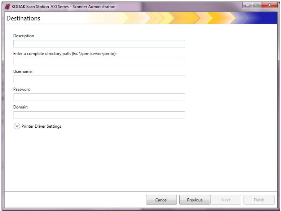
- Enter any text that describes the printer in the Description field.
- Enter the fully qualified path to the print server and print queue (e.g., \printservername\printqueue) in the Enter a complete directory path field.
- If the computer sharing the printer is configured to require authentication to connect to the printer, enter theUsername, Password and Domain.
NOTES:
- If proper authentication is not provided, the printer and its driver may not be installed on the Scan Station.
-
Printer Driver Settings are not required for this configuration.
-
Click Finish.The following screen will be displayed showing the printer destination and group.
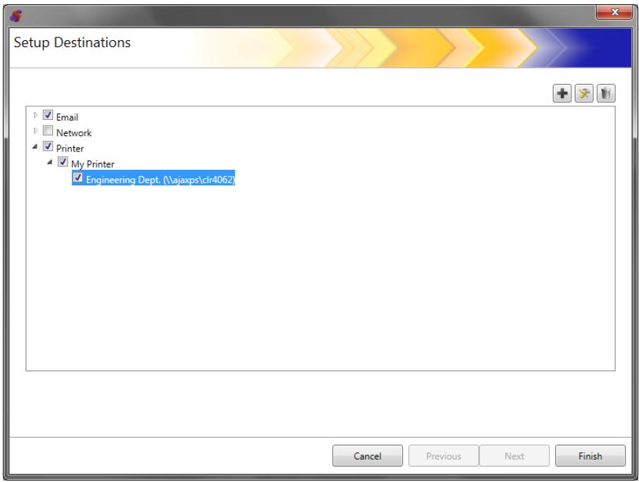
-
If you want to add more printer destinations within the same printer destination group, click the Add icon.
-
To add another printer destination group, select the printer destination type and then click the Add icon, otherwise click Finish.
Setting up a printer connected directly to the network
If you want to configure a printer that is connected directly to the network, follow the steps below.
-
Select Edit>Destinations. The Setup Destinations screen will be displayed.
-
Click the Add icon to display the Destinations screen.
-
Select Printer.
-
Click Next.
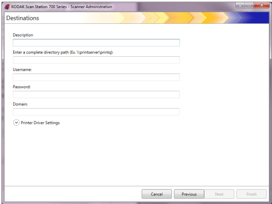
- Enter any text that describes the printer in the Description field.
- In the Enter a complete directory path field, enter the network printer IP address and print queue (e.g. \192.168.1.136\printQueueName).
-
If user credentials are required to access the location of the printer driver, enter them in theUsername, Password, and Domain fields.
-
In the Printer Driver Settings section, enter the location of the printer driver setup information file in the Printer Driver Location field or use the Browse button. The printer driver can be located on any PC connected to the same network and its location must be accessible from the Scan Station(s).
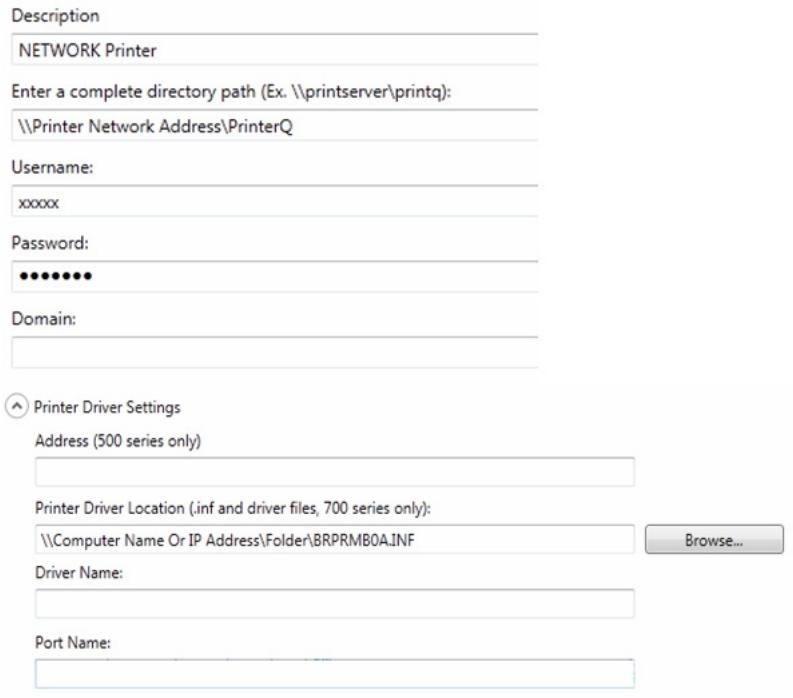
NOTE: If you are creating a configuration to be used on the older Scan Station models (500/520EX) enter the address of the print server containing the printer driver into the Address (500 series only) field.
- Print a test page on the target printer from another computer.
- Enter the driver name in the Driver Name field. This string can be found on the test page.
- Enter the port name into the Port Name field. This string can be found on the test page.
- Click Finish.
- If you want to add more printer destinations within the same printer destination group, click the Add icon.
- To add another printer destination group, select the printer destination type and then click the Add icon, otherwise click Finish.
The printer driver will be installed from the sharing PC. After the initial installation, the Scan Station will be able to communicate directly with the network printer.
NOTE: If a printer fails to install, check the logfile for the error code and search for the error code on the Microsoft website.
Setting up a FTP site
- Select Edit>Destinations. The Setup Destinations screen will be displayed.
- Click the Add icon to display the Destinations screen.
- Select FTP.
- Click Next.
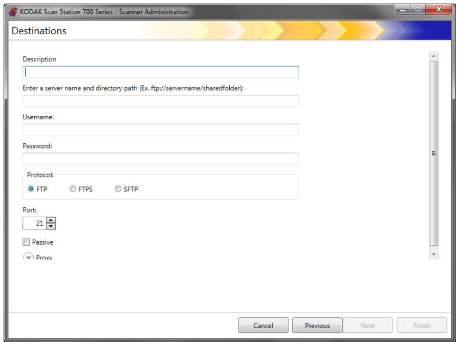
- Make an entry in the Description, Enter a server name and directory path,Username and Password fields. The Enter server name and directory path field should contain a complete path to the FTP site including the subfolder into which scanned documents will be placed. For example, ftp://ftp.acme.com/documents would connect to the FTP site ftp.acme.com and place the scanned documents in the folder documents.
- Select the desired Protocol option: FTP, FTPS or SFTP.
If you select FTP the following options are available:
- If the FTP site communicates on a port other than Port 21, change the value using the up and down arrows.
- You may optionally select Passive if required by the FTP server. Passive is commonly used if the FTP site is outside of the firewall.
Click the Proxy down arrow to configure the proxy settings.
- Select USER after login for the Proxy Type.
- Enter the Proxy Address in the form of a fully qualified domain name (e.g., FTP.acme.com) or as an IP address.
- Enter theUsername and Password required to access the proxy server.
-
If the proxy server is configured to communicate on a port other than Port 21, change the value using the up and down arrows.
-
If you select FTPS the following options are available:
-
Select an Encryption option: Implicit or Explicit.
When set to Explicit, the Scan Station and the server negotiate on whether or not to encrypt the data and what form of encryption should be used. Explicit FTPS is on Port 21. The Scan Station will accommodate this selection if the server is capable of receiving encrypted data.
When set to Implicit, the Scan Station is expected to always send encrypted data. The default port is 990.
Consult the FTP server administrator for the appropriate encryption option.
- Check Passive if you want to enable Passive port negotiation.
- Check Require verifiable SSL server certificate if your network environment is more security conscious and you require your certificates to be up-to-date and signed by a certificate authority.
Click the Proxy down arrow to configure the proxy settings.
- Select SOCKS as your Proxy Type.
- Enter the Proxy Address in the form of a fully qualified domain name (e.g., FTP.acme.com) or as an IP address.
- Enter theUsername and Password required to access the proxy server.
- If the proxy server is configured to communicate on a port other than Port 1080, change the value using the up and down arrows.
- Select the appropriate Version for the proxy server. If you do not know if you should use SOCKS4 or SOCKS5, consult your administrator.
If you select SFTP the following options are available:
- If the SFTP site communicates on a port other than Port 22, change the value using the up and down arrows. When you select SFTP, the port value will automatically change to the default value of Port 22.
- A Private Key file is an encrypted key that is used to access the SFTP server. There are several different types of Private Key files. Use the Browse button to select the Private Key file stored on your computer or network. Consult the SFTP administrator for the appropriate Private Key file to use.
NOTE: Private Key files encrypted with DSA 2048, 4096 bits and Putty SSH1 RSA are not supported.
- If you entered a Private Key file in the Private Key Password field and the file is password protected, you must enter a password. The password is used to decrypt the Private Key file.
Click the Proxy down arrow to configure the proxy settings. SFTP supports two proxy types: HTTP and SOCKS.
HTTP
- If you select HTTP as your Proxy Type, enter the Proxy Address in the form of a fully qualified domain name (e.g., FTP.acme.com) or as an IP address.
- Enter theUsername and Password required to access the proxy server.
- If the proxy server is configured to communicate on a port other than Port 81, change the value using the up and down arrows.
- Select the appropriate Authentication Type for the proxy server. If you do not know if you should use LOGIN or NTLM, consult your administrator.
SOCKS
- If you select SOCKS as your Proxy Type, enter the Proxy Address in the form of a fully qualified domain name (e.g., FTP.acme.com) or as an IP address.
- Enter theUsername and Password required to access the proxy server.
- If the proxy server is configured to communicate on a port other than Port 1080, change the value using the up and down arrows.
-
Select the appropriate Version for the proxy server. If you do not know if you should use SOCKS4 or SOCKS5, consult your administrator.
-
Click Finish.
- If you want to add more FTP destinations within the same FTP destination group, select the Add icon and repeat Steps 5 - 8.
- To add another FTP destination group, select the FTP destination type and then click the Add icon, otherwise, click Finish.
Setting up a fax or email to fax destination
You can setup a destination to a fax machine or email to fax. The steps are the same for either destination.
NOTES:
- You can only set up a fax destination or an email to fax destination (not both) for a specific configuration.
- A fax destination is available as an option only if you have a Scan Station 730EX with a modem.
-
Email to fax is available for any Scan Station 700 series scanner, if it has been set up (see "Email to fax" on page 43).
-
Select Edit>Destinations. The Setup Destinations screen will be displayed.
- Click the Add icon to display the Destinations screen.
- Select Fax or Email to Fax.
- Click Next.

- Enter a name in the Description field and a fax number (or email to fax number) in the Enter a Fax Number (Email to Fax Number) field, then click Finish.
- If you want to add more fax destinations within the same fax destination group, select the Add icon and repeat Step 5.
- To add another fax destination group, select the fax destination type and then click the Add icon, otherwise, click Finish.
Adding a SharePoint group
- Select Edit>Destinations. The Setup Destinations screen will be displayed.
- Click the Add icon to display the Destinations screen.
- Select SharePoint.
- Click Next.
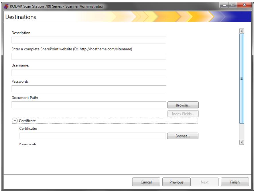
- Make an entry in the Description field that identifies the destination.
- Enter the address of the SharePoint server in the Enter a complete SharePoint website field. This field must contain a complete path to the SharePoint site.
- Make an entry in theUsername and Password fields.
- In the Documents Path field, enter the path to the folder where the documents will be scanned. If necessary, use the Browse button to help locate the folder.
- If there are required index fields for the selected library, select the Index Fields button. The Index Fields dialog box will be displayed that shows the required and optional index fields associated with the selected library.
NOTES:
-
A maximum of 5000 characters is allowed in the Index Notes field. If you enter more than 5000 characters, a warning message will not be displayed until you click in another area in the input field. At that point, when you click OK on the message, all of the data you entered in the Index Notes field will be deleted.
-
The first part of the document path is the library; anything after that, is a subdirectory. The library contains index fields.
- You must have a certificate before entering index fields (see Step 10).
- If the index field has a down arrow to the right of the index value, click it to display the value options.
The supported types of index fields are:
Single line of text
Multiple lines of text
Choice
Number
Currency
Date and Time
Lookup
Yes/No
Person or Group
Hyperlink or Picture
-
If the SharePoint site you want the user to access is secure, you will need to enter the certificate file and password by clicking the Certificate arrow. The SharePoint Certificate options will be displayed.
-
Enter the name of the certificate file in the Certificate field. The following file extensions are allowed: .cer, .crt, .der, .pfx, .p12, .p76, and p7c.
-
Enter the certificate password that the user should enter to open and decrypt the certificate file.
-
If your company requires the use of a proxy server before communicating with the SharePoint site, you must define these proxy settings by clicking the Proxy arrow.
- Enter the Proxy Address in the form of a fully qualified domain name (e.g., proxy.mycompany.com) or as an IP address.
- Enter theUsername and Password required to access the proxy server.
- If the proxy server is configured to communicate on a port other than Port 80, change or enter the value using the up and down arrows.
- If you want to add more SharePoint destinations within the same SharePoint destination group, select the Add icon and repeat Steps 5 - 14.
- To add another SharePoint destination group, select the SharePoint destination type and then click the Add icon, otherwise click Finish.
Adding a Kofax Front Office Server group
- Select Edit>Destinations. The Setup Destinations screen will be displayed.
- Click the Add icon to display the Destinations screen.
- Select Kofax Front Office Server.
- Click Next.
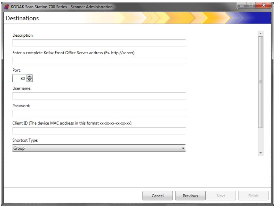
- Make an entry in the Description field that identifies the destination.
- Enter a server address in the Enter a complete Kofax Front Office Server address field.
- If the proxy server is configured to communicate on a port other than Port 80, select the correct value.
- Enter theUsername and Password required to access the Kofax Front Office Server.
- In the Client ID field, enter the Scan Station's MAC address (address format: xx-xx-xx-xx-xx-xx). This information can be found on the About screen on the Scan Station.
- Select Group or Personal from the Shortcut Type list.
-
Click Browse to locate the Shortcut name. The Select Shortcut dialog box will be displayed. Select the desired shortcut and click OK.
-
Click Index Fields. The Index Fields dialog box will be displayed. Index fields will vary based on each company's implementation of the Kofax Front Office Server.
- If the Kofax Front Office Server is secure, enter (or browse to) the name of the certificate file in the Certificate field. The following file extensions are allowed: .cer, .crt, .der, .pfx, .p12, .p76, and p7c.
- Enter the certificate password that the user will need to enter to open and decrypt the certificate file.
- If you want to add more Kofax Front Office Server destinations within the same Kofax Front Office Server destination group, select the Add icon and repeat Steps 5 - 14.
- To add another Kofax Front Office Server destination group, select the Kofax Front Office Server destination type and click the Add icon, otherwise click Finish.
This chapter provides procedures for adding and maintaining groups.
Groups are a collection of network users whose names can be extracted from the Active Directory Server. You can create a group from the contents of an existing Active Directory Server group and you can add individual users from the Active Directory Server to your group. For more information see "Configuring Active Directory Server settings" on page 41.
Assigning groups

Setting up groups makes it easier to restrict access to specific jobs to groups of users.
- Select Edit>Groups. The Setup Groups screen will be displayed.
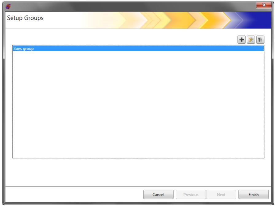
- Click the Add icon to display the Group screen.
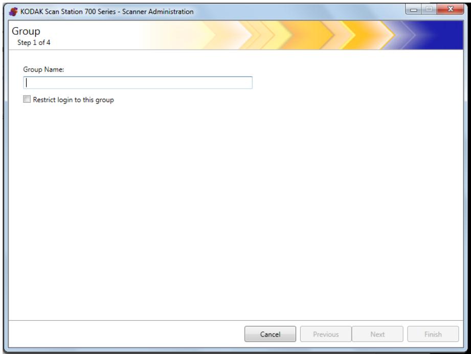
- Enter the desired group name.
- If you want to limit the use of the Scan Station to only the users defined in a group, check the Restrict login to this group checkbox.
- Click Next. Group names can be anything that is meaningful to you that defines a group of users.
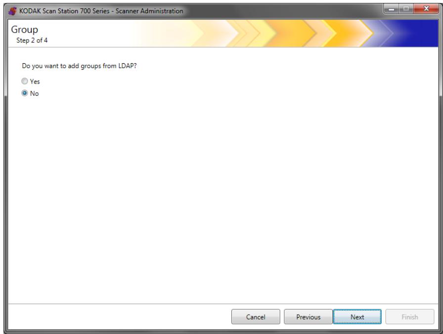
Adding Active Directory groups
- If you do not want to add groups from your Active Directory Server, click No, then click Next and continue with the section entitled, "Adding individual users".
- If you select Yes, the search fields will be displayed allowing you to find a group name from your Active Directory Server (LDAP); then continue with the steps below.
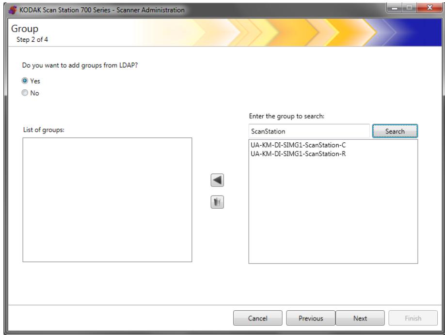
- In the Enter the Group to search field, enter the name of the group that you want to add and click Search.
NOTES:
-
If too many addresses are found that match the search criteria, you may want to refine your search by adding more information, such as the first name of the person you are searching; for example, "smith joe" instead of just "smith".
Wildcards can be added before and after the search criteria. -
Select the group(s) that you want to add from the list on the right and click the left arrow. The groups will be added in the List of groups box.
-
Repeat Steps 1 and 2 to add other groups to the list.
NOTE: If you want to delete a group from the List of groups, select the group you want to delete and click the Delete icon.
4. When finished, click Next.
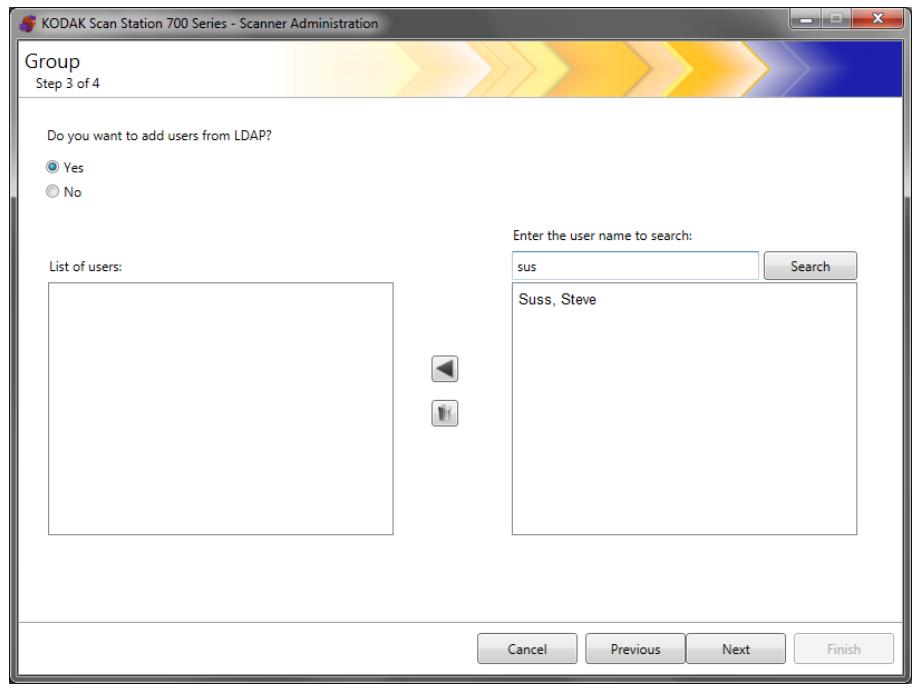
Adding individual users
-
If you do not want to add users from your Active Directory Server, click No, then click Next and continue with the section entitled, "Finishing your group configuration".
-
If you select Yes, the search fields will be displayed allowing you to find a user name from your Active Directory Server (LDAP); continue with the steps below.
-
Enter the name of the user you want to add to the group and click Search.
NOTES:
-
If too many addresses are found that match the search criteria, you may want to refine your search by adding more information, such as the first name of the person you are searching; for example, "smith joe" instead of just "smith".
Wildcards can be added before and after the search criteria. -
Select the user(s) to add to the group from the displayed list and click the left arrow.
-
When you are finished adding all users to your group, click Next
Finishing your group configuration
A listing of the groups and users will be displayed.
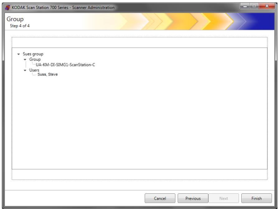
- Click Finish.
Because jobs are a collection of scan settings, index templates, destinations and groups of users, it is recommended that you create jobs after you have defined all of these settings.
1. Select Edit>Jobs.
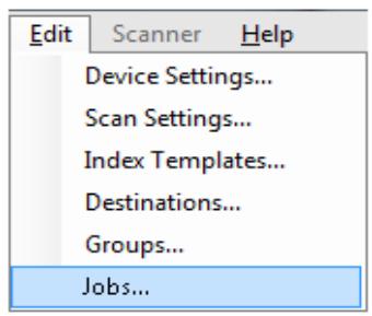
The Setup Jobs screen will be displayed.
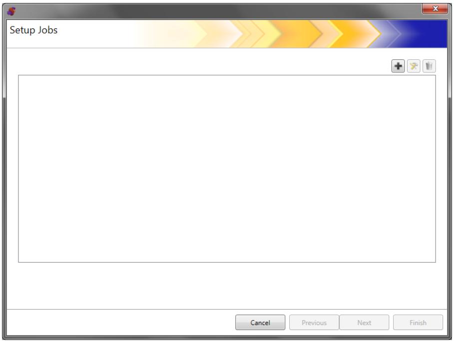
- Click the Add icon. The Job screen will be displayed.
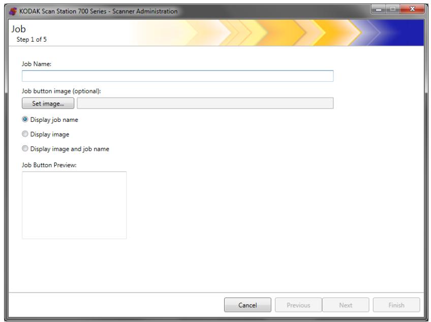
- Enter a job name. As you enter the job name, it will be displayed in the Job Button Preview box. This is how the name will appear on the Scan Station touchscreen.
- If desired, you can select an image file that you want to use as a background to the job name. Click Set image to locate the desired image file.
NOTES:
- The maximum image width is 200 pixels; the maximum image height is 130 pixels. Images will be automatically scaled to size.
- If you select an image file, the Display image and name option will automatically be selected.
-
The image that you select will copied into the configuration file.
-
Select one of the following:
-
Display Job name — only the job name will be displayed on the Job button.
- Display image — only the image will be displayed on the Job button.
- Display image and name — both the job name and image will be displayed on the Job button.
6. Click Next. The following screen will be displayed.
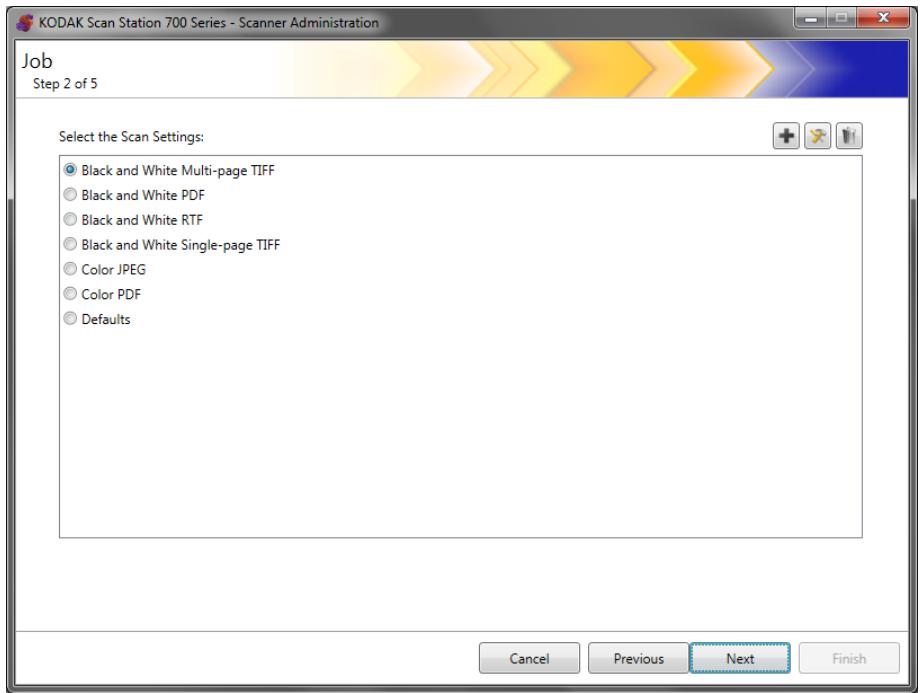
7. Select the Scan Settings you want to use for this job and click Next. The following screen will be displayed.
NOTE: You can also create new scan settings from this screen by clicking the Add icon.
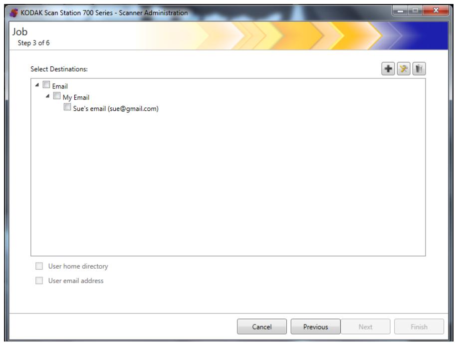
8. Select the destination(s) where want this job to be sent:
- You can select entire destination groups by clicking the highest level checkbox for the group.
-
You can select individual destinations by clicking on the destination(s) that is displayed below the group name.
-
If you want to create another destination on-the-fly, click the Add icon. The Destinations screen will be displayed allowing you to add another destination. For procedures on adding destinations see "Chapter 7 Create Destinations" on page 81.
-
Check User home directory if you want to automatically create a destination to the logged in user's home directory (as defined on the Active Directory Server Settings screen) when they log into the Scan Station.
-
Check Use email address if want to automatically create an email destination to the logged in user's email address (as defined on the Active Directory Server Settings screen) when they log into the Scan Station.
11. Click Next.
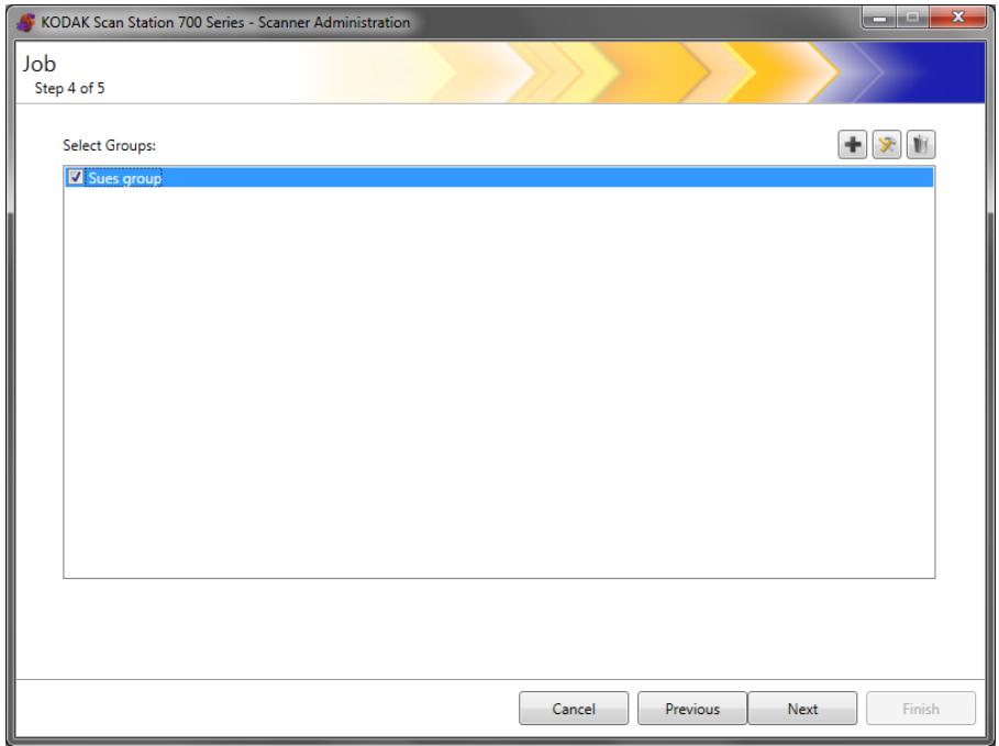
- Select the group you want to associate this job with and click Next.The Index Template screen will be displayed.
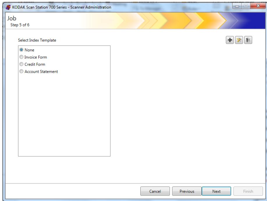
-
Select the Index Template that you want to associate with the job.
-
When finished, click Next. A summary of your job settings will be displayed.
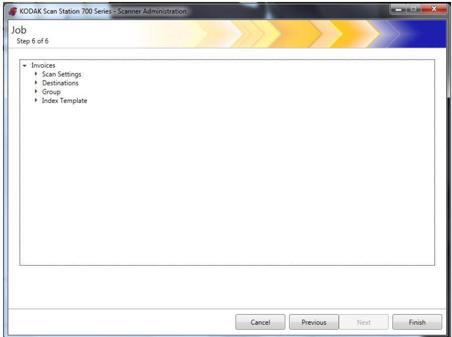
- Click Finish to return to the previous screen; then click Finish again to return to the Kodak Scan Station 700 Series - Scanner Administration main screen.
Once a job has been defined and the configuration has been uploaded to a Scan Station, the Jobs-only screen will be displayed on the Scan Station touchscreen instead of the normal user interface.
Job Queue Idle...
This chapter provides information for monitoring any Scan Stations that have been found on the network and configured.
Scanners tab
The Scanners tab contains the specific data to identify and connect to Scan Stations on a network.
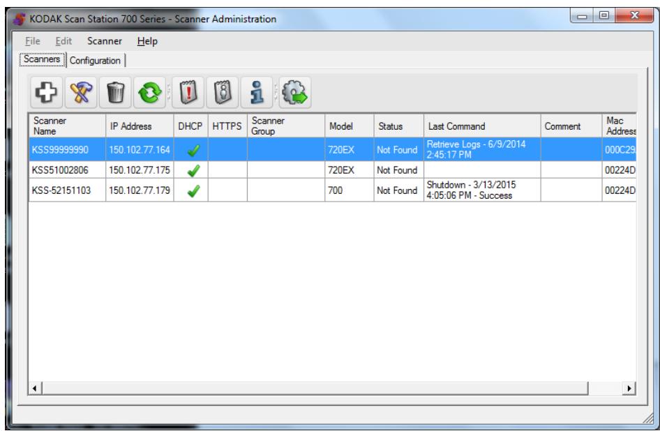
When the Scanners tab is active, you will have access to the Scanner menu. The options on the Scanner and Help menus are described in the section entitled, "Menu options" in Chapter 3.
The toolbar
The toolbar provides quick access to commonly used functions. The toolbar is always displayed. You cannot add, delete or move toolbar buttons.
| Icon | Description |
| + | Displays the Add Scanner dialog box, which allows you to choose Scan Stations that will be managed remotely. |
| × | Allows you to rename the selected Scan Station and set network settings. |
| √ | Allows you to delete the selected Scan Station from the list of managed Scan Stations. |
| Refreshes the grid to display the current state of the Scan Station: • Idle • Scanning • Processing images • Sending email • Saving • Printing • Scan completed • Error • Cancelled • Preview • Sending Fax • Receiving Fax • Powering down • Rebooting • Updating • In Use • Not found For a description of these states see “Scanner menu” on page 25. | |
| Retrieves, displays and allows the saving of the log file on the selected Scan Station. | |
| Displays and allows the saving of the transaction log file on the selected Scan Station. | |
| Displays detailed information about the selected Scan Station (e.g., software version, IP address, etc.). | |
| Uploads the selected configuration to the Scan Station. | |
Following is a description of the grid view columns
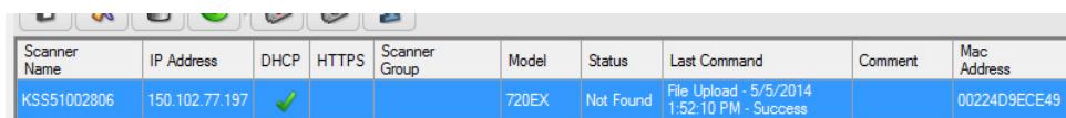
Scanner Name — displays the name assigned to the Scan Station.
IP Address — displays the IP address that is associated with the Scan Station.
DHCP — if the Scan Station is configured to retrieve the IP address using DHCP, this field will be checked. If the Scan Station is configured to use a statically defined IP address, this field will be blank.
HTTPS — if the Scan Station is configured to communicate using HTTPS, this field will be checked.
Scanner Group — Scan Stations can be associated with a group name. This column displays the group that the Scan Station is part of. This is set when adding a Scan Station.
NOTE: This is not the same as the group of users defined when creating and modifying configurations.
Model — displays the model number of the Scan Station (i.e., 730EX, 710, 5XX, etc.).
Status — displays the current status of the Scan Station (e.g., idle, scanning, updating, rebooting, etc.).
NOTE: When you press F5, the status of the discovered Scan Stations will be refreshed immediately.
Last Command — displays the last command that was issued by the administrator including the date, time and the success or failure of the action performed.
Comment — any comments added by the administrator when a Scan Station is added will be displayed in this column.
Mac Address — displays the unique identifier of the network adapter.
Network configuration options
Before you can start adding or discovering Scan Stations you must know the IP address or the device name; preferably both.
To get the name of your Scan Station:
- Be sure the Scan Station is on and operational.
- Click on the Information icon on the Scan Station to display the name and IP address if the Scan Station is connected to a network.
Adding a Scan Station
Before adding a Scan Station to manage remotely, it is suggested that you obtain the Scan Station name(s) and/or IP addresses and remote access password(s) of the Scan Stations you want to add.
NOTE: The Scan Station will only have an IP address if the Scan Station is connected to a network and has been configured.
As Scan Stations are added, the main screen will be updated.
- Select Scanner>Add Scanner. The Add Scanner dialog box will be displayed.
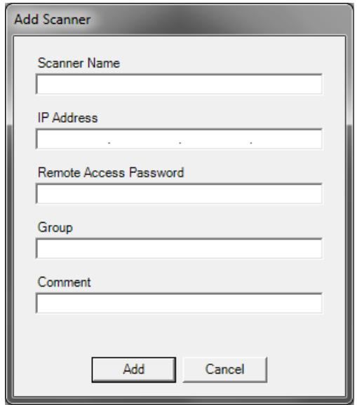
- Enter the name of the Scan Station in the Scanner Name field.
NOTE: Acceptable values in this field are: alphanumeric characters and a dash. No spaces or other symbols are allowed.
-
Enter the IP address. The IP address must be in IPv4 format xxx.xxx.xxx.xxx.
-
Enter the remote access password for the Scan Station. See the section entitled, "Configuration your device options" in Chapter 4 for more information.
NOTE: This field can be left blank. Leave this field blank if there is no remote access password set for the Scan Station.
-
If desired, enter a name of the group (or location). This name will be displayed in the grid view. For example, the Scan Station may be located in the main branch of a corporation.
-
If desired, enter any additional information that is important to you in the Comment field. For example, you can enter the name of the department where the Scan Station is located.
-
Click Add. The Scan Station name and information will be displayed on the Kodak Scan Station 700 Series - Scanner Administration main screen.
NOTES:
-
If the Scan Station is not found or if you are adding a Scan Station that will be installed on the network at a later time, the message, There was an error communicating with the device, would you like to Add it anyway? will be displayed. Click Yes to add the Scan Station.
-
If an incorrect IP address is entered, you may have to delete the Scan Station information from the Kodak Scan Station 700 Series - Scanner Administration main screen and add it again with the correct information.
-
Follow Steps 1 - 7 to add additional Scan Stations to this group.
The Discover Devices option allows you to scan a range of IP addresses to find and automatically register any Scan Station that has an IP address that falls within the defined range of addresses.
NOTE: The Discover Devices option only works on Scan Stations that have not had their remote access password set. This is the password that was set using the Scanner>Add Scanner menu option from the Scanner tab or from the Scanner>Remote Access Password menu option.
- Select Scanner>Discover Devices. The Discover Devices dialog box will be displayed.
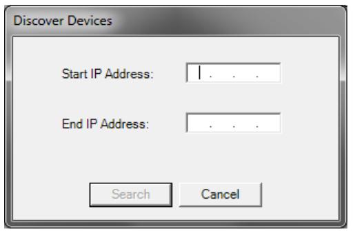
- Enter the first IP address where you want to start the search within a range of IP addresses in the Start IP Address field.
NOTE: As soon as you click on (or tab to) the End IP Address field, the end IP address will automatically be filled in with an address that is 10 greater than the start IP address (e.g., Start = 192.168.1.1, End = 192.168.1.10).
-
Enter the last IP address where you want to end the search in the End IP Address field.
-
Click Search. The search will begin. Depending on the range of the search, this process may take a few minutes. As IP addresses are found within the range, they will automatically be registered.
NOTE: If you select an address range that spans the upper two address segments of the IP address, it may take an exceedingly long time to discover devices (e.g., 192.168.1.1 - 192.169.1.1 or 192.168.1.1 - 193.168.1.1).
Modifying a Scan Station
- Select Scanner>Modify Scanner. The Modify Scanner dialog box will be displayed.

- Make any required changes.
NOTE: If you select Static IP Address, the Static IP Address dialog box will be displayed allowing you to change IP address settings.
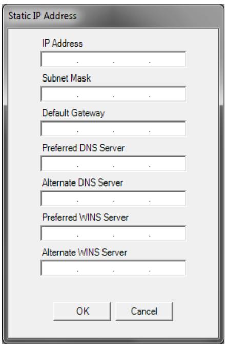
- Click OK.
- Click Update.
Deleting a Scan Station
- Select Scanner>Delete Scanner. The Delete Scanner dialog box will be displayed.
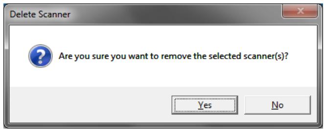
- Click Yes.
Changing a remote access password
- Select Scanner>Remote Access Password. This password is used by the Kodak Scan Station 700 Series - Scanner Administration to communicate with the Scan Station.
The Remote Access Password dialog box will be displayed.
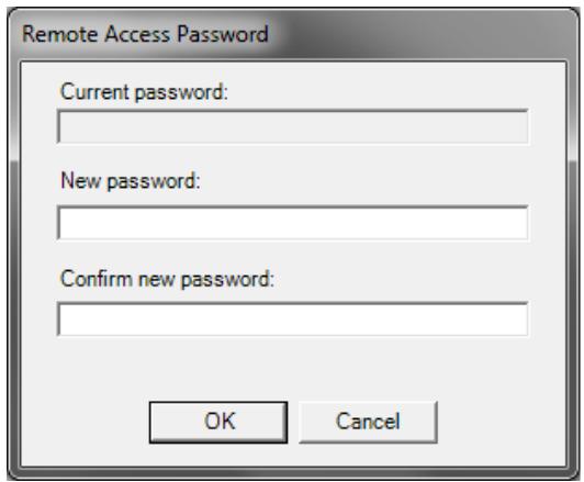
- Enter the Scan Station remote access password in the Current password field.
NOTE: This field will be grayed out if there is no remote access password set.
- Enter a new remote access password in the New password field.
- Re-enter the new remote access password in the Confirm new password field.
- Click OK.
Configurations/ configuration files
Configurations are a collection of settings that include: Device Settings, Scan Settings, Destinations, Groups and Jobs. Configurations are stored in two places: on the PC running the Kodak Scan Station 700 Series - Scanner Administration application and on the Scan Station(s) where the configuration file is uploaded. For more information on the difference between configurations and configuration files, see "Chapter 13 Glossary" on page 161.
Updating your Scan Station
There are five ways to update your Scan Station:
- Method 1. Uploading configurations and firmware updates using the Kodak Scan Station 700 Series - Scanner Administration application. The Scan Station will automatically recognize the new configuration or update package and perform an update automatically. See "Method 1" on page 124 for more information.
- Method 2. The configuration file and optional firmware update package is stored on a network drive and the Scan Station is configured to poll this shared folder at a specific day and time for updates. See "Method 2" on page 126 for more information.
- Method 3. The configuration file is stored on a USB drive inserted into a Scan Station. You will be asked if you want to update the Scan Station's configuration. If you select Yes, you will be prompted to update individual items. See "Method 3" on page 128 for more information.
- Method 4. The configuration file can be exported to a USB drive for use in configuring a Scan Station manually. When installing a configuration file using a USB drive, if the contents of the configuration file do not match the exact contents of the configuration file currently stored on the Scan Station, you will be prompted to update the Scan Station with the configuration on the USB drive. If you select No, the Scan Station will be placed into local administrative mode. At this point you can modify most of the Scan Station's settings and they will be updated as soon as you remove the USB drive. See "Method 4" on page 129 for more information.
- Method 5. The configuration file is stored on a USB drive with a firmware update package. Only the firmware will be updated with this method. See "Method 5" on page 130 for more information.
Method 1
The configuration file and optional update package is uploaded using the Kodak Scan Station 700 Series - Scanner Administration application. The Scan Station will recognize the new configuration file or update package and perform an update automatically.
Uploading configuration files
-
From the Scanners tab, select the Scan Station(s) from the grid view that you want to send the configuration to.
-
Select Scanner>Upload configuration. The Select configuration screen will be displayed.
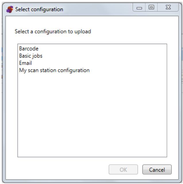
NOTE: If the selected configuration has changed, an asterisk will appear next to the configuration name. You must select File>Save before the configuration can be uploaded to the Scan Station.
- Select the configuration you want to upload and click OK.
NOTE: The Scan Station may be restarted automatically after the upload process depending on what configuration items have changed.
Uploading firmware
- Select the Scan Station(s) where you want to send new firmware.
NOTE: To select more than one Scan Station, use the Ctrl or Shift key and click the mouse button. The selected Scan Stations will be highlighted.
- Select Scanner>Upload Firmware. The Open dialog box will be displayed.
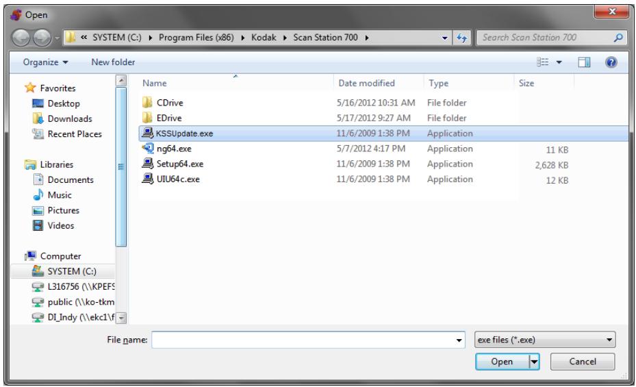
- Select the file that you want to upload and click Open.
NOTES:
- Only a KSSUpdate.exe file can be uploaded to the Scan Station.
- The message, Uploading, Please wait will be displayed while the file is being uploaded.
- If the Scan Station firmware and the KSSUpdate firmware are at the same revision level, no action will be taken.
- You can "roll-back" to an older version or update to a newer version of the Scan Station firmware. If an older version of the KSSUpdate.exe file is uploaded, the Scan Station will be rolled back to use the older version of the firmware. If a newer version is uploaded, the Scan Station will be updated with this newer firmware.
- You can obtain update packages from your Service Representative. Update packages will always be a file called KSSUpdate.exe.
The Scan Station can be configured to monitor a network folder where configurations and firmware updates are installed.
NOTE: If you have a Scan Station 710, it is suggested that you do not use this method because it will go into Low Power mode.
- Select the Configuration tab.
- Select the configuration that you want to modify.
- Select Edit>Device Settings.
- Check Device Options and click Next.
- Click the Automatic Configuration Schedule arrow and define the following values.
Automatic Configuration Schedule
Folder:
Day(s):
Time of Day:
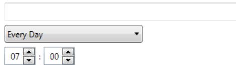
- Path to the folder where updates can be found.
- Which day of the week (Every Day, Every Monday, etc.).
- The time of day to check for updates (a 24-hour clock).
For example, you may want to monitor the folder \myserver\updates\myscanstationID on Every Monday, at 7:00 a.m.
There are two ways to remotely configure and update your Scan Station:
- Single file/folder update — create a single folder on the network where all Scan Stations are configured to monitor for updated configuration files. This way allows you to send a single configuration to all of the Scan Stations on a network at one time. This is recommended when all of your Scan Stations share the same configuration.
NOTE: When using remote update, some configuration settings (Scanner name, IP address and Remote Access Password), are ignored to avoid creating duplicate devices on your network.
- Multiple files/folder update — if each of your Scan Stations require a different configuration, it is recommended that a common folder is created on the network with sub folders underneath to store individual configuration files for each Scan Station on your network. Each Scan Station should then be configured to monitor the appropriate folder for updates.
On the defined day of the week and time, the Scan Station checks for the specified folder on the network, and if found, examines the contents of the folder looking for a KSS.xml file and an optional KSSUpdate.exe file. If the KSS.xml file and/or the KSSUpdate.exe file is found, the modification date and time will be compared to the last time a configuration was executed on the Scan Station. If the KSS.xml file and/or the KSSUpdate.exe file is more current, the configuration settings and/or new firmware update in the file are applied to the Scan Station.
NOTES:
- You can obtain update packages from the Kodak Alaris website or from your Service Representative. Update packages will always be a KSSUpdate.exe file.
-
To configure your network folder (the folder you specified in the Automatic Configuration Schedule: Step 5) for configuration and firmware updates:
-
Select the Configuration tab.
- Select a configuration file to write to the network folder.
- Select File>Export to write the configuration file to a network folder. The Save As screen will be displayed.
- Save the file on the network folder with the name KSS.xml and click Save.
- Copy KSSUpdate.exe to the network folder.
Method 3
This method requires a configuration file to be copied to a USB drive. When the USB drive is inserted into the Scan Station and recognized, you will be prompted to update the Scan Station configuration.
NOTE: If a local access password is set, you will be prompted to enter the local access password.
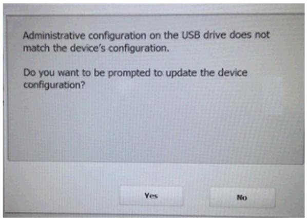
If you select Yes, you will be prompted to update individual items. When the configuration update is complete, click OK or remove the USB drive and the Scan Station will automatically be restarted.
This method must be repeated for each Scan Station.
To configure your USB drive for configuration updates:
- Select the Configuration tab.
- Select a configuration file to write to the USB drive.
- Select File>Export to write the configuration file to a USB drive. The Save As screen will be displayed.
- Save the file on the USB drive with the name KSS.xml and click Save.
Method 4
This method allows you to interactively select any of the Scan Station settings that are available in Settings mode on the Scan Station touchscreen and modify their values. When the USB drive with the configuration file is inserted into the Scan Station and recognized, you will be prompted to update the Scan Station configuration.
NOTE: If a local access password is set, you will be prompted to enter the local access password.
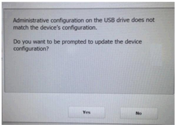
If you select No, the Scan Station will be placed into local administrative mode. At this point you can modify most of the Scan Station's settings and they will be updated when you remove the USB drive.
To configure your USB drive for configuration updates:
- Select the Configuration tab.
- Select a configuration file to write to the USB drive.
- Select File>Export to write the configuration file to a USB drive. The Save As screen will be displayed.
- Save the file on the USB drive with the name KSS.xml and click Save.
For more information see the Kodak Alaris publication entitled, "Configuring User Settings".
Method 5
This method requires an update package and a configuration file to be copied to a USB drive. When the USB drive is inserted into the Scan Station and recognized, if the update package is a different version than the currently installed version, you will be prompted to update the Scan Station firmware. Both the old version number and the version number of the update package will be displayed. If you decide to update the firmware, all the data found in the update package will be copied to the Scan Station and installed. When the installation is complete, click OK or remove the USB drive and the Scan Station will automatically be restarted.
When the Scan Station detects the configuration file (kss.xml) the message, Do you want to be prompted to update the device configuration? will be displayed. Select Yes and follow the prompts on the Scan Station if an update package (KSSUpdate.exe) is also on the USB drive and you want the Scan Station firmware updated.
NOTE: You can obtain update packages from your Service Representative. Update packages will always be a KSSUpdate.exe file.
To configure your USB drive for firmware updates:
- Select the Configuration tab.
- Select a configuration file to write to the USB drive.
- Select File>Export to write the configuration file to a USB drive. The Save As screen will be displayed.
- Save the file on the USB drive with the name KSS.xml and click Save.
- Copy KSSUpdate.exe to the USB drive.
Scan Station Security
Security is an important part of every day business. It is important that network devices do not allow intrusions from outside sources. The Scan Station 700 Series is configured to prevent external attacks from the Internet and from direct access by users. The following security features will block access to the Scan Station's operating system.
- The Scan Station uses a firewall and blocks nearly all incoming network traffic. Most inbound ports are blocked and will not respond to queries from the network.
- The Scan Station is also configured to respond to an echo (also known as a ping). This can be useful for diagnosing connectivity issues.
- The Scan Station is protected from external intrusions via the Scan Station USB ports. The operating system is configured to disable any auto-run action that could occur when presenting a new USB device to the system. The Scan Station recognizes the presence of a USB removable device, but will only open and read files that have been created and encrypted specifically for use by the Scan Station. Any file found on a removable device that is not properly encrypted will be ignored. This makes it almost impossible to introduce a virus by inserting a removable device with an infected executable.
- Viruses frequently find their way into a network-connected computer via email. Most viruses are spread as email attachments and infect a computer after the email has been opened and the attachment executed. The Scan Station does not receive any incoming emails, therefore, it cannot be infected in this manner.
- The Scan Station will only read a valid, encrypted configuration file.
- The underlying operating system is not available to the administrator or user. Updates to the operating system and/or the Scan Station firmware will be made available on the Kodak Alaris website http://www.kodakalaris.com/go/IMsupport) as needed.
- To help secure your Scan Station set the Remote Access Password For more information, see "Scanner menu" on page 25.
- You can require a user to login before scanning. For more information, see "Configuring your device options" on page 33.
Password protecting the Scan Station
You can require a user to log into the Scan Station before scanning. If you want to assign a local access password, see "Configuring your device options" on page 33. This security feature is intended for use in companies or departments that have sensitive material that they want to prevent being scanned and control distribution. Once the local access password is assigned, access will be blocked to all users who do not know the password. On a Scan Station that is password-protected, users will be given three tries to correctly enter the password. After the third failed attempt, the Scan Station displays a warning message for several minutes and then will return to the local access password entry screen.
The local access password also works in conjunction with the inactivity timer built into the Scan Station. In normal operation, after a Scan Station has been used and has remained idle for 30 seconds, a warning screen will be displayed asking the user if they want to reset all Scan Station settings to the default state. If no selections are made, then after two more minutes of inactivity, the device will be returned to its default state. At this point, the user will need to re-enter the local access password to use the Scan Station.
NOTE: As an added measure of security, individual users can be required to log into the Scan Station. See "Configuring Active Directory Server settings" on page 41.
Retrieving and clearing files
Options for retrieving and clearing log files are accessible by selecting Scanner>Device.

Retrieving the Scan Station log file
The Retrieve Logs option allows you to save the log file retrieved from the selected Scan Station. The log file extension is .log. The log file contains information about the Scan Station (e.g., document jams, etc.).
Two methods are available for saving log files:
- Method 1. Using the Kodak Scan Station 700 Series - Scanner Administration application.
Method 2. Using a USB drive.
Method 1
- Select the Scan Station.
NOTE: To select more than one Scan Station, use the Ctrl or Shift key and click the mouse button. The selected Scan Stations will be highlighted.
- Select Scanner>Device>Retrieve Logs. The log file for the selected Scan Station will be displayed.
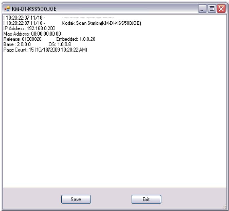
- Click Save. The Save As dialog box will be displayed.
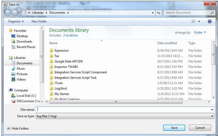
- Enter a file name for the log file and click Save.
Method 2
- Create a configuration file (kss.xml) on a new USB drive.
- Insert the USB drive into the Scan Station's USB port to put the Scan Station into local administrative mode. The following message will be displayed.
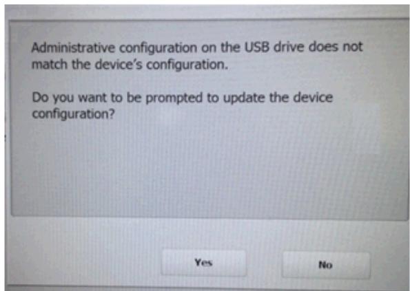
- Select No. The Scan Station will display the Settings icons.
- Using the arrows, scroll until the Diagnostics icon is displayed and selected.
- Select Save Logs and click Yes to save the log file to the USB drive.
The analog.log, kss.xml.log and NTBT.log.txt files will be saved to the USB drive.
Clearing a log file
To clear a log file:
- Select the Scan Station(s) where you want to clear the logs.
- Select Scanner>Device>Clear Logs. The following message will be displayed, Are you sure you want to clear the log files of the selected Scanner?
- Click Yes.
Retrieving the Scan Station transaction log file
The Retrieve Transaction Logs option allows you to save the transaction log file retrieved from the selected Scan Station. The transaction log file extension is .xml. The transaction log file contains actual Scan Station transactions (i.e., destinations, time of transaction, recipient, sender, status of the transaction, number of pages scanned).
Two methods are available for saving log files:
- Method 1. Using the Kodak Scan Station 700 Series - Scanner Administration application.
Method 2. Using a USB drive.
Method 1
- Select a Scan Station.
- Select Scanner>Device>Retrieve Transaction Logs. The transaction log file for the selected Scan Station will be displayed.
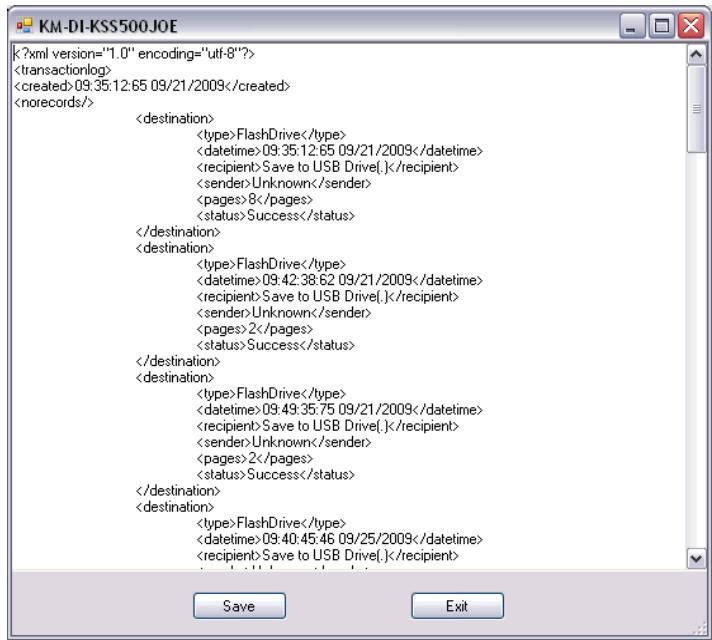
- Click Save. The Save As dialog box will be displayed.
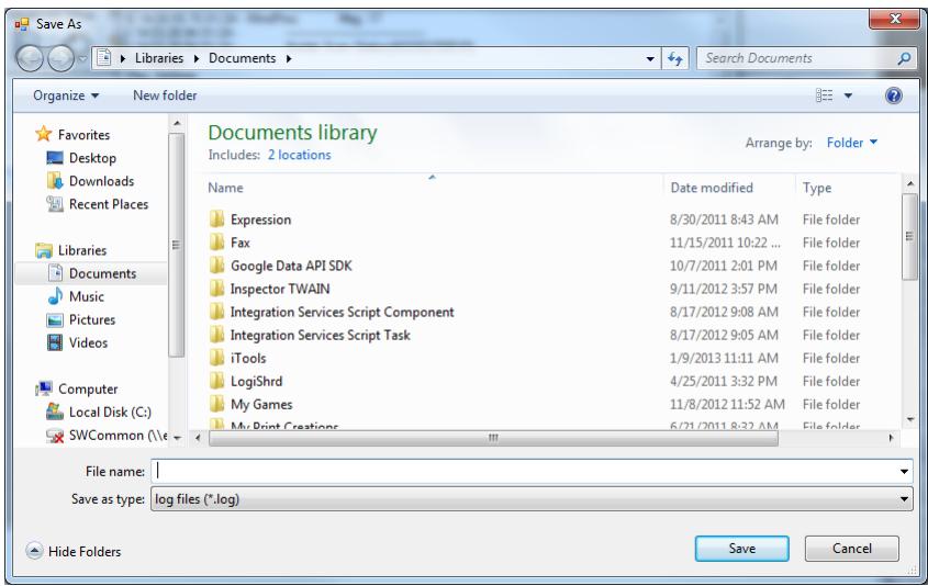
- Enter a file name and click Save.
Method 2
- Create a configuration file (kss.xml) on a new USB drive.
- Insert the USB drive into the Scan Station's USB port to put the Scan Station into local administrative mode. The following message will be displayed.

- Select No. The Scan Station will display the Settings icons.
- Using the arrows, scroll until the Diagnostics icon is displayed and selected.
- Select Save Transaction Log and click Yes to save the transaction log file to the USB drive. The following message will be displayed, The transaction log has been copied to your USB drive. Do you wish to clear the transaction log?
- Click Yes to clear the log.
The
Clearing a transaction log file
To clear a transaction log file:
- Select the Scan Station(s) that you want to clear the transaction logs.
NOTE: To select more than one Scan Station, use the Ctrl or Shift key and click the mouse button. The selected Scan Stations will be highlighted. - Select Scanner>Device>Clear Transaction Logs. The following message will be displayed, Are you sure you want to clear the transaction log files of the selected Scanner?
- Click Yes.
Saving all log files
The Save All Logs option allows you to retrieve any available log files found on the selected Scan Station(s). You will be asked for a directory where you want to store the log files. The directory will contain folders of the selected Scan Station names and the retrieved log files will be placed in these folders.
Scan Station details
Updating the Time/Date remotely
To view the details of a selected Scan Station:
- Select Scanner>Device>Details. The Details dialog box will be displayed with detailed information about the selected Scan Station (e.g., software version, IP address, etc.).
If your network has access to an NTP server, you can configure all of your Scan Stations to synch their internal clock with the NTP server by using the Update Time/Date option.
- Select Scanner>Device>Update Time/Date. The following dialog box will be displayed.
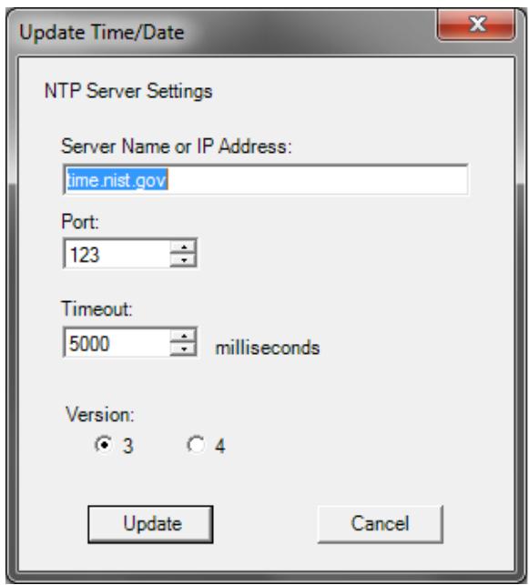
- Enter the Server Name or IP Address of the NTP server from which you want to synchronize the Scan Station's clock.
- Select the port of the NTP server. The default is 123.
- Enter the amount of time (in milliseconds) after which the Scan Station will stop attempting to synchronize its internal clock (500 milliseconds = 1/2 second). Do not change the default, unless you experience problems.
- Select Version 3 or 4 of the NTP server.
- Click Update.
Turning off one or more Scan Stations
Occasionally it may be necessary to turn off a Scan Station(s) for a particular reason (e.g., scheduled downtime on the network, a scheduled power outage or because a particular Scan Station may require maintenance). When this becomes necessary, you can turn off any Scan Station remotely.
- Select the Scan Station(s) you want to power off.
- Select Scanner>Power Options>Power Off. The message, Are you sure you want to power down the selected Scanner? will be displayed.
- Click Yes to continue to power down the Scan Station(s).
NOTE: You can also power off or restart the Scan Station by pressing the Power button.
Restarting one or more Scan Stations
Occasionally it may be necessary to restart a Scan Station(s) for a particular reason (e.g., after loading new firmware). When this becomes necessary, you can restart any Scan Station remotely.
-
Select Scanner>Power Options>Reboot. The message, Are you sure you want to reboot the selected Scanner? will be displayed.
-
Click Yes to continue to restart the Scan Station(s).
NOTE: You can also power off or restart the Scan Station by pressing the Power button.
If there are jobs in the background processing queue when you restart or turn off the Scan Station using the Kodak Scan Station 700 Series - Scanner Administration application (Scanner>Power Options), a list of options will be displayed.
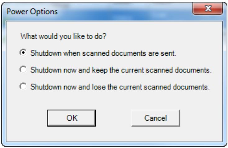
- Select the desired option and click OK.
Moving one or more Scan Stations
If you need to move a Scan Station(s) from one network to another.
- Power off the Scan Station.
- Unplug the power cord and network cable.
- Move the Scan Station(s) to the desired location.
- Make the power cord and network cable connections.
- Power on the Scan Station(s).
Opening the Scan Station cover
- Before opening the Scan Station cover, be sure the output tray cover is lowered.
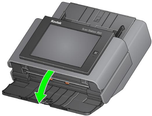
- Press and hold the Scan Station cover release lever and pull the Scan Station cover open.
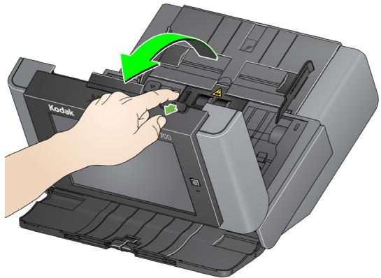
- When you finish cleaning the Scan Station or replacing a part, close the Scan Station cover with both hands.
Cleaning procedures
Your Scan Station needs to be cleaned periodically. If your documents do not feed easily, if several documents feed at the same time or if streaks appear on your images, it is time to clean your Scan Station. The section entitled, "Supplies and consumables" at the end of this chapter provides a listing of the supplies required to clean your Scan Station.
IMPORTANT: Use only non-flammable cleaners such as those provided through Kodak Parts Services. Do not use household cleaners.
Allow surfaces to cool to ambient temperature before use. Do not use cleaners on hot surfaces.
Use adequate ventilation. Do not use cleaners in confined areas.
Do not use air, liquid or gas spray cleaners. These cleaners displace dust, dirt and debris to other locations within the Scan Station.
Do not use alcohol-based cleaners on the tires or imaging guides.
NOTES:
- Before beginning cleaning procedures, turn the Scan Station power off and disconnect the electrical power.
- Wash your hands with soap and water after performing maintenance procedures.
Cleaning the rollers
- Open the Scan Station cover.
- With a roller cleaning pad, wipe the feed rollers from side to side. Rotate the feed rollers to clean the entire surface.
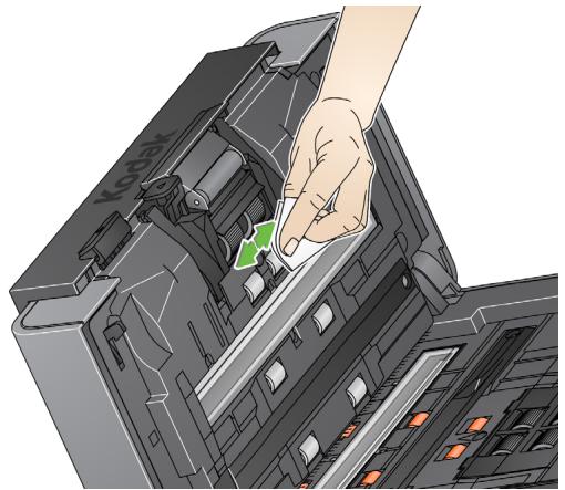
- Dry the rollers with a lint-free cloth.
Cleaning the separation module
The separation module should be removed from the Scan Station for best cleaning results.
- Push the separation module up to snap out and lift it out of position.
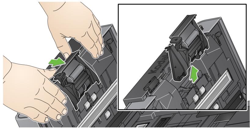
- Manually rotate and wipe the separation module tires with a roller cleaning pad.
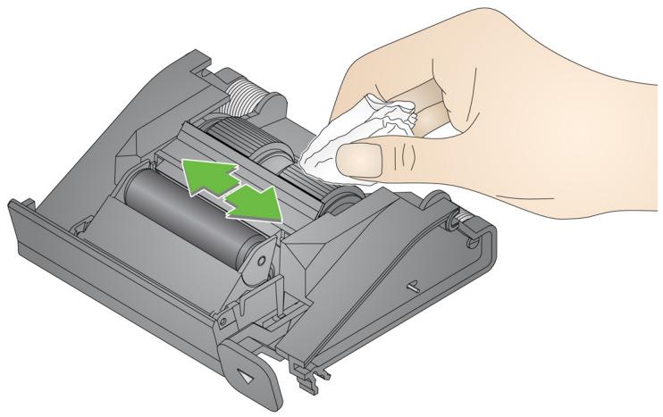
- Inspect the separation module.
If the separation module tires show signs of wear or damage, replace the tires or the separation module. See "Replacement procedures" on page 147 for more information.
- Insert the separation module by aligning the tabs with the slots and snapping it into position.

Cleaning the feed module
NOTE: The paper present sensor is located to the left of the feed module. Be careful not to damage the paper present sensor when removing or cleaning around the feed module.
- Pull against the raised edge of the feed module cover and lift it up and out of position.
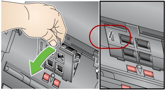
- Rotate the feed module forward and push it to the left to lift it out of position.

- Manually rotate and wipe the feed module tires with a roller cleaning pad.
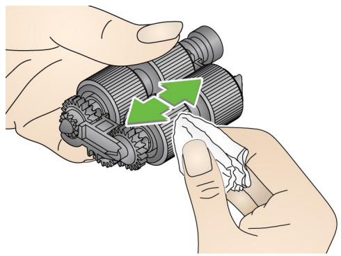
- Inspect the feed module.
If the feed module tires show signs of wear or damage, replace the tires or the feed module. See "Replacement procedures" on page 147 for more information.
-
Using a vacuum or cleaning pad, remove dust and debris from the feed module area.
-
Reinstall the feed module by aligning the pins and pushing it toward the left to fit it into position. Be sure the gears are aligned and it snaps into place. Roll the feed module back into place.
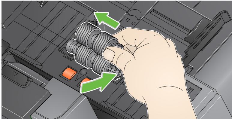
- Reinstall the feed module cover by aligning the tabs with the slots and pushing it back into position until it snaps into place.
Vacuuming the Scan Station
Before cleaning the imaging area, it is suggested that you vacuum the inside of the Scan Station to remove any dust and debris.
Cleaning the imaging area
- Wipe the upper and lower imaging area using a Staticide wipe. Be careful not to scratch the imaging area when cleaning.
IMPORTANT: Staticide wipes contain isopropanol which can cause eye irritation and dry skin. Wash your hands with soap and water after performing maintenance procedures. Refer to the MSDS for more information.
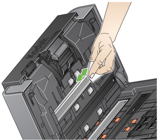
- Wipe the upper and lower imaging area again using the reusable optics cleaner pad to remove any streaks.
- When finished, close the Scan Station cover with both hands.
Running a transport cleaning sheet
- Remove the wrapping from the Transport Cleaning Sheet.
- Adjust the side guides to fit the cleaning sheet.
- Place a transport cleaning sheet in the input tray (adhesive side facing you) in portrait orientation.
- Select any job or select a destination and touch the green Scan button.
- After the transport cleaning sheet is scanned, turn it over (adhesive side facing the input tray) and scan it again.
- Open the Scan Station cover and wipe the imaging area with a lint-free cloth.
- Close the Scan Station cover with both hands.
- Check your image quality.
- If necessary, repeat this procedure until all residue is removed from the rollers.
NOTE: When a transport cleaning sheet gets very dirty, discard it and use a new one.
Replacement procedures
Kodak Scan Stations use replaceable tires that can feed a wide range of document types, sizes and thicknesses. Tire life and performance will vary based on the customer's document set, the frequency of cleaning the paper path and tires, and following the recommended schedule for changing tires. Nominal tire life is approximately 125,000 pages. Usage figures are not guaranteed. Customer operating environments, document type, the condition of documents being scanned, and not following the recommended cleaning and replacement procedures, can cause the life of the consumables to vary. You should change the tires if you notice an increase in multiple feeds, stoppages, or a decrease in feeder performance that is not resolved by following the cleaning procedures.
NOTES:
- Before beginning replacement procedures, turn off the Scan Station and disconnect the electrical power.
- For certain paper types (such as carbonless paper or newsprint), failure to clean regularly, and/or use of non-recommended cleaning solvents can shorten roller life.
Replacing the separation module and tires
- Push the separation module up to snap out and lift it out of position.
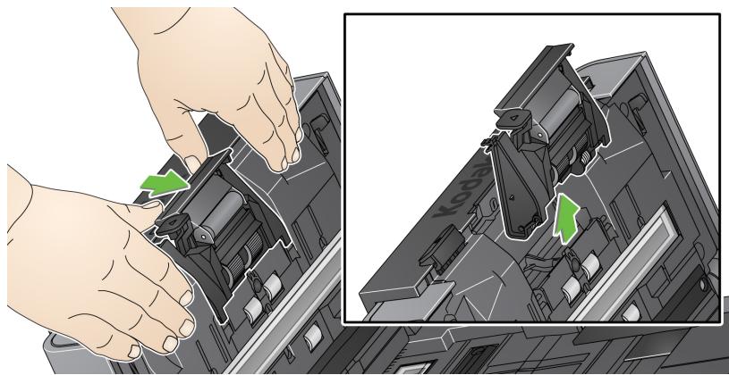
- If you are replacing the separation module, insert the new separation module by aligning the tabs with the slots and snapping it into position.
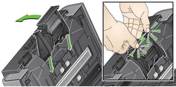
If you are replacing the tires, continue with Step 2.
- Holding onto the separation module, rotate the release lever back so you can access the separation roller.
CAUTION: Use caution as the release lever is spring-loaded and will snap back if you do not hold it in place.
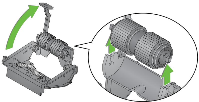
- Remove the separation roller from the separation module housing.
- Remove each tire by sliding the tire off the core.
- Install each new tire by gently pulling it over the core.
IMPORTANT: Do not overstretch the tire, it may tear. - Reinstall the separation roller in the separation roller housing. Be sure the separation roller snaps into place.
- Reinstall the separation module by aligning the tabs with the slots and snapping it into position.
Replacing the preseparation pad
- Remove the separation module from the Scan Station by following the steps previously described in "Replacing the separation module and tires".
- Hold the separation module in both hands and locate the two tabs which protrude slightly from the back of the separation module.
- Push down on the tabs until the pre-separation pad protrudes slightly from the front of the separation module.
- Grasp the pre-separation pad and pull it out of the separation module.
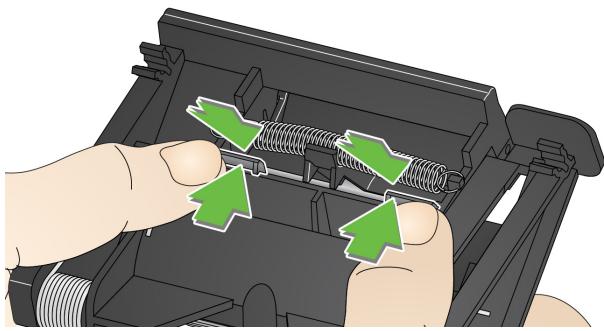
- Discard the worn pre-separation pad.
- Align the side tabs of a new pre-separation pad with the slots on the separation module.
- Push the pre-separation pad firmly in the slots until the pre-separation pad flap rests lightly against the separation module tires.
- Reinstall the separation module by aligning the tabs with the slots and snapping it into position.
NOTE: The paper present sensor is located to the left of the feed module. Be careful not to damage the paper present sensor when removing or cleaning around the feed module.
- Pull against the raised edge of the feed module cover and lift it up and out of position.
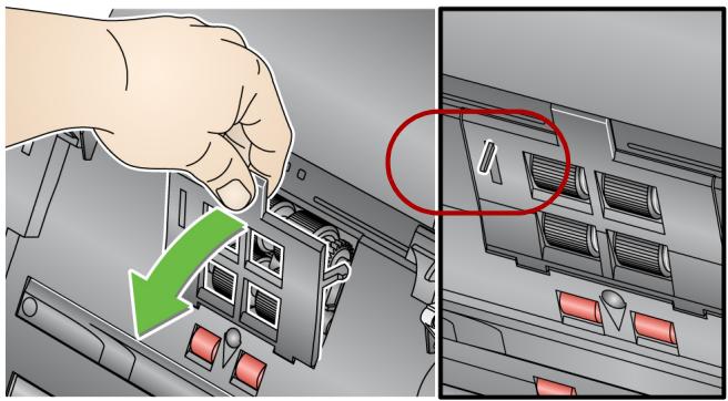
- Rotate the feed module forward and push it to the left to lift it out of position.
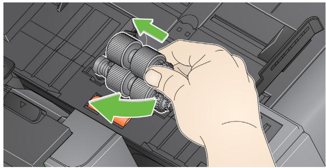
-
If you are replacing the feed module, insert the new feed module by aligning the pins and pushing it toward the left to fit it into position. Be sure the gears are aligned and it snaps into place, then go to Step 8.
If you are replacing the tires, continue with Step 3. -
Remove one core assembly by lifting up and out of position.
- Remove each tire by sliding the tire off the core.
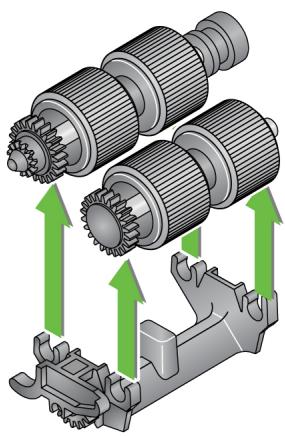
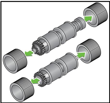
- Install each new tire by gently pulling it over the core.
IMPORTANT:Do not overstretch the tire; it may tear. - Replace the core assembly in the feed module. You may need to slide the shaft to the right or left so the core fits properly within the feed module housing.
- Repeat the replacement procedure outlined above for the other core assembly.
- Reinstall the feed module by aligning the pins and pushing it toward the left to fit it into position.
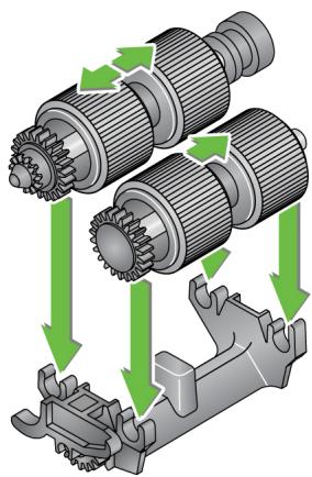
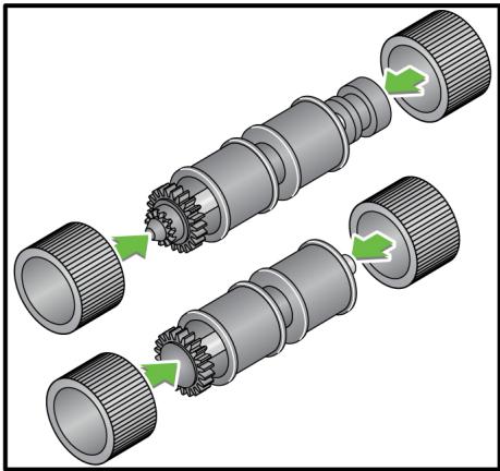
- Reinstall the feed module cover by aligning the tabs in the slots and pushing the feed module cover down until it snaps into place.
Adjusting the pre-separation roller tension
If you are experiencing multi-feeds or document jams, it may be necessary to adjust the pre-separation roller tension.
- Remove the separation module by following the steps described previously in "Replacing the separation module and tires".
- Locate the spring on the separation module.
- Lift the spring from the holder and move it to the left or right as desired to adjust the tension.
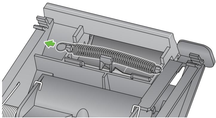
- When finished, reinsert the separation module by aligning the tabs with the slots and snapping it into position.
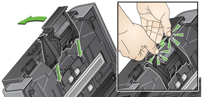
Supplies and consumables
Contact your Scan Station supplier to order supplies.
| Description | CAT No. |
| Kodak Feed Rollers (quantity: 12) | 148 4864 |
| Kodak Separation Module | 173 6115 |
| Kodak Feed Module | 826 9607 |
| Kodak Roller Cleaning Pads (quantity: 24) | 100 2716 |
| Kodak Digital Science Transport Cleaning Sheets (quantity: 50) | 169 0783 |
| Staticide Wipes (quantity: 6 boxes of 24) | 896 5519 |
NOTE: Items and catalog numbers are subject to change.
Safety Data Sheets (SDS) for chemical products are available on the Kodak Alaris website at: www.kodakalaris.com/go/ehs. When accessing the SDSs from the website, you will be required to provide the catalog number of the consumable you want the Safety Data Sheet for.
Problem solving
Occasionally you may encounter a situation with your Scan Station where it may not function properly. Use the chart below as a guide to check possible solutions to help you resolve the situation before calling Technical Support.
| Problem | Possible Solution |
| Regular cleaning and Scan Station maintenance is required to keep documents scanning smoothly and provide optimum image quality. Follow the recommended cleaning procedures in Chapter 11, Maintenance for best Scan Station performance. | |
| Documents are jamming or multiple documents are feeding | Make sure that: • the side guides are adjusted for the correct document width. • the input tray does not have more than 75 sheets of 80 g/m2(20 lb.) paper in the tray. • the output tray is adjusted for the length of the documents you are scanning. • all documents meet the specifications for size, weight and type as outlined in Appendix A, Specifications. • the Scan Station and rollers are clean. • the rollers are not worn and do not need to be replaced. • the spring on the pre-separation module is adjusted to the proper tension. See “Adjusting the pre-separation roller tension” on page 152. • the feed module and pre-separation module is installed properly and securely in place. See the procedures in “Chapter 11 Maintenance” on page 141. To remove a document jam: IMPORTANT: Be sure the output tray is lowered before opening the cover. Do not pull the jammed document out of the Scan Station; open the Scan Station cover first. • Press and hold the Scan Station cover release lever and pull the Scan Station cover open. • Remove any jammed document(s) from inside the Scan Station. • Close the Scan Station cover and resume scanning. |
| Scan Station will not scan/feed documents | Make sure that: • the power cord is plugged securely into the back of Scan Station and the wall outlet. • the power switch is on; LED is blue. • the wall outlet is not defective (call a licensed electrician). • document(s) is making contact with the feed rollers. |
| No images are being displayed | Be sure the documents you are scanning are placed properly in the input tray based on how your job is configured. For example, if your job is set up to scan documents one-sided - face down, be sure the side you want to scan is facing the input tray (not facing you). If you are unsure as to how the job is configured, contact your System Administrator. |
| Roller marks appear on the document after scanning | Clean the rollers. See the procedures in "Chapter 11 Maintenance" on page 141. |
| Images have black background bleed through | When scanning translucent documents, black bleed-through may be displayed on the image. To minimize this, adjust the Contrast value on the Scan Settings screen. |
| Red, green or blue streaks are running through a color photo | The Scan Station is dirty and needs to be cleaned. Refer to "Cleaning procedures" on page 142. |
| Image quality is poor or decreased | Clean the Scan Station. Refer to "Cleaning procedures" on page 142. |
| Network Authentication Issues | Possible Solution |
| The Scan Station 700 Series - Scanner Administration application cannot communicate with the Scan Station when the Scan Station is powered up and is left idle for more than 15 minutes (or your set value) then goes to into power saver mode. | Wake On LAN (WOL) is designed to work using a broadcast address, thus it is more likely to work reliably when a Scan Station and the Scanner Administration application are on the same subnet. It can be used across subnets but it will only work if the ARP tables in routers/ switches on the network still contain information about the Scan Station. This information is volatile and the longer a Scan Station is in power saver mode, the less likely it will work. However, if the Scan Station is down for only a short time, quite often things will work fine. These limitations are not limited to Scan Station. This is a network infrastructure restriction.It is suggested that you assign a Static IP address to the Scan Station. |
| Cannot receive incoming faxes even though the Scan Station is properly configured | • Be sure you are connected to an analog phone line (not a digital phone line).• Verify the following:1. Make sure the cable is plugged into the RJ11 port in the back of the Scan Station. (This port is available only on Scan Station 730EX units with a serial number earlier than 52190000.)2. Be sure that the fax options are configured correctly for receiving faxes. For more information, see "Receiving faxes at the Scan Station 730EX" on page 47. |
| Domain authentication | Check the following to verify for correct connections in a network domain.These settings can be accessed by selecting the Configuration tab and selecting Edit>Device Settings. Check Device Options and click Next. Open the Network Destination Credentials option and verify the networkUsername, Password and Domain name.If these are not set correctly, the Scan Station will not be able to access the domain. |
| Device name is not unique | All Scan Stations have a default name assigned from the factory. The default name is: KSSxxxxxxxxxx (where xxxxxxxx represents the Scan Stations' serial number). This ensures that all Scan Station device names are unique. If you leave this option blank when you are configuring the Device Name, the Scan Station will continue to use the default factory-installed device name. If you want to change the default Device name, you must select a unique name. |
| Network Authentication Issues | Possible Solution |
| Checking the account name and password | If your Scan Station does not scan to a network location or stops scanning to a network location, you may have issues with the logon credentials supplied to the Scan Station. When creating network accounts that are assigned to the Scan Station, certain properties may be applied to the account such as, Change password upon first log on and Change password every xx days. It is recommended that these types of restrictions are not applied to accounts that will be used for a Scan Station. A network administrator can verify the account settings assigned to a Scan Station by using the credentials to log on to a normal network computer. If you are unable to logon to your network using these credentials, there may be a problem with the account. A network administrator can modify the settings. It may also be necessary to reset the password. |
| Workgroup authentication | If having trouble writing to a locally shared folder in a workgroup, check the permissions attached to the folder from the PC on the network that is sharing the folder. Make sure the folder's Permissions allow access to the Scan Station. |
| Email Authentication | Verify that the authentication method defined in the Scan Station settings match the authentication method of your SMTP server. Currently the Scan Station supports simple password, NTLM and Challenge Response. These settings can be verified by using a Windows mail client such as Outlook Express and creating a mail account that uses the username and password assigned to the Scan Station. |
| SMTP server problems | Follow these procedures to resolve issues with the SMTP server address: · Verify that other email clients on different device are able to send mail and reach the SMTP server. · Change your configuration file to identify the SMTP server with an IP address instead of a Fully Qualified Domain Name (FQDN). If you are able to reach the SMTP server with the IP address but not the FQDN, you have a DNS resolution problem. Check to make sure you are able to reach the DNS server and that it correctly resolves FQDNs. · Your SMTP server may require SSL or TLS. See your network administrator if you need to select either of these options. |
| Finding the SMTP server address | Use the following procedure to find the SMTP server address: · Examine the settings of the mail client in use on your workstation to find the IP address or Fully Qualified Domain Name for the SMTP server, or · examine the emails sent from an internal mail client and display the full email header, or · ask the administrator of the mail server for this information. |
| Verifying an SMTP server address | In the Kodak Scan Station 700 Series - Scanner Administration application, use Test Connection. Send mail to the SMTP server using a mail client application from a PC attached to the same network as the Scan Station. · If the mail was successfully sent and received, the SMTP server address is valid. · If you are unable to send an email to the SMTP server, review any error messages you receive. It is possible the SMTP server address is valid, but the authentication credentials are not valid. |
| FTP authentication | Scanning to FTP sites may require the configuration of two sets of credentials: proxy credentials and FTP server credentials. If your network environment requires the use of a proxy server to access external FTP sites, you need to configure appropriate proxy credentials that include username, password and authentication method. Proxy authentication methods include: User after login and None. You may also need to configure a username and password to access the FTP server. The Scan Station also supports anonymous FTP. |
| Your network Domain name | To find and set the domain name your Scan Station will use, follow these steps: 1. From a PC logged onto the same network/domain that the Scan Station will use, right-click on Computer and select Properties. On the next screen, select Advanced System Settings to display the System Properties window. 2. Select the Computer Name tab. |
| Scan to Network Share Issues | Possible Solution |
| Unable to scan to network folder | Using another computer on your network with Windows 7, Windows 8 or Windows 10, ping the NETBIOS computer name of the Share destination. For example, if your destination is \Servername\Sharename, ping Servername. ·If you get a reply to your ping, NETBIOS name resolution is working and the problem may be with the share name or permissions to the share. ·If you do not get a response, NETBIOS name resolution is not working. If you know you have a valid shared folder, you can use either the IP address or, in some cases, the Fully Qualified Domain Name in place of the server name. For example, if the IP address of the computer that hosts the share is 100.100.100.1 and the Fully Qualified Domain Name is server.company.com you could trying using either: \100.100.100.1\Sharename or \server.company.com\sharename One of these two usually works in place of NETBIOS names in the destination address for the share. ·If NETBIOS name resolution is not working and it is your only choice for defining network paths, ask your network administrator about changing your router's configuration. Many organizations block TCP/IP traffic over ports 137 and 139, which are the TCP ports Microsoft uses for NETBIOS over TCP/IP. When these ports are blocked, you cannot resolve a NETBIOS name if the path to the destination address crosses router (e.g., subnet) boundaries. ·Using another computer on your network with Windows 7, Windows 8 or Windows 10, open Windows Explorer and map a network drive to \Servername\Sharename. If this does not work, check the Permissions of the shared folder on the host computer. Make sure either Everyone or the user account for the Scan Station has Read and Write permissions to the shared folder. ·To verify a network shared folder is accessible on your network, from another PC on your network, click Start>Run. In the Open field, type in the server name (e.g., \servername) and click OK. If the server is accessible, then all available shared resources will be displayed. Select one of these shared resources to verify it is active. If not, correct the Permissions on the shared folder before trying to access the folder from the Scan Station. |
| There was an error reading the selected certificate. Please select a different certificate or see your system administrator for more information. | You specified a certificate that is on a drive that is no longer accessible. Go back to the Kodak Scan Station 700 Series - Scanner Administration, select Destinations, select SharePoint as your destination and set the Certificate field to an accessible drive. |
Indicator lights
The power button is illuminated blue when the Scan Station is on and ready. Following is a description of LED status:
| LED | Status |
| Steady blue | • Briefly displayed when the Scan Station is first turned on. • Scan Station is on and ready to scan. |
| Flashing blue | • Indicates the Scan Station is initializing from powering on or warming up and preparing to scan. • Low power mode. |
| Flashing or steady red | • Briefly displayed when the Scan Station is first turned on. • Indicates a Scan Station error, such as the Scan Station cover is open. |
Saving error log files
You may be asked by Service personnel to send the log files as an email attachment for further diagnostics. Create a configuration file on a new USB drive.
- Insert the USB drive into the Scan Station's USB port to put the Scan Station into local administrative mode. The Scan Station will display the Settings icons.
- Using the arrows, scroll until the Diagnostics icon is displayed and selected.
- Select Save Logs and click Yes to save the log file to the USB drive.
The analog.log and kss700.xml.log files will be saved to the USB drive.
You can also use the Kodak Scan Station 700 Series - Scanner Administration application to save log files.
- Launch the Kodak Scan Station 700 Series - Scanner Administration application.
- Click the Scanners tab.
- Select Scanners>Device and select the type of file you want to save.
Contacting Service
- Visit www.kodakalaris.com/go/IMsupport to obtain the most current phone number for your country.
- When calling, please have the following information ready:
A description of your problem.
- The Scan Station serial number.
Authentication credentials — username, password and optional domain name that grants the Scan Station access to network resources.
Automatic configuration schedule — the ability to schedule firmware and configuration updates for Scan Stations from a remote location on the network.
Challenge response (CRAM-MD5) — an encryption algorithm used for authenticating access to an email server.
Configuration — a collection of device settings, scan settings, destinations, groups and job settings. Configurations are stored on your computer's hard drive and typically contain additional information that defines which Scan Stations have been configured with this collection of settings. A configuration is not represented by a single file on the hard drive but it can be exported to a single encrypted .xml file for use in manually configuring Scan Stations.
Configuration name — this is the name given to a collection of device settings, scan settings, index templates, destinations, groups and job settings.
Configuration file — an encrypted .xml file containing all the settings for the device. Basically, a configuration file tells the Scan Station who it is, how to scan and where to send the digital files.
DFS (Distributed File System) — allows you to group shared folders located on different servers by transparently connecting them to one or more DFS namespaces. A DFS namespace is a virtual view of shared folders in an organization. Using the DFS tools, you can select which shared folders to present in the namespace, design the hierarchy in which those folders appear, and determine the names that the shared folders show in the namespace. When a user views the namespace, the folders appear to reside on a single, high-capacity hard disk.
DHCP (Domain Host Control Protocol) — a network protocol that dynamically assigns network addresses (IP addresses) to computers and other network devices.
FQDN (Fully Qualified Domain Name) — a human-readable name linked to the IP address of a computer. It includes both the computer's host name and domain name.
FTP (File Transfer Protocol) — a standard Internet protocol which is a simple way to exchange files between computers on the Internet. Like the Hypertext Transfer Protocol (HTTP), which transfers displayable Web pages and related files, and the Simple Mail Transfer Protocol (SMTP), which transfers email, FTP is an application protocol that uses the Internet's TCP/IP protocols. FTP is commonly used to transfer Web page files from their creator to the computer that acts as their server for everyone on the Internet. It is also commonly used to download programs and other files to your computer from other servers.
Index fields — index fields contain information that can be used to classify, sort, or store the scanned documents in a particular order (referred to as indexing). The index fields will either be one or more barcodes and/or one or more areas of text (OCR data).
Index template — used to define index fields on a document to be scanned and to specify how to use the index field from a defined region in a file name or directory path.
IP address (Internet Protocol) — used to reference computers on a network. Addresses presented in a universal format of four, three-digit numeric values separated by a period (e.g., 192.168.1.1). Each address segment can be in the range of 0-255.
Job name — a collection of scan settings, index templates, destinations and groups. A job allows Scan Station administrators to simplify complex tasks by grouping scan settings, destinations and groups of users together allowing the user to select a job with the touch of a single button. This is the name of the button that is displayed on the Scan Station touchscreen.
Kodak Scan Station 700 Series - Scanner Administration application — this is the software that is used to setup, configure and manage Scan Station devices over a network.
Local Administrative mode — allows you to perform administrative functions directly on the Scan Station. Local administrative mode is activated by inserting a USB drive with a valid configuration file into one of the Scan Station's USB ports.
Local access password — this is the password that controls user access to the Scan Station. See “Configuring your device options” on page 33 for more information.
NETBIOS (Network Basic Input Output System) — a network layer that allows applications on different computers to communicate within a local area network. NETBIOS is used in most physical topologies and is a staple of Windows NT networks. A broadcast "protocol" that does not support a routing mechanism, NETBIOS is often carried over other protocols to allow its continued use in larger modern (routed) networks.
NETBIOS name — also known as the computer name in Microsoft Windows, the NETBIOS name is a unique name for the device. Only 15 characters can be used.
NT domain server — a Microsoft Windows based server that defines a network domain. A network domain defines a grouping of computers and computer resources such as; printers, mail servers and file servers.
NTLM — an authentication algorithm for accessing an email server.
Ping — typically a command line program that allows a user or administrator to see if a specific device is active and responsive on the network. For example, ping 127.0.0.1 will test to see if a local computer (the one you are using) can respond to a network request.
Proxy server — acts as an intermediary between a workstation user and the Internet so that the enterprise can ensure security, administrative control, and caching service. A proxy server is associated with or part of a gateway server that separates the enterprise network from the outside network and a firewall server that protects the enterprise network from outside intrusion.
Remote access password — this password controls access to the Scan Station from the Kodak Scan Station 700 Series - Scanner Administration application. See “Scanner menu” on page 25 (remote access password discussion) for more information.
Router — a device that allows multiple computers and devices to connect to a local area network. A router can also be one of many routers that comprise a wide area network (WAN).
Scan Station 730EX, with and without modem — older units of the Scan Station 730EX include a modem and are therefore able to be configured to send and receive faxes. These units are identifiable by their serial number (earlier than 52190000) and the presence of a modem port on the rear panel. (See the illustration in “Rear view” on page 7.) Newer units of the Scan Station 730EX have no modem and no modem port. These units may be set up to send to fax via email over a LAN. See “Email to fax” on page 43 for setup instructions.
SMTP (Simple Mail Transfer Protocol) — is a protocol used in sending and receiving email.
TCP/IP (Transmission Control Protocol / Internet Protocol) — a suite of protocols tailored to specific needs for advanced networking. Named after TCP and IP, the first of the many protocols in the suite. TCP/IP forms the basic standard for communication over the Internet.
TCP Port — special number in the header of a network data packet, TCP ports are used to map data to computer processes or applications. For example, a server receiving incoming TCP data packets with a number of 21 in the header will normally map that data to the FTP process running on the server (21 is the standard port for initiating an FTP session with a client).
UNC (Universal Naming Convention) — a standard for identifying servers, printers and other resources in a network, a UNC path uses double slashes or backslashes to precede the name of the computer and a single slash to precede the name of the resource being accessed. In Windows operating systems, the UNC name format is:
\servername\sharename\path\filename
Workgroup — a Microsoft network mechanism for grouping multiple computers and computer resources without the use of an actual network domain.
This appendix provides Scan Station specifications and system requirements.
| Connectivity | 10/100/1000 Mb/sec Ethernet LAN, RJ-45 Scan Station 730EX only: Internal 56 K fax modem, RJ-11. Available on only units with serial number earlier than 52190000. |
| Output methods | Scan to network share, scan to print, scan to email, scan to fax, scan to portable USB flash drive, scan to FTP (anonymous, authenticated, with proxy support), SharePoint and Kofax Front Office Server group |
| Network protocols | TCP/IP, SMB, authenticated SMTP (login, plain text, CRAM, NTLM), DHCP (or static), Network domain authentication |
| Security features | PDF private key encryption, option to enable/disable the ability to scan to portable USB drives, secure login via LDAP, activity logging by login ID, IP port blocking |
| Scanner Administration (for System Admin) | Secure login with a customizable password, ability to create and manage lists of Scan Station 500/700 devices, group and classify managed devices, update the configuration and/or embedded software of one, some or all managed devices, view the status of managed devices, remotely access and manage the log files of a single-managed device, restart or power off a single-managed device. |
| File format output | Single- and multi-page TIFF, JPEG, PDF, searchable PDF, PDF/A, Microsoft Word, Microsoft Excel, RTF, encrypted PDF, optional JPEG compressed, TIFF and WAV audio files |
| Control panel | 24.6 cm (9.7-inch), 1024 x 768 (XGA) TFT LCD with touch screen |
| Audio | Built-in microphone and speaker to record and playback annotation messages |
| Scanning technology | Duplex scanning with dual Color Quadlinear CCD, 600 dpi optical resolution Capture bit depth is 30 bits (10 x 3) Color output bit depth is 24 bits (8 x 3) Grayscale output bit depth is 256 levels (8-bit) |
| Output resolutions | 75, 100, 150, 200, 300, 400 and 600 |
| Imaging features | Perfect Page scanning, deskew, auto crop, content-based blank page removal, auto orientation, Hole Fill, Edge Fill, Streak Filter, Color Dropout, etc. |
| Throughput speeds (portrait, letter-size) | Black and white/grayscale/color: up to 50 ppm/100 ipm at 200 dpi |
| Multifeed Detection | with ultrasonic technology |
| Illumination | Dual Indirect LED |
| Feeder | Up to 75 sheets of 80 g/m² (20 lb.) paper |
| Maximum document size | 216 mm x 4 m (8.5 x 160 in.) - may be restricted at certain resolutions |
| Minimum document size | 50 x 63.5 mm (2 x 2.5 in.) Multiple-sheet feeding: 75 x 125 mm (3 x 5 in.) |
| Paper thickness and weight | 413 g/m² (110 lb.) paper and ID cards up to 1.25 mm (0.05 in.) thick |
| Recommended daily volume | Up to 6000 pages per day |
| Dimensions | Height: 20.8 cm / 8.2 in. Width: 34.9 cm / 13.8 in. Depth: 38.1 cm / 15 in. |
| Weight | 9.97 kg (22 lbs.) |
| Recommended portable USB drive specs | USB 2.0, minimum size for configuration: 2 GB minimum size for storing images/files: 2 GB |
| Power consumption | Off mode: <0.3 W AC Energy Star/Sleep: < 5W AC Idle: 24 W AC Operating: <55W AC |
| Electrical requirements | 100 - 240 V (international), 50/60 Hz |
| Operating Temperature | 10°C to 35°C (50°F to 95°F) |
| Altitude | <2000 meters (6562 feet) |
| Humidity | 10 to 85% relative humidity |
| Environmental Factors | Energy Star qualified scanners |
System requirements
The Kodak Scan Station 700 Series - Scanner Administration application which is installed on a PC, requires one of the following operating systems:
- Windows 7
- Windows 8
Windows 10
All require Microsoft .Net 4.0 Framework which will automatically be installed if not detected.
The Scan Station 700 Series connects directly into an Ethernet-based IP network, using a standard RJ45 connection, working independently within the following environments:
- Microsoft Windows Server 2003, 2008 and 2012 (TCP/IP, MS sharing, SMTP, FTP, Printing)
- NetWare 3.x and 4.x with MS services for NetWare (TCP/IP, MS Sharing, SMTP, FTP)
- Unix/Linux environments (SMTP and FTP only)
NOTE: Your network environment may or may not support all of the network protocols mentioned above.
The Scan Station 700 Series supports sending attached images by email using the SMTP and authenticated SMTP protocols. Methods supported for authenticated SMTP include: simple password, NTLM and Challenge Response. If your SMTP server requires authentication before use, you also need to supply credentials to the Scan Station.
NOTE: Kerberos support is not included at this time.
Anonymous FTP (File Transfer Protocol) and authenticated FTP are also supported, including proxy support. To use either form of authenticated FTP (with or without proxy), the FTP configuration will need sufficient credentials to access the FTP site. This information should be available from your network administrator.
While the Scan Station 700 Series can be used in heterogeneous networks with SMTP and FTP, printing to network printers and scanning to network shared folders requires Microsoft printer drivers and SMB (Server Message Block) drive access respectively.
When used within a Microsoft NT Domain, the Scan Station accesses domain resources (shared drives and printers) with a standard domain user account.
When used within a Microsoft workgroup, the Scan Station can access workgroup resources (shared drives and printers) without any login credentials providing workgroup PCs have been configured to allow guest access to their shared resources.
Congratulations on the purchase of a Kodak Scanner. Kodak Scanners are designed to provide end users with the highest performance and reliability. All Kodak Scanners are covered by the following Limited Warranty.
Limited Warranty for Kodak Scanners
Kodak Alaris Inc. provides the following Limited Warranty on Kodak Scanners (excluding spare parts and consumables) distributed by Kodak Alaris or through Kodak Alaris' authorized distribution channels:
Kodak Alaris Inc. warrants that a Kodak Scanner, from the time of sale through the Limited Warranty period applicable to the Product, will be free of defects in materials or workmanship and will conform to the performance specifications applicable for the particular Kodak Scanner.
All Kodak Scanners are subject to the Warranty Exclusions described below. A Kodak Scanner found to be defective or which does not conform to the product specifications will be repaired or replaced with new or refurbished product at Kodak Alaris' option.
Purchasers may determine the applicable Limited Warranty period for the Kodak Scanners purchased by visiting www.kodakalaris.com/go/IMsupport or by reviewing the Limited Warranty Summary Card enclosed with the Kodak Scanner.
Proof of purchase is required to demonstrate eligibility for warranty service.
Warranty exclusions
Kodak Alaris' Limited Warranty does not apply to a Kodak Scanner that has been subjected to physical damage after purchase, caused, for example, by casualty, accident, acts of God or transportation, including (a) by a failure to properly package and ship the Scanner back to Kodak Alaris for warranty service in accordance with Kodak Alaris' then current Packaging and Shipping Guidelines, including failure to replace the shipping restraint prior to shipping, or by a failure to remove the shipping restraint prior to use; (b) resulting from the user's installation, system integration, programming, re-installation of user operating systems or applications software, systems engineering, relocation, reconstruction of data, or removal of the product or any component (including breakage of a connector, cover, glass, pins, trays or seal); (c) from service, modification or repair not performed by Kodak Alaris or a service provider authorized by Kodak Alaris or by tampering, use of counterfeit or other non-Kodak Alaris components, assemblies, accessories, or modules; (d) by misuse, unreasonable handling or maintenance, mistreatment, operator error, failure to provide proper supervision or maintenance, including use of cleaning products or other accessories not approved by Kodak Alaris or use in contravention of recommended procedures or specifications; (e) by environmental conditions (such as excessive heat or other unsuitable physical operating environment), corrosion, staining, electrical work external to the product or failure to provide electro-static discharge (ESD) protection; (f) by failure to install firmware updates or releases available for the product and (g) by such other supplemental exclusions published from time to time online at www.kodakalaris.com/go/IMsupport.
Kodak Alaris provides no Limited Warranty for products purchased from countries other than the United State and Canada. Purchasers of products from foreign distribution channels must seek warranty coverage, if any, through the original source of purchase.
Kodak Alaris provides no Limited Warranty for products that are purchased as part of a third party manufacturer's product, computer system or other electronic device.
Any warranty for these products is provided by the OEM (Original Equipment Manufacturer) as part of that manufacturer's product or system.
The replacement product assumes the remainder of the Limited Warranty period applicable to the defective product or thirty (30) days, whichever is longer.
Installation Warning and Disclaimer
KODAK ALARIS WILL NOT BE RESPONSIBLE FOR ANY CONSEQUENTIAL OR INCIDENTAL DAMAGES RESULTING FROM THE SALE, INSTALLATION, USE,ServICING OR IMPROPER FUNCTIONING OF THIS PRODUCT, REGARDLESS OF THE CAUSE. SUCH DAMAGES FOR WHICH KODAK ALARIS WILL NOT BE RESPONSIBLE, INCLUDE, BUT ARE NOT LIMITED TO, LOSS OF REVENUE OR PROFIT, LOSS OF DATA, DOWNTIME COSTS, LOSS OF USE OF THE PRODUCT, COST OF ANY SUBSTITUTE PRODUCT, FACILITIES OR SERVICES OR CLAIMS OF CUSTOMERS FOR SUCH DAMAGES.
If there is any conflict between other sections of this appendix and the Limited Warranty, the terms of the Limited Warranty prevail.
How to obtain Limited Warranty service
Kodak Scanners are supplied with information on unpacking, setup, installation and operation. Careful reading of the User's Guide will answer most of the technical questions the end user might have regarding proper installation, operation and maintenance of the product. However, should additional technical support be required, you may visit our website at: www.kodakalaris.com/go/IMsupport or contact: Kodak Alaris' Response Center: (800) 822-1414
The Response Center is available Monday – Friday (excluding Kodak Alaris holidays) 8 a.m. to 5 p.m. EST.
Before placing the call, the eligible purchaser should have the Kodak Scanner model number, part number, serial number and proof of purchase available. The eligible purchaser should also be prepared to provide a description of the problem.
Response Center personnel will assist the end user in resolving the problem over the phone. The end user may be asked to run some simple, self-diagnostic tests and report the resulting status and error code messages. This will assist the Response Center in determining if the problem is the Kodak Scanner or another component and if the problem can be resolved over the phone. If the Response Center determines a hardware problem exists that is covered either under the Limited Warranty or a purchased Maintenance Agreement, a Return Material Authorization Number (RMA) will be assigned as needed, a service request will be initiated and repair or replacement procedures will follow.
Packaging and shipping guidelines
Purchaser must ship all warranty returns in a method that guarantees full protection of the product from shipping damage. Failure to do so will void the Kodak Scanner warranty. Kodak Alaris advises the purchaser to keep the original box and packing materials for storing or shipping. Kodak Alaris is not responsible for issues related to shipping damage. The purchaser must return only the Kodak Scanner. Prior to shipment, purchaser must remove and retain all "add-on" items, (i.e. adapters, cables, software, manuals, etc.). Kodak Alaris accepts no responsibility for these items and they will not be returned with the repaired or replacement Kodak Scanner. All products should be returned to Kodak Alaris in the original shipping container, or an authorized packaging box for the units being returned. Purchaser must install the shipping restraint before the Kodak Scanner is shipped. When the original packaging is not available, contact Kodak Alaris' Response Center at (800) 822-1414 for part numbers and replacement packaging ordering information.
Return procedure
Eligible purchasers seeking services for Kodak Scanners covered under this Limited Warranty must obtain a Return Material Authorization number ("RMA") by calling (800) 822-1414 and within ten (10) business days from the date of issuance of the RMA must return the Kodak Scanner to the address designated in the RMA at the end user's own expense and risk, in compliance with Kodak Alaris' current Packaging and Shipping Guidelines.
Any defective products or parts replaced by Kodak Alaris become the property of Kodak Alaris.
Customer responsibility
BY REQUESTING SERVICE, THE ELIGIBLE PURCHASER ACKNOWLEDGES THE TERMS OF THE LIMITED WARRANTY, INCLUDING THE DISCLAIMER AND LIMITATION OF LIABILITY PROVISIONS. PRIOR TO SEEKING SERVICE, THE END USER MUST BACK-UP ANY DATA OR FILES THAT MAY BECOME DAMAGED OR LOST. KODAK ALARIS IS, WITHOUT LIMITATION, NOT RESPONSIBLE FOR LOST OR DAMAGED DATA OR FILES.
Warranty Service descriptions
Kodak Alaris offers a range of service programs to support its Limited Warranty and to assist with the use and care of the Kodak Scanner ("Service Methods"). A Kodak Scanner represents an important investment. Kodak Scanners provide the productivity needed to stay competitive. The sudden loss of this productivity, even temporarily, could seriously affect the ability to meet commitments. Downtime can be very expensive, not just in the cost of the repair but also in time lost. To help alleviate these problems, Kodak Alaris may use one of the service methods listed below, depending upon product type, in providing service under its Limited Warranty.
Included with selected Kodak Scanners is a Limited Warranty Registration card and a Limited Warranty Summary card. The Limited Warranty Summary card is specific by model. The Limited Warranty Summary card contains important warranty information, including the model number and the Limited Warranty. Refer to the Limited Warranty Summary card to determine the available Service Methods applicable to the particular Kodak Scanner.
If the Limited Warranty Registration card or Limited Warranty Summary card cannot be located, additional information may be obtained about the product, including updated warranty and service program information and restrictions, online at www.kodakalaris.com/go/IMsupport.
To avoid service delays, Kodak Alaris urges end users to complete and return the enclosed Limited Warranty Registration Card at the first opportunity. If you cannot locate the Limited Warranty Registration card, you may register online at www.kodakalaris.com/go/IMsupport.
Kodak Alaris also provides a variety of service programs that may be purchased to assist with the use and care of the Kodak Scanner.
Kodak Alaris is committed to providing its customers with quality, performance, reliability and service under the Limited Warranty.
We expect to have a supply of spare parts and consumables for at least 5 years after product manufacture has been discontinued.
On-site service
For the selected Kodak Scanner, and after the Response Center verifies a hardware problem, a service call will be opened and logged. A Kodak Alaris Field Engineer will be dispatched to the product location to perform repair service if the product is located within the contiguous forty-eight (48) United States, in certain areas of Alaska and Hawaii, and if there are no security, safety or physical requirements that would restrict the Field Engineer's access to the scanner. For additional information on service areas, visit our website at: www.kodakalaris.com/go/IM. On-Site Service will be provided between the hours of 8 a.m. and 5 p.m. local time, Monday through Friday (excluding Kodak Alaris holidays).
Advanced Unit Replacement (AUR)
AUR may be one of the easiest and most comprehensive service offerings in the industry. In the unlikely event of a product defect, for eligible purchasers of certain Kodak Scanners, Kodak Alaris will replace that product within two business days.
The AUR provides advance replacement on specific failed or broken Kodak Scanner. To be eligible to take advantage of the AUR, the eligible purchaser must obtain an RMA number, sign an Advance Replacement Agreement and provide a credit card deposit to secure the replacement product. The RMA number should be kept in the event that the status of the replacement product needs to be checked. The eligible purchaser will be asked for the address where the replacement product is to be shipped. The eligible purchaser will also be faxed packing and shipping instructions for the malfunctioning product. The eligible purchaser will then receive a replacement product within 2 business days after the service call initiation and Kodak Alaris' receipt of the signed agreement. The malfunctioning product must be received by Kodak Alaris within ten (10) days of the end user's receipt of the replacement product or the end user's credit card will be charged the list price of the replacement product. Shipment of replacement Imaging Product will be made at Kodak Alaris' expense and choice of freight carrier. Shipments not made under Kodak Alaris' directions and choice of freight carrier may void the Limited Warranty.
Before the product is returned to Kodak Alaris, be sure to remove all options and accessories (which include power cord, documentation, etc.) that are not covered by the Limited Warranty. The box and packaging in which the replacement product was shipped must be used to return the malfunctioning product. If the malfunctioning product is not returned in the box and packaging in which the replacement product was shipped the Limited Warranty may be voided. The Return Material Authorization Number ("RMA") must be clearly marked on the outside of the box to ensure proper receipt and credit of the defective product.
Depot service
If the Kodak Scanner is not eligible for AUR or On-Site Service, an eligible purchaser may utilize our Depot Repair Service. The eligible purchaser will be instructed to ship the product to the nearest authorized Depot Repair Center. Product must be shipped at the eligible purchaser's risk and expense to the repair center. Before the product is returned to the repair center, be sure to remove all options and accessories (which include power cord, documentation, etc.) not covered by the Limited Warranty. All products should be returned to Kodak Alaris in the original shipping container, or in a recommended packing box. The Kodak Scanner must have the shipping restraint installed before it is shipped. When the original packaging is not available, contact Kodak Alaris' Response Center at (800) 822-1414, for ordering information. Eligible purchasers seeking services for Kodak Scanners must obtain a Return Material Authorization number ("RMA") by calling (800) 822-1414, and within ten (10) business days from the date of issuance of the RMA must return the Kodak Scanner to the address designated in the RMA at the end user's own expense and risk. The Return Material Authorization Number ("RMA") must be clearly marked on the outside of the box to ensure proper receipt and credit of the defective product.
Upon receipt of the product, the repair center will repair product within ten (10) business days. The repaired product will be shipped back two-day express mail at no expense to the eligible purchaser.
Important restrictions
Eligibility: The Advance Exchange Program and the Depot Service are available to eligible purchasers in the fifty (50) United States, and On-Site Service is available in the contiguous forty-eight (48) states and in certain areas of Alaska and Hawaii for products purchased from authorized distributors of Kodak Alaris. The Kodak Scanner will be ineligible for any service under warranty if the product falls under any of Kodak Alaris' then-current Warranty Exclusions, including a purchaser's failure to return defective products to Kodak Alaris in compliance with Kodak Alaris' then current Packaging and Shipping Guidelines. Persons are only considered "eligible purchasers" or "end users" if they originally purchased the Kodak Scanner for their own personal or business use, and not for resale.
Consumables: Consumables are items that wear out under normal use and must be replaced by the end user as needed. Consumables, supplies, other expendable items and those items identified as being the user's responsibility in the User's Guide are not covered under the Limited Warranty.
Any defective products or parts replaced by Kodak Alaris become the property of Kodak Alaris.
Contacting Kodak Alaris
For Information on Kodak Scanners:
Website: www.kodakalaris.com/go/IM
For U.S. Service, Repair and Technical Assistance by Telephone:
Telephone technical support is available Monday-Friday between the hours of 5 a.m. to 5 p.m. excluding Kodak Alaris holidays.
Phone: (800) 822-1414
For Technical Documentation and FAQ's available 24 hours a day:
Website: www.kodakalaris.com/go/IM
For Service Program Information
Website: www.kodakalaris.com
Phone: (800) 822-1414