
B85M-G43 - Motherboard MSI - Free user manual and instructions
Find the device manual for free B85M-G43 MSI in PDF.

| Product Type | Micro-ATX Motherboard |
| Brand | MSI |
| Model | B85M-G43 |
| Chipset | Intel B85 Express |
| Processor Socket | LGA1150 |
| Compatible Processors | Intel Core i7 / i5 / i3 / Pentium / Celeron 4th Generation |
| Memory | 4 x DDR3 DIMM, up to 32 GB, DDR3 1600/1333/1066 MHz |
| Expansion Slots | 2 x PCIe x16 (1x3.0, 1x2.0), 2 x PCIe 2.0 x1 |
| Integrated Graphics | VGA, DVI-D, HDMI, DisplayPort |
| Storage | 4 x SATA 6 Gb/s, 2 x SATA 3 Gb/s |
| USB | 4 x USB 3.0 (2 rear + 2 via header), 8 x USB 2.0 (4 rear + 4 via header) |
| Audio | Realtek ALC892, 7.1 channels, Optical S/PDIF |
| Network | Realtek RTL8111G Gigabit LAN |
| Rear Connectors | PS/2, USB 2.0 (x4), USB 3.0 (x2), HDMI, VGA, DVI-D, DisplayPort, LAN, audio (6 jacks), Optical S/PDIF |
| Internal Connectors | 24-pin ATX, 4-pin ATX 12V, 6x SATA, USB 2.0 (x2 headers), USB 3.0 (x1 header), front audio, system panel, TPM, serial, parallel, chassis intrusion, etc. |
| Special Features | Military Class 4, OC Genie 4, Click BIOS 4, Super RAID, Command Center |
| Dimensions | 24.4 cm x 24.4 cm (9.6 in x 9.6 in) |
| Form Factor | Micro-ATX |
| Power Requirement | ATX power supply with 24-pin and 4-pin 12V connectors |
| Safety | Do not touch socket pins, use anti-static protection |
| Maintenance | Clean with a dry cloth, avoid liquids |
| Repairability | The CMOS battery (CR2032) is replaceable; soldered components are not user-repairable |
| Warranty | See manufacturer's terms |
Frequently Asked Questions - B85M-G43 MSI
User questions about B85M-G43 MSI
0 question about this device. Answer the ones you know or ask your own.
Ask a new question about this device
Download the instructions for your Motherboard in PDF format for free! Find your manual B85M-G43 - MSI and take your electronic device back in hand. On this page are published all the documents necessary for the use of your device. B85M-G43 by MSI.
USER MANUAL B85M-G43 MSI
The material in this document is the intellectual property of MICRO-STAR INTERNATIONAL. We take every care in the preparation of this document, but no guarantee is given as to the correctness of its contents. Our products are under continual improvement and we reserve the right to make changes without notice.
Trademarks
All trademarks in this manual are properties of their respective owners.
MSI® is registered trademark of Micro-Star Int'l Co., Ltd.
NVIDIA® is registered trademark of NVIDIA Corporation.
ATI® is registered trademark of AMD Corporation.
AMD® is registered trademarks of AMD Corporation.
Intel® is registered trademarks of Intel Corporation.
Windows® is registered trademarks of Microsoft Corporation.
AMI® is registered trademark of American Megatrends Inc.
Award® is a registered trademark of Phoenix Technologies Ltd.
Sound Blaster® is registered trademark of Creative Technology Ltd.
Realtek® is registered trademark of Realtek Semiconductor Corporation.
- JMicron® is registered trademark of JMicron Technology Corporation.
Netware® is registered trademark of Novell, Inc.
Lucid® is trademark of LucidLogix Technologies, Ltd.
VIA® is registered trademark of VIA Technologies, Inc.
■ ASMedia® is registered trademark of ASMedia Technology Inc.
- iPad, iPhone, and iPod are trademarks of Apple Inc.
Qualcomm Atheros and Killer are trademarks of Qualcomm Atheros Inc.
Revision History
| Revision | Revision History | Date |
| V1.0 | First release | 2013/04 |
Smartphone Application

MSI+ is a smart web gadget that works as a shopping navigator and provides specs comparison for IT buyers. With a simple tap of the smartphone, you'll efficiently locate your ideal products from a wide variety of choices and, if product details are required, you may easily download user manuals within minutes. Better yet, the power calculator provides accurate estimates of power unit capacity for DIY users.


Technical Support
If a problem arises with your system and no solution can be obtained from the user's manual, please contact your place of purchase or local distributor. Alternatively, please try the following help resources for further guidance.

Visit the MSI website for technical guide, BIOS updates, driver updates, and other information: http://www.msi.com/service/download/

Contact our technical staff at: http://support.msi.com
Safety Instructions
Always read the safety instructions carefully.
- Keep this User's Manual for future reference.
- Keep this equipment away from humidity.
- Lay this equipment on a reliable flat surface before setting it up.
- The openings on the enclosure are for air convection hence protects the equipment from overheating. DO NOT COVER THE OPENINGS.
- Make sure the voltage of the power source is at 110/220V before connecting the equipment to the power inlet.
- Place the power cord such a way that people can not step on it. Do not place anything over the power cord.
Always Unplug the Power Cord before inserting any add-on card or module.
All cautions and warnings on the equipment should be noted.
- Never pour any liquid into the opening that can cause damage or cause electrical shock.
If any of the following situations arises, get the equipment checked by service personnel:
The power cord or plug is damaged.
Liquid has penetrated into the equipment.
The equipment has been exposed to moisture.
The equipment does not work well or you can not get it work according to User's Manual.
The equipment has been dropped and damaged.
The equipment has obvious sign of breakage.
- DO NOT LEAVE THIS EQUIPMENT IN AN ENVIRONMENT ABOVE 60^ (140°F), IT MAY DAMAGE THE EQUIPMENT.
FCC-B Radio Frequency Interference Statement
This equipment has been tested and found to comply with the limits for a Class B digital device, pursuant to Part 15 of the FCC Rules. These limits are designed to provide reasonable protection against harmful interference in a residential installation. This equipment generates, uses and can radiate radio frequency energy and, if not installed and used in accordance with the instructions, may cause harmful interference to radio communications. However, there is no guarantee that interference will not occur in a particular installation. If this equipment does cause harmful interference to radio or television reception, which can be determined by turning the equipment off and on, the user is encouraged to try to correct the interference by one or more of the measures listed below.
Reorient or relocate the receiving antenna.
- Increase the separation between the equipment and receiver.
- Connect the equipment into an outlet on a circuit different from that to which the receiver is connected.
Consult the dealer or an experienced radio/television technician for help.
Notice 1
The changes or modifications not expressly approved by the party responsible for compliance could void the user's authority to operate the equipment.
Notice 2
Shielded interface cables and A.C. power cord, if any, must be used in order to comply with the emission limits.
VOIR LA NOTICE D'INSTALLATION AVANT DE RACCORDER AU RESEAU.

Micro-Star International
MS-7823
This device complies with Part 15 of the FCC Rules. Operation is subject to the following two conditions:
1) this device may not cause harmful interference, and
2) this device must accept any interference received, including interference that may cause undesired operation.
CE Conformity
Hereby, Micro-Star International CO., LTD declares that this device is in compliance with the essential safety requirements and other relevant provisions set out in the European Directive.


N1996
Radiation Exposure Statement
This equipment complies with FCC radiation exposure limits set forth for an uncontrolled environment. This equipment and its antenna should be installed and operated with minimum distance 20cm between the radiator and your body. This equipment and its antenna must not be co-located or operating in conjunction with any other antenna or transmitter.
European Community Compliance Statement
The equipment complies with the RF Exposure Requirement 1999/519/EC, Council Recommendation of 12 July 1999 on the limitation of exposure of the general public to electromagnetic fields (0-300GHz). This wireless device complies with the R&TTE Directive.
Taiwan Wireless Statements
無線設備警告聲明
Japan VCCI Class B Statement
クスB情報技術裝置
Korea Warning Statements
当迦末释能尼是运有中正和在
Battery Information

European Union:
Batteries, battery packs, and accumulators should not be disposed of as unsorted household waste. Please use the public collection system to return, recycle, or treat them in compliance with the local regulations.

Taiwan:
For better environmental protection, waste batteries should be collected separately for recycling or special disposal.
廢電池請回收

California, USA:
The button cell battery may contain perchlorate material and requires special handling when recycled or disposed of in California.
For further information please visit:
http://www.dtsc.ca.gov/hazardouswaste/perchlorate/
CAUTION: There is a risk of explosion, if battery is incorrectly replaced.
Replace only with the same or equivalent type recommended by the manufacturer.
Chemical Substances Information
In compliance with chemical substances regulations, such as the EU REACH Regulation (Regulation EC No. 1907/2006 of the European Parliament and the Council), MSl provides the information of chemical substances in products at:
http://www.msi.com/html/popup/csr/evmptrtt_pcm.html
ENGLISH
To protect the global environment and as an environmentalist, MSI must remind you that...
Under the European Union ("EU") Directive on Waste Electrical and Electronic Equipment, Directive 2002/96/EC, which takes effect on August 13, 2005, products of "electrical and electronic equipment" cannot be discarded as municipal wastes anymore, and manufacturers of covered
electronic equipment will be obligated to take back such products at the end of their useful life. MSI will comply with the product take back requirements at the end of life of MSI-branded products that are sold into the EU. You can return these products to local collection points.

DEUTSCH
Motherboard Specifications. .En-2
Connectors Quick Guide. En-5
Back Panel Quick Guide. En-7
CPU (Central Processing Unit) .En-9
Memory . En-13
Mounting Screw Holes. En-14
Power Supply. En-15
Expansion Slots. En-16
Video/ Graphics Cards .En-17
Internal Connectors. En-18
Jumpers . En-25
Drivers and Utilities. En-26
BIOS Setup .En-27
Deutsch. De-1
Thank you for choosing the Z87M-G43/ H87M-G43/ B85M-G43 Series (MS-7823 v1.X) Micro-ATX motherboard. The Z87M-G43/ H87M-G43/ B85M-G43 Series motherboards are based on Intel® Z87/ H87/ B85 chipset for optimal system efficiency. Designed to fit the advanced Intel® LGA1150 processor, the Z87M-G43/ H87M-G43/ B85M-G43 Series motherboards deliver a high performance and professional desktop platform solution.
| CPU Support | ■ 4th Generation Intel® Core™ i7 / Core™ i5 / Core™ i3 / Pentium® / Celeron® processors for LGA 1150 socket |
| Chipset | ■ Intel® Z87/ H87/ B85 Express Chipset |
| Memory Support | ■ 4x DDR3 memory slots supporting up to 32GB ■ Z87M-G43 supports DDR3 3000(OC)/ 2800(OC)/ 2666(OC)/ 2600(OC)/ 2400(OC)/ 2200(OC)/ 2133(OC)/ 2000(OC)/ 1866(OC)/ 1600/ 1333/ 1066 MHz ■ H87M-G43 and B85M-G43 supports DDR3 1600/ 1333/ 1066 MHz ■ Dual channel memory architecture Supports non-ECC, un-buffered memory Supports Intel® Extreme Memory Profile (XMP) |
| Expansion Slots | ■ 2x PCIe x16 slots - PCI_E1 supports PCIe 3.0 - PCI_E4 supports PCIe 2.0 - Support x16, x4/x4 modes ■ 2x PCIe 2.0 x1 slots |
| Onboard Graphics | ■ 1x VGA port, supporting a maximum resolution of 1920x1200 @ 60Hz, 24bpp ■ 1x DVI-D port, supporting a maximum resolution of 1920x1200 @ 60Hz, 24bpp ■ 1x HDMI port, supporting a maximum resolution of 4096x2160@24Hz, 24bpp/ 2560x1600@60Hz, 24bpp/ 1920x1080@60Hz, 36bpp ■ 1x DisplayPort, supporting a maximum resolution of 4096x2160@24Hz, 24bpp/ 3840x2160@60Hz, 24bpp |
| Multi-GPU Support | ■ Supports AMD CrossFire™ Technology |
| Storage | ■ Z87M-G43/ H87M-G43 - Intel Z87/ H87 Express Chipset - 6x SATA 6Gb/s ports (SATA1~6) - Supports RAID 0, RAID1, RAID 5 and RAID 10 - Supports Intel Smart Response Technology, Intel Rapid Start Technology and Intel Smart Connect Technology* |
| ■ B85M-G43 - Intel B85 Express Chipset - 4x SATA 6Gb/s ports (SATA1, SATA2, SATA3, SATA4) - 2x SATA 3Gb/s ports (SATA5, SATA6) - Supports Intel Smart Connect Technology* * Supports Intel Core processors on Windows 7 and Windows 8. | |
| USB | ■ Intel Z87/ H87/ B85 Express Chipset - 4x USB 3.0 ports (2 ports on the back panel, 2 ports available through the internal USB connectors) - 10x USB 2.0 ports (4 ports on the back panel, 6 ports available through the internal USB connectors) (for Z87M-G43/ H87M-G43) - 8x USB 2.0 ports (4 ports on the back panel, 4 ports available through the internal USB connectors) (for B85M-G43) |
| Audio | ■ Realtek® ALC892 Codec - 7.1-Channel High Definition Audio - Supports S/PDIF output |
| LAN | ■ Realtek® RTL8111G Gigabit LAN controller |
| Back Panel Connectors | ■ 1x PS/2 keyboard/ mouse port ■ 4x USB 2.0 ports ■ 2x USB 3.0 ports ■ 1x Optical S/PDIF OUT connector ■ 1x HDMI port ■ 1x VGA port ■ 1x DVI-D port ■ 1x DisplayPort ■ 1x LAN (RJ45) port ■ 6x audio jacks |
| Internal Connectors | ■ 1x 24-pin ATX main power connector ■ 1x 4-pin ATX 12V power connector ■ 6x SATA connectors ■ 3x USB 2.0 connectors (supports additional 6 USB 2.0 ports) (for Z87M-G43/ H87M-G43) ■ 2x USB 2.0 connectors (supports additional 4 USB 2.0 ports) (for B85M-G43) ■ 1x USB 3.0 connector (supports additional 2 USB 3.0 ports) ■ 1x 4-pin CPU fan connector ■ 2x 4-pin system fan connectors ■ 1x Clear CMOS jumper ■ 1x Front panel audio connector ■ 2x System panel connectors ■ 1x Chassis Intrusion connector ■ 1x TPM module connector ■ 1x Serial port connector ■ 1x Parallel Port connector |
| I/O Controller | ■ NUVOTON NCT6779 Controller Chip |
| Hardware Monitor | ■ CPU/System temperature detection ■ CPU/System fan speed detection ■ CPU/System fan speed control |
| BIOS Features | ■ 64 Mb flash (for Z87M-G43) ■ 128 Mb flash (for H87M-G43/ B85M-G43) ■ UEFI AMI BIOS ■ ACPI 5.0, PnP 1.0a, SM BIOS 2.7, DMI 2.0 ■ Multi-language |
| Special Features | ■ Military Class 4 ■ OC Genie 4 ■ Click BIOS 4 ■ AMD CrossFire ■ Sound Blaster Cinema (for Z87M-G43) ■ Clear CMOS Button ■ Total Fan Control ■ Super RAID ■ Command Center |
| Software | ■ Drivers ■ MSI - Command Center - Super Charger - Super RAID - Live Update 5 - Fast Boot ■ 7-ZIP ■ Intel Extreme Tuning Utility ■ Norton Internet Security Solution ■ Trend Micro SafeSync ■ Sound Blaster Cinema (for Z87M-G43) ■ Network genie ■ Small Business Advantage (for H87M-G43/ B85M-G43) |
| Form Factor | ■ Micro-ATX Form Factor ■ 9.6 in. x 9.6 in. (24.4 cm x 24.4 cm) |

For the latest information about CPU, please visit http://www.msi.com/service/cpu-support/

For more information on compatible components, please visit http://www.msi.com/service/test-report/
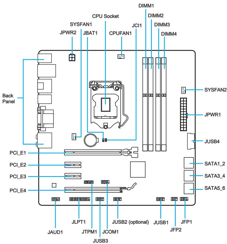
Connectors Reference Guide
| Port Name | Port Type | Page |
| Back Panel | En-7 | |
| CPU | LGA1150 CPU Socket | En-9 |
| CPUFAN1,SYSFAN1~2 | Fan Power Connectors | En-19 |
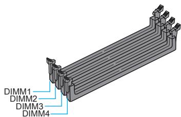
| DIMM1~4 | DDR3 Memory Slots | En-13 |
| JAUD1 | Front Panel Audio Connector | En-22 |
| JBAT1 | Clear CMOS Jumper | En-25 |
| JCI1 | Chassis Intrusion Connector | En-24 |
| JCOM1 | Serial Port Connector | En-23 |
| JFP1, JFP2 | System Panel Connectors | En-20 |
| JLPT1 | Parallel Port Connector | En-24 |
| JPWR1~2 | ATX Power Connectors | En-15 |
| JTPM1 | TPM Module Connector | En-23 |
| JUSB1~3 | USB 2.0 Expansion Connectors | En-21 |
| JUSB4 | USB 3.0 Expansion Connector | En-22 |
| PCI_E1~4 | PCIe Expansion Slots | En-16 |
| SATA1~6 | SATA Connectors | En-18 |

PS/2 Keyboard/Mouse Combo Port
A combination of PS/2® mouse/keyboard DIN connector for a PS/2® mouse/keyboard.
USB 2.0 Port
The USB 2.0 port is for attaching USB 2.0 devices such as keyboard, mouse, or other USB 2.0-compatible devices.
USB 3.0 Port
USB 3.0 port is backward-compatible with USB 2.0 devices. It supports data transfer rate up to 5 Gbit/s (SuperSpeed).

Important
In order to use USB 3.0 devices, you must connect to a USB 3.0 port. If a USB cable is used, it must be USB 3.0 compliant.
LAN Port
The standard RJ-45 LAN jack is for connecting to a Local Area Network (LAN).
| LINK/ACT LED SPEED LED | LED | LED Status | Description |
| Link/ Activity LED | Off | No link | |
| Yellow | Linked | ||
| Blinking | Data activity | ||
| Speed LED | Off | 10 Mbps connection | |
| Green | 100 Mbps connection | ||
| Orange | 1 Gbps connection |
Optical S/PDIF-Out
This S/PDIF (Sony & Philips Digital Interconnect Format) connector is provided for digital audio transmission to external speakers through an optical fiber cable.
The High-Definition Multimedia Interface (HDMI) is an all-digital audio-video interface that is capable of transmitting uncompressed streams. HDMI supports all types of TV formats, including standard, enhanced, or high-definition video, plus multi-channel digital audio on a single cable.
DisplayPort
DisplayPort is a digital display interface standard. This connector is used to connect a monitor with DisplayPort inputs.
VGA Port
The DB15-pin female connector is provided for monitor.
> DVI-D Port
The DVI-D (Digital Visual Interface- Digital) connector can be connected to a LCD monitor, or a CRT monitor with an adapter. To connect a monitor, please refer to the monitor's manual for more information.

Important
This platform supports dual-display and triple-display function.
| Extend mode (Extend the desktop to the second and third monitor) | Clone mode (Monitors have the same screen) | |
| HDMI+DisplayPort | ○ | ○ |
| HDMI+VGA | ○ | ○ |
| HDMI+DVI | ○ | ○ |
| DisplayPort+VGA | ○ | ○ |
| DisplayPort+DVI | ○ | ○ |
| VGA+DVI | ○ | ○ |
| HDMI+DisplayPort+VGA | ○ | ○ |
| HDMI+DisplayPort+DVI | ○ | ○ |
| DisplayPort+VGA+DVI | ○ | ○ |
| HDMI+VGA+DVI | ○ | ○ |
Audio Ports
These connectors are used for audio devices. The color of the jack refers to the function of the connector.
Blue-Line in: Used for connecting external audio outputting devices.
- Green- Line out: Used as a connector for speakers or headphone.
Pink-Mic: Used as a connector for a microphone.
- Black- RS-Out: Rear surround sound line out in 4/5.1/7.1 channel mode.
Orange- CS-Out: Center/ subwoofer line out in 5.1/ 7.1 channel mode.
Gray-SS-Out: Side surround sound line out in 7.1 channel mode.
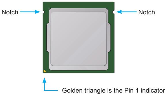
Introduction to the LGA 1150 CPU
The surface of the LGA 1150 CPU has two notches and a golden triangle to assist in correctly lining up the CPU for motherboard placement. The golden triangle is the Pin 1 indicator.

Important
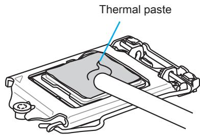
Overheating
Overheating can seriously damage the CPU and motherboard. Always make sure the cooling fans work properly to protect the CPU from overheating. Be sure to apply an even layer of thermal paste (or thermal tape) between the CPU and the heatsink to enhance heat dissipation.
Replacing the CPU
When replacing the CPU, always turn off the system's power supply and unplug the power supply's power cord to ensure the safety of the CPU.
Overclocking
This motherboard is designed to support overclocking. Before attempting to overclock, please make sure that all other system components can tolerate overclocking. Any attempt to operate beyond product specifications is not recommend. MSI does not guarantee the damages or risks caused by inadequate operation beyond product specifications.
CPU & Heatsink Installation
When installing a CPU, always remember to install a CPU heatsink. A CPU heatsink is necessary to prevent overheating and maintain system stability. Follow the steps below to ensure correct CPU and heatsink installation. Wrong installation can damage both the CPU and the motherboard.

Video Demonstration
Watch the video to learn how to install CPU & heatsink. at the address below.
http://youtu.be/bf5La099url

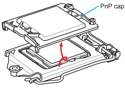
- Push the load lever down to unclip it and lift to the fully open position.
- The load plate will automatically lift up as the load lever is pushed to the fully open position.


Important
Do not touch the socket contacts or the bottom of the CPU.
- Align the notches with the socket alignment keys. Lower the CPU straight down, without tilting or sliding the CPU in the socket. Inspect the CPU to check if it is properly seated in the socket.
- Close and slide the load plate under the retention knob. Close and engage the load lever.

- When you press down the load lever the PnP cap will automatically pop up from the CPU socket. Do not discard the PnP cap. Always replace the PnP cap if the CPU is removed from the socket.
- Evenly spread a thin layer of thermal paste (or thermal tape) on the top of the CPU. This will help in heat dissipation and prevent CPU overheating.
- Locate the CPU fan connector on the motherboard.
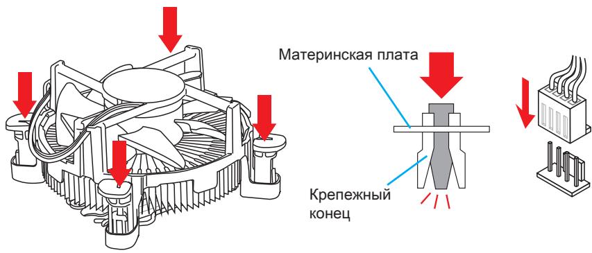
- Place the heatsink on the motherboard with the fan's cable facing towards the fan connector and the fasteners matching the holes on the motherboard.


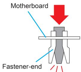
- Push down the heatsink until the four fasteners get wedged into the holes on the motherboard. Press the four fasteners down to fasten the heatsink. As each fastener locks into position a click should be heard.
- Inspect the motherboard to ensure that the fastener-ends have been properly locked in place.
- Finally, attach the CPU fan cable to the CPU fan connector on the motherboard.


Important
- Confirm that the CPU heatsink has formed a tight seal with the CPU before booting your system.
- Whenever the CPU is not installed, always protect the CPU socket pins by covering the socket with the plastic cap.
- If you purchased a separate CPU and heatsink/ cooler, Please refer to the documentation in the heatsink/ cooler package for more details about installation.
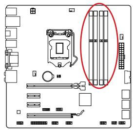
Memory
These DIMM slots are used for installing memory modules. For more information on compatible components, please visit http://www.msi.com/service/test-report/

Video Demonstration
Watch the video to learn how to install memories at the address below. http://youtu.be/76yLtJaKICQ

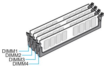
Dual-Channel mode Population Rule
In Dual-Channel mode, the memory modules can transmit and receive data with two data bus channels simultaneously. Enabling Dual-Channel mode can enhance system performance. The following illustrations explain the population rules for Dual-Channel mode.
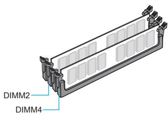


Important
- DDR3 memory modules are not interchangeable with DDR2, and the DDR3 standard is not backward compatible. Always install DDR3 memory modules in DDR3 DIMM slots.
- To ensure system stability, memory modules must be of the same type and density in Dual-Channel mode.
- Due to chipset resource usage, the system will only detect up to 31+ GB of memory (not full 32 GB) when all DIMM slots have 8GB memory modules installed.
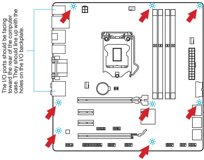
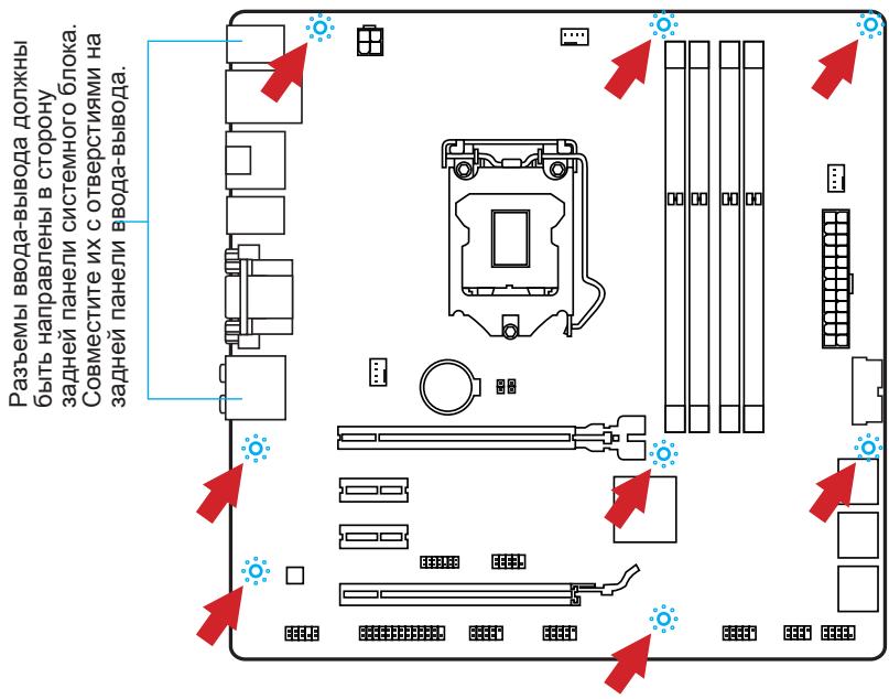
Mounting Screw Holes
When installing the motherboard, first install the necessary mounting stands required for an motherboard on the mounting plate in your computer case. If there is an I/O back plate that came with the computer case, please replace it with the I/O backplate that came with the motherboard package. The I/O backplate should snap easily into the computer case without the need for any screws. Align the mounting plate's mounting stands with the screw holes on the motherboard and secure the motherboard with the screws provided with your computer case. The locations of the screw holes on the motherboard are shown below. For more information, please refer to the manual that came with the computer case.

Important
- Install the motherboard on a flat surface free from unnecessary debris.
- To prevent damage to the motherboard, any contact between the motherboard circuitry and the computer case, except for the mounting stands, is prohibited.
- Please make sure there are no loose metal components on the motherboard or within the computer case that may cause a short circuit of the motherboard.

Video Demonstration
Watch the video to learn how to install power supply connectors. http://youtu.be/gkDYyR_8314

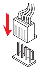
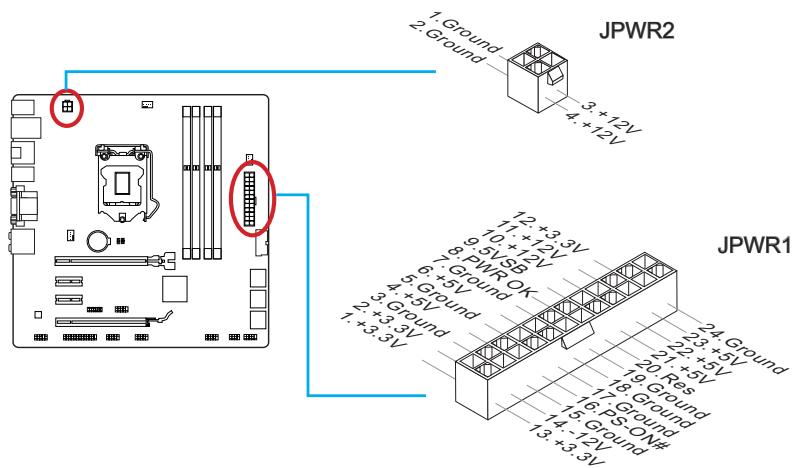
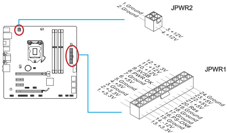
JPWR1~2:ATX Power Connectors
These connectors allow you to connect an ATX power supply. To connect the ATX power supply, align the power supply cable with the connector and firmly press the cable into the connector. If done correctly, the clip on the power cable should be hooked on the motherboard's power connector.

Important
Make sure that all the power cables are securely connected to a proper ATX power supply to ensure stable operation of the motherboard.
Expansion Slots
This motherboard contains numerous slots for expansion cards, such as discrete graphics or audio cards.
PCI_E1~4: PCIe Expansion Slots
The PCIe slot supports the PCIe interface expansion card.


Important
When adding or removing expansion cards, always turn off the power supply and unplug the power supply power cable from the power outlet. Read the expansion card's documentation to check for any necessary additional hardware or software changes.
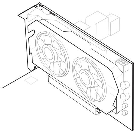
If available, this motherboard takes advantage of the CPU's integrate graphics processor, but discrete video cards can be installed by way of the motherboard's expansion slots. Adding on one or more discrete video cards will significantly boost the system's graphics performance. For best compatibility, MSI graphics cards are recommended.

Video Demonstration
Watch the video to learn how to install a graphics card on PCIe x16 slot with butterfly lock.
http://youtu.be/mG0GZpr9w_A

Single Video Card Installation
- Determine what type of expansion slot(s) the video card will use. Locate the expansion slot(s) on the motherboard. Remove any protective expansion slot covers from the computer case.
- Line up the video card on top of the expansion slot(s) with the display ports facing out of the computer case. For a single video card installation, using the PCI_E1 slot is recommended.
- Push the video card into its expansion slot(s). Depending on the expansion slot(s) used, there should be clip(s) on the expansion slot(s) that will lock in place.
- If needed, screw the edge of the graphics card to the computer case. Some video cards might require a power cable directly from the power supply.
- Please consult your video card's manual for further instructions regarding driver installation or other special settings.

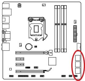
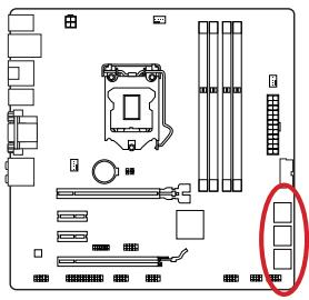
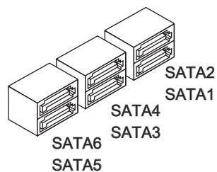
SATA1~6: SATA Connectors
This connector is a high-speed SATA interface port. Each connector can connect to one SATA device. SATA devices include disk drives (HDD), solid state drives (SSD), and optical drives (CD/DVD/Blu-Ray).

Video Demonstration
Watch the video to learn how to Install SATA HDD.
http://youtu.be/RZsMpqxythc


For Z87M-G43/H87M-G43
- SATA1~6 (6Gb/s, by Intel® Z87/H87)
For B85M-G43
- SATA1, SATA2, SATA3, SATA4 (6Gb/s, by Intel® B85)
- SATA5, SATA6 (3Gb/s, by Intel® B85)

Important
- Many SATA devices also need a power cable from the power supply. Such devices include disk drives (HDD), solid state drives (SSD), and optical drives (CD / DVD / Blu-Ray). Please refer to the device's manual for further information.
- Many computer cases also require that large SATA devices, such as HDDs, SSDs, and optical drives, be screwed down into the case. Refer to the manual that came with your computer case or your SATA device for further installation instructions.
- Please do not fold the SATA cable at a 90-degree angle. Data loss may result during transmission otherwise.
- SATA cables have identical plugs on either sides of the cable. However, it is recommended that the flat connector be connected to the motherboard for space saving purposes.
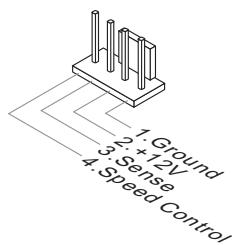
CPUFAN1,SYSFAN1~2:FanPower Connectors
The fan power connectors support system cooling fans with +12V. If the motherboard has a System Hardware Monitor chipset on-board, you must use a specially designed fan with a speed sensor to take advantage of the CPU fan control. Remember to connect all system fans. Some system fans may not connect to the motherboard and will instead connect to the power supply directly. A system fan can be plugged into any available system fan connector.


Important
- Please refer to your processor's official website or consult your vendor to find recommended CPU heatsink.
- These connectors support Smart Fan Control with liner mode. The Command Center utility can be installed to automatically control the fan speeds according to the CPU's and system's temperature.
- If there are not enough ports on the motherboard to connect all system fans, adapters are available to connect a fan directly to a power supply.
- Before first boot up, ensure that there are no cables impeding any fan blades.
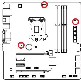
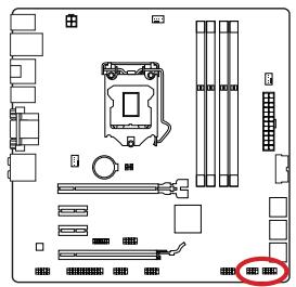
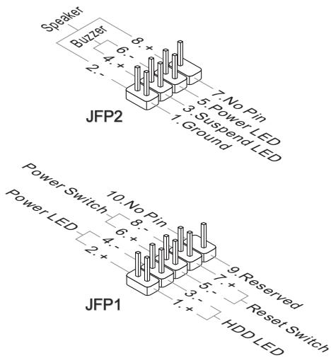
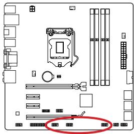
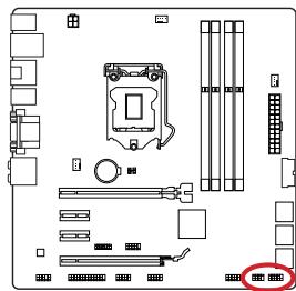
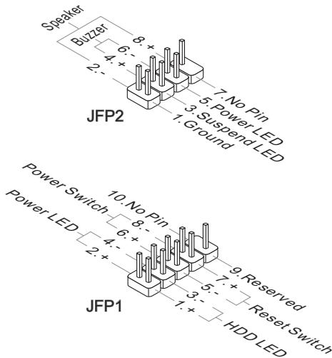
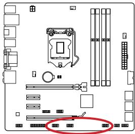
JFP1, JFP2: System Panel Connectors
These connectors connect to the front panel switches and LEDs. The JFP1 connector is compliant with the Intel® Front Panel I/O Connectivity Design Guide. When installing the front panel connectors, please use the optional M-Connector to simplify installation. Plug all the wires from the computer case into the M-Connector and then plug the M-Connector into the motherboard.

Video Demonstration
Watch the video to learn how to Install front panel connectors. http://youtu.be/DPELldVNZUI


Important
- On the connectors coming from the case, pins marked by small triangles are positive wires. Please use the diagrams above and the writing on the optional M-Connectors to determine correct connector orientation and placement.
- The majority of the computer case's front panel connectors will primarily be plugged into JFP1.
JUSB1~3: USB 2.0 Expansion Connectors
This connector is designed for connecting high-speed USB peripherals such as USB HDDs, digital cameras, MP3 players, printers, modems, and many others.

The JUSB2 connector is optional.
The JUSB1 (red mark) connector supports MSI's new SuperCharger technology which provides quicker USB charging of your cellular phone or other USB-powered devices. To enable this feature, please install the MSI SuperCharger application on your computer. When the SuperCharger application is turned on, the JUSB1 connector will convert data channels to extra power channels to quickly charge your connected device. Please note that when the SuperCharger application is turned on, data transmission and synchronization over the JUSB1 connector will not function. To enable the JUSB1 connector to function as a normal USB 2.0 connector, please turn off the SuperCharger application. When the computer is in stand-by or hibernation mode (S3/ S4/ S5) SuperCharger mode will automatically be enabled.

Important
- Note that the VCC and GND pins must be connected correctly to avoid possible damage.
- Please only connect one device per USB port to ensure stable charging.
- SuperCharger Technology is only available on select MSl motherboard models. Please refer to the MSl website to check if your motherboard has SuperCharger technology.
- For iPad, JUSB1 (red mark) can still charge iPad in S3, S4, S5 state.
- We recommend that don't disconnect the device when you charge it in S1 state.
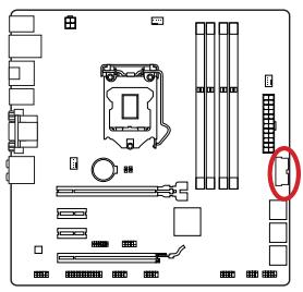
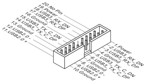
JUSB4: USB 3.0 Expansion Connector
The USB 3.0 port is backwards compatible with USB 2.0 devices. It supports data transfer rates up to 5Gbits/s (SuperSpeed).


Important
- Note that the VCC and GND pins must be connected correctly to avoid possible damage.
- To use a USB 3.0 device, you must connect the device to a USB 3.0 port through an optional USB 3.0 compliant cable.
JAUD1: Front Panel Audio Connector
This connector allows you to connect the front audio panel located on your computer case. This connector is compliant with the Intel® Front Panel I/O Connectivity Design Guide.


JTPM1: TPM Module Connector
This connector connects to a TPM (Trusted Platform Module). Please refer to the TPM security platform manual for more details and usages.
JCOM1: Serial Port Connector
This connector is a 16550A high speed communication port that sends/receives 16 bytes FIFOs. You can attach a serial device.

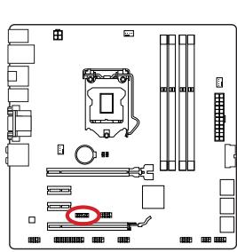
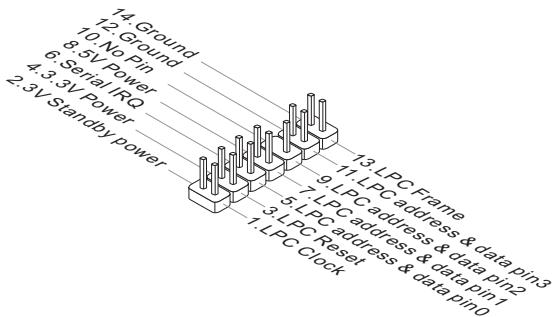
JLPT1: Parallel Port Connector
This connector is used to connect an optional parallel port bracket. The parallel port is a standard printer port that supports Enhanced Parallel Port (EPP) and Extended Capabilities Parallel Port (ECP) mode.

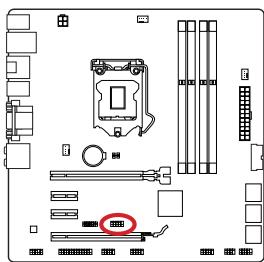
JCI1: Chassis Intrusion Connector
This connector connects to the chassis intrusion switch cable. If the computer case is opened, the chassis intrusion mechanism will be activated. The system will record this intrusion and a warning message will flash on screen. To clear the warning, you must enter the BIOS utility and clear the record.


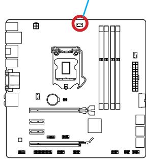
JBAT1: Clear CMOS Jumper
There is CMOS RAM onboard that is external powered from a battery located on the motherboard to save system configuration data. With the CMOS RAM, the system can automatically boot into the operating system (OS) every time it is turned on. If you want to clear the system configuration, set the jumpers to clear the CMOS RAM.


Keep Data

Clear Data

Important
You can clear the CMOS RAM by shorting this jumper while the system is off. Afterwards, open the jumper. Do not clear the CMOS RAM while the system is on because it will damage the motherboard.
After you install the operating system you will need to install drivers to maximize the performance of the new computer you just built. MSI motherboard comes with a Driver Disc. Drivers allow the computer to utilize your motherboard more efficiently and take advantage of any special features we provide.
You can protect your computer from viruses by installing the bundled security program. The bundle also includes a variety of powerful and creative utilities.
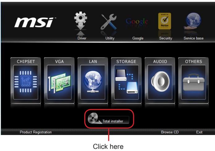
Total Installer
Total Installer is very easy to use and does a great job of finding necessary drivers. Please follow the steps below to install drivers and utilities for your new computer.
- Insert MSI Driver Disc into the optical drive. The setup screen will automatically appear if autorun is enabled in OS.
- Click Total Installer. A popup dialogue will appear listing all necessary drivers.
- Select all checkbox on driver listing dialog.
- Click Install button.
- The software installation will then be in progress, after it has finished it will prompt you to restart.
- Click OK button to finish.
- Restart your computer.
You can also use the same method to install the utilities.
BIOS Setup
CLICK BIOS is developed by MSI that provides a graphical user interface for setting parameters of BIOS by using the mouse and the keyboard.
With the CLICK BIOS, users can change BIOS settings, monitor CPU temperature, select the boot device priority and view system information such as the CPU name, DRAM capacity, the OS version and the BIOS version. Users can import and export parameters data for backup or sharing with friends.
Entering BIOS Setup
Power on the computer and the system will start the Power On Self Test (POST) process. When the message below appears on the screen, please key to enter BIOS:
Press DEL key to enter Setup Menu, F11 to enter Boot Menu
If the message disappears before you respond and you still need to enter BIOS, restart the system by turning the computer OFF then back ON or pressing the RESET button. You may also restart the system by simultaneously pressing <Ctrl> , <Alt> , and <Delete> keys.
MSI additionally provides two methods to enter the BIOS setup. You can click the "GO2BIOS" tab on "MSI Fast Boot" utility screen or press the physical "GO2BIOS" button (optional) on the motherboard to enable the system going to BIOS setup directly at next boot.


Important
- Please be sure to install the "MSI Fast Boot" utility before using it to enter the BIOS setup.
- The items under each BIOS category described in this chapter are under continuous update for better system performance. Therefore, the description may be slightly different from the latest BIOS and should be held for reference only.
Overview
After entering BIOS, the following screen is displayed.
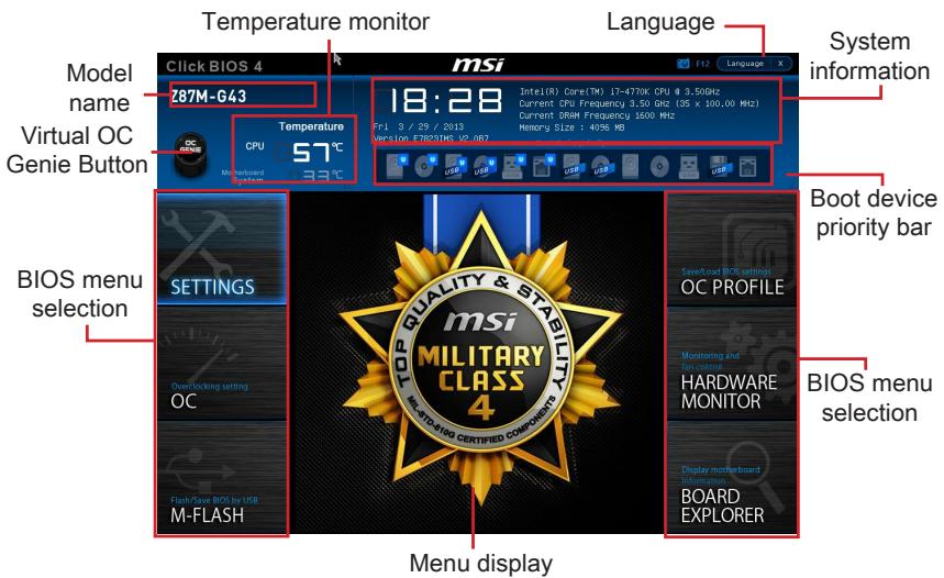
Temperature monitor
Shows the temperatures of the processor and the motherboard.
Language
Allows you to select the language of the BIOS setup.
System information
Shows the time, date, CPU name, CPU frequency, DRAM frequency, DRAM capacity and the BIOS version.
BIOS menu selection
The following options are available:
- SETTINGS - Uses this menu to specify the parameters for chipset and boot devices.
- OC - This menu contains the frequency and voltage adjustments. Increasing the frequency can get better performance, however high frequency and heat can cause instability, we do not recommend general users to overclock.
- M-FLASH - This menu provides the way to update BIOS with a USB flash disk.
OC PROFILE -This menu is used to set various overclocking profiles. - HARDWARE MONITOR - This menu is used to set the speeds of fans and monitor voltages of system.
BOARD EXPLORER - It will provide the information of the installed devices on the motherboard.
Boot device priority bar
You can move the device icons to change the boot priority.

High priority Low priority
Menu display
This area provides BIOS settings and information to be configured.
Virtual OC Genie Button
Enables or disables the OC Genie function by clicking on this button. When enabled, this button will be light. Enabling OC Genie function can automatically overclock with MSI optimized overclocking profile.
Model Name
Shows the model name of motherboard.
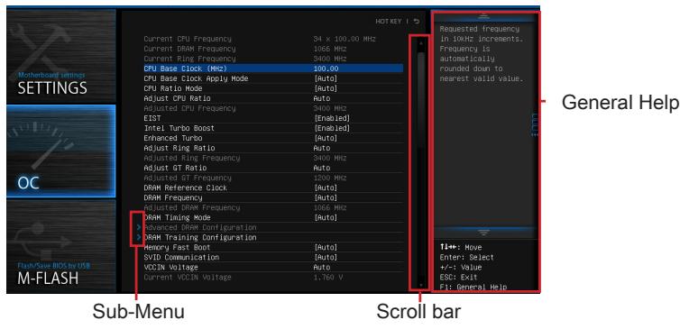
Sub-menu
If you find a point symbol to the left of certain items, that means a sub-menu can be launched for additional options. You can use the arrow keys or mouse to highlight the item and press
Scroll bar
Slide the scroll bar or use the arrow keys to display the other items that are available on the "menu display" area.
General Help
The General Help displays a brief description to assist you in grasping the selected item.
Operation
You can control BIOS settings with the mouse and the keyboard. The following table lists and describes the hot keys and the mouse operations.
| Hot key | Mouse | Description |
| <↑↓→←> | Move the cursor | Select Item |
| <Enter> | Click/ Double-click the left button | Select Icon/ Field |
| <Esc> | Click the right button | Jump to the Exit menu or return to the previous from a submenu |
| <++> | Click the right button | Increase the numeric value or make changes |
| <-> | Decrease the numeric value or make changes | |
| <F1> | General Help | |
| <F4> | CPU Specifications | |
| <F5> | Enter Memory-Z | |
| <F6> | Load optimized defaults | |
| <F8> | OC Profile Load From USB | |
| <F9> | OC Profile Save to USB | |
| <F10> | Save Change and Reset | |
| <F12> | Save a screenshot to a FAT/FAT32 USB drive |
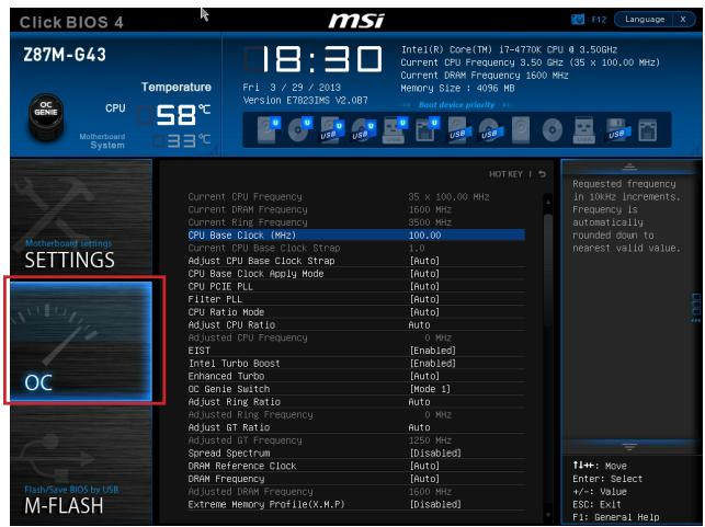
OC Menu
This menu is for advanced users who want to overclock the mainboard.

Important
- Overclocking your PC manually is only recommended for advanced users.
- Overclocking is not guaranteed, and if done improperly, can void your warranty or severely damage your hardware.
- If you are unfamiliar with overclocking, we advise you to use OC Genie for easy overclocking.
Current CPU/ DRAM/ Ring Frequency
These items show the current frequencies of installed CPU, Memory and Ring. Read-only.
CPU Base Clock (MHz) [Default]
Sets the CPU Base clock. You may overclock the CPU by adjusting this value. Please note that overclocking behavior and stability is not guaranteed. This item appears when the installed processor supports this function.
Current CPU Base Clock Strip (for Z87M-G43)
Shows the current CPU Base Clock Strap. Read only. This item can only be changed if the processor supports this function.
Adjust CPU Base Clock Strap [Auto]
Sets the CPU Base Clock Strap. You may overclock the CPU Base Clock by adjusting this value. Please note that overclocking behavior and stability is not guaranteed. This item can only be changed if the processor supports this function. If set to "Auto", BIOS will configure this setting automatically. [Options: Auto, 1.00, 1.25, 1.67]
CPU Base Clock Apply Mode [Auto]
Sets the applying mode for adjusted CPU base clock.
[Auto] This setting will be configured automatically by BIOS.
[Next Boot] CPU will run the adjusted CPU base clock after reboot.
[Immediate] CPU runs the adjusted CPU base clock immediately.
CPU Ratio Mode [Auto]
Selects the CPU Ratio operating mode.
[Auto] This setting will be configured automatically by BIOS.
[Fixed Mode] Fits the CPU ratio.
[Dynamic Mode] CPU ratio will be changed dynamically according to the CPU loading.
Adjust CPU Ratio [Auto]
Sets the CPU ratio that is used to determine CPU clock speed. This item can only be changed if the processor supports this function.
Adjusted CPU Frequency
Shows the adjusted CPU frequency. Read-only.
EIST [Enabled]
Enables or disables the Enhanced Intel® SpeedStep Technology.
Intel Turbo Boost [Enabled]
Enables or disables the Intel® Turbo Boost. This item appears when the installed CPU supports this function.
[Enabled] Enables this function to boost CPU performance automatically above rated specifications when system request the highest performance state.
[Disabled] Disables this function.
Enhanced Turbo [Auto]
Enables or disables Enhanced Turbo function for all CPU cores to boost CPU performance.
[Auto] This setting will be configured automatically by BIOS.
[Enabled] All CPU cores would be increased to maximum turbo ratio.
[Disabled] Disables this function.
OC Genie Switch [Gear1]
Selects a kind of overclocking profiles for OC Genie Function. This item appears when "OC Genie Function Control" sets to [By BIOS Options].
[Gear1] Enables Gear1 overclocking profile for overclocking.
[Gear2] Enables Gear2 overclocking profile for extreme overclocking.
![MSI B85M-G43 - CPU Base Clock Apply Mode [Auto] - 1](/content/2019/06/199141/images/8ed6efbfcabed1cebac49cf9f3286f1233429ffd5cef4d15c43c1410e891f9a1.jpg)
Important
-
We recommend that you do not to make any modification in OC menu and do not to load defaults after enabling the OC Genie function.
-
Updating BIOS or clearing CMOS is not allowed in OC Genie mode, and it may cause OC Genie function fail or other effect.
Adjust Ring Ratio [Auto]
Sets the ring ratio. The valid value range depends on the installed CPU.
Adjusted Ring Frequency
Shows the adjusted Ring frequency. Read-only.
Adjust GT Ratio [Auto]
Sets the integrated graphics ratio. The valid value range depends on the installed CPU.
Adjusted GT Frequency
Shows the adjusted integrated graphics frequency. Read-only.
DRAM Reference Clock [Auto]
Sets the DRAM reference clock. The valid value range depends on the installed CPU. This item appears when a CPU that supports this adjustment is installed.
DRAM Frequency [Auto]
Sets the DRAM frequency. Please note the overclocking behavior is not guaranteed.
Adjusted DRAM Frequency
Shows the adjusted DRAM frequency. Read-only.
Extreme Memory Profile (X.M.P) [Disabled]
X.M.P. (Extreme Memory Profile) is the overclocking technology by memory module. This item will be available when you install the memory modules that support X.M.P. technology.
[Disabled] Disables this function.
[Profile 1] Uses profile1 over-clocking settings of installed XMP memory module.
[Profile 2] Uses profile2 over-clocking settings of installed XMP memory module.
DRAM Timing Mode [Auto]
Selects the memory timing mode.
[Auto] DRAM timings will be determined based on SPD (Serial Presence Detect) of installed memory modules.
[Link] Allows user to configure the DRAM timing manually for all memory channel.
[UnLink] Allows user to configure the DRAM timing manually for respective memory channel.
Advanced DRAM Configuration
Press
DRAM Training Configuration
Press
Memory Fast Boot [Auto]
Enables or disables the initiation and training for memory every booting.
[Auto] This setting will be configured automatically by BIOS.
[Enabled] Memory will completely imitate the archive of first initiation and first training. After that, the memory will not be initialized and trained when booting to accelerate the system booting time.
[Disabled] The memory will be initialized and trained every booting.
SVID Communication [Auto]
Enables or disables SVID (Serial Voltage Identification) support.
[Auto] This setting will be configured automatically by BIOS.
[Enabled] PWM phase will be changed dynamically according to the CPU SVID (Serial Voltage Identification).
[Disabled] Disables SVID (Serial Voltage Identification) support.
VCCIN Voltage [Auto]
Sets the CPU input voltage. The CPU input voltage is the CPU power source that is shared with components of the CPU.
Current VCCIN Voltage
Shows current CPU VCCIN voltage. Read-only.
- CPU Core Voltage Mode/ CPU Ring Voltage Mode/ CPU GT Voltage Mode [Auto]
Selects the control modes for these voltages.
[Auto] This setting will be configured automatically by BIOS.
[Adaptive Mode] Sets adaptive voltages automatically for optimizing the system performance.
[Override Mode] Allows you to set these voltages manually.
CPU Core Voltage/ CPU Ring Voltage/ CPU GT Voltage [Auto]
Sets these voltages. If set to "Auto", BIOS will set these voltages automatically or you can set it manually.
- CPU Core Voltage Offset Mode/ CPU Ring Voltage Offset Mode/ CPU GT Voltage Offset Mode/ CPU SA Voltage Offset Mode/ CPU IO Analog Voltage Offset Mode/ CPU IO Digital Voltage Offset Mode [Auto]
Selects the voltage offset modes.
[Auto] This setting will be configured automatically by BIOS.
[+] Allows you to set the positive offset voltage.
[-] Allows you to set the negative offset voltage.
- CPU Core Voltage Offset/ CPU Ring Voltage Offset/ CPU GT Voltage Offset/ CPU SA Voltage Offset/ CPU IO Analog Voltage Offset/ CPU IO Digital Voltage Offset [Auto]
Set the offset values for these voltages.
Current CPU Core Voltage/ Current CPU Ring Voltage/ Current CPU GT Voltage/ Current CPU SA Voltage/ Current CPU IO Digital Voltage
Show the current voltages. Read-only.
Internal VR OVP OCP Protection [Auto]
Enables or disables the over-voltage protection and over-current protection for CPU internal VR (Voltage Regulator).
[Auto] This setting will be configured automatically by BIOS.
[Enabled] Sets the voltage limit on the CPU internal VR for over-voltage protection and over-current protection.
[Disabled] Disables this function for overclocking.
Internal VR Efficiency Management [Auto]
Enables or disables the CPU internal VR efficiency management.
[Auto] This setting will be configured automatically by BIOS.
[Enabled] Enables the VR efficiency management for power-saving control.
[Disabled] Disables this function.
DRAM Voltage [Auto]
Sets the memory voltage. If set to "Auto", BIOS will set memory voltage automatically or you can set it manually.
Current DRAM Voltage
Shows current memory voltage. Read only.
CPU Memory Changed Detect [Enabled]
Enables or disables the system to issue a warning message during boot when the CPU or memory has been replaced.
[Enabled] The system will issue a warning message during boot and then needs to load the default settings for new devices.
[Disabled] Disables this function and keeps the current BIOS settings.
Spread Spectrum
This function reduces the EMI (Electromagnetic Interference) generated by modulating clock generator pulses.
[Enabled] Enables the spread spectrum function to reduce the EMI (Electromagnetic Interference) problem.
[Disabled] Enhances the overclocking ability of CPU Base clock.

Important
- If you do not have any EMI problem, leave the setting at [Disabled] for optimal system stability and performance. But if you are plagued by EMI, select the value of Spread Spectrum for EMI reduction.
- The greater the Spread Spectrum value is, the greater the EMI is reduced, and the system will become less stable. For the most suitable Spread Spectrum value, please consult your local EMI regulation.
- Remember to disable Spread Spectrum if you are overclocking because even a slight jitter can introduce a temporary boost in clock speed which may just cause your overclocked processor to lock up.
CPU Specifications
Press
CPU Technology Support
Press
MEMORY-Z
Press
> DIMM1~4 Memory SPD
Press
CPU Features
Press
Hyper-Threading Technology [Enabled]
The processor uses Hyper-Threading technology to increase transaction rates and reduces end-user response times. Intel Hyper-Threading technology treats the multi cores inside the processor as multi logical processors that can execute instructions simultaneously. In this way, the system performance is highly improved.
[Enable] Enables Intel Hyper-Threading technology.
[Disabled] Disables this item if the system does not support HT function.
Active Processor Cores [All]
This item allows you to select the number of active processor cores.
Limit CPUID Maximum [Disabled]
Enables or disables the extended CPUID value.
[Enabled] BIOS will limit the maximum CPUID input value to circumvent boot problems with older operating system that do not support the processor with extended CPUID value.
[Disabled] Use the actual maximum CPUID input value.
Execute Disable Bit [Enabled]
Intel's Execute Disable Bit functionality can prevent certain classes of malicious "buffer overflow" attacks where worms attempt to execute code to damage the system. It is recommended that keeps this item enabled always.
[Enabled] Enables NO-Execution protection to prevent the malicious attacks and worms.
[Disabled] Disables this function.
> Intel Virtualization Tech [Enabled]
Enables or disables Intel Virtualization technology.
[Enabled] Enables Intel Virtualization technology and allows a platform to run multiple operating systems in independent partitions. The system can function as multiple systems virtually.
[Disabled] Disables this function.
Hardware Prefetcher [Enabled]
Enables or disables the hardware prefetcher (MLC Streamer prefetcher).
[Enabled] Allows the hardware prefetcher to automatically pre-drop data and instructions into L2 cache from memory for tuning the CPU performance.
[Disabled] Disables the hardware prefetcher.
Adjacent Cache Line prefetch [Enabled]
Enables or disables the CPU hardware prefetcher (MLC Spatial prefetcher).
[Enabled] Enables adjacent cache line prefetching for reducing the cache latency time and tuning the performance to the specific application.
[Disabled] Enables the requested cache line only.
CPU AES Instructions [Enabled]
Enables or disables the CPU AES (Advanced Encryption Standard-New Instructions) support. This item appears when a CPU supports this function.
[Enabled] Enables Intel AES support.
[Disabled] Disables Intel AES support.
Intel Adaptive Thermal Monitor [Enabled]
Enables or disables the Intel adaptive thermal monitor function to protect the CPU from overheating.
[Enabled] Throttles down the CPU core clock speed when the CPU is over the adaptive temperature.
[Disabled] Disables this function.
Intel C-State [Auto]
C-state is a processor power management technology defined by ACPI.
[Auto] This setting will be configured automatically by BIOS.
[Enabled] Detects the idle state of system and reduce CPU power consumption accordingly.
[Disabled] Disable this function.
C1E Support [Disabled]
Enables or disables the C1E function for power-saving in halt state. This item appears when "Intel C-State" is enabled.
[Enabled] Enables C1E function to reduce the CPU frequency and voltage for power-saving in halt state.
[Disabled] Disables this function.
Package C State limit [Auto]
This item allows you to select a CPU C-state mode for power-saving when system is idle. This item appears when "Intel C-State" is enabled.
[Auto] This setting will be configured automatically by BIOS.
[C0~C7s] The power-saving level from high to low is C7s, C7, C6, C3, C2, then C0.
[No limit] No C-state limit for CPU.
LakeTiny Feature [Disabled]
Enables or disables Intel Lake Tiny feature with iRST for SSD. This item appears when a installed CPU supports this function and "Intel C-State" is enabled.
[Enabled] Enhance the dynamic IO load adjusted performance for accelerating the SSD speed.
[Disabled] Disables this feature.
Note: The following items will appear when "Intel Turbo Boost" is enabled.
Long Duration Power Limit (W) [Auto]
Sets the long duration TDP power limit for CPU in Turbo Boost mode.
Long Duration Maintained (s) [Auto]
Sets the maintaining time for "Long duration power Limit(W)".
Short Duration Power Limit (W) [Auto]
Sets the short duration TDP power limit for CPU in Turbo Boost mode.
CPU Current limit (A) [Auto]
Sets maximum current limit of CPU package in Turbo Boost mode. When the current is over the specified limit value, the CPU will automatically reduce the core frequency for reducing the current.
1/2/3/4-Core Ratio Limit [Auto]
These items only appear when a CPU that support this function is installed. These items allow you to set the CPU ratios for different number of active cores in turbo boost mode. These items appear when the installed processor supports this function.
JPWR1~2:ATX Stromanschlüsse
CPUFAN1,SYSFAN1~2:Stromanschlüsse fur Lufter
JFP1, JFP2: Frontpanel Anschlüsse
Current CPU/ DRAM/ Ring Frequency
Adjust CPU Base Clock Strap [Auto]
Adjust CPU Ratio [Auto]
Adjusted CPU Frequency
Adjusted GT Frequency
Adjusted DRAM Frequency
Current VCCIN Voltage
Internal VR Efficiency Management [Auto]
Current DRAM Voltage
CPU Technology Support
> Adjacent Cache Line prefetch [Enabled]
Intel C-State [Auto]
Long Duration Power Limit (W) [Auto]
Long Duration Maintained (s) [Auto]
CPU Current limit (A) [Auto]
Current CPU/ DRAM/ Ring Frequency
Current CPU Base Clock Strip (for Z87M-G43)
Adjust CPU Base Clock Strap [Auto]
[Fixed Mode] Fixer le ratio CPU.
Adjust CPU Ratio [Auto]
Adjusted CPU Frequency
Adjust Ring Ratio [Auto]
Active ou désactive le support SVID (Serial Voltage Identification).
[Disabled] Désactive le support SVID (Serial Voltage Identification.
VCCIN Voltage [Auto]
Current VCCIN Voltage
CPU Core Voltage/ CPU Ring Voltage/ CPU GT Voltage [Auto]
Current CPU Core Voltage/ Current CPU Ring Voltage/ Current CPU GT Voltage/ Current CPU SA Voltage/ Current CPU IO Digital Voltage
Internal VR Efficiency Management [Auto]
Current DRAM Voltage
CPU Technology Support
> Adjacent Cache Line Prefetch [Enabled]
Active ou désactive le prefetcher matériel CPU (MLC Spatial prefetcher).
CPU AES Instructions [Enabled]
[Enabled] Active le support Intel AES.
[Disabled] Désactive le support Intel AES.
Intel Adaptive Thermal Monitor [Enabled]
Intel C-State [Auto]
Long Duration Power Limit (W) [Auto]
Long Duration Maintained (s) [Auto]
Short Duration Power Limit (W) [Auto]
CPU Current limit (A) [Auto]
YcTaHOBka LII paIaTOpa
Pn yctahOBke npoceccoopa o63aTeIbHO yCTAHOBtpe padnatop LPi.PaHATOP LII npedynpexkdaet neperepaBHeNIO bcneuBaET cTabNbHoCTb pa60Tb CNTeMbI. HnKe npedctabIeHb I NcTpyKUIN IO npaBnIbHOy YCTAHOBke npoceccopa n paHaIATOP LII.HenpaBnIbHaY cTaHOBKa pInBOIDN K BbIXOy n3 cTpor npoceccopa n MaTePHNckO PnAtbl.

Buiero Demohetpalu
CmToPnTe BnDeo,HTO6bI y3HaTb KaK yCTaHOBuTb npoueccop N Kynep: http://youtu.be/bf5La099url

He Tporai Te KOthakTbI pa3bema IJIN HnXkHe Yactn npoceccopa.
- BbipabHnTe BbIeMKn Ha npoceccope K KJIouamn COBMeueHna CoKeTe.
Onyctnte npoecccop BHN3, 6e3 haknoha nIN DBNKeHnna npoecccopa B COkeTe.
PpOBepbTe HndexKHOCTb yCTaHOBKn npoecccopa B COkeTe. - 3aKpoIte n CdbuHbTe npKmHHy pnaCTnHy nop pyuKy ykepKaHn. 3akpoIte n 3aCenIte pbUarФKKcaun.

- Пи нахати на рьчаг Фнcaци 3ацптая крblшka abTomatчески ВсICКOTИЗ rHeZda поцeccopa. He bIbpaCbIaBaiTe 3aцNTHyO крblshky. Bcerda yctahablnBaIte 3aцNTHyIO крblshky, ecIn поцeccop BbIHMaTcN 3СOKeTa.
- PaBHOmePno HAnecnte ToHkIn CNoI TepMOnaCTbI (NJIIN TepMOJeHTy) Ha BepXHIOKpbIshky npOceccopa. 3To nO3BOJNT yBeJIuHTb TeIIpOpepaUy I npEdoTbPaTITpeperpeB npOceccopa.

- HauTe pa3bem IJIy NODKJIIOUeHnBEHTINJATOPaIHa MaTePNHcOJI Pnate.
- YctaHOBInTe KUneR Ha MaTePnHcKyo IJIaTy, HAnpABuB erO Ka6eJb B CToPOHy pa3bema dIra NODKNIOUHeHr BEHTINlAToPA.
Pa3bem IOKnIoueHn
BENTNIJTOPA
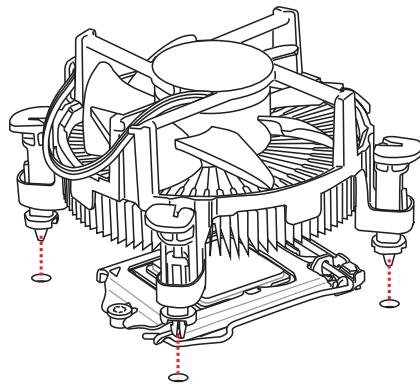
- Haxmte Ha paDnatop cbepx TaK, YTO6bI 3aKePnITb YeTbIpe 3aUeKN B OTBepCTnX Ha MaTePHNcKo PnATE. Haxmte Ha 3aUeJIKn DnIg 3aKePnJIeHnBEHTNJrTopa. KaKdbI n3 3aUeJOK fHKCnpyETc C xapAKTePnhIM UeJIYkOM.
- Ocmotpnte MaTePNHckyu nIaTy u onpeJeNte npabnIbHocTb 3akpeJIneHn 3axIMOB.
- И, наточ, полочи Кабелы вентлаятора поз ECCOPA К разьему вентлаятора на сисимонпатe.

BHIMAHUE
- Пара вклоченemсnteMbI npOBepbTe rePMeTnUHOCtB coeDInHeHnMexdY npouceccopom n paDnATOpom.
- Ecnn npoceccop He yctaHOBJIeN, Bcerda 3aunuauTe KOHTaKTbI npoceccopHorO COKeta NpactIKOBOI KpbIkoJ.
- Ecnn Bbl npnoobpenn OTdelenbNo npoceccop n npoceccpnkyep, noippo6hoe onicahne yctahOBKn CM. B Dokymehntaunn B daHHOMy Kynepy.
Pa3bEmbl DIMM npedna3HaueHb IJy yctaHOBKn MoUyIe namrTn. PoOp6Hyu INΦopMaζH O COBmecTlMbIX KOMNoHEHTax cM. Ha caIte http://www.msi.com/ service/test-report/


BvHoe DEmohetpaY
CMOTPNE BnDeo,HTObI y3HaTb KaK yCTaHOBtB nAmrTb NO yKa3aHHOMy aDpecy.
http://youtu.be/76yLtJaKICQ

IpaBnla 3aOpJIHeHnra He3d npn nCpOJIb3OBaHn nDByXkaHaJIbHOpeKIma Dual-Channel
В двухканьном ржиме мodyлпамгт одноberеменno пeredаыт b n polуатдадныпдвум каналamшиbl. Влоченье двухканьногоржимa Dual-Channel moxet noвсintb npoIN3BOJNTeJIbHOCTB cnsTeMbI. Ha pucyнхax nhxe pokazahnbnpabuHa 3anONHeHn rHe3d namrtn npin nCpOJIb3OBAHm nDvYkaHaNBOrpejzma Dual-Channel.


BHTMAHNE
- Moулл DD3 He b3aunmo3aemeHЯemb C Moуллm DDR2, ctaHapr DDR3 He nOДержИBaet o6paTHyIO COBMeCTUMocTb. Moулл NaMaTn DDR3 cneJyET yCtahabNbaTb B pa3bEmbl DDR3 DIMM.
- Дя обесеньяставиьни рабы сисимы в дыхсаньnom peжime yctанавл�аюс.TMOули памгтпдунakoboro TИпа и EMKOCTN.
B CBA3N CO CNEUΦKo NcNoJIb3OBAHnI pecyPCOB MmKpOnpoCeccopa, npu yCTaHOBKe MOdyNei namrtn EMcKocTbIO 8 ΓB BO Bce pa3bEmbl DIMM cncTeMHa namrTo ONpeJeTae TOnbKO Do 31+ ΓB (HeNoJIbIe 32 ΓB).
Дя установки материнсков плatable на мостахно плATE сисмHorо 6лoka chача на установпгеонбхODIMьгь установочьгь стой.Еси в komплент NOCTавки сисмHorо 6лoka BXODIT 3адня панел bвда-bыюda,заменite ee 3адня панелю Bвда-Bыюda, кOTOPЯ NOCTabIЯТССС MATEPINHСКО ПЛATOM. 3адня панель bвда-Bыюда 6e3 trya установльbaeTCB CSCTMHOM 6LOKE komпьIoTeра 6e3 npimehenra BINTOB.COBmecTte yстановочьгь стой MONTAXHONПЛATbC OTBepCTNIMNoID uystahoBOUHbE BVHTbHa MATEPINHСКО ПЛATEи 3akpenITE mATEPHNCKYIO pIATy BVNTAMN, KOTOpbie NOCTaBJIYOTcB MECTe C CSCTemblm 6LOKOM.Hnke nokazao paocnoLOXeHne OTBepCTN IOd y cStahOBOuHbIe BVHTb.ДOnonHInTeIbHyIO INΦopMaцИ CM.BpyKOBoDCTBE K CSCTEMHomy 6lOKy.

BhIMaHHe
- Плоскту матернскую пату на ровбу и чicitую поьерхонст.
Bo n36eXaHHe NOBpeXdEHH MaTePHNcKo PnAtpbI, 3akpenPJIte 3neKTPoHHbIe KOMHOHeHTbHa yCTaHOBOUHbIX CToiKaX, n36eRa Ix COpNIKOCHOBHeHc C NCTeMHbIM 6lOKOM. - Поверьтей Наджноctь Креленя BCex Металл用电х KOMnoHeTOB Ha MaTePNHcKo ПлATE ИИВуТРССТЕМНОв 6лoka. He3akpeIeHbIe DeTaII MOrTy ПиВЕСТК KOKOTKOMY 3amblaKaHnIO MaTePNHcKO ПлАТы.

Buiyeo,DeMoHepaH
CMOTPTE BnDcEo,HTO6bI y3HaTb KaK yCTaHOBtbpa3bEm NITaHn.
http://youtu.be/gkDYr_83l4

JPWR1~2:Pa3bembl nHTaHnA TX
3Tn pa3bembl npedHa3hauehblIy nOdkluoyehna pa3bema nItaHNA ATX.ДЯ nOdkluoyehna ATX pa3bema nItaHNA COBmecTne Ka6JIb nItaHNA c pa3bEmOM npOchu 3akpennte erO.Ipn npabInbHom BblOnHeHHn nOdkluoyehna 3aueKka Ha ka6ene nItaHNA 3akpenlareTCB CINOBom pa3beme MaTePHNcKoI PnAbl.

BhIMaHHe
Дя obecneuehenna CTaBnIbHOn pa6oTbI cncTeMHO nIpaTbI npOBepbTe HaedKHOCTb IpoKnIOUeHnBcex KaBeNei NtAHnI K COOTBeTcTByOuEmy bNOKy NtAHnI A TX.
BnIeO/YcTaHOBKa DnCKpeTHoN BnIeOKapTbI
IyoMOnuHaHIO,DaHHaIIaTaIcNoB3yEt rpaΦnueckoe JdoPO INTePnpoBaHHO BCPU,HO BbI TaK Je MoXeTe 3NaHTeNbHO NObICNT rpaΦnueckyo npOn3BOUInTeNbHOCTb CnCTeMbI,NyTeM Do6abJeHne ODoH NIN HeCKOJIbKINx DnCKpeTHbIX BnDEOKapT B CnOTbl paCnupenH.NIpyNJuWe COBMeCTmOCtne peKOMeHdyETc IcNoJb3OBaTB rpaΦnueckne KapTbI MSl.

Buae O DeMoHepaH
CMOTNE BINO, uTObI y3HaTb KaK yCTaHOBnTB BInDeOkaPty Ha CNOTe PCIe x16 c 3amKom.
http://youtu.be/mG0GZpr9w_A

YcTaHOBka OJHO BnDEOkapTbI
- OnpeDenite TnCnTpaacunpeHn, KOTOpb nCnObl3yeTc BnDEOKapToi. HauInTe COoTBetCTBlyUOni CnOt(bI) Ha MaTePHNckO nnate. BbHbTe 3aunTHyo KpbuKy cNoTaOB) paacunpeHn n3 Kopnyca cnCTemHoro 6noka.
- PacnoJoxnTe BundeOekapTu Hnd CNoTOM(AMN) DnIpaCunpeHnra TAK, YTObbl npTpbl noKlUoyenMa MOHITOPOB 6blnn HnPaPABNeHb K0 BHeUHei CTOpOHe CNCTeMHOro 6noka.ДЯ yCTaHOBKn OOnHOBn BundeOekapTb peKOMeHNyETcN cNoNb3ObaTb cNOT PCI_E1.
- Bctabte BndeokapTy B cIOT(b) pacuHpeHna. B cIyae npaBnHno yCTaHOKn KapTb, 3aueKna(n) Ha cIote(ax) pacuHpeHna DOJXHb 3aueKNHyTbcra.
- Пи Heo6xOdMocTn, npKpyTne BIndeokapTy K KopnyCy cnCTeMHoro 6NoKa BInrTom.ДЯ HeKOtOpbIX BIndeokapT Tpe6yETcnoKJIuOHeHne HEnocpeIcTBeHHO K 6NoKy NITaHry OTDeNbHbIM Ka6eHem.
- Долоннельные Истукции по установке дайевори искто只得 сецалыньх папаметров подоставлени в ркуковские Вида ekapte.
SATA1~6:Pa3bembl SATA
Даньий pa3ьем яВЛЯETСBAICOKOCKOPCTHbIM ИНТЕРБЕСCOM SATA.КлIOБOMy pa3ьему SATA moKHO NOДКЛIOUHTb OJNO yCTpoIcTBO SATA.КуCTpoIcTbAM SATA OTHOCYrJKeCTKHe DNCKn, TBePDoTeNbHbIe HAKONITeNи HAKONITeNHa ONTNuecknx DnCKax (KOMNAKT-DnCKn/DVD-DnCKn/Blu-Ray-DnCKn).

CMOTPte BnDeo,HTObb y3HaTb KaK yCTaHOBnTb
SATA JecTKeIe IuCKn.
http://youtu.be/RZsMpqxythc

Дя Z87M-G43/H87M-G43
- SATA1~6 (6Γ6/c, Na ochobe Intel® Z87/H87)
ДяВ85M-G43
- SATA1, SATA2, SATA3, SATA4 (6Γ6/c, Ha ochobe Intel® B85)
- SATA5, SATA6 (3Γ⁶/c, Hab OCHObe Intel® B85)

BHMHue
MhOrne yctpoictba SATA tpe6yot noKIOUeHnK nCTOuHnky nItaHnC nMOoJIbKOJIaTaN. K TAKIM yctpoictBAM OTHCATcJ KecTKe DnCKN, TBepDoTeNbHbYe HAKOnTIeNs H aONTuCeKnX DNCKAX (KOMNaKT-DnCKN/DVD-DnCK/Blu-Ray-DnCK).DOnOIHNToBHyU INHOpMaHIO MOxHO nOlyuHTB pykoBOdCTBaX K COOTBeTcTBouHmU yctpoictBam.
- BoMHOrnX CnCTeMhBix 6bokax yctpoiCTBa SATA 60JIbIoro pa3mepa (B TOM YIcNe, JxecTKne DnCKN, TBePDoTeNbHbIe HAKONITeINu HAKONITeINu Ha ONTuecknx DnCKaX) npIKpePNJHOtCn NOMOJIbU BnHTOB. IOnONHITeNBHbIE INCTpyKcIMn NO yCTaHOBKe CM. B pyKoBOJCTBAX K CnCTeMHomY 6bOKy INI yCTpoiCTBy SATA.
- 136eata nepern60B ka6eTg SATA noT nprrmbyrglOM. B npotnbom cnyae, BO3MOXHa nOtep TaanHbIX npnpepaue.
Ka6eN SATA OchauhenbO uHnakoBIMn BnIkamn C o6eX cSTOPH. Ondako nIy 3KoHOMMn 3aHmAmero IpoocTpaHCTBa peKOMeHdyeTcK MaTePHCKo INaTe NODKJIouaTB NLOCKn pa3bEm.
CPUFAN1,SYSFAN1~2:Pa3bEmblIITaHnBBeHTINJrTOPOB
Pa3bEmbl NTaHnBEHTNlAToPbNOdEepKINBaIOT BeHTNlAToPbC NtTaHnEM +12 B. EcInnHa CNTeMHO INaTe yCTaHOBeHa MKNPOCXema aIInapaTHOro MOHITOpnHra, Heo6XoDmIO NcIOJIb3OBA Tb CNEuaJIbHbIe BEHTNlAToPbC DaTUnKaIM CKOpOCTn DJIa IcNoJIb3OBAHnA FyHKUIn ynpabLeHnA BeHTNlAToPam. O63aTeJIbHO NODKnIOuHTe BCE CNTeMhBIE BeHTNlAToPbI. HeKOTopBIE CNTeMhBie BEHTNlAToPbI HeBO3MOxHO NODKnIOuHTb K MaTePunckO INaTe.BMeCTO 3TORO ONI NODKnIOuAOTcK NcTOUHNKy NTaHn HAnpMyU. CNTeMhBie BeHTNlAToPbI NOkKnIOuAOTcK CBO6OHNbIM pa3bEmAM DnRA BeHTNlAToPob.


BHIMAHUE
- Дя получени Кулегов, pekomehodobahbix Дя охлajдени пюсeccopa, образиесь на офицалын Веб-cаит пюзворпетя пюсeccopa ини К мecтhomу поставшику.
- 3Tu pa3bembl noideprkmbaot fHyHKnU ynpabNeHnckOpocTbU bpaueHnB eHTnIyTopOB B liHeHOM pexKmE. UcTaHOBtye TnITy Command CenterДЯ abTomatuYeCKOrO ynpabNeHnCKOpocTbU bpaueHnB eHTnIyTopOB B 3aBNCMOCrN OT TempepatpyI npoceccopa n CnCTembl.
B TOM clyuaye, ecn Ha MaTePNHcKo nnate He DoCTaTOUHO pa3bEmOB nIPOkJIIOUeHnB CEX CNTeMhBIX BeHTNJIaTOPOB, BeHTNJIaTOpBI NODKIIOUaOT HAnpMyIO K NtOCHNYI PINTAHN C NOMOsbIO nepeXoDNHka. - Пелег перьол загрузков поверьт, чтобы кабени He Meшалу врацени В entияторов.
JFP1, JFP2: Pa3bembl nanejIn cncTeMbI
3Tn pa3bembl cnykata nIPOKJIIOUeHIN KHOJOK IN CBEToIOIDhIX INHINKaTOPOB, paCNOJoxeHHbIX ha nepeJeHne naHei. Pa3bEM JFP1 COOTBeTCTByET CTaHApTaM Intel® Front Panel I/O Connectivity Design. Ppr yctaHOBke pa3bEmOB nepeJeHne naHei dnn ydo6CTBa HcNoJIb3yIOrTa nepexOAnHKN i Ka6EJI, BxOJaIueB KOMPJIeKT noCTaBKn. POnkIoUChTe BCE npoBOda cnCTeMHOro 6JLOKA K pa3bEmAm, a 3aTeM pOnkIoUChTe pa3bEmbl KMATEpHnHcKo IIIate.

BvHoe DEmohetpaY
CMOTPe BnDeo,yTo6bI y3HaTb KaK NODKnIOuHTb pa3BeMbI nepeDHe nAHeN.
http://youtu.be/DPELldVNZUI


BhIMaHHe
Ha pa3bemax, BixOJaIux N3 CnCTeMHOro 6Ioka, IIIOCOBbIM IpOBOaM COOTBeTcByOt KOHTaKtbl, Obo3NaueHbIe He6OJIbShmN TpeYrOJIbHNkAmN. IJy onPeJeHEnI rpaBInbHOCTn HapBaJIeHn I paCNoJoxHn CnyKaT BbIeuyKa3aHHbIe CXEmbl N HaDINcN Ha DOnONHInTeJIbHbIX pa3bemax.
-Болшинсво кнорok,pacnoonoхеньix Ha nepednei nahein cnctemhoro 6loka, nodknioyeHbK pa3bemy JFP1.
JUSB1~3:Pa3bEmblpacuipenra USB2.0
3TOT pa3bem Cnyknt IJRA IOKJIIOUHeHNA TAKNX BbICOKOcKOpocTHbIX nepuΦepnHbIX yCTpoiCTB, KAK JXeCTKne DmCKN C INTEPpeIcOM USB, cIpOBoIe KaMepbl, MP3 pIIeepbl, pINHTepbl, MoEMbl N T. D.

Pa3bem JUSB2 (onuohajbho).
Pa3bem JUSB1 (kpacnb3naok) noDdepejKnBaet HOBy To texHONrno SuperCharger OT KOMNaHm MSI, KOtopa oBecneuBaet yckopeHHy 3apdky coTobOro TelefoHa nIn dpYrOto ycTpoiCTBa, NOkJIIOUaEMo K pa3bemy USB.ДЯ AKTNBaun 3ToI ΦYNKcyn yctahOBtne prinIOxKeHme MSl SuperCharger B cBoi KOMNbIOTep. Ppi BKIOUeHN pprIOXeHN SuperCharger pa3bem JUSB1 ppeo6pa3yET KaHaNbI daHbIX B KAHAbl dOnOpHnTeBHO MOCHOCn Dnla 6bICTpoi 3apRKn IOkJIIOUeHHORO ycTPOCTBa. O6paTIte BnHMAnHe Na TO, YTO npri BKIOUeHN pprIOXeHN SuperCharger nepeDAau n CnHXpOHn3aum DaHHbx Upe3 pa3bem JUSB1 He BblONHReTc.ДЯ nepeKIOUeHN pa3bema JUSB1 B peKIM obHyNORo pa3bema USB 2.0 otKIOUHTe prinIOxKeHme SuperCharger. Ppi nepexoDe kOMNbIOTepa B peKIM OXnDaHn IIN "cha" (S3/ S4/ S5) peKIM SuperCharger BKNIOUaeTcA aBTOMATUeCKn.

BhimaHne
- ПомнITE, чTO BO u36жане NOBpeждени Heo6xOДМо npaВиьHo nOdkЛюаТ b KOHTaTbI VCC u GND.
- UTo6bI o6eCneuTb yCTOuHBOcTB 3apAKn, K KaKdOMy pa3bemy USB nodknouaTe He 6oJee Ondoro yCTpoiCTBa.
- TexHONorna SuperCharger docTynHa toIbKO b HeckoJIbKnx MoJeIaX MaTePHNcknx nIaT MSl. Ha Be6-caIe MSl npedctabIeH nepeueHb MaTePHNcknx IpaT, noIdepKINbaIOx texHONorno SuperCharger.
- Д�� усточь iPad, чета разьем JUSB1 (Красный Зачok) Тадке BOЗмхна заряда в рекимax S3, S4, S5.
- He pekomehyctc oTKIouaTh yctpoCTBO OT pa3bema npn 3apJKe B pexime S1.
JUSB4:Pa3bempacuipenra USB 3.0
IopT USB 3.0 obpaTHO COBmecTUM C yCTpOiCtBaMn USB 2.0. OH noDJIepKINBaETCKOpocTb nepeaun DaHHbIX Do 5 Γ6nt/C(SuperSpeed).

BhimaHue
Current CPU/DRAM/Ring Frequency
3Tn 3JIeMeHbI NOKa3bIBaHOT TEKUcIe YAcTOTbI yCTaHOBJIeHHOrO nPoueccOpa, naMRTn IuNHi Ring. 3Tn 3NaHeHrne HeJb3r N3MeHrTb.
CPU Base Clock (MHz) [Default]
UctahOBka 6a30oB TAKTOB OuaCTOblI. IVImeHne 3TOrO napametpa
obecneuBaet Bo3MOxHocb «pa3roHa」Ll. Obpaaaem BaIe BHMaHne Ha To,
yTO KOMnAHnHe rapaHTnpyET ycNeuHocb BbIOJIHeHnPa3roHa n CtaBnJbHOCTb
CnCTeMbI. 3TOT nyHKT NOABJIaTeCra, KOrDa yCTaHOBJIeHHb IpoUeCCOP NODepKINBaET
daHHyO fYHKcIIO.
Current CPU Base Clock Strip (for Z87M-G43)
Ioka3bIbaeT noIocy Tekyue b6a3OBo yacTOb. 3To 3NaHeHne HnB3a N3MeHrB.
N3MeHne daHHoro nyHKta BO3MOxHO TOIbKO B TOM cIyae, ecNI pOuceccop
noIdepKbIbaeT daHHU OfYHKUIO.
Adjust CPU Base Clock Strap [Auto]
UcTaHOBka noIocbl TeKyuSei 6a3OBou yactoTbI cI. N3MeHeHne 3TOro npaMeTp a06ecNeuBaet BO3MOxHOCtB «pa3roHa» 6a3OBoi TaKTOBoi yactoTbI cI. O6pauaem BaWe BnMaHne Ha To, YTO KOMNaHn He rapaHTnpyE tCpeuHOCTb BbINONHeHn pa3roHa n CstBnBHOCT cbnteMb. N3MeHeHne DaHHOR nyHKTA BO3MOxHO TOnbKO
В ТОМ слуаe, eclin npoцescop noДдеркиBaet daHnyю Функцию. Eclin 3начени уctановлени B "Auto", BIOS abTomatnueckn hactpoNT 3TOT napametp. [Опци: Auto, 1.00, 1.25, 1.67]
CPU Base Clock Apply Mode [Auto]
YcTaHaBnBaet CnoCob npimeHnI3MeHnI nIaKorpeKTnpOBKn 6a3OBoy qactoToI LII.
[Auto] 3ToT npaMeTp 6ydt HacTpoeh aBtOMaTHueckn c NmOuHBIOS.
[Next Boot] Ipoceccop nepeienet ha ckoppeKtnpOBAHHyio 6a3OByIO yactOtTy LCnocne nepe3arpy3kn.
Adjust CPU Ratio [Auto]
3aHaHne MHOKHTeIg pOceccopa dIy yCTaHOBKn eO TaKTOB YacTObI npOceccopa.
I3meHHe NaHHoro napameTpa BO3MOxHO TOJIbKO B TOM cIyue, ecnI pOucecOp nOndePKBaet daHNHyO fYHKuIO.
Adjusted CPU Frequency
Ioka3bIbae TekuSyu yactoty I. To 3naHHe HnB3r n3MeHraTb.
EIST [Enabled]
BkJIOUeHne IIN BbIKJIOUeHne TexHONorHn Enhanced Intel® SpeedStep.
Intel Turbo Boost [Enabled]
BkIIOUeHHe IIN BbIKIOUeHHe Intel® Turbo Boost. 3TO TnyHKT NOBBAETC, KOrda yCTaHOBJIeHHb IpoUeCCOP NDoepKJNaBaET daHNy OfYHKUIO.
[Enabled] BkIIOUeHHe 3ToI ΦyHKcII N pINBOIDT K aBTOMaTIueCKOMy yBeJIuYeHIO npON3BOIDNTeJIbHOCTN IpoUeCCopa.
[Disabled] ΦyHKU BbIKIIOHeHa.
Enhanced Turbo [Auto]
Функця Enhanced Turbo no3BONЯТ yBelenuBaTb чаТOTу на Бсex ядрах поцecoppa.
[Auto] ΘTOI napamTp 6ydt HAcTpoH aBToMaTHueeCKn C nOmoUbBIOS.
[Enabled] YBeHnueHne yactoTbI BceX npouecCOPhIx Jaep Do MaKcImaNbHorO 3HaHeHn.
[Disabled] ΦyHKnY BbIKNIOHeHa.
OC Genie Switch [Gear1]
BbI6epnte BnnpoФnla pa3roHa dIyHKnIOC Genie. 3ToT nyHKT doCTynen, KOrda "OC Genie Function Control" ycTaHaBnBaetcB [By BIOS Options].
[Gear1] BkIIOHaeT npOoJIb pa3roHa PeKIM 1.
[Gear2] BknHouaet npoOpnIb pa3roHa PeKIM 2 dIy 3KCTpeMaIbHoro pa3roHa.
![MSI B85M-G43 - Adjust CPU Base Clock Strap [Auto] - 1](/content/2019/06/199141/images/7435d074afdda8d578f649733de069df8784c9c9b80f08039ef3a026f9853c3c.jpg)
BHIMAHWE
- МыpekomeHnyem He DeNaTb HnKaKx N3MeHeHm B MeHIO OC n He 3aRpyKAtb 3HaueHnno yMoJUaHnIO noCne BKnUoHeHnФyHKun OC Genie.
- 06HOBJIeHHe BIOS uIN OUcTka CMOS He donyctMa B peXIme OC Genie, T.K. MoKET BbI3BaTb C6oB B pa6Ote.
Adjust Ring Ratio [Auto]
YctaHObKa MHOKHTeIa IINHbI Ring. Dnana3OH dOnyCTmblx 3HaueHn 3aBncIT OT yctaHOBJIeHHoro npOceccopa.
Adjusted Ring Frequency
Adjust GT Ratio [Auto]
YctaHObKa MHOxKInTeJIaI INTErPnpOBaHHoI rpaФnIK.Диana3OH DoNyCTmBIX 3HaueHn 3aBnCIT OT YcTaHOBJeHHOrIpoCeccopa.
Adjusted GT Frequency
Ioka3bIbaet Hactpoehnyu YactOty INHTerpnpoBaHHoI rpaФnK. 3TO 3aueHne HeJb3r N3MeHraTb.
DRAM Reference Clock [Auto]
UctaHOBka pepepehchoi yactoTBi DRAM. Iuaana3OH DoynCyTMbIX 3NaueHn 3aBcNT ot UCTaHOBJIeHHoro npocecoppa. 3TOT nyHKT doctyneH, KOrda COOTBeTCByHouu npoceccop.
DRAM Frequency [Auto]
UctaHOBka cactoTb namrtn (DRAM).O6paTnTe BHMaHne,TO BO3MOxHOCTb ycneHoro pa3roHa He rapaHTnpyETc.
Adjusted DRAM Frequency
Ioka3bIbaeTekuIyU yactOty DRAM. 3To 3HaueHHe HnB3a NImeHrTb.
Extreme Memory Profile (X.M.P) [Disabled]
Current VCCIN Voltage
Ioka3bibaetekyuue HnpanjxehneCPUVCCIN.3to3haeHne Heh3a n3MeHrtb.
CPU Core Voltage Mode/ CPU Ring Voltage Mode/ CPU GT Voltage Mode [Auto]
> CPU Core Voltage/ CPU Ring Voltage/ CPU GT Voltage [Auto]
YcTaHOBka HAnpJxKeHm. Pn yCtAHOBKe B "Auto", BIOS ycTaHOBnT HApJxKeHnABTomaTnueckn. Bb TaKke MoKeTe HAcTpOnTh HApJxKeHnB bpyHyIO.
- CPU Core Voltage Offset Mode/ CPU Ring Voltage Offset Mode/ CPU GT Voltage Offset Mode/ CPU SA Voltage Offset Mode/ CPU IO Analog Voltage Offset Mode/ CPU IO Digital Voltage Offset Mode [Auto]
Bb6op pexima hnapxkhencmeeHn.
[Auto] Iapametp 6ydt Hacptpoeh ABTomatnueckn c nomooubBIOS.
[+] I03B0JraT yCTaHOBt bnoXHTeHbHOe HaprrKeHne CMeUeHnA.
[-] I03B0JareT yctahOBnItb OTpriataTeJIbHoe HaprrKeHHe CMeUeHna.
- CPU Core Voltage Offset/ CPU Ring Voltage Offset/ CPU GT Voltage Offset/ CPU SA Voltage Offset/ CPU IO Analog Voltage Offset/ CPU IO Digital Voltage Offset [Auto]
I03B0JIaTe yCTaHOBnTb 3HaueHHe CMeUeHnA DnIe 3TNx HnPraKeHn.
Current CPU Core Voltage/ Current CPU Ring Voltage/ Current CPU GT Voltage/ Current CPU SA Voltage/ Current CPU IO Digital Voltage
Ioka3bibaet Tekyuine HaprrxKeHn. 3TO 3NaueHne HeJIb3r N3MeHrTb.
Internal VR OVP OCP Protection [Auto]
BkIIOUeHne IIN BbIKIOUeHne 3aunTbI OT nepeHaPjaKeHn I nepepy3Kn no TOKy dnn BHyTpEnHHx peryIaTOPOB HApJKeHn Ipoceccopa.
[Auto] 3ToT npaMeTp 6yIeT HacTpoE h ABTOMaTHueCn NOMOuBIOS.
[Enabled] YcTaHabnBaet npedeHnapJxKeHnHa BHyTpEnHnx peryIaTopax HnnpJxKeHn Ipoceccopa dJa 3aunTbI OT npeHapJxKeHn I neperpy3Kn IO TOky.
[Disabled] BbIKHoueHne yHKun.
Internal VR Efficiency Management [Auto]
BkIIOUeHne IIN BbIKIOUeHne ynpaBJIeHnE 3ΦΦeKTHBHOCTbO BHyTpEHbIX peryIaTOPOB HAnpJxKeHnI pOcEccopa.
[Auto] 3TOT napametp 6ydt HactpoeaBtOMaTHueckn c NMOUBIOS.
[Enabled] BkIIOuAeT ynpaBJIeHne 3ΦΦeKTHBHOCTbH pEryIaTOPOB IIN KHTpOJIa 3HEproSc6epeKeHnI.
[Disabled] BbIKHoueHne yHKm.
DRAM Voltage [Auto]
YctaHOBka HnnpjxHeHn NaMtn. Ecnn 3NaueHne yctaHOBJeHO B "Auto",BIOS YcTaHaBnBaET HnnpjxHeHn Ha nMaTn ABTomAtuYeCKn. Bb TaKke MoKeTe HAcTPOntb erO bpyHyIO.
Current DRAM Voltage
Ioka3bBaet Tekyuee Haprrxehne namrtn. 3To 3nauehne HeIb3a I3MeHrtb.
CPU Memory Changed Detect [Enabled]
BkIIOUeHne IIN BbIKIOUeHne IpeDynpKDaIOuIX COOSeHn Ipn 3aRpy3Ke CnCTeMbI, KOrIa IpoCeCCOp IIN NAMrTb 6blN 3aMeHeHbI.
[Enabled] CnCTema BbIaet npedynpejckdHne BO Bpem3arpy3kn. Tpe6yeTc3arpy3ntb HacTpOKn n yMOnuHaHIO dIra HOBbIX ycTpoiCTB.
[Disabled] BbIKJIouHeHne 3ToI ΦyHKn I COxpaHHeHne TeKyuInx HacTpoE KBIOS.
Spread Spectrum
CPU Technology Support
Haxmte
MEMORY-Z
HaxmTe
DIMM1~4 Memory SPD
HaKmTe
CPU Features
HaxmTe
Hyper-Threading Technology [Enabled]
Ipoceccop nCnoJIb3yET texHONorHIO Hyper-threading dIra yBeneuHnI npOn3BOUnteHbHOCTn. TexHONorIg Intel Hyper-Threading no3BOJNeT hACKoJIbKIMn HabOpam perInCTPOB B npOeCCope nCNoINHtB INCHtpKcUN ONDOBpeMeHNO. 3TO cyueCTBeHNO yBENuHbAet npOn3BOUnteHbHOCTb CnCTeMbI.
[Enable] BkIIOuNTb TexHOnOrnIO Intel Hyper-Threading.
[Disabled] BbIKIIOUHTe 3Ty yHKcHIO, ecn cncTeMa He noDJIepKINBaET cyHKcHIO HT.
Active Processor Cores [All]
3TOT nyHKT no3BONJeT 3aDaTb YnCNo AKTNBbIX Jaep npOceccopa.
Limit CPUID Maximum [Disabled]
BkIIOUeHne IIN BbIKIOUeHne paCsinpeHHbIX 3NaueHn CPUID.
[Enabled] BIOS 6ydt OrpaHnUBAbMb MaKcMmaIbHoe BxOHDoe 3NaueHne CPUID nIg oXoJa np6JIeMb 3aRpy3Kn C cTapoi OpepaunHOH
CnCTeMbI, He nOДeprKbIaUOuIne npOucecOp c paCShIpeHHbIMN 3HaueHЯMn CPUID.
[Disabled] IcnoJb3yIte ΦaKTnueckoe MaKcImaJIbHOe BXoJHOe 3HaueHHe CPUID.
Execute Disable Bit [Enabled]
Функцин Intel's Execute Disable Bit no3BONJET 3aunITbCЯ OT HeKOTopbIX BnOB 3IohAmepenHbIX DeiCTBm TnA OoN6Kn nepenolHeHn8 6ypepa》,PnKOTopbIX BnpycbI nbTaIOCTc BblOJIHNb KOD, pa3pyuHaUoHn CnCTeMy. PekomeHdyetc H Te OKIIHOaTb DaHHyO fYHKUHO.
[Enabled] NO-Execution no3B0JraT 3aUHTbC8 OT 3JIOHamepeHHbIX DeIcTBn I Bnpycbl.
[Disabled] BbIKHoueHne 3ToI ΦyHKm.
Intel Virtualization Tech [Enabled]
BkIIOUeHHe IJN BbIKIOUeHHe TexHOJIoRmN Intel Virtualization.
[Enabled] Bклюает TextHONorIMn Intel Virtualization n no3BOnIeT nlaTfOpMy DЯя 3aNYcKa HeCKOJIbKIX ONEpaUHOHHbIX CnCTEm B He3aBVCIMbIX pa3dJIax. CnCTema MoKet ΦyHKUHOHIpOBaTb KaK HeCKOJIbKO CnCTem npaKTInueckn.
[Disabled] BbIKHoueHne 3ToI ΦyHKm.
Hardware Prefetcher [Enabled]
BkIIOUeHne IIN BbIKIOUeHne annapaTHoro npedBbIbOpKn (MLC Streamer prefetcher).
[Enabled] Πο3BONЯET abTomaTneCKn ppeBbI6OpKn daHbIX n HNCTpyKUm n3 naMrtn B KsL2 dny NaCtpoKn npOn3BOuNTeNbHOcTn npOceccopa.
[Disabled] BbIknOyuHHe annapaTHoro npeDbIbopa.
Adjacent Cache Line prefetch [Enabled]
BkIIOUeHne IIN BbIKIOUeHne IpeDbIbOpkn Ipoceccopa (MLC Spatial prefetcher).
[Enabled] BkIIOUeHHe COcEdHe IpeIb6OpKn IINnK K3Wa dJa COKpaueHn BpeMeHn 3aIepXKn K3u N HacTpoKn Ipon3BOOnTeJbHOCTN dJa KOHKpeTHOrO INCNoJIb3OBAHn.
[Disabled] BkIouaET 3anpaunBaemyo JINHIO K3wa.
CPU AES Instructions [Enabled]
Вкluчehи ИИ Вькluчehи подерхкн CPU AES (Advanced Encryption Standard-New Instructions). 3TO T pyнгТ повяпетс, korда пpoцeccop noДерхиBaet 3Tu Функцию.
[Enabled] BkIoueHne noIedepKKn Intel AES.
[Disabled] BbIcklouche nOndepkKn Intel AES.
Intel Adaptive Thermal Monitor [Enabled]
BkIIOUeHne nII BbIKIOUeHne 3ToI ΦyHKcIIN dIra 3aIITbI npOceccopa oT neperpeBa.
[Enabled] Ymehbwaet yactoty npoceccpa, korga npoeccop npebblwaeT aanTnBHyTO tempepatyp.
[Disabled] BbIKIOUeHHe FyHKUIN.
Intel C-State [Auto]
C-state- 3TO texhnoIgna ynpabnene nntaHne m npoeccopa, onpeJeTcA ACPI.
[Auto] Iapametp 6ydt Hacptpoeh ABToMaTnueckn c nOmoIbBIOS.
[Enabled] OnpedenraretcoctoHne npocTo CnCTeMbI 3NaHTeJbHO cokpaaaet 3Hepronotpe6leHne npoceccopom.
[Disabled] BbIKIOUeHHe FyHKUIN.
C1E Support [Disabled]
BkIIOUeHHe NII BbIKIOUeHHe cyHKcN C1E dIa 3HEproc6peJExHn B COCTOHN OCTaHOBKn. 3OT TJIeMeHT NOBJIaETcPn BKIOUeHn "Intel C-State".
[Enabled] BkIIOUeHHe C1E IJIa CHNKeHn YacToTbI HAnpJxKeHn npOecCopa IJIa 3HEproc6peXeHn B COCToHm OCTaHOBKn.
[Disabled] ΦyHKZnBbIKIHyeHa.
Package C State limit [Auto]
> Long Duration Maintained (s) [Auto]
Hactponb MaKcMaIbHoe BpempaobToI npoecccopa c orpaHnueHneM Moochtnpn Long Duration Power Limit.
> Short Duration Power Limit (W) [Auto]
Hactponb npedeIbHyIO moIhoCTb TDP Ha KopoTkn cpoK dIra Ipoceccopa B peXime Turbo Boost.
CPU Current limit (A) [Auto]
YctaHabnBaet Tekyu makcImaJIbHbI npedToKa b pexmte Turbo Boost. Korda Tekyu ToK npebIiHaet yka3aHHbI npedeI, npoceccop 6ydet ABtOMaTneCKn CHNkAtb YactOtbl JaDp dJa yMehBSeHnra Toka.
>1/2/3/4-Core Ratio Limit [Auto]
3TN pNYKtBI NOBnIOTcR, TOnbKO ecNI npOeCCOP nOdEepXNBaET daHnyIO fYHKUIO. 3TN 3NEmeHTBI N03BOJIOT yCTaHaBnIBaTB npOeCCOPhIE MHOxNTeIN B pa3NnHybIX JaPax B pexmte turbo boost. NyKtBI DOctynHbI, KOrda yCTaHOBHeHHBI npOeCCOP nOdEepXNBaET 3Tu fYHKUIO.
Installation/ YctaHOBka
This chapter provides demonstration diagrams about how to install your computer. Some of the installations also provide video demonstrations. Please link to the URL to watch it with the web browser on your phone or tablet. You may have even link to the URL by scanning the QR code.
The diagrams in this chapter are for reference only and may vary from the product you purchased.