
GA-MA790FX-DS5 - Motherboard GIGABYTE - Free user manual and instructions
Find the device manual for free GA-MA790FX-DS5 GIGABYTE in PDF.

User questions about GA-MA790FX-DS5 GIGABYTE
0 question about this device. Answer the ones you know or ask your own.
Ask a new question about this device
Download the instructions for your Motherboard in PDF format for free! Find your manual GA-MA790FX-DS5 - GIGABYTE and take your electronic device back in hand. On this page are published all the documents necessary for the use of your device. GA-MA790FX-DS5 by GIGABYTE.
USER MANUAL GA-MA790FX-DS5 GIGABYTE
AM2+/AM2 socket motherboard for
AMD Phenom™ FX processor/
AMD Phenom ^TM processor/
AMD Athlon™ 64 FX processor/
AMD Athlon™ 64 X2 Dual-Core processor/
AMD Athlon ^TM 64 processor/AMD Sempron ^TM processor
User's Manual
Rev. 1003
12ME-MA79FX5-1003R
| Declaration of Controrty | |||
| ID: 56011 | Links and methods of measurement | EN 61000.3-2 | Disbursements in supply systems caused |
| ID: 56013 | Links and methods of measurement | EN 56024 | Innombrion Technology equipment Community Technology Information Community Department Yuange Valuedians' |
| ID: 56020 | Links and methods of measurement | DN 56091-2 | Emergency for Intermediate Power Systems (JPS) |
| ID: 56022 | Links and methods of measurement | DN 56022 | Emergency for Intermediate Power Systems (JPS) |
| ID: 60065 | Sandy actuaries for names opened | EN 60900 | Safety for information technology equipment including electrical business equipment |
| ID: 60335 | Safety of household and similar housing and millar geothermal use | DN 50091-1 | General and safety requirement for uninterruptible power systems (JPS) |
| ID: 60066 | Safety for household and similar property for existing and leased apparatus for existing and leased apparatus for existing and leased apparatus for existing and leased apparatus for existing and leased apparatus for existing and leased apparatus for existing and leased apparatus for existing and leased apparatus for existing and leased apparatus for existing and leased apparatus for existing and leased apparatus for existing and leased apparatus for existing and leased apparatus for existing and leased apparatus for existing and leased apparatus for existing and leased apparatus for existing and leased apparatus for existing and leased apparatus for existing and leased apparatus for existing and leased apparatus for existing and leased activities | ||
| ID: 60085 | Cited distribution systems Equipment for registered and distribution room sound and television units | DN 50091-1 | Sound and television units |
| ID: 60085 | Cited Marking | Manufacturing Importer | Signature: Tenny Zhang |
Date: Oct. 12, 2007
Signature: Eric Lu
Representative Person's Name: ERIC LU
including that may cause undesired operation.
cause harmful and (2) this device must accept any reference received,
subject to the following two conditions: (1) This device may not
This device complies with part 15 of the FCC Rules. Operation is
Supplementary Information:
(a),Class B Digital Device
FCC Part 15, Subpart B, Section 15.107(a) and Section 15.109
Confirms to the following specifications:
Model Number: GA-MA790FX-DS5
Product Name: Motherboard
herely declares that the product
Phone/Fax No: (818) 854-9338/ (818) 854-9339
City of Industry, CA 91748
Address: 17358 Railroad Street
Responsible Party Name: G.B.T. INC. (U.S.A.)

DECAIRATIO OF COMPANY
Per FCC Part 2 Section 2.1077(a)
GA-MA790FX-DS5
Declaration of Conformity
Copyright
© 2007 GIGA-BYTE TECHNOLOGY CO., LTD. All rights reserved.
The trademarks mentioned in this manual are legally registered to their respective owners.
The GIGABYTE ^™ logo is exclusively licensed to GIGABYTE UNITED INC. by GIGA-BYTE TECHNOLOGY CO., LTD.
GIGABYTE UNITED INC. is designated by GIGA-BYTE TECHNOLOGY CO., LTD as the exclusive global distributor of GIGABYTE branded motherboards.
Disclaimer
Information in this manual is protected by copyright laws and is the property of GIGABYTE.
Changes to the specifications and features in this manual may be made by GIGABYTE without prior notice. No part of this manual may be reproduced, copied, translated, transmitted, or published in any form or by any means without GIGABYTE's prior written permission.
Documentation Classifications
In order to assist in the use of this product, GIGABYTE provides the following types of documentations:
■ For quick set-up of the product, read the Quick Installation Guide included with the product.
■ For detailed product information, carefully read the User's Manual.
For instructions on how to use GIGABYTE's unique features, read or download the information on/from the Support\Motherboard\Technology Guide page on our website.
For product-related information, check on our website at:
http://www.gigabyte.com.tw
Identifying Your Motherboard Revision
The revision number on your motherboard looks like this: "REV: X.X." For example, "REV: 1.0" means the revision of the motherboard is 1.0. Check your motherboard revision before updating motherboard BIOS, drivers, or when looking for technical information.
Example:
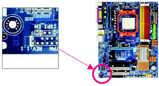
text_image
N31dS2 RFM REV.1.1Table of Contents
Box Contents 6
Optional Items 6
GA-MA790FX-DS5 Motherboard Layout 7
Block Diagram 8
Chapter 1 Hardware Installation 9
1-1 Installation Precautions 9
1-2 Product Specifications 10
1-3 Installing the CPU and CPU Cooler 13
1-3-1 Installing the CPU 13
1-3-2 Installing the CPU Cooler 15
1-4 Installing the Memory 16
1-4-1 Dual Channel Memory Configuration 16
1-4-2 Installing a Memory 17
1-5 Installing an Expansion Card 18
1-6 Back Panel Connectors 20
1-7 Internal Connectors 22
Chapter 2 BIOS Setup 35
2-1 Startup Screen 36
2-2 The Main Menu 37
2-3 Standard CMOS Features 39
2-4 Advanced BIOS Features 42
2-5 Integrated Peripherals 44
2-6 Power Management Setup 49
2-7 PnP/PCI Configurations 51
2-8 PC Health Status 52
2-9 MB Intelligent Tweaker(M.I.T.) 54
2-10 Load Fail-Safe Defaults 58
2-11 Load Optimized Defaults 58
2-12 Set Supervisor/User Password 59
2-13 Save & Exit Setup 60
2-14 Exit Without Saving 60
Chapter 3 Drivers Installation 61
3-1 Installing Chipset Drivers 61
3-2 Software Applications 62
3-3 Driver CD Information 62
3-4 Hardware Information 63
3-5 Contact Us 63
Chapter 4 Unique Features....65
4-1 Xpress Recovery2 65
4-2 BIOS Update Utilities 70
4-2-1 Updating the BIOS with the Q-Flash Utility 70
4-2-2 Updating the BIOS with the @BIOS Utility 73
4-3 EasyTune 5 Pro 75
4-4 Windows Vista ReadyBoost 76
Chapter 5 Appendix ...... 77
5-1 Configuring SATA Hard Drive(s) 77
5-1-1 Configuring AMD SB600 SATA Controllers 77
5-1-2 Configuring GIGABYTE SATA2 SATA Controller 83
5-1-3 Making a SATA RAID/AHCI Driver Diskette 90
5-1-4 Installing the SATA RAID/AHCI Driver and Operating System 91
5-2 Configuring Audio Input and Output 99
5-2-1 Configuring 2/4/5.1/7.1-Channel Audio 99
5-2-2 Installing the S/PDIF In Cable (Optional) 101
5-2-3 Enabling the DTS (Digital Theater Systems) Function 103
5-2-4 Configuring Microphone Recording 104
5-2-5 Using the Sound Recorder 106
5-3 Troubleshooting 107
5-3-1 Frequently Asked Questions 107
5-3-2 Troubleshooting Procedure 108
Regulatory Statements 110
Box Contents
√ GA-MA790FX-DS5 motherboard
☑ Motherboard driver disk
User's Manual
√ Quick Installation Guide
☑ One IDE cable and one floppy disk drive cable
☑ Four SATA 3Gb/s cables
I/O Shield
natural_image
Top-down view of a computer motherboard showing CPU socket, RAM slots, and various electronic components (no readable text or labels)- The box contents above are for reference only and the actual items shall depend on product package you obtain. The box contents are subject to change without notice.
• The motherboard image is for reference only.
Optional Items
☐ 2-port USB 2.0 bracket (Part No. 12CR1-1UB030-51R)
☐ 2-port IEEE 1394a bracket (Part No. 12CF1-1IE008-01R)
☐ 2-port SATA power cable (Part No. 12CF1-2SERPW-01R)
☐ S/PDIF in cable (Part No. 12CR1-1SPDIN-01R)
☐ LPT port cable (Part No. 12CF1-1LP001-01R)
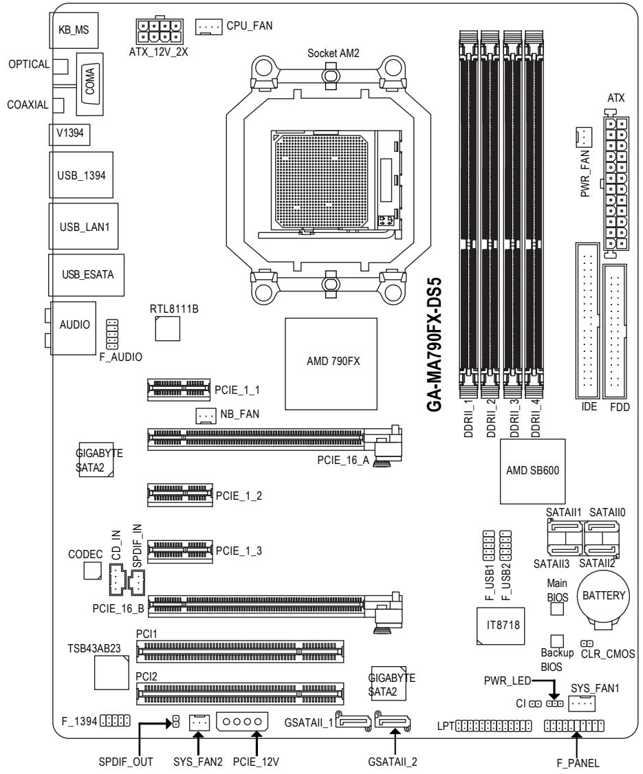
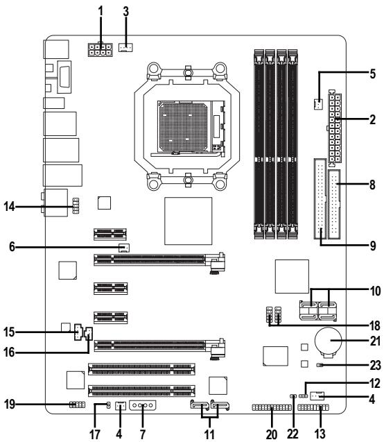
GA-MA790FX-DS5 Motherboard Layout
text_image
KB_MS OPTICAL COMA V1394 USB_1394 USB_LAN1 USB_ESATA AUDIO F_AUDIO ATX_12V_2X CPU_FAN Socket AM2 RTL8111B AMD 790FX PCIE_1_1 NB_FAN PCIE_16_A PCIE_1_2 GIGABYTE $ATA2 CODEC CD_IN SPDIF_IN PCIE_1_3 PCIE_16_B TSB43AB23 PCI1 PCI2 GIGABYTE $ATA2 F_1394 SPDIF_OUT SYS_FAN2 PCIE_12V GSATAII_1 GSATAII_2 GA-MA790FX-DS5 DDRII_1 DDRII_2 DDRII_3 DDRII_4 AMD SB600 SATAII1 SATAII0 SATAII3 SATAII2 Main BIOS IT8718 Backup BIOS CLR_CMOS PWR_LED SYS_FAN1 CI F PANELBlock Diagram
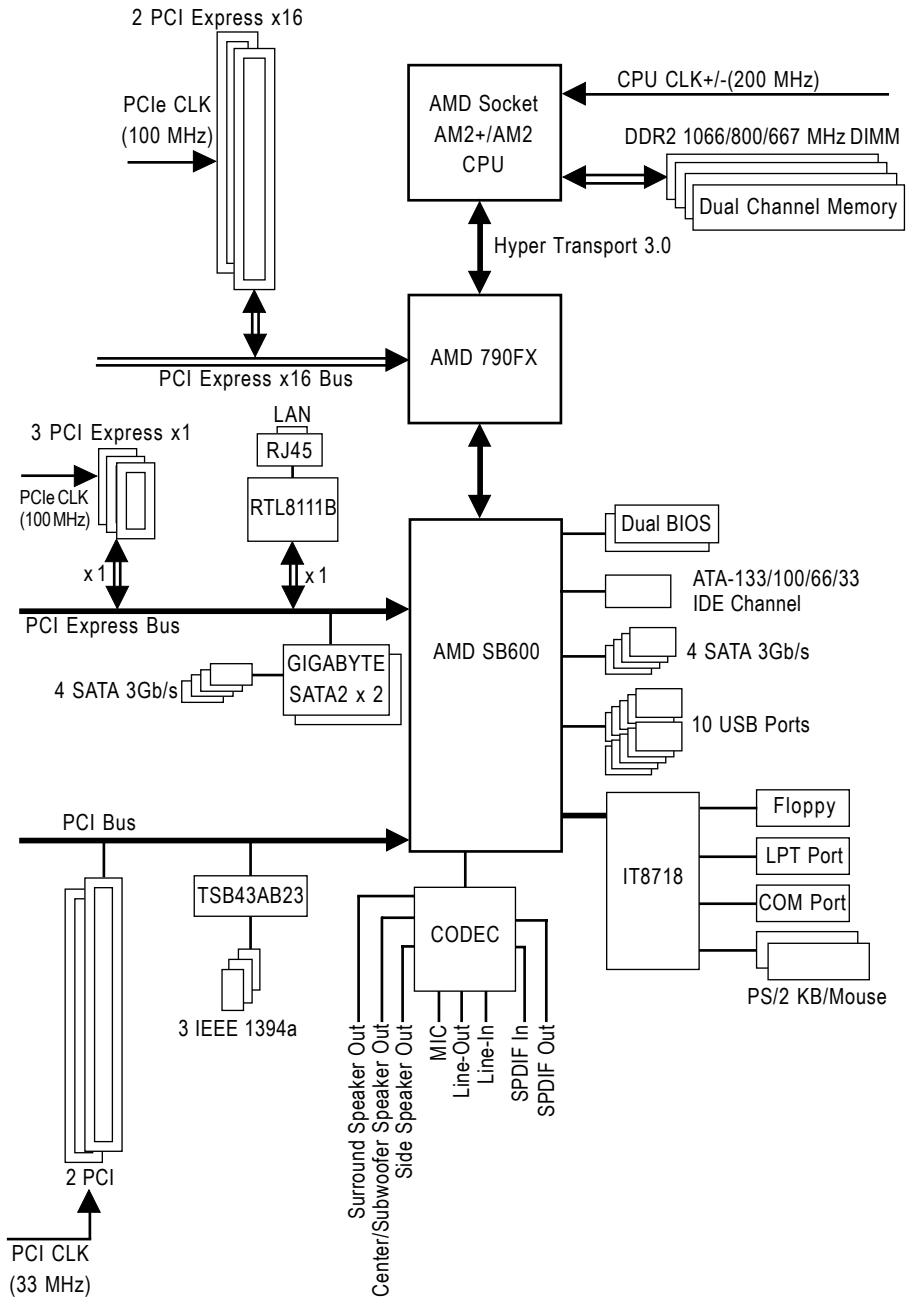
flowchart
graph TD
    A["PCIe CLK (100 MHz)"] --> B["PCI Express x16"]
    B --> C["PCI Express x16 Bus"]
    C --> D["PCI SB600"]
    D --> E["AMD 790FX"]
    E --> F["CPU CLK+/-(200 MHz)"]
    E --> G["DDR2 1066/800/667 MHz DIMM"]
    E --> H["Dual Channel Memory"]
    D --> I["GIGABYTE SATA2 x 2"]
    I --> J["PCI Express Bus"]
    J --> K["PCIe CLK (100 MHz)"]
    K --> L["PCIe Express x1"]
    L --> M["RJ45"]
    M --> N["RTL8111B"]
    N --> O["x 1"]
    O --> P["GIGABYTE SATA2 x 2"]
    P --> Q["PCI Express Bus"]
    Q --> R["PCIe CLK (33 MHz)"]
    R --> S["TSB43AB23"]
    S --> T["3 IEEE 1394a"]
    T --> U["PCI Bus"]
    U --> V["ITO8718"]
    V --> W["Floppy"]
    V --> X["LPT Port"]
    V --> Y["COM Port"]
    V --> Z["PS/2 KB/Mouse"]
    D --> AA["AMD SB600"]
    AA --> AB["Dual BIOS"]
    AB --> AC["ATA-133/100/66/33 IDE Channel"]
    AA --> AD["4 SATA 3Gb/s"]
    AA --> AE["10 USB Ports"]
    AA --> AF["CODEC"]
    AF --> AG["Surrend Speaker Out"]
    AF --> AH["Center/Subwoofer Speaker Out"]
    AF --> AI["Side Speaker Out"]
    AF --> AJ["MIC"]
    AF --> AK["Line-Out"]
    AF --> AL["Line-In"]
    AF --> AM["SPDIF In"]
    AF --> AN["SPDIF Out"]
Chapter 1 Hardware Installation
1-1 Installation Precautions
The motherboard contains numerous delicate electronic circuits and components which can become damaged as a result of electrostatic discharge (ESD). Prior to installation, carefully read the user's manual and follow these procedures:
- Prior to installation, do not remove or break motherboard S/N (Serial Number) sticker or warranty sticker provided by your dealer. These stickers are required for warranty validation.
- Always remove the AC power by unplugging the power cord from the power outlet before installing or removing the motherboard or other hardware components.
- When connecting hardware components to the internal connectors on the motherboard, make sure they are connected tightly and securely.
- When handling the motherboard, avoid touching any metal leads or connectors.
- It is best to wear an electrostatic discharge (ESD) wrist strap when handling electronic components such as a motherboard, CPU or memory. If you do not have an ESD wrist strap, keep your hands dry and first touch a metal object to eliminate static electricity.
- Prior to installing the motherboard, please have it on top of an antistatic pad or within an electrostatic shielding container.
- Before unplugging the power supply cable from the motherboard, make sure the power supply has been turned off.
- Before turning on the power, make sure the power supply voltage has been set according to the local voltage standard.
- Before using the product, please verify that all cables and power connectors of your hardware components are connected.
- To prevent damage to the motherboard, do not allow screws to come in contact with the motherboard circuit or its components.
- Make sure there are no leftover screws or metal components placed on the motherboard or within the computer casing.
- Do not place the computer system on an uneven surface.
- Do not place the computer system in a high-temperature environment.
- Turning on the computer power during the installation process can lead to damage to system components as well as physical harm to the user.
- If you are uncertain about any installation steps or have a problem related to the use of the product, please consult a certified computer technician.
1-2 Product Specifications
| CPU | Support for Socket AM2+/AM2 processors:AMD PhenomTM FX processor/AMD PhenomTM processor/AMD AthlonTM 64 FX processor/AMD AthlonTM 64 X2 Dual-Core processor/AMD AthlonTM 64 processor/AMD SempronTM processor(Go to GIGABYTE's website for the latest CPU support list.) |
| Hyper Transport Bus | 5200/2000 MT/s |
| Chipset | North Bridge: AMD 790FXSouth Bridge: AMD SB600 |
| Memory | 4 x 1.8V DDR2 DIMM sockets supporting up to 16 GB of system memory (Note 1)Dual channel memory architectureSupport for DDR2 1066 (Note 2)/800/667 MHz memory modules(Go to GIGABYTE's website for the latest memory support list.)Support for ECC memory (Note 3) |
| Audio | Realtek ALC889A codecHigh Definition Audio2/4/5.1/7.1-channelSupport for DTS (dts NEO:PC)Support for S/PDIF In/OutSupport for CD In |
| LAN | Realtek 8111B chip (10/100/1000 Mbit) |
| Expansion Slots | 2 x PCI Express x16 slots supporting ATI CrossFireXTM technology(The PCI Express x16 slots conform to PCI Express 2.0 standard.)3 x PCI Express x1 slots2 x PCI slots |
| Storage Interface | South Bridge:- 1 x IDE connector supporting ATA-133/100/66/33 and up to 2 IDE devices- 4 x SATA 3Gb/s connectors (SATAII0, SATAII1, SATAII2, SATAII3)supporting up to 4 SATA 3Gb/s devices- Support for SATA RAID 0, RAID 1 and RAID 0+12 x GIGABYTE SATA2 chip:- 2 x SATA 3Gb/s connectors (GSATAII_1, GSATAII_2) supporting up to2 SATA 3Gb/s devices- 2 x eSATA 3Gb/s ports on the back panel supporting up to 2 SATA3Gb/s devices- Support for SATA RAID 0, RAID 1, and JBODiTE IT8718 chip:- 1 x floppy disk drive connector supporting up to 1 floppy disk drive |
| IEEE 1394 | T.I. TSB43AB23 chipUp to 3 IEEE 1394a ports (2 on the back panel, 1 via the IEEE 1394a bracketconnected to the internal IEEE 1394a header) |
| USB | Integrated in the South BridgeUp to 10 USB 2.0/1.1 ports (6 on the back panel, 4 via the USB brackets connected to the internal USB headers) |
| Internal Connectors | 1 x 24-pin ATX main power connector1 x 8-pin ATX 12V power connector1 x 4-pin PCIe 12V power connector1 x floppy disk drive connector1 x IDE connector6 x SATA 3Gb/s connectors1 x CPU fan header2 x system fan headers1 x power fan header1 x North Bridge fan header1 x front panel header1 x front panel audio header1 x CD In connector1 x S/PDIF In header1 x S/PDIF Out header2 x USB 2.0/1.1 headers1 x IEEE 1394a header1 x parallel port header1 x power LED header1 x chassis intrusion header |
| Back PanelConnectors | 1 x PS/2 keyboard port1 x PS/2 mouse port1 x serial port1 x coaxial S/PDIF Out connector1 x optical S/PDIF Out connector6 x USB 2.0/1.1 ports2 x IEEE 1394a ports1 x RJ-45 port2 x eSATA 3Gb/s ports6 x audio jacks (Center/Subwoofer Speaker Out/Rear Speaker Out/Side Speaker Out/Line In/Line Out/Microphone) |
| I/O Controller | iTE IT8718 chip |
| Hardware Monitor | System voltage detectionCPU/System temperature detectionCPU/System/Power fan speed detectionCPU overheating warningCPU/System/Power fan fail warningCPU/System fan speed control (Note 4) |
| BIOS | ◆ 2 x 4 Mbit flash◆ Use of licensed AWARD BIOS◆ Support for Dual BIOSTM◆ PnP 1.0a, DMI 2.0, SM BIOS 2.4, ACPI 1.0b |
| Unique Features | ◆ Support for @BIOS◆ Support for Download Center◆ Support for Q-Flash◆ Support for EasyTune (Note 5)◆ Support for Xpress Install◆ Support for Xpress Recovery2◆ Support for Virtual Dual BIOS |
| Bundled Software | ◆ Norton Internet Security (OEM version) |
| Overclocking | ◆ Voltage adjustments in BIOS Setup (CPU/DDR2/Chipset/PCIE/FSB/HTT/HTR)allow you to:- Increase CPU voltage (Note 6)- Increase DDR2 voltage by 0.05V to 0.50V with 0.05V increment- Increase Chipset voltage by 0.05V to 0.40V with 0.05V increment- Increase PCI Express voltage by 0.05V to 0.45V with 0.05V increment- Increase FSB voltage by 0.05V to 0.35V with 0.05V increment- Increase HTT voltage by 0.05V to 0.40V with 0.05V increment- Increase HTR voltage by 0.05V to 0.45V with 0.05V increment◆ Frequency adjustments in BIOS Setup (CPU/HT Link/PCIE/DDR2)allow you to:- Adjust CPU host frequency from 200 MHz to 500 MHz with 1 MHz increment- Adjust HT Link frequency- Adjust PCI Express frequency from 100 MHz to 200 MHz with 1 MHz increment- Adjust DDR2 frequency |
| Operating System | ◆ Support for Microsoft® Windows® Vista/XP/2000 |
| Form Factor | ◆ ATX Form Factor; 30.5cm x 24.4cm |
(Note 1) Due to Windows XP 32-bit operating system limitation, when more than 4 GB of physical memory is installed, the actual memory size displayed will be less than 4 GB.
(Note 2) Whether 1066 MHz memory speed is supported depends on the CPU being used.
(Note 3) Use of a CPU that supports ECC is required if you wish to install ECC memory.
(Note 4) Whether the CPU/system fan speed control function is supported will depend on the CPU/system cooler you install.
(Note 5) Available functions in Easytune may differ by motherboard model.
(Note 6) The adjustable CPU voltage range depends on the CPU being used.
1-3 Installing the CPU and CPU Cooler

Read the following guidelines before you begin to install the CPU:
- Make sure that the motherboard supports the CPU.
(Go to GIGABYTE's website for the latest CPU support list.) - Always turn off the computer and unplug the power cord from the power outlet before installing the CPU to prevent hardware damage.
- Locate the pin one of the CPU. The CPU cannot be inserted if oriented incorrectly.
- Apply an even and thin layer of thermal grease on the surface of the CPU.
- Do not turn on the computer if the CPU cooler is not installed, otherwise overheating and damage of the CPU may occur.
- Set the CPU host frequency in accordance with the CPU specifications. It is not recommended that the system bus frequency be set beyond hardware specifications since it does not meet the standard requirements for the peripherals. If you wish to set the frequency beyond the standard specifications, please do so according to your hardware specifications including the CPU, graphics card, memory, hard drive, etc.
1-3-1 Installing the CPU
A. Locate the pin one (denoted by a small triangle) of the CPU socket and the CPU.
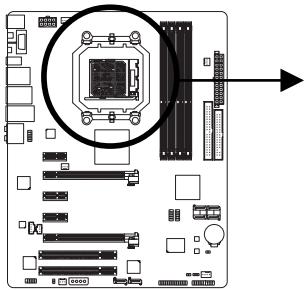
natural_image
Diagram of a computer motherboard showing CPU socket and drive slots (no text or labels)A Small Triangle Mark
Denotes Pin One of the
Socket
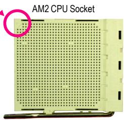
text_image
AM2 CPU SocketA Small Triangle Marking
Denotes CPU Pin One

text_image
AM2 CPU AMD ZI © 2005 AMDB. Follow the steps below to correctly install the CPU into the motherboard CPU socket.

Before installing the CPU, make sure to turn off the computer and unplug the power cord from the power outlet to prevent damage to the CPU.
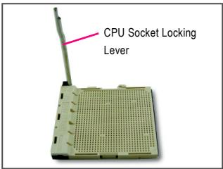
text_image
CPU Socket Locking LeverStep 1:
Completely lift up the CPU socket locking lever.
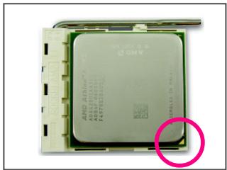
natural_image
Close-up of an AMD CPU processor with a highlighted section (no visible text or symbols on the chip itself)Step 2:
Align the CPU pin one (small triangle marking) with the triangle mark on the CPU socket and gently insert the CPU into the socket. Make sure that the CPU pins fit perfectly into their holes. Once the CPU is positioned into its socket, place one finger down on the middle of the CPU, lowering the locking lever and latching it into the fully locked position.

Do not force the CPU into the CPU socket. The CPU cannot fit in if oriented incorrectly. Adjust the CPU orientation if this occurs.
1-3-2 Installing the CPU Cooler
Follow the steps below to correctly install the CPU cooler on the CPU. (The following procedure uses the GIGABYTE cooler as the example.)
natural_image
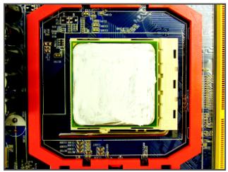
Close-up of a microchip mounted on a circuit board (no visible text or symbols)Step 1:
Apply an even and thin layer of thermal grease on the surface of the installed CPU.
natural_image
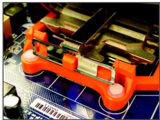
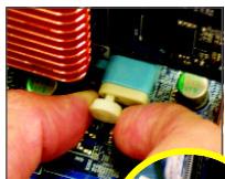
Close-up of an orange robotic gripper on a blue circuit board (no visible text or symbols)Step 3:
Hook the CPU cooler clip to the mounting lug on one side of the retention frame. On the other side, push straight down on the CPU cooler clip to hook it to the mounting lug on the retention frame.
natural_image
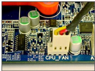
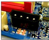
Close-up of a blue printed circuit board with electronic components and a CPU fan (no readable text or symbols)Step 5:
Finally, attach the power connector of the CPU cooler to the CPU fan header (CPU_FAN) on the motherboard.
natural_image
Close-up of a computer monitor with an orange display unit and keyboard, showing no visible text or symbols.Step 2:
Place the CPU cooler on the CPU.
natural_image
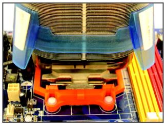
Close-up of an electronic circuit board with a mechanical component and wiring, no visible text or symbolsStep 4:
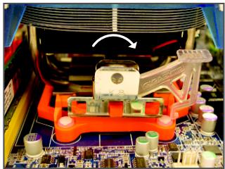
Turn the cam handle from the left side to the right side (as the picture above shows) to lock into place. (Refer to your CPU cooler installation manual for instructions on installing the cooler.)

Use extreme care when removing the CPU cooler because the thermal grease/tape between the CPU cooler and CPU may adhere to the CPU. Inadequately removing the CPU cooler may damage the CPU.
1-4 Installing the Memory

Read the following guidelines before you begin to install the memory:
- Make sure that the motherboard supports the memory. It is recommended that memory of the same capacity, brand, speed, and chips be used.
(Go to GIGABYTE's website for the latest memory support list.) - Always turn off the computer and unplug the power cord from the power outlet before installing the memory to prevent hardware damage.
- Memory modules have a foolproof design. A memory module can be installed in only one direction. If you are unable to insert the memory, switch the direction.
1-4-1 Dual Channel Memory Configuration
This motherboard provides four DDR2 memory sockets and supports Dual Channel Technology. After the memory is installed, the BIOS will automatically detect the specifications and capacity of the memory. Enabling Dual Channel memory mode will double the original memory bandwidth.
The four DDR2 memory sockets are divided into two channels and each channel has two memory sockets as following:
▶ Channel 0: DDRII_1, DDRII_3
▶ Channel 1: DDRII_2, DDRII_4

text_image
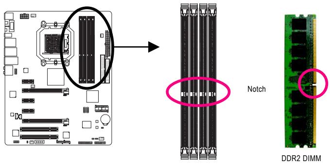
Diagram of a computer motherboard with an inset showing a CD412 memory card layout and its corresponding DDR1_1 to DDR1_4 interface.▶ Dual Channel Memory Configurations Table
(SS=Single-Sided, DS=Double-Sided, "- -" = No Memory)

If two memory modules are to be installed, it is recommended that you install them in the DDRII_1 and DDRII_2 sockets.
Due to CPU limitation, read the following guidelines before installing the memory in Dual Channel mode.
- Dual Channel mode cannot be enabled if only one DDR2 memory module is installed.
- When enabling Dual Channel mode with two or four memory modules, it is recommended that memory of the same capacity, brand, speed, and chips be used and installed in the same colored DDR2 sockets for optimum performance.
1-4-2 Installing a Memory

Before installing a memory module, make sure to turn off the computer and unplug the power cord from the power outlet to prevent damage to the memory module. DDR2 DIMMs are not compatible to DDR DIMMs. Be sure to install DDR2 DIMMs on this motherboard.
text_image
Notch DDR2 DIMMA DDR2 memory module has a notch, so it can only fit in one direction. Follow the steps below to correctly install your memory modules in the memory sockets.
natural_image
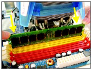
Close-up of a computer motherboard with a green and red RAM module being processed, no visible text or symbols.Step 1:
Note the orientation of the memory module. Spread the retaining clips at both ends of the memory socket. Place the memory module on the socket. As indicated in the picture on the left, place your fingers on the top edge of the memory, push down on the memory and insert it vertically into the memory socket.
natural_image
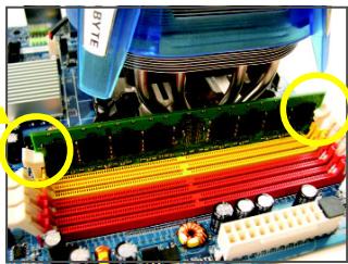
Close-up of a computer motherboard with visible RAM slots and connectors (no text or symbols)Step 2:
The clips at both ends of the socket will snap into place when the memory module is securely inserted.
1-5 Installing an Expansion Card

Read the following guidelines before you begin to install an expansion card:
- Make sure the motherboard supports the expansion card. Carefully read the manual that came with your expansion card.
- Always turn off the computer and unplug the power cord from the power outlet before installing an expansion card to prevent hardware damage.
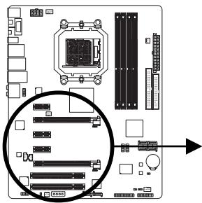
natural_image
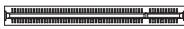
Diagram of a computer motherboard with slots and connectors, highlighting a specific slot (no text or labels present)PCI Express x1 Slot

PCI Express x16 Slot
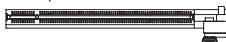
PCI Slot
Follow the steps below to correctly install your expansion card in the expansion slot.
- Locate an expansion slot that supports your card. Remove the metal slot cover from the chassis back panel.
- Align the card with the slot, and press down on the card until it is fully seated in the slot.
- Make sure the metal contacts on the card are completely inserted into the slot.
- Secure the card's metal bracket to the chassis back panel with a screw.
- After installing all expansion cards, replace the chassis cover(s).
- Turn on your computer. If necessary, go to BIOS Setup to make any required BIOS changes for your expansion card(s).
- Install the driver provided with the expansion card in your operating system.
Example: Installing and Removing a PCI Express x16 Graphics Card:
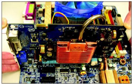
natural_image
Close-up of hands operating a computer motherboard with visible CPU socket and heatsink (no text or symbols)• Installing a Graphics Card:
Gently insert the graphics card into the PCI Express x16 slot. Make sure the small white-drawable bar securely locks the graphics card.
natural_image
Close-up of hands adjusting a component on a computer motherboard with visible circuit board and copper heating element (no text or symbols)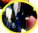
- Removing the Card:
Pull out the small white-drawable bar at the end of the PCI Express x16 slot to release the card and then pull the card straight up from the slot.
You can also press the latch on the back of the white-drawable bar to release the card.
natural_image
Close-up of a blue circuit board with electronic components and connectors (no visible text or symbols)- The motherboard provides a PCIE_12V power connector, which can supply extra power to the onboard PCI Express x16 slots. When you install two graphics cards, connect the power cable from your power supply to this connector.
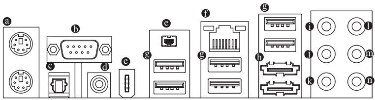
1-6 Back Panel Connectors
text_image
a b c d e f g h i j k l m nPS/2 Keyboard and PS/2 Mouse Port
Use the upper port (green) to connect a PS/2 mouse and the lower port (purple) to connect a PS/2 keyboard.
b Serial Port
Use the serial port to connect devices such as a mouse, modem or other peripherals.
© Optical S/PDIF Out Connector
This connector provides digital audio out to an external audio system that supports digital optical audio. Before using this feature, ensure that your audio system provides an optical digital audio in connector.
Coaxial S/PDIF Out Connector
This connector provides digital audio out to an external audio system that supports digital coaxial audio. Before using this feature, ensure that your audio system provides a coaxial digital audio in connector.
e IEEE 1394a Port
The IEEE 1394 port supports the IEEE 1394a specification, featuring high speed, high bandwidth and hotplug capabilities. Use this port for an IEEE 1394a device.
f RJ-45 LAN Port
The Gigabit Ethernet LAN port provides Internet connection at up to 1 Gbps data rate. The following describes the states of the LAN port LEDs.
Connection/
Speed LED Activity LED
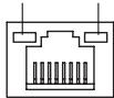
LAN Port
Connection/Speed LED:
| State | Description |
| Orange | 1 Gpbs data rate |
| Green | 100 Mpbs data rate |
| Off | 10 Mpbs data rate |
Activity LED:
| State | Description |
| Blinking | Data transmission or receiving is occurring |
| Off | No data transmission or receiving is occurring |
USB Port
The USB port supports the USB 2.0/1.1 specification. Use this port for USB devices such as an USB keyboard/mouse, USB printer, USB flash drive and etc.

- When removing the cable connected to a back panel connector, first remove the cable from your device and then remove it from the motherboard.
- When removing the cable, pull it straight out from the connector. Do not rock it side to side to prevent an electrical short inside the cable connector.
eSATA 3Gb/s Port
The eSATA 3Gb/s port supported by the GIGABYTE SATA2 chip conforms to SATA 3Gb/s standard and is compatible with SATA 1.5Gb/s standard. Use the port to connect an external SATA device or a SATA port multiplier.
i Center/Subwoofer Speaker Out Jack (Orange)
Use this audio jack to connect center/subwoofer speakers in a 5.1/7.1-channel audio configuration.
- Rear Speaker Out Jack (Black)
Use this audio jack to connect rear speakers in a 4/5.1/7.1-channel audio configuration.
Side Speaker Out Jack (Gray)
Use this audio jack to connect side speakers in a 7.1-channel audio configuration.
① Line In Jack (Blue)
The default line in jack. Use this audio jack for line in devices such as an optical drive, walkman, etc.
m Line Out Jack (Green)
The default line out jack. Use this audio jack for a headphone or 2-channel speaker. This jack can be used to connect front speakers in a 4/5.1/7.1-channel audio configuration.
⑪ Mic In Jack (Pink)
The default Mic in jack. Microphones must be connected to this jack.

In addition to the default speakers settings, the ① \~ ⑪ audio jacks can be reconfigured to perform different functions via the audio software. Only microphones still MUST be connected to the default Mic in jack (⑩). Refer to the instructions on setting up a 2/4/5.1/7.1-channel audio configuration in Chapter 5, "Configuring 2/4/5.1/7.1-Channel Audio."
1-7 Internal Connectors
text_image
Labeled diagram of a computer motherboard showing internal components and connectors with numbered partsRead the following guidelines before connecting external devices:
- First make sure your devices are compliant with the connectors you wish to connect.
- Before installing the devices, be sure to turn off the devices and your computer. Unplug the power cord from the power outlet to prevent damage to the devices.
- After installing the device and before turning on the computer, make sure the device cable has been securely attached to the connector on the motherboard.
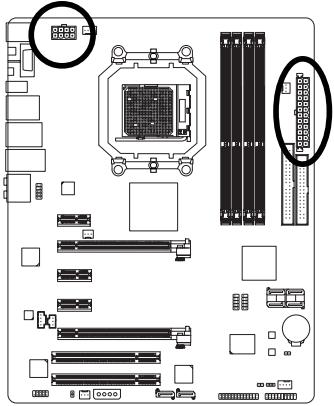
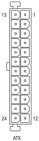
1/2) ATX\_12V\_2X/ATX (2x4 12V Power Connector and 2x12 Main Power Connector)
With the use of the power connector, the power supply can supply enough stable power to all the components on the motherboard. Before connecting the power connector, first make sure the power supply is turned off and all devices are properly installed. The power connector possesses a foolproof design. Connect the power supply cable to the power connector in the correct orientation. The 12V power connector mainly supplies power to the CPU. If the 12V power connector is not connected, the computer will not start.

- To meet expansion requirements, it is recommended that a power supply that can withstand high power consumption be used (400W or greater). If a power supply is used that does not provide the required power, the result can lead to an unstable or unbootable system.
- The power connectors are compatible with power supplies with 2x2 12V and 2x10 power connectors. When using a power supply providing a 2x4 12V and a 2x12 power connector, remove the protective covers from the 12V power connector and the main power connector on the motherboard. Do not insert the power supply cables into pins under the protective covers when using a power supply providing a 2x2 12V and a 2x10 power connector.
natural_image
Top-down view of a computer motherboard showing CPU socket, RAM slots, and memory card (no text or labels)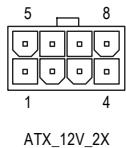
text_image
5 8 1 4 ATX_12V_2XATX_12V_2X:
| Pin No. | Definition |
| 1 | GND (Only for 2x4 pin 12V) |
| 2 | GND (Only for 2x4 pin 12V) |
| 3 | GND |
| 4 | GND |
| 5 | +12V (Only for 2x4 pin 12V) |
| 6 | +12V (Only for 2x4 pin 12V) |
| 7 | +12V |
| 8 | +12V |
text_image
13 1 24 12 ATXATX :
| Pin No. | Definition | Pin No. | Definition |
| 1 | 3.3V | 13 | 3.3V |
| 2 | 3.3V | 14 | -12V |
| 3 | GND | 15 | GND |
| 4 | +5V | 16 | PS_ON(soft On/Off) |
| 5 | GND | 17 | GND |
| 6 | +5V | 18 | GND |
| 7 | GND | 19 | GND |
| 8 | Power Good | 20 | -5V |
| 9 | 5V SB(stand by +5V) | 21 | +5V |
| 10 | +12V | 22 | +5V |
| 11 | +12V (Only for 2x12 pin ATX) | 23 | +5V (Only for 2x12 pin ATX) |
| 12 | 3.3V (Only for 2x12 pin ATX) | 24 | GND (Only for 2x12 pin ATX) |
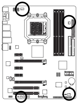
3/4/5) CPU\_FAN/SYS\_FAN1/SYS\_FAN2/PWR\_FAN (Fan Headers)
The motherboard has a 4-pin CPU fan header (CPU_FAN), a 4-pin (SYS_FAN1) and a 3-pin (SYS_FAN2) system fan header, and a 3-pin power fan header (PWR_FAN). Each fan header supplies a +12V power voltage and possesses a foolproof insertion design. When connecting a fan cable, be sure to connect it in the correct orientation. Most fans are designed with color-coded power connector wires. A red power connector wire indicates a positive connection and requires a +12V voltage. The black connector wire is the ground wire. The motherboard supports CPU fan speed control, which requires the use of a CPU fan with fan speed control design. For optimum heat dissipation, it is recommended that a system fan be installed inside the chassis.
natural_image
Top-down view of a computer motherboard showing CPU socket, RAM slots, and memory drive (no text or labels visible)
CPU_FAN

SYS_FAN1

SYS_FAN2

PWR_FAN
CPU_FAN:
| Pin No. | Definition |
| 1 | GND |
| 2 | +12V / Speed Control |
| 3 | Sense |
| 4 | Speed Control |
SYS_FAN1:
| Pin No. | Definition |
| 1 | GND |
| 2 | +12V / Speed Control |
| 3 | Sense |
| 4 | +5V |
SYS_FAN2/PWR_FAN:
| Pin No. | Definition |
| 1 | GND |
| 2 | +12V |
| 3 | Sense |
6) NB\_FAN (North Bridge Fan Header)
Connect the North Bridge fan cable to this header. The fan header has a foolproof insertion design. When connecting a fan cable, be sure to connect it in the correct orientation. Most fans are designed with color-coded power connector wires. A red power connector wire indicates a positive connection and requires a +12V voltage. The black connector wire is the ground wire.
natural_image
Exploded view diagram of a computer motherboard showing CPU socket, RAM slots, and various connectors (no text or labels)
| Pin No. | Definition |
| 1 | GND |
| 2 | +12V |
| 3 | NC |

- Be sure to connect fan cables to the fan headers to prevent your CPU, North Bridge and system from overheating. Overheating may result in damage to the CPU/North Bridge or the system may hang.
- These fan headers are not configuration jumper blocks. Do not place a jumper cap on the headers.
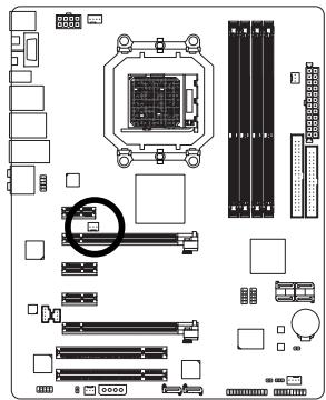
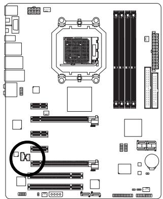
7) PCIE\_12V (Power Connector)
This power connector can supply extra power to the PCI Express x16 slots on the motherboard. Connect the power supply cable to this connector when using two graphics cards. Failure to do so may lead to an unstable system.
natural_image
Top-down schematic of a computer motherboard showing CPU socket, RAM slots, and memory drive (no text or labels)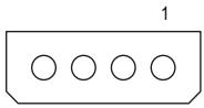
natural_image
Simple diagram of four circles inside a rectangular box, labeled '1' at top (no text or symbols on the shapes)| Plin No. | Definition |
| 1 | NC |
| 2 | GND |
| 3 | GND |
| 4 | +12V |
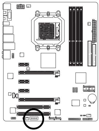
8) FDD (Floppy Disk Drive Connector)
This connector is used to connect a floppy disk drive. The types of floppy disk drives supported are: 360 KB, 720 KB, 1.2 MB, 1.44 MB, and 2.88 MB. Before connecting a floppy disk drive, be sure to locate pin 1 of the connector and the floppy disk drive cable. The pin 1 of the cable is typically designated by a stripe of different color.
natural_image
Top-down schematic of a computer motherboard showing CPU socket, RAM slots, and memory card layout (no text or labels)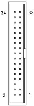
text_image
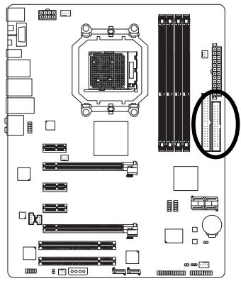
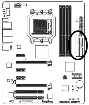
34 33 2 19) IDE (IDE Connector)
The IDE connector supports up to two IDE devices such as hard drives and optical drives. Before attaching the IDE cable, locate the foolproof groove on the connector. If you wish to connect two IDE devices, remember to set the jumpers and the cabling according to the role of the IDE devices (for example, master or slave). (For information about configuring master/slave settings for the IDE devices, read the instructions from the device manufacturers.)
natural_image
Diagram of a computer motherboard showing CPU socket, RAM slots, and memory card layout (no text or labels)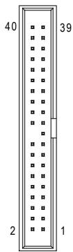
text_image
40 39 2 110) SATAII0/1/2/3 (SATA 3Gb/s Connectors, Controlled by SB600, Orange)
The SATA connectors conform to SATA 3Gb/s standard and are compatible with SATA 1.5Gb/s standard. Each SATA connector supports a single SATA device. The AMD SB600 controller supports RAID 0, RAID 1 and RAID 0+1. Refer to Chapter 5, "Configuring SATA Hard Drive(s)," for instructions on configuring a RAID array.
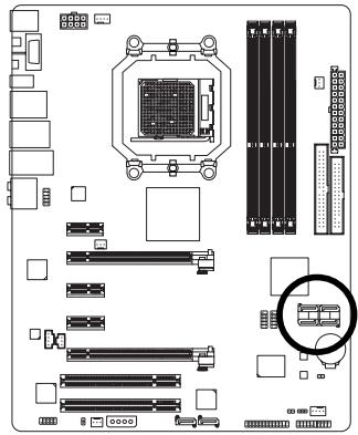
natural_image
Top-down schematic of a computer motherboard showing CPU socket, RAM slots, and memory card layout (no text or labels)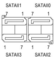
text_image
SATAII1 7 1 7 1 SATAII0 SATAII3 1 7 1 7 SATAII2| Pin No. | Definition |
| 1 | GND |
| 2 | TXP |
| 3 | TXN |
| 4 | GND |
| 5 | RXN |
| 6 | RXP |
| 7 | GND |
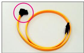
natural_image
Yellow cable with black connectors, one circled in pink (no text or symbols visible)Please connect the L-shaped end of the SATA 3Gb/s cable to your SATA hard drive.

- A RAID 0 or RAID 1 configuration requires at least two hard drives. If more than two hard drives are to be used, the total number of hard drives must be an even number.
- A RAID 0+1 configuration requires at least four hard drives and the total number of hard drives must be an even number.
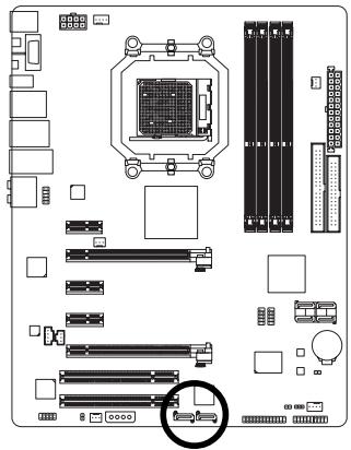
11) GSATAII\_1/GSATAII\_2 (SATA 3Gb/s Connectors, Controlled by GIGABYTE SATA2, Purple)
The SATA connectors conform to SATA 3Gb/s standard and are compatible with SATA 1.5Gb/s standard. Each SATA connector supports a single SATA device. The GIGABYTE SATA2 controller supports RAID 0 and RAID 1. Refer to Chapter 5, "Configuring SATA Hard Drive(s)," for instructions on configuring a RAID array.
natural_image
Top-down schematic of a computer motherboard showing CPU socket, RAM slots, and memory card (no text or labels)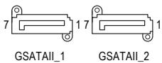
text_image
7 17 GSATAII_1 1 GSATAII_2| Pin No. | Definition |
| 1 | GND |
| 2 | TXP |
| 3 | TXN |
| 4 | GND |
| 5 | RXN |
| 6 | RXP |
| 7 | GND |
natural_image
Yellow cable with black connectors, one circled in pink (no text or symbols visible)Please connect the L-shaped end of the SATA 3Gb/s cable to your SATA hard drive.

A RAID 0 or RAID 1 configuration requires two hard drives.
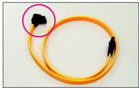
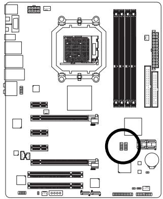
12) PWR\_LED (System Power LED Header)
This header can be used to connect a system power LED on the chassis to indicate system power status. The LED is on when the system is operating. The LED keeps blinking when the system is in S1 sleep state. The LED is off when the system is in S3/S4 sleep state or powered off (S5).
text_image
Diagram of a computer motherboard layout with labeled components and connectors1
| Pin No. | Definition |
| 1 | MPD+ |
| 2 | MPD- |
| 3 | MPD- |
| System Status | LED |
| S0 | On |
| S1 | Blinking |
| S3/S4/S5 | Off |
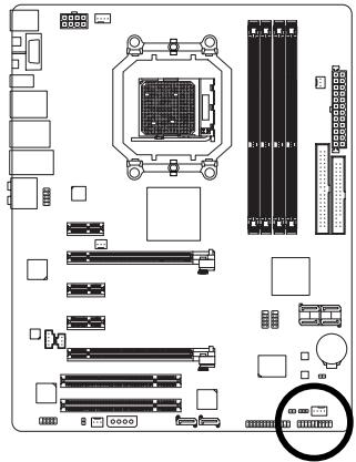
13) F\_PANEL (Front Panel Header)
Connect the power switch, reset switch, speaker and system status indicator on the chassis front panel to this header according to the pin assignments below. Note the positive and negative pins before connecting the cables.
natural_image
Top-down schematic of a computer motherboard showing CPU socket, RAM slots, and memory card (no text or labels)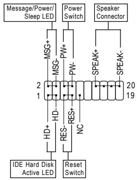
flowchart
graph TD
    A["Message/Power/Sleep LED"] --> B["MSG+"]
    B --> C["MSG-"]
    C --> D["HD+"]
    D --> E["IDE Hard Disk Active LED"]
    F["Power Switch"] --> G["PW+"]
    G --> H["HD-"]
    H --> I["RES-"]
    I --> J["Reset Switch"]
    K["Speaker Connector"] --> L["SPEAK+"]
    L --> M["SPEAK-"]
    N["20 19"] --> O["2"]
    N --> P["19"]
- MSG (Message/Power/Sleep LED, Yellow):
| System Status | LED |
| S0 | On |
| S1 | Blinking |
| S3/S4/S5 | Off |
Connects to the power status indicator on the chassis front panel. The LED is on when the system is operating. The LED keeps blinking when the system is in S1 sleep state. The LED is off when the system is in S3/S4 sleep state or powered off (S5).
• PW (Power Switch, Red):
Connects to the power switch on the chassis front panel. You may configure the way to turn off your system using the power switch (refer to Chapter 2, "BIOS Setup," "Power Management Setup," for more information).
- SPEAK (Speaker, Orange):
Connects to the speaker on the chassis front panel. The system reports system startup status by issuing a beep code. One single short beep will be heard if no problem is detected at system startup. If a problem is detected, the BIOS may issue beeps in different patterns to indicate the problem. Refer to Chapter 5, "Troubleshooting," for information about beep codes.
• HD (IDE Hard Drive Activity LED, Blue)
Connects to the hard drive activity LED on the chassis front panel. The LED is on when the hard drive is reading or writing data.
• RES (Reset Switch, Green):
Connects to the reset switch on the chassis front panel. Press the reset switch to restart the computer if the computer freezes and fails to perform a normal restart.
- NC (Purple):
No connection

The front panel design may differ by chassis. A front panel module mainly consists of power switch, reset switch, power LED, hard drive activity LED, speaker and etc. When connecting your chassis front panel module to this header, make sure the wire assignments and the pin assignments are matched correctly.
14) F\_AUDIO (Front Panel Audio Header)
The front panel audio header supports Intel High Definition audio (HD) and AC'97 audio. You may connect your chassis front panel audio module to this header. Make sure the wire assignments of the module connector match the pin assignments of the motherboard header. Incorrect connection between the module connector and the motherboard header will make the device unable to work or even damage it.
text_image
Diagram of a computer motherboard layout with labeled components and numbered partsFor HD Front Panel Audio:
| Pin No. | Definition |
| 1 | MIC2_L |
| 2 | GND |
| 3 | MIC2_R |
| 4 | -ACZ_DET |
| 5 | LINE2_R |
| 6 | GND |
| 7 | FAUDIO_JD |
| 8 | No Pin |
| 9 | LINE2_L |
| 10 | GND |
For AC'97 Front Panel Audio:
| Pin No. | Definition |
| 1 | MIC |
| 2 | GND |
| 3 | MIC Power |
| 4 | NC |
| 5 | Line Out (R) |
| 6 | NC |
| 7 | NC |
| 8 | No Pin |
| 9 | Line Out (L) |
| 10 | NC |

- The front panel audio header supports HD audio by default. If your chassis provides an AC'97 front panel audio module, refer to the instructions on how to activate AC'97 functionality via the audio software in Chapter 5, "Configuring 2/4/5.1/7.1-Channel Audio."
- When using an AC'97 front panel audio module, you can use either the front or the back panel audio connectors, but not both at the same time.
- Some chassis provide a front panel audio module that has separated connectors on each wire instead of a single plug. For information about connecting the front panel audio module that has different wire assignments, please contact the chassis manufacturer.
15) CD\_IN (CD In Connector, Black)
You may connect the audio cable that came with your optical drive to the header.
natural_image
Top-down schematic of a computer motherboard layout showing CPU socket, RAM slots, and various components (no text or labels)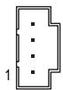
| Pin No. | Definition |
| 1 | CD-L |
| 2 | GND |
| 3 | GND |
| 4 | CD-R |
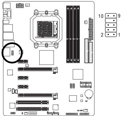
16) SPDIF\_IN (S/PDIF In Header, Red)
This header supports digital S/PDIF in and can connect to an audio device that supports digital audio out via an optional S/PDIF in cable. For purchasing the optional S/PDIF in cable, please contact the local dealer.
natural_image
Exploded view diagram of a computer motherboard showing CPU socket, RAM slots, and memory card (no text or labels)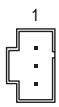
| Pin No. | Definition |
| 1 | Power |
| 2 | SPDIFI |
| 3 | GND |
17) SPDIF\_OUT (S/PDIF Out Header)
This header supports digital S/PDIF out and connects a S/PDIF digital audio cable (provided by expansion cards) for digital audio output from your motherboard to certain expansion cards like graphics cards and sound cards. For example, some graphics cards may require you to use a S/PDIF digital audio cable for digital audio output from your motherboard to your graphics card if you wish to connect an HDMI display to the graphics card and have digital audio output from the HDMI display at the same time. For information about connecting the S/PDIF digital audio cable, carefully read the manual for your expansion card.
natural_image
Exploded view diagram of a computer motherboard showing CPU socket, RAM slots, and memory card (no text or labels)1 8
| Pin No. | Definition |
| 1 | SPDIFO |
| 2 | GND |
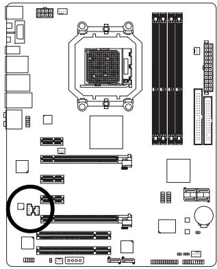
18) F\_USB1/F\_USB2 (USB Headers, Yellow)
The headers conform to USB 2.0/1.1 specification. Each USB header can provide two USB ports via an optional USB bracket. For purchasing the optional USB bracket, please contact the local dealer.
natural_image
Top-down schematic of a computer motherboard layout showing CPU socket, RAM slots, and memory components (no text or labels)
| Pin No. | Definition |
| 1 | Power (5V) |
| 2 | Power (5V) |
| 3 | USB DX- |
| 4 | USB DY- |
| 5 | USB DX+ |
| 6 | USB DY+ |
| 7 | GND |
| 8 | GND |
| 9 | No Pin |
| 10 | NC |

- Do not plug the IEEE 1394 bracket (2x5-pin) cable into the USB header.
- Prior to installing the USB bracket, be sure to turn off your computer and unplug the power cord from the power outlet to prevent damage to the USB bracket.
19) F\_1394 (IEEE 1394a Header, Gray)
The header conforms to IEEE 1394a specification. The IEEE 1394a header can provide one IEEE 1394a ports via an optional IEEE 1394a bracket. For purchasing the optional IEEE 1394a bracket, please contact the local dealer.
natural_image
Top-down schematic of a computer motherboard showing CPU socket, RAM slots, and various connectors (no text or labels)
| Pin No. | Definition |
| 1 | TPA+ |
| 2 | TPA- |
| 3 | GND |
| 4 | GND |
| 5 | TPB+ |
| 6 | TPB- |
| 7 | Power (12V) |
| 8 | Power (12V) |
| 9 | No Pin |
| 10 | GND |

- Do not plug the USB bracket cable into the IEEE 1394a header.
- Prior to installing the IEEE 1394a bracket, be sure to turn off your computer and unplug the power cord from the power outlet to prevent damage to the IEEE 1394a bracket.
- To connect an IEEE 1394a device, attach one end of the device cable to your computer and then attach the other end of the cable to the IEEE 1394a device. Ensure that the cable is securely connected.
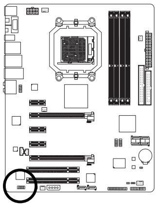
20) LPT (Parallel Port Header)
The LPT header can provide one parallel port via an optional LPT port cable. For purchasing the optional LPT port cable, please contact the local dealer.

natural_image
Top-down schematic of a computer motherboard showing CPU socket, RAM slots, and memory drive components (no text or labels)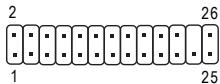
text_image
2 1 26 25| Pin No. | Definition | Pin No. | Definition |
| 1 | STB- | 14 | GND |
| 2 | AFD- | 15 | PD6 |
| 3 | PD0 | 16 | GND |
| 4 | ERR- | 17 | PD7 |
| 5 | PD1 | 18 | GND |
| 6 | INIT- | 19 | ACK- |
| 7 | PD2 | 20 | GND |
| 8 | SLIN- | 21 | BUSY |
| 9 | PD3 | 22 | GND |
| 10 | GND | 23 | PE |
| 11 | PD4 | 24 | No Pin |
| 12 | GND | 25 | SLCT |
| 13 | PD5 | 26 | GND |
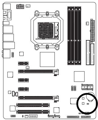
21) BATTERY
The battery provides power to keep the values (such as BIOS configurations, date, and time information) in the CMOS when the computer is turned off. Replace the battery when the battery voltage drops to a low level, or the CMOS values may not be accurate or may be lost.
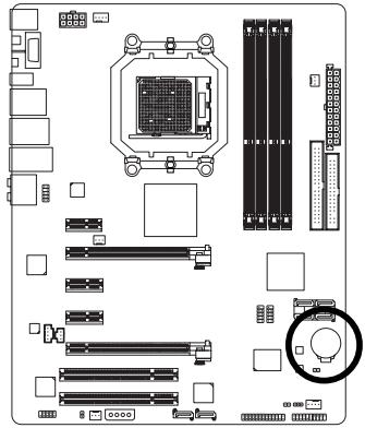
text_image
Diagram of a computer motherboard layout with labeled components and connectors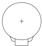
natural_image
Simple line drawing of a circular object with a plus sign at the center and a rectangular base (no text or symbols)You may clear the CMOS values by removing the battery:
- Turn off your computer and unplug the power cord.
- Gently remove the battery from the battery holder and wait for one minute. (Or use a metal object like a screwdriver to touch the positive and negative terminals of the battery holder, making them short for 5 seconds.)
- Replace the battery.
- Plug in the power cord and restart your computer.

• Always turn off your computer and unplug the power cord before replacing the battery.
- Replace the battery with an equivalent one. Danger of explosion if the battery is replaced with an incorrect model.
- Contact the place of purchase or local dealer if you are not able to replace the battery by yourself or uncertain about the battery model.
- When installing the battery, note the orientation of the positive side (+) and the negative side (-) of the battery (the positive side should face up).
• Used batteries must be handled in accordance with local environmental regulations.
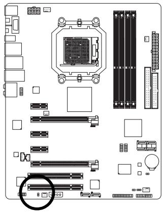
22) CI (Chassis Intrusion Header)
This motherboard provides a chassis detection feature that detects if the chassis cover has been removed. This function requires a chassis with chassis intrusion detection design.
natural_image
Top-down schematic of a computer motherboard showing CPU socket, RAM slots, and memory layout (no text or labels)1
| Pin No. | Definition |
| 1 | Signal |
| 2 | GND |
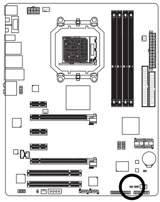
23) CLR\_CMOS (Clearing CMOS Jumper)
Use this jumper to clear the CMOS values (e.g. date information and BIOS configurations) and reset the CMOS values to factory defaults. To clear the CMOS values, place a jumper cap on the two pins to temporarily short the two pins or use a metal object like a screwdriver to touch the two pins for a few seconds.
natural_image
Top-down schematic of a computer motherboard showing CPU socket, RAM slots, and memory drive components (no text or labels)Open: Normal
Short: Clear CMOS Values

- Always turn off your computer and unplug the power cord from the power outlet before clearing the CMOS values.
- After clearing the CMOS values and before turning on your computer, be sure to remove the jumper cap from the jumper. Failure to do so may cause damage to the motherboard.
- After system restart, go to BIOS Setup to load factory defaults (select Load Optimized Defaults) or manually configure the BIOS settings (refer to Chapter 2, "BIOS Setup," for BIOS configurations).
Chapter 2 BIOS Setup
BIOS (Basic Input and Output System) records hardware parameters of the system in the CMOS on the motherboard. Its major functions include conducting the Power-On Self-Test (POST) during system startup, saving system parameters and loading operating system, etc. BIOS includes a BIOS Setup program that allows the user to modify basic system configuration settings or to activate certain system features. When the power is turned off, the battery on the motherboard supplies the necessary power to the CMOS to keep the configuration values in the CMOS.
To access the BIOS Setup program, press the
To upgrade the BIOS, use either the GIGABYTE Q-Flash or @BIOS utility.
- Q-Flash allows the user to quickly and easily upgrade or back up BIOS without entering the operating system.
- @BIOS is a Windows-based utility that searches and downloads the latest version of BIOS from the Internet and updates the BIOS.
For instructions on using the Q-Flash and @BIOS utilities, refer to Chapter 4, "BIOS Update Utilities."

- Because BIOS flashing is potentially risky, if you do not encounter problems using the current version of BIOS, it is recommended that you not flash the BIOS. To flash the BIOS, do it with caution. Inadequate BIOS flashing may result in system malfunction.
- BIOS will emit a beep code during the POST. Refer to Chapter 5, "Troubleshooting," for the beep codes description.
- It is recommended that you not alter the default settings (unless you need to) to prevent system instability or other unexpected results. Inadequately altering the settings may result in system's failure to boot. If this occurs, try to clear the CMOS values and reset the board to default values. (Refer to the "Load Optimized Defaults" section in this chapter or introductions of the battery/clearing CMOS jumper in Chapter 1 for how to clear the CMOS values.)
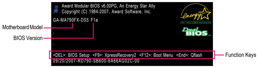
2-1 Startup Screen
The following screen may appear when the computer boots.
text_image
Award Modular BIOS v6.00PG, An Energy Star Ally Copyright (C) 1984-2007, Award Software, Inc. GA-MA790FX-DS5 F1a Motherboard Model BIOS VersionFunction Keys:
: BIOS Setup
Press the
: Xpress Recovery2
If you have ever entered Xpress Recovery2 to back up hard drive data using the motherboard driver disk, the
: Boot Menu
Boot Menu allows you to set the first boot device without entering BIOS Setup. In Boot Menu, use the up arrow key <> or the down arrow key <> to select the first boot device, then press
Note: The setting in Boot Menu is effective for one time only. After system restart, the device boot order will still be based on BIOS Setup settings. You can access Boot Menu again to change the first boot device setting as needed.
: Q-Flash
Press the
2-2 The Main Menu
Once you enter the BIOS Setup program, the Main Menu (as shown below) appears on the screen. Use arrow keys to move among the items and press
(Sample BIOS Version: F1a)
CMOS Setup Utility-Copyright (C) 1984-2007 Award Software
| Standard CMOS FeaturesAdvanced BIOS FeaturesIntegrated PeripheralsPower Management SetupPnP/PCI ConfigurationsPC Health StatusMB Intelligent Tweaker(M.I.T.) | Load Fail-Safe DefaultsLoad Optimized DefaultsSet Supervisor PasswordSet User PasswordSave & Exit SetupExit Without Saving |
| ESC: QuitF8: Q-Flash↑↓→←: Select ItemF10: Save & Exit SetupF11: Save CMOS to BIOSF12: Load CMOS from BIOS | |
| Time, Date, Hard Disk Type... | |
BIOS Setup Program Function Keys
| <↑><↓><←> | Move the selection bar to select an item |
| Execute command or enter the submenu | |
| Main Menu: Exit the BIOS Setup programSubmenus: Exit current submenu | |
| Increase the numeric value or make changes | |
| Decrease the numeric value or make changes | |
| Show descriptions of the function keys | |
| Move cursor to the Item Help block on the right (submenus only) | |
| Restore the previous BIOS settings for the current submenus | |
| Load the Fail-Safe BIOS default settings for the current submenus | |
| Load the Optimized BIOS default settings for the current submenus | |
| Access the Q-Flash utility | |
| Display system information | |
| Save all the changes and exit the BIOS Setup program | |
| Save CMOS to BIOS | |
| Load CMOS from BIOS |
Main Menu Help
The onscreen description of a highlighted setup option is displayed on the bottom line of the Main Menu.
Submenu Help
While in a submenu, press

- If you do not find the settings you want in the Main Menu or a submenu, press
+ to access more advanced options. - When the system is not stable as usual, select the Load Optimized Defaults item to set your system to its defaults.
- The BIOS Setup menus described in this chapter are for reference only and may differ by BIOS version.
■ The Functions of the
▶ F11 : Save CMOS to BIOS
This function allows you to save the current BIOS settings to a profile. You can create up to 8 profiles (Profile 1-8) and name each profile. First enter the profile name (to erase the default profile name, use the SPACE key) and then press
▶ F12 : Load CMOS from BIOS
If your system becomes unstable and you have loaded the BIOS default settings, you can use this function to load the BIOS settings from a profile created before, without the hassles of reconfiguring the BIOS settings. First select the profile you wish to load, then press
■ Standard CMOS Features
Use this menu to configure the system time and date, hard drive types, floppy disk drive types, and the type of errors that stop the system boot, etc.
■ Advanced BIOS Features
Use this menu to configure the device boot order, advanced features available on the CPU, and the primary display adapter.
■ Integrated Peripherals
Use this menu to configure all peripheral devices, such as IDE, SATA, USB, integrated audio, and integrated LAN, etc.
■ Power Management Setup
Use this menu to configure all the power-saving functions.
■ PnP/PCI Configurations
Use this menu to configure the system's PCI & PnP resources.
■ PC Health Status
Use this menu to see information about autodetected system/CPU temperature, system voltage and fan speed, etc.
■ MB Intelligent Tweaker(M.I.T.)
Use this menu to configure the clock, frequency and voltages of your CPU, memory, etc.
■ Load Fail-Safe Defaults
Fail-Safe defaults are factory settings for the most stable, minimal-performance system operations.
■ Load Optimized Defaults
Optimized defaults are factory settings for optimal-performance system operations.
■ Set Supervisor Password
Change, set, or disable password. It allows you to restrict access to the system and BIOS Setup. A supervisor password allows you to make changes in BIOS Setup.
■ Set User Password
Change, set, or disable password. It allows you to restrict access to the system and BIOS Setup. An user password only allows you to view the BIOS settings but not to make changes.
■ Save & Exit Setup
Save all the changes made in the BIOS Setup program to the CMOS and exit BIOS Setup. (Pressing
■ Exit Without Saving
Abandon all changes and the previous settings remain in effect. Pressing
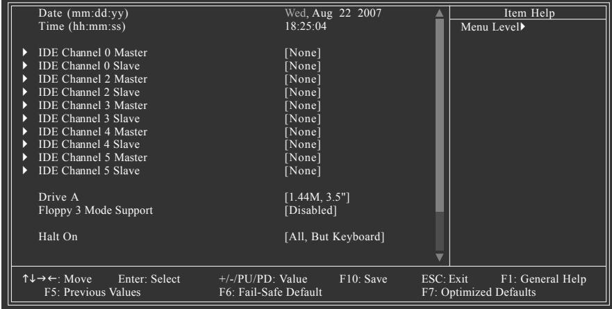
2-3 Standard CMOS Features
CMOS Setup Utility-Copyright (C) 1984-2007 Award Software Standard CMOS Features
text_image
Date (mm:dd:yy) Wed, Aug 22 2007 Time (hh:mm:ss) 18:25:04 ► IDE Channel 0 Master [None] ► IDE Channel 0 Slave [None] ► IDE Channel 2 Master [None] ► IDE Channel 2 Slave [None] ► IDE Channel 3 Master [None] ► IDE Channel 3 Slave [None] ► IDE Channel 4 Master [None] ► IDE Channel 4 Slave [None] ► IDE Channel 5 Master [None] ► IDE Channel 5 Slave [None] Drive A [1.44M, 3.5"] Floppy 3 Mode Support [Disabled] Halt On [All, But Keyboard] ↑↓→←: Move Enter: Select +/-/PU/PD: Value F10: Save ESC: Exit F1: General Help F5: Previous Values F6: Fail-Safe Default F7: Optimized DefaultsCMOS Setup Utility-Copyright (C) 1984-2007 Award Software Standard CMOS Features
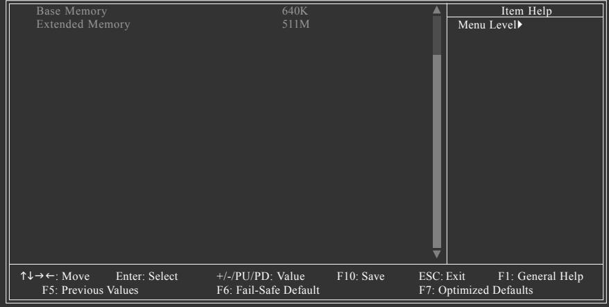
text_image
Base Memory 640K Extended Memory 511M ↑↓→←: Move Enter: Select +/-/PU/PD: Value F10: Save ESC: Exit F1: General Help F5: Previous Values F6: Fail-Safe Default F7: Optimized Defaults Item Help Menu Level▶Date
Sets the system date. The date format is week (read-only), month, date and year. Select the desired field and use the up arrow or down arrow key to set the date.
Time
Sets the system time. For example, 1 p.m. is 13:0:0. Select the desired field and use the up arrow or down arrow key to set the time.
IDE Channel 0 Master/Slave
▶ IDE HDD Auto-Detection
Press
▶ IDE Channel 0 Master/Slave
Configure your IDE/SATA devices by using one of the three methods below:
- Auto Lets BIOS automatically detect IDE/SATA devices during the POST. (Default)
- None If no IDE/SATA devices are used, set this item to None so the system will skip the detection of the device during the POST for faster system startup.
- Manual Allows you to manually enter the specifications of the hard drive when the hard drive access mode is set to CHS.
▶ Access Mode Sets the hard drive access mode. Options are: Auto (default), CHS, LBA, Large.
IDE Channel 2, 3, 4, 5 Master/Slave
▶▶ IDE Auto-Detection
Press
▶ Extended IDE Drive Configure your IDE/SATA devices by using one of the two methods below:
- Auto
- None
Lets BIOS automatically detect IDE/SATA devices during the POST. (Default)
If no IDE/SATA devices are used, set this item to None so the system will skip the detection of the device during the POST for faster system startup.
▶ Access Mode Sets the hard drive access mode. Options are: Auto (default), Large.
The following fields display your hard drive specifications. If you wish to enter the parameters manually, refer to the information on the hard drive.
▶ Capacity Approximate capacity of the currently installed hard drive.
▶ Cylinder Number of cylinders.
▶▶ Head Number of heads.
▶ Precomp Write precompensation cylinder.
▶ Landing Zone Landing zone.
▶ Sector Number of sectors.
Drive A
Allows you to selects the type of floppy disk drive installed in your system. If you do not install a floppy disk drive, set this item to None. Options are: None, 360K/5.25", 1.2M/5.25", 720K/3.5", 1.44M/3.5", 2.88M/3.5".
Floppy 3 Mode Support
Allows you to specify whether the installed floppy disk drive is 3-mode floppy disk drive, a Japanese standard floppy disk drive. Options are: Disabled (default), Drive A.
Halt on
Allows you to determine whether the system will stop for an error during the POST.
▶ No Errors The system boot will not stop for any error.
▶ All Errors Whenever the BIOS detects a non-fatal error the system boot will stop.
▶ All, But Keyboard The system boot will not stop for a keyboard error but stop for all other errors. (Default)
▶ All, But Diskette The system boot will not stop for a floppy disk drive error but stop for all other errors.
▶ All, But Disk/Key The system boot will not stop for a keyboard or a floppy disk drive error but it will stop for all other errors.
Memory
These fields are read-only and are determined by the BIOS POST.
Base Memory Also called conventional memory. Typically, 640 KB will be reserved for the MS-DOS operating system.
▶ Extended Memory The amount of extended memory.
2-4 Advanced BIOS Features
CMOS Setup Utility-Copyright (C) 1984-2007 Award Software Advanced BIOS Features
| VirtualizationAMD K8 Cool&Quiet control▶ Hard Disk Boot PriorityFirst Boot DeviceSecond Boot DeviceThird Boot DevicePassword CheckHDD S.M.A.R.T. CapabilityAway ModeInit Display First | [Disabled][Auto][Press Enter][Floppy][Hard Disk][CDROM][Setup][Disabled][Disabled][PCI Slot] | Item Help |
| Menu Level▶ | ||
| ↑↓→←: Move Enter: Select +/-/PU/PD: Value F10: Save ESC: Exit F1: General HelpF5: Previous Values F6: Fail-Safe Defaults F7: Optimized Defaults | ||
Virtualization
Virtualization allows a platform to run multiple operating systems and applications in independent partitions. With virtualization, one computer system can function as multiple virtual systems. (Default: Disabled)
AMD K8 Cool&Quiet control
▶ Auto Lets the AMD Cool'n'Quiet driver dynamically adjust the CPU clock and VIA to reduce heat output from your computer and its power consumption. (Default)
▶ Disabled Disables this function.
Hard Disk Boot Priority
Specifies the sequence of loading the operating system from the installed hard drives. Use the up or down arrow key to select a hard drive, then press the plus key <+> (or
First/Second/Third Boot Device
Specifies the boot order from the available devices. Use the up or down arrow key to select a device and press
Password Check
Specifies whether a password is required every time the system boots, or only when you enter BIOS Setup. After configuring this item, set the password(s) under the Set Supervisor/User Password item in the BIOS Main Menu.
▶ Setup A password is only required for entering the BIOS Setup program. (Default)
▶ System A password is required for booting the system and for entering the BIOS Setup program.
HDD S.M.A.R.T. Capability
Enables or disables the S.M.A.R.T. (Self Monitoring and Reporting Technology) capability of your hard drive. This feature allows your system to report read/write errors of the hard drive and to issue warnings when a third party hardware monitor utility is installed. (Default: Disabled)
Away Mode
Enables or disables Away Mode in Windows XP Media Center operating system. Away Mode allows the system to silently perform unattended tasks while in a low-power mode that appears off (Default: Disabled)
Init Display First
Specifies the first initiation of the monitor display from the installed PCI graphics card or PCI Express graphics card.
▶ PCI Slot Sets the PCI graphics card as the first display. (Default)
▶ PEG Sets the PCI Express graphics card on the PCIE_16_A slot as the first display.
▶ PEG1 Sets the PCI Express graphics card on the PCIE_16_B slot as the first display.
2-5 Integrated Peripherals
| ►IDE Configuration OnChip SATA Controller OnChip SATA Type ►OnBoard PCIE Device Onboard Audio Function Onboard 1394 Function OnChip USB Controller USB EHCI Controller USB Keyboard Support USB Mouse Support Legacy USB storage detect Onboard Serial Port 1 Onboard Parallel Port Parallel Port Mode x ECP Mode Use DMA | [Press Enter] [Enabled] [Native IDE] [Press Enter] [Auto] [Enabled] [Enabled] [Disabled] [Disabled] [Enabled] [3F8/IRQ4] [378/IRQ7] [SPP] 3 | Item Help |
| Menu Level▶ | ||
| ↑↓→←: Move Enter: Select +/-/PU/PD: Value F10: Save ESC: Exit F1: General Help F5: Previous Values F6: Fail-Safe Defaults F7: Optimized Defaults | ||
IDE Configuration
| OnChip IDE Channel0 | [Enabled] | Item Help |
| Menu Level▶ | ||
| ↑↓→←: Move Enter: Select +/-/PU/PD: Value F10: Save ESC: Exit F1: General Help F5: Previous Values F6: Fail-Safe Defaults F7: Optimized Defaults | ||
OnChip IDE Channel0
Enables or disables the integrated IDE controller. (Default: Enabled)
OnChip SATA Controller (AMD SB600 chip)
Enables or disables the integrated SATA controller. (Default: Enabled)
OnChip SATA Type (AMD SB600 chip)
Configures the operating mode of the integrated SATA controller.
▶ Native IDE Allows the SATA controller to operate in Native IDE mode. (Default) Enable Native IDE mode if you wish to install operating systems that support Native mode, e.g. Windows XP/2000.
▶ RAID Enables RAID for the SATA controller.
▶ Legacy IDE Allows the SATA controller to operate in Legacy IDE mode. In Legacy mode the SATA controller uses dedicated IRQs that cannot be shared with other device. Set this option to Legacy IDE if you wish to install operating systems that do not support Native mode, e.g. Windows 9X/ME
▶ SATA ->AHCI Configures the SATA controller to AHCI mode. Advanced Host Controller Interface (AHCI) is an interface specification that allows the storage driver to enable advanced Serial ATA features such as Native Command Queuing and hot plug. For more information about AHCI, please visit Intel's website.
OnBoard PCIE Device
| Onboard LAN Function [Enabled] Onboard LAN Boot ROM [Disabled] SMART LAN [Press Enter] Onboard ESATA-II Ctrl [Enabled] Onboard ESATA-II Ctrl Mode [IDE] Onboard GSATA-II Ctrl [Enabled] Onboard GSATA-II Ctrl Mode [IDE] | Item Help |
| Menu Level▶ | |
| ↑↓→←: Move Enter: Select +/-/PU/PD: Value F10: Save ESC: Exit F1: General Help F5: Previous Values F6: Fail-Safe Defaults F7: Optimized Defaults | |
Onboard LAN Function
Enables or disables the onboard LAN function. (Default: Enabled)
If you wish to install a 3rd party add-in network card instead of using the onboard LAN, set this item to Disabled.
Onboard LAN Boot ROM
Allows you to decide whether to activate the boot ROM integrated with the onboard LAN chip.
(Default: Disabled)
SMART LAN (LAN Cable Diagnostic Function)
| Start detecting at Port..... | Item Help | |||||
| Pair1-2 Status = Open / Length = 0.0m | Menu Level▶ | |||||
| Pair3-6 Status = Open / Length = 0.0m | ||||||
| Pair4-5 Status = Open / Length = 0.0m | ||||||
| Pair7-8 Status = Open / Length = 0.0m | ||||||
| ↑↓→←: Move Enter: Select +/-/PU/PD: Value F10: Save ESC: Exit F1: General Help F5: Previous Values F6: Fail-Safe Defaults F7: Optimized Defaults | ||||||
This motherboard incorporates cable diagnostic feature designed to detect the status of the attached LAN cable. This feature will detect cabling issue and report the approximate distance to the fault or short. Refer to the following information for diagnosing your LAN cable:
When No LAN Cable Is Attached...
If no LAN cable is attached to the motherboard, the Status fields of all four pairs of wires will show Open and the Length fields show 0.0m, as shown in the figure above.
When LAN Cable Is Functioning Normally...
If no cable problem is detected on the LAN cable connected to a Gigabit hub or a 10/100 Mbps hub, the following message will appear:
Start detecting at Port..... Link Detected --> 100Mbps Cable Length= 30m
▶ Link Detected Displays transmission speed
▶ Cable Length Displays the approximate length of the attached LAN cable.
Note: The Gigabit hub will only operate at a speed of 10/100Mbps in MS-DOS mode; it will operate at a normal speed of 10/100/1000Mbps in Windows mode or when the LAN Boot ROM is activated.
When a Cable Problem Occurs...
If a cable problem occurs on a specified pair of wires, the Status field will show Short and thenlength shown will be the approximate distance to the fault or short.
Example: Pair1-2 Status = Short / Length = 1.6m
Explanation: A fault or short might occur at about 1.6m on Pair 1-2.
Note: Pair 4-5 and Pair 7-8 are not used in a 10/100 Mbps environment, so their Status fields will show Open, and the length shown is the approximate length of the attached LAN cable.
Onboard ESATA-II Ctrl (GIGABYTE SATA2 Chip, eSATA 3Gb/s ports)
Enables or disables the SATA controller integrated in the GIGABYTE SATA 2 chip. (Default: Enabled)
Onboard ESATA-II Ctrl Mode (GIGABYTE SATA2 Chip, eSATA 3Gb/s ports)
Enables or disables RAID for the SATA controller integrated in the GIGABYTE SATA 2 chip or configures the SATA controller to AHCI mode.
| IDE | Disables RAID for the SATA controller and configures the SATA controller to PATA mode. (Default) |
| AHCI | Configures the SATA controller to AHCI mode. Advanced Host Controller Interface (AHCI) is an interface specification that allows the storage driver to enable advanced Serial ATA features such as Native Command Queuing and hot plug. |
| RAID | Enables RAID for the SATA controller. |
Onboard GSATA-II Ctrl (GIGABYTE SATA2 Chip, GSATAII_1/GSATAII_2 connectors)
Enables or disables the SATA controller integrated in the GIGABYTE SATA 2 chip. (Default: Enabled)
Onboard GSATA-II Ctrl Mode (GIGABYTE SATA2 Chip, GSATAII_1/GSATAII_2 connectors)
Enables or disables RAID for the SATA controller integrated in the GIGABYTE SATA 2 chip or configures the SATA controller to AHCI mode.
| IDE | Disables RAID for the SATA controller and configures the SATA controller to PATA mode. (Default) |
| AHCI | Configures the SATA controller to AHCI mode. Advanced Host Controller Interface (AHCI) is an interface specification that allows the storage driver to enable advanced Serial ATA features such as Native Command Queuing and hot plug. |
| RAID | Enables RAID for the SATA controller. |
Onboard Audio Function
Enables or disables the onboard audio function. (Default: Auto)
If you wish to install a 3rd party add-in audio card instead of using the onboard audio, set this item to Disabled.
Onboard 1394 Function
Enables or disables the onboard IEEE 1394 function. (Default: Enabled)
OnChip USB Controller
Enables or disables the integrated USB 1.1 controller. (Default: Enabled)
USB EHCI Controller
Enables or disables the integrated USB 2.0 controller. (Default: Enabled)
USB Keyboard Support
Allows USB keyboard to be used in MS-DOS. (Default: Disabled)
USB Mouse Support
Allows USB mouse to be used in MS-DOS. (Default: Disabled)
Legacy USB storage detect
Determines whether to detect USB storage devices, including USB flash drives and USB hard drives during the POST. (Default: Enabled)
Onboard Serial Port 1
Enables or disables the first serial port and specifies its base I/O address and corresponding interrupt. Options are: Auto, 2F8/IRQ3, 3F8/IRQ4(default), 3E8/IRQ4, 2E8/IRQ3, Disabled.
Onboard Parallel Port
Enables or disables the onboard parallel port (LPT) and specifies its base I/O address and corresponding interrupt. Options are: 378/IRQ7 (default), 278/IRQ5, 3BC/IRQ7, Disabled.
Parallel Port Mode
Selects an operating mode for the onboard parallel (LPT) port. Options are: SPP (Standard Parallel Port)(default), EPP (Enhanced Parallel Port), ECP (Extended Capabilities Port), ECP+EPP.
ECP Mode Use DMA
Selects DMA channel for the LPT port in ECP mode. This item is configurable only if Parallel Port Mode is set to ECP or ECP+EPP mode. Options are: 3 (default), 1.
2-6 Power Management Setup
CMOS Setup Utility-Copyright (C) 1984-2007 Award Software Power Management Setup
| ACPI Suspend Type | [S1(POS)] | Item Help |
| Soft-Off by Power button | [Instant-off] | Menu Level▶ |
| Modem Ring Resume | [Disabled] | |
| USB Wake Up from S3 | [Enabled] | |
| PME Event Wake Up | [Disabled] | |
| HPET Support (Note) | [Enabled] | |
| Power On By Mouse | [Disabled] | |
| Power On By Keyboard | [Disabled] | |
| x KB Power ON Password | Enter | |
| AC Back Function | [Soft-Off] | |
| Power-On by Alarm | [Disabled] | |
| x Date (of Month) | Everyday | |
| x Resume Time (hh:mm:ss) | 0:0:0 |
ACPI Suspend Type
Specifies the ACPI sleep state when the system enters suspend.
▶ S1(POS) Enables the system to enter the ACPI S1 (Power on Suspend) sleep state (default). In S1 sleep state, the system appears suspended and stays in a low power mode. The system can be resumed at any time.
▶ S3(STR) Enables the system to enter the ACPI S3 (Suspend to RAM) sleep state. In S3 sleep state, the system appears to be off and consumes less power than in the S1 state. When signaled by a wake-up device or event, the system resumes to its working state exactly where it was left off.
Soft-Off by Power button
Configures the way to turn off the computer in MS-DOS mode using the power button.
▶ Instant-Off Press the power button and then the system will be turned off instantly. (Default)
▶ Delay 4 Sec. Press and hold the power button for 4 seconds to turn off the system. If the power button is pressed for less than 4 seconds, the system will enter suspend mode.
Modem Ring Resume
Allows the system to be awakened from an ACPI sleep state by a wake-up signal from a modem that supports wake-up function. (Default: Disabled)
USB Wake Up from S3
Allows the system to be awakened from ACPI S3 sleep state by a wake-up signal from the installed USB device. (Default: Enabled)
(Note) Supported on Windows® Vista® operating system only.
PME Event Wake Up
Allows the system to be awakened from an ACPI sleep state by a wake-up signal from a PCI or PCIe device. Note: To use this function, you need an ATX power supply providing at least 1A on the +5VSB lead. (Default: Disabled)
HPET Support (Note)
Enables or disables High Precision Event Timer (HPET) for Windows® Vista® operating system. (Default: Enabled)
Power On By Mouse
Allows the system to be turned on by a PS/2 mouse wake-up event.
Note: To use this function, you need an ATX power supply providing at least 1A on the +5VSB lead.
▶ Disabled Disables this function. (Default)
▶ Double Click Double click on left button on the PS/2 mouse to turn on the system.
Power On By Keyboard
Allows the system to be turned on by a PS/2 keyboard wake-up event.
Note: you need an ATX power supply providing at least 1A on the +5VSB lead.
▶ Disabled Disables this function. (Default)
▶ Password Set a password with 1\~5 characters to turn on the system.
▶ Any KEY Press any key on the keyboard to turn on the system.
▶ Keyboard 98 Press POWER button on the Windows 98 keyboard to turn on the system.
KB Power ON Password
Set the password when Power On by Keyboard is set to Password. Press
Note: To cancel the password, press
AC Back Function
Determines the state of the system after the return of power from an AC power loss.
▶ Soft-Off The system stays off upon the return of the AC power. (Default)
▶ Full-On The system is turned on upon the return of the AC power.
▶ Memory The system returns to its last known awake state upon the return of the AC power.
Power-On by Alarm
Determines whether to power on the system at a desired time. (Default: Disabled)
If enabled, set the date and time as following:
▶ Date (of Month): Turn on the system at a specific time on each day or on a specific day in a month.
Resume Time (hh: mm: ss): Set the time at which the system will be powered on automatically.
Note: When using this function, avoid inadequate shutdown from the operating system or removal of the AC power, or the settings may not be effective.
(Note) Supported on Windows® Vista® operating system only.
2-7 PnP/PCI Configurations
| PCI1 IRQ Assignment [Auto] PCI2 IRQ Assignment [Auto] | Item Help |
| Menu Level▶ | |
| ↑↓→←: Move Enter: Select +/-/PU/PD: Value F10: Save ESC: Exit F1: General Help F5: Previous Values F6: Fail-Safe Defaults F7: Optimized Defaults | |
PCI1 IRQ Assignment
▶ Auto BIOS auto-assigns IRQ to the first PCI slot. (Default)
▶ 3,4,5,7,9,10,11,12,14,15 Assigns IRQ 3,4,5,7,9,10,11,12,14,15 to the first PCI slot.
PCI2 IRQ Assignment
▶ Auto BIOS auto-assigns IRQ to the second PCI slot. (Default)
▶ 3,4,5,7,9,10,11,12,14,15 Assigns IRQ 3,4,5,7,9,10,11,12,14,15 to the second PCI slot.
2-8 PC Health Status
CMOS Setup Utility-Copyright (C) 1984-2007 Award Software PC Health Status
| Reset Case Open Status | [Disabled] | Item Help | |
| Case Opened | No | Menu Level▶ | |
| Vcore | 1.376V | ||
| DDR2 1.8V | 1.872V | ||
| +3.3V | 3.328V | ||
| +12V | 12.112V | ||
| Current System Temperature | 30℃ | ||
| Current CPU Temperature | 47℃ | ||
| Current CPU FAN Speed | 3375 RPM | ||
| Current SYSTEM FAN1 Speed | 0 RPM | ||
| Current SYSTEM FAN2 Speed | 0 RPM | ||
| Current POWER FAN Speed | 0 RPM | ||
| CPU Warning Temperature | [Disabled] | ||
| CPU FAN Fail Warning | [Disabled] | ||
| SYSTEM FAN1 Fail Warning | [Disabled] | ||
| SYSTEM FAN2 Fail Warning | [Disabled] | ||
| POWER FAN Fail Warning | [Disabled] | ||
| CPU Smart FAN Control | [Enabled] | ||
| CPU Smart FAN Mode | [Auto] | ||
| ↑↓→←: Move Enter: Select +/-/PU/PD: Value F10: Save ESC: Exit F1: General Help F5: Previous Values F6: Fail-Safe Defaults F7: Optimized Defaults | |||
CMOS Setup Utility-Copyright (C) 1984-2007 Award Software PC Health Status
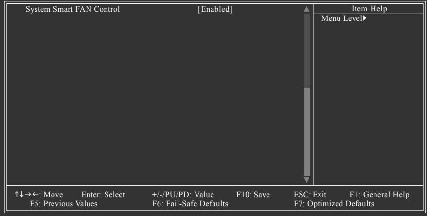
flowchart
graph TD
    A["System Smart FAN Control"] --> B["↑↓→←: Move"]
    B --> C["Enter: Select"]
    C --> D["+/-/PU/PD: Value"]
    D --> E["F10: Save"]
    E --> F["ESC: Exit"]
    F --> G["F1: General Help"]
    G --> H["F7: Optimized Defaults"]
    I["Item Help"] --> J["Menu Level▶"]
Reset Case Open Status
Keeps or clears the record of previous chassis intrusion status. Enabled clears the record of previous chassis intrusion status and the Case Opened field will show "No" at next boot. (Default: Disabled)
Case Opened
Displays the detection status of the chassis intrusion detection device attached to the motherboard CI header. If the system chassis cover is removed, this field will show "Yes", otherwise it will show "No". To clear the chassis intrusion status record, set Reset Case Open Status to Enabled, save the settings to CMOS, and then restart your system.
Current Voltage(V) Vcore/DDR2 1.8V/+3.3V/+12V
Displays the current system voltages.
Current System/CPU Temperature
Displays current system/CPU temperature.
Current CPU/SYSTEM/POWER FAN Speed (RPM)
Displays current CPU/system/power fan speed.
CPU Warning Temperature
Sets the warning threshold for CPU temperature. When CPU temperature exceeds the threshold, BIOS will emit warning sound. Options are: Disabled (default), 60°C/140°F, 70°C/158°F, 80°C/176°F, 90°C/194°F.
CPU/SYSTEM/POWER FAN Fail Warning
Allows the system to emit warning sound if the CPU/system/power fan is not connected or fails. Check the fan condition or fan connection when this occurs. (Default: Disabled)
CPU Smart FAN Control
Enables or disables the CPU fan speed control function. Enabled allows the CPU fan to run at different speed according to the CPU temperature. You can adjust the fan speed with EasyTune based on system requirements. If disabled, CPU fan runs at full speed. (Default: Enabled)
CPU Smart FAN Mode
Specifies how to control CPU fan speed. This item is configurable only if CPU Smart FAN Control is set to Enabled.
▶ Auto Lets BIOS autodetect the type of CPU fan installed and sets the optimal CPU fan control mode. (Default)
▶ Voltage Sets Voltage mode for a 3-pin CPU fan.
▶ PWM Sets PWM mode for a 4-pin CPU fan.
System Smart FAN Control
Enables or disables the system fan speed control function. Enabled allows the system fan to run at different speed according to the system temperature. You can adjust the fan speed with EasyTune based on system requirements. If disabled, system fan runs at full speed. (Default: Enabled)
2-9 MB Intelligent Tweaker(M.I.T.)
CMOS Setup Utility-Copyright (C) 1984-2007 Award Software MB Intelligent Tweaker(M.I.T.)
| CPU Clock Ratio | [Auto] | Item Help |
| CPU Host Clock Control | [Auto] | Menu Level▶ |
| x CPU Frequency (MHz) | 200 | |
| HT Link Frequency | [Auto] | |
| PCIE Clock (MHz) | [Auto] | |
| Set Memory Clock | [Auto] | |
| x Memory Clock | DDR 533 | |
| DRAM Configuration | [Press Enter] | |
| ******** System Voltage Optimized ******** | ||
| System Voltage Control | [Manual] | |
| CPU Voltage Control | [Normal] | |
| Normal CPU Veore | 1.3500V | |
| DDR2 Voltage Control | [Normal] | |
| Chipset Voltage Control | [Normal] | |
| PCIE Voltage Control | [Normal] | |
| HTT Voltage Control | [Normal] | |
| HTR Voltage Control | [Normal] | |
| ↑↓→←: Move Enter: Select +/-PU/PD: Value F10: Save ESC: Exit F1: General Help F5: Previous Values F6: Fail-Safe Defaults F7: Optimized Defaults | ||

- Incorrectly doing overclock/overvoltage may result in damage to CPU, chipset, or memory and reduce the useful life of these components. This page is for advanced users only and we recommend you not to alter the default settings to prevent system instability or other unexpected results. (Inadequately altering the settings may result in system's failure to boot. If this occurs, clear the CMOS values and reset the board to default values.)
- When the System Voltage Optimized item blinks in red, it is recommended that you set the System Voltage Control item to Auto to optimize the system voltage settings.
CPU Clock Ratio
Allows you to alter the clock ratio for the installed CPU. The adjustable range is dependent on the CPU being used.
CPU Host Clock Control
Enables or disables the control of CPU host clock. Auto (default) allows BIOS to automatically adjust the CPU host frequency. Manual allows the CPU Frequency (Mhz) item below to be configurable. Note: If your system fails to boot after overclocking, please wait for 20 seconds to allow for automated system reboot, or clear the CMOS values to reset the board to default values.
CPU Frequency (MHz)
Allows you to manually set the CPU host frequency.
The adjustable range is from 200 MHz to 500 MHz
Important It is highly recommended that the CPU frequency be set in accordance with the CPU specifications.
HT Link Frequency
Allows you to manually set the frequency for the HT Link between the CPU and chipset.
Auto lets BIOS automatically set the HT Link frequency as required. Options are: Auto (default), 200 MHz, 400 MHz, 600 MHz, 800 MHz, 1 GHz.
PCIE Clock (MHz)
Allows you to manually set the PCIe clock frequency. The adjustable range is from 100 MHz to 200 MHz. Auto sets the PCIe clock frequency to standard 100 MHz. (Default: Auto)
Set Memory Clock
Determines whether to manually set the memory clock. Auto lets BIOS automatically set the memory clock as required. Manual allows the memory clock control item below to be configurable. (Default: Auto)
Memory Clock
This option is configurable only when Set Memory Clock is set to Manual. Options are: DDR 400, DDR 533, DDR 667, DDR 800.
DRAM Configuration
| DDRII Timing Items [Auto] | Item Help | |||
| x CAS# latency 4T | Menu Level▶ | |||
| x 1T/2T Command Timing 1T | ||||
| x TwTr Command Delay 2T | ||||
| x Write Recovery Time 4T | ||||
| x Precharge Time 2T | ||||
| x Row Cycle Time 17T | ||||
| x RAS to CAS R/W Delay 4T | ||||
| x RAS to RAS Delay 2T | ||||
| x Row Precharge Time 4T | ||||
| x Minimum RAS Active Time 12T | ||||
| ↑↓→←: Move Enter: Select +/-/PU/PD: Value F10: Save ESC: Exit F1: General Help F5: Previous Values F6: Fail-Safe Defaults F7: Optimized Defaults | ||||
DDRII Timing Items
Manual allows all DDRII Timing items below to be configurable.
Options are: Auto (default), Manual.
CAS# latency
Options are: 3T, 4T (default), 5T, 6T.
1T/2T Command Timing
Options are: 1T (default), 2T.
TwTr Command Delay
Options are: 1T, 2T (default), 3T.
Write Recovery Time
Options are: 3T, 4T (default), 5T, 6T.
Precharge Time
Options are: 2T (default), 3T.
Row Cycle Time
Options are: 11T\~26T. (Default: 17T)
RAS to CAS R/W Delay
Options are: 3T, 4T (default), 5T, 6T.
RAS to RAS Delay
Options are: 2T (default), 3T, 4T, 5T.
Row Precharge Time
Options are: 3T, 4T (default), 5T, 6T.
Minimum RAS Active Time
Options are: 5T\~18T. (Default: 12T)
System Voltage Control
Determines whether to manually set the system voltages. Auto lets BIOS automatically set the system voltages as required. Manual allows all voltage control items below to be configurable. (Default: Manual)
CPU Voltage Control
Allows you to set the CPU voltage. Normal sets the CPU voltage as required. The adjustable range is dependent on the CPU being installed. (Default: Normal)
Note: Increasing CPU voltage may result in damage to your CPU or reduce the useful life of the CPU.
Normal CPU Vcore
Displays the normal operating voltage of your CPU.
DDR2 Voltage Control
Allows you to to set memory voltage.
▶ Normal Supplies the memory voltage as required. (Default)
▶ +0.05V \~ +0.50V Increases memory voltage by 0.05V to 0.50V at 0.05V increment.
Chipset Voltage Control
Allows you to set the Chipset voltage.
▶ Normal Supplies the Chipset voltage as required. (Default)
▶ +0.05V \~ +0.40V Increases Chipset voltage by 0.05V to 0.40V at 0.05V increment.
PCIE OverVoltage Control
Allows you to to set PCIe voltage.
▶ Normal Supplies the PCIe bus voltage as required. (Default)
▶ +0.05V \~ +0.45V Increases PCIe bus voltage by 0.05V to 0.45V at 0.05V increment.
HTT Voltage Control
Allows you to to set Hyper Transport Transmit voltage.
▶ Normal Supplies the Hyper Transport Transmit voltage as required. (Default)
▶ +0.05V \~ +0.40V Increases Hyper Transport Transmit voltage by 0.05V to 0.40V at 0.05V increment.
HTR OverVoltage Control
Allows you to to set Hyper Transport Receive voltage.
▶ Normal Supplies the Hyper Transport Receive voltage as required. (Default)
▶ +0.05V \~ +0.45V Increases Hyper Transport Receive voltage by 0.05V to 0.45V at 0.05V increment.
2-10 Load Fail-Safe Defaults
CMOS Setup Utility-Copyright (C) 1984-2007 Award Software
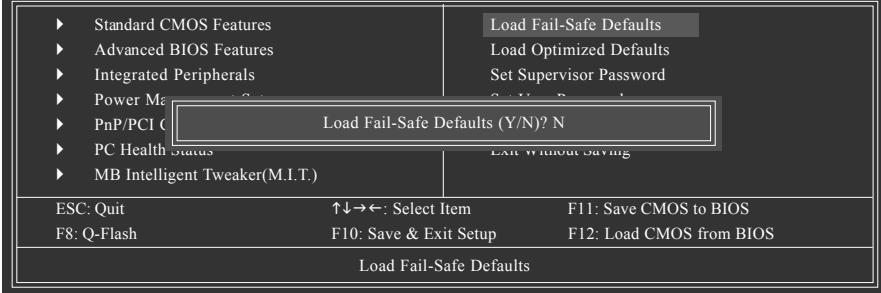
text_image
Standard CMOS Features Advanced BIOS Features Integrated Peripherals Power Ma PnP/PCI (C) PC Health Status MB Intelligent Tweaker(M.I.T.) Load Fail-Safe Defaults Load Fail-Safe Defaults Load Optimized Defaults Set Supervisor Password Load Fail-Safe Defaults (Y/N)? N Exit Without Saving ESC: Quit ↑↓→←: Select Item F11: Save CMOS to BIOS F8: Q-Flash F10: Save & Exit Setup F12: Load CMOS from BIOS Load Fail-Safe DefaultsPress
2-11 Load Optimized Defaults
CMOS Setup Utility-Copyright (C) 1984-2007 Award Software
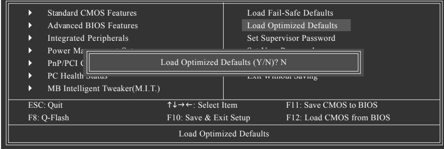
text_image
Standard CMOS Features Advanced BIOS Features Integrated Peripherals Power Ma PnP/PCI (Y/N)? N PC Health Status MB Intelligent Tweaker(M.I.T.) Load Fail-Safe Defaults Load Optimized Defaults Set Supervisor Password Load Optimized Defaults (Y/N)? N Exit Without Saving ESC: Quit F8: Q-Flash ↑↓→←: Select Item F10: Save & Exit Setup F11: Save CMOS to BIOS F12: Load CMOS from BIOS Load Optimized DefaultsPress
2-12 Set Supervisor/User Password
CMOS Setup Utility-Copyright (C) 1984-2007 Award Software
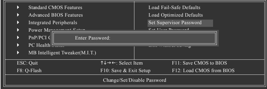
text_image
Standard CMOS Features Advanced BIOS Features Integrated Peripherals Power Management Setup PnP/PCI (Enter Password: PC Health Status MB Intelligent Tweaker(M.I.T.) Load Fail-Safe Defaults Load Optimized Defaults Set Supervisor Password Set User Password ESC: Quit ↑↓→←: Select Item F11: Save CMOS to BIOS F8: Q-Flash F10: Save & Exit Setup F12: Load CMOS from BIOS Change/Set/Disable PasswordPress
The BIOS Setup program allows you to specify two separate passwords:
Supervisor Password
When a system password is set and the Password Check item in Advanced BIOS Features is set to Setup, you must enter the supervisor password for entering BIOS Setup and making BIOS changes.
When the Password Check item is set to System, you must enter the supervisor password (or user password) at system startup and when entering BIOS Setup.
User Password
When the Password Check item is set to System, you must enter the supervisor password (or user password) at system startup to continue system boot. In BIOS Setup, you must enter the supervisor password if you wish to make changes to BIOS settings. The user password only allows you to view the BIOS settings but not to make changes.
To clear the password, press
2-13 Save & Exit Setup
CMOS Setup Utility-Copyright (C) 1984-2007 Award Software
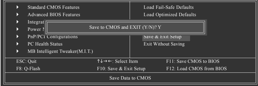
text_image
Standard CMOS Features Advanced BIOS Features Integrat Power M Save to CMOS and EXIT (Y/N)? Y PnP/PCI Configurations PC Health Status MB Intelligent Tweaker(M.I.T.) Save & Exit Setup Exit Without Saving ESC: Quit F8: Q-Flash ↑↓→←: Select Item F10: Save & Exit Setup F11: Save CMOS to BIOS F12: Load CMOS from BIOS Save Data to CMOSPress
2-14 Exit Without Saving
CMOS Setup Utility-Copyright (C) 1984-2007 Award Software
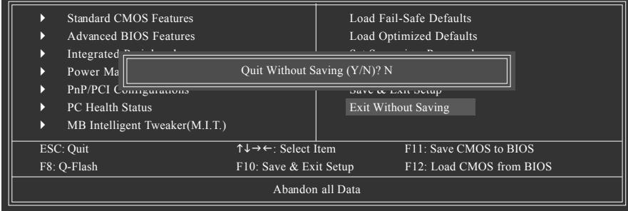
text_image
Standard CMOS Features Advanced BIOS Features Integrated BIOS Features Power Ma PnP/PCI Configurations PC Health Status MB Intelligent Tweaker(M.I.T.) Quit Without Saving (Y/N)? N Save & Exit Setup Exit Without Saving ESC: Quit F8: Q-Flash ↑↓→←: Select Item F10: Save & Exit Setup F11: Save CMOS to BIOS F12: Load CMOS from BIOS Abandon all DataPress
Chapter 3 Drivers Installation

- Before installing the drivers, first install the operating system. (The following instructions use Windows XP as the example operating system.)
- After installing the operating system, insert the motherboard driver disk into your optional drive. The driver Autorun screen is automatically displayed which looks like that shown in the screen shot below. (If the driver Autorun screen does not appear automatically, go to My Computer, double-click the optical drive and execute the Run.exe program.)
3-1 Installing Chipset Drivers
"Xpress Install " is now analyzing your computer...99%
After inserting the driver disk, "Xpress Install" will automatically scan the system and then list all the drivers that are recommended to install. Please select the item that you wish to install and press the Install button following the item. Or you can press Xpress Install to install all the driver items.
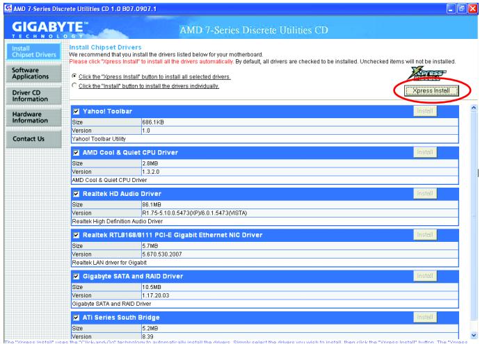
text_image
AMD 7-Series Discrete Utilities CD 1.0 B07.0907.1 GIGABYTE™ TECHNOLOGY AMD 7-Series Discrete Utilities CD Install Chipset Drivers We recommend that you install the drivers listed below for your motherboard. Please click "Xpress Install" to install all the drivers automatically. By default, all drivers are checked to be installed. Unchecked items will not be installed. Software Applications Click the "Xpress Install" button to install all selected drivers. Click the "Install" button to install the drivers individually. Driver CD Information Hardware Information Contact Us Yahoo! Toolbar Size 686.1KB Version 1.0 Yahoo! Toolbar Utility AMD Cool & Quiet CPU Driver Size 2.8MB Version 1.3.2.0 AMD Cool & Quiet CPU Driver Realtek HD Audio Driver Size 86.1MB Version R1.75-5.10.0.5473(XP)6.0.1.5473(MSTA) Realtek High Definition Audio Driver Realtek RTL8168/8111 PCI-E Gigabit Ethernet NIC Driver Size 5.7MB Version 5.670.530.2007 Realtek LAN driver for Gigabit Gigabyte SATA and RAID Driver Size 10.5MB Version 1.17.20.03 Oligabyte SATA and RAID Driver ATi Series South Bridge Size 5.2MB Version 8.39 Xpress Install
- Please ignore the popup dialog box(es) (e.g. the Found New Hardware Wizard) displayed when "Xpress Install" is installing the drivers. Failure to do so may affect the driver installation.
- Some device drivers will restart your system automatically during the driver installation. After the system restart, "Xpress Install" will continue to install other drivers.
- After the drivers are installed, follow the onscreen instructions to restart your system. You can install other applications included in the motherboard driver disk.
- For USB 2.0 driver support under the Windows XP operating system, please install the Windows XP Service Pack 1 or later. After installing the SP1 (or later), if a question mark still exists in Universal Serial Bus Controller in Device Manager, please remove the question mark (by right-clicking your mouse and select Uninstall) and restart the system. (The system will then autodetect and install the USB 2.0 driver.)
3-2 Software Applications
This page displays all the tools and applications that GIGABYTE develops and some free software. You may press the Install button following an item to install it.
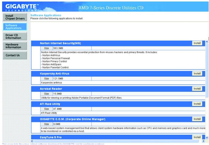
text_image
GIGABYTE TECHNOLOGY AMD 7-Series Discrete Utilities CD Install Chipset Drivers Software Applications Driver CD Information Hardware Information Contact Us Software Applications Please click the following applications to install. Norton Internet Security(NIS) Install Size 503.3MB Norton Internet Security provides essential protection from viruses hackers and privacy threats. It includes: - Norton Antivirus - Norton Personal Firewall - Norton Privacy Control - Norton AntiSpam - Norton Parental Control. Kaspersky Anti-Virus Install Size 121.5MB Kaspersky antivirus Acrobat Reader Install Size 15.9MB Utility for viewing or printing Adobe Portable Document Format (PDF) files. ATI Raid Utility Install Size 47.4MB ATI Raid Utility GIGABYTE C.O.M. (Corporate Online Manager) Install Size 9.0MB A web-based system management tool that allows client system hardware information such as CPU and memory and graphics card and much more to be monitored or controlled via a host. EasyTune 5 Pro Install3-3 Driver CD Information
This page provides information about the drivers, applications and tools in this driver disk.
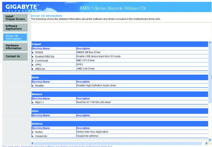
text_image
GIGABYTE TECHNOLOGY AMD 7-Series Discrete Utilities CD Driver CD Information The following shows the detailed information about the software and drivers included in the motherboard driver disk. Install Chipset Drivers Software Applications Driver CD Information Hardware Information Contact Us Chipset Directory Name Description • RS900 SB600 SM Bus Driver • EnableUSB33xp Enable USB device back form B3 mode • CoolQuiet AMD CPU Driver • XPR2 XPR2 • AMDLive -AMD Live Driver Audio Directory Name Description • Realtek Realtek High Definition Audio driver Network Directory Name Description • R8B111 RealTek 8111/R168 LAN driver Other Directory Name Description Antivirus Directory Name Description • Norton Norton Anti-Virus Application • Kaspersky Kaspersky antivirus3-4 Hardware Information
This page provides information about the hardware devices on this motherboard.
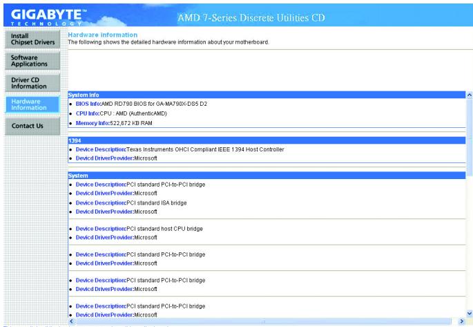
text_image
GIGABYTE™ TECHNOLOGY AMD 7-Series Discrete Utilities CD Install Chipset Drivers Hardware Information The following shows the detailed hardware information about your motherboard. Software Applications Driver CD Information Hardware Information Contact Us System Info • BIOS Info:AMD RD790 BIOS for GA-MA790X-DS5 D2 • CPU Info:CPU / AMD (AuthenticAMD) • Memory Info:522,872 KB RAM 1394 • Device Description:Texas Instruments OHCI Compliant IEEE 1394 Host Controller • Device DriverProvider:Microsoft System • Device Description:PCI standard PCI-to-PCI bridge • Device DriverProvider:Microsoft • Device Description:PCI standard ISA bridge • Device DriverProvider:Microsoft • Device Description:PCI standard host CPU bridge • Device DriverProvider:Microsoft • Device Description:PCI standard PCI-to-PCI bridge • Device DriverProvider:Microsoft • Device Description:PCI standard PCI-to-PCI bridge • Device DriverProvider:MicrosoftThis nano liete all the hardware components on this motherheart
3-5 Contact Us
Check the contacts information of the GIGABYTE headquarter in Taiwan and the overseas branch offices on the last page of this manual.
text_image
GIGABYTE™ AMD 7-Series Discrete Utilities CD GIGABYTE™ Contact Us Contact Us Install Chipset Drivers Software Applications Driver CD Information Hardware Information Contact Us GIGA-BYTE TECHNOLOGY CO.,LTD. ACI.B. Bus Chiang Kiyun Tian Tayapi Heian Taiyuan Tel: +628-2-691-2-4000 Fax: 668-2-6912-4000 http://www.gigabyte.com/td China (Office) Shanghai Tel: +95-021-62410399 Fax: +95-021-62410100 (8) China (Office) Beijing Tel: +95-010-82085051 Fax: +95-010-82085013 (8) China (Office) Guangzhou Tel: +95-020-87589376 Fax: +95-020-85517843 http://www.gigabyte.com/ China (Office) Zhejiang Tel: +95-026-87589300 Fax: +95-026-85517843 (8) China (Office) Shanghai Tel: +95-026-87589300 Fax: +95-026-85517843 U.S.A. B.F.T. INC. Tel: +1 (026) 054-9338 Fax: +1 (026) 054-9338 U.K. B.F.T. TECH. CO., LTD. Tel: +44-1909-362-100 Fax: +44-1909-362-100 Deyong B.F.T. TECHNOLOGY TRADING GMBH Tel: +43-40-2533040 (Sales) +43-1602-424661 (Tech.) Fax: +43-40-25452433 (Sales) +43-1602-424661 (Tech.) The Netherlands GIBA-BYTE TECHNOLOGY B.V. Tel: +31-40 290-2988 Nt. Tech Support - 0900-GIGABYTE (0900- 64422682) BTE Tech Support - 0900-84334 Fax: +31-40 290-2988 http://www.gigabyte.com/ http://www.gigabyte.com/ http://www.gigabyte.com/ http://www.gigabyte.com/ http://www.gigabyte.com/ http://www.gigabyte.com/ http://www.gigabyte.com/ http://www.gigabyte.com/ http://www.gigabyte.com/ http://www.gigabyte.com/ http://www.gigabyte.com/ http://www.gigabyte.com/ http://www.gigabyte.com/ http://www.bigabyte.com/ http://www.bigabyte.com/ http://www.bigabyte.com/ http://www.bigabyte.com/ http://www.bigabyte.com/ http://www.bigabyte.com/ http://www.bigabyte.com/ http://www.bigabyte.com/ http://www.bigabyte.com/ http://www.bigabyte.com/ http://www.bigabyte.com/ http://www.bigabyte.com/ http://www.bigabyte.com/Chapter 4 Unique Features
4-1 Xpress Recovery2

text_image
Xpress RECOVERYXpress Recovery2 is an utility that allows you to quickly compress and back up your system data and perform restoration of it. Supporting NTFS, FAT32, and FAT16 file systems, Xpress Recovery2 can back up data on PATA and SATA hard drives and restore it.
Before You Begin:
- Xpress Recovery2 will check the first physical hard drive* for the operating system. Xpress Recovery2 can only back up/restore the first physical hard drive that has the operating system installed.
- As Xpress Recovery2 will save the backup file at the end of the hard drive, make sure to leave enough unallocated space in advanced (10 GB or more is recommended; actual size requirements vary, depending on the amount of data).
- It is recommended to back up your system soon after the operating system and drivers are installed.
- The amount of data and hard drive access speed may affect the speed at which the data is backed up/restored.
- It takes longer to back up a hard drive than to restore it.
System Requirements:
- Intel® x86 platform
- At least 64 MB of system memory
• VESA compatible graphics card - Windows® 2000 with SP3 or later; Windows® XP with SP1 or later

- Xpress Recovery and Xpress Recovery2 are different utilities. For example, a backup file created with Xpress Recovery cannot be restored using Xpress Recovery2.
• USB hard drives are not supported. - Hard drives in RAID/AHCI mode are not supported.
"★"
Xpress Recovery2 checks the first physical hard drive in the following sequence: The first PATA IDE connector, the second PATA IDE connector, the first SATA connector, the second SATA connector and so forth. For example, when hard drives are attached to the first IDE and the first SATA connectors, the hard drive on the first IDE connector is the first physical drive. When hard drives are attached to the first and second SATA connectors, the hard drive on the first SATA connector is the first physical drive.
Installation and Configuration
(The following procedure uses Windows XP as the example operating system.)
A. Installing Windows XP and Partitioning the Hard Drive
- Set CD-ROM drive as the first boot device under "Advanced BIOS Features" in the BIOS Setup program. Save the changes and exit.
- When partitioning your hard drive (Figure 1), make sure to leave unallocated space for Xpress Recovery2 (10 GB or more is recommended; actual size requirements vary, depending on the amount of data) (Figure 2).
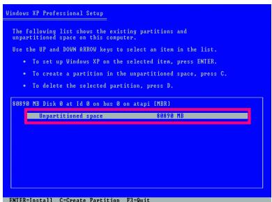
text_image
Windows XP Professional Setup The following list shows the existing partitions and unpartitioned space on this computer. Use the IP and DOWN AEROV keys to select an item in the list. • To set up Windows XP on the selected item, press ENTER. • To create a partition in the unpartitioned space, press C. • To delete the selected partition, press B. 8089B MD Disk @ at Id @ on bus @ on atapi [MBR1] Unpartitioned space 8089B MD ENTER=Install C=Create Partition P3=QuitFigure 1
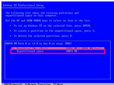
text_image
Windows XP Professional Setup The following list shows the existing partitions and unpartitioned space on this computer. Use the OP and DOWN ARROW keys to select an item in the list. • To set up Windows XP on the selected item, press ENTER. • To create a partition in the unpartitioned space, press C. • To delete the selected partition, press B. S8093B MD Disk 8 at Id 8 on bus 8 on atapi [MDB] Unpartitioned space S8092 MBFigure 2
- Select a file system (for example, NTFS) and begin the installation of the operating system (Figure 3).
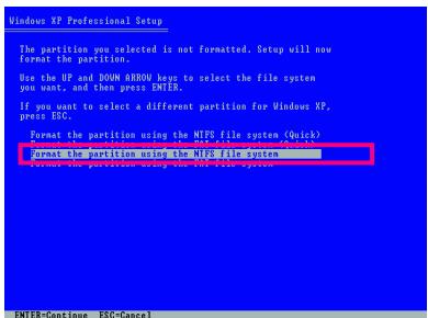
text_image
Windows XP Professional Setup The partition you selected is not formatted. Setup will now format the partition. Use the IP and DOWN AEROV key to select the file system you want, and then press ENTER. If you want to select a different partition for Windows XP, press ESC. Format the partition using the MIPS file system (Quick) Format the partition using the MIPS file system Format the partition using the MPI file system ENTER=Continue ESC-CancelFigure 3
- After the operating system is installed, right-click the My Computer icon on your desktop and select Manage (Figure 4). Go to Computer Management to check disk allocation. Xpress Recovery2 will save the backup file to the unallocated space (black stripe along the top)(Figure 5). Please note that if there is no enough unallocated space, Xpress Recovery2 cannot save the backup file.

text_image
Close Next Close Next Page Close Next Page Close Next Page Close Next Page Close Next Page Close Next Page Close Next Page Close Next Page Close Next Page Close Next Page Close Next Page Close Next Page Close Next Page Close Next Page Close Next Page Close Next Page Close Next Page Close Next Page Close Next Page Close Next Page Close Next Page Close Next Page Close Next Page Close Next Page Close Next Page Close Next Step Close Next Step Close Next Step Close Next Step Close Next Step Close Next Step Close Next Step Close Next Step Close Next Step Close Next Step Close Next Step Close Next Step Close Next Step Close Next Step Close Next Step Close Next Step Close Next Step Close Next Step Close Next Step Close Next Step Close Next Step Close Next Step Close Next Step Close Next Step Close Next Step Close Next Page Close Next Page Close Next Page Close Next Page Close Next Page Close Next Page Close Next Page Close Next Page Close Next Page Close Next Page Close Next Page Close Next Page Close Next Page Close Next Page Close Next Page Close Next Page Close Next Page Close Next Page Close Next Page Close Next Page Close Next Page Close Next Page Close Next Page Close Next Page Close Next DateFigure 4
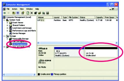
text_image
Computer Management File Action View Window Help Computer Management (Local) System Tools Event Viewer Shared folders Local Users and Groups Performance Logs and Alerts Device Manager Storage Renewable Storage Net Management Windows and Outlooks Apache Layout Type File System Status Capacity Free Space % (C:) Partition Base MIPS Healthy (System) 9.77 GB 7.04 GB NC (D:) (C:) (D)/GB 9.77 GB/MTFS 10.74 GB Online Healthy (System) Unallocated CD-ROMID DVD (D:) No Media Unallocated Primary portionFigure 5
- If your hard drive is not properly partitioned before you install the operating system, you may create new partitions using free space on your hard drive (Figure 6, 7). However, if Disk Management shows the hard drive only contains the System partition without any unallocated space, you will not be able to create new partitions or use Xpress Recovery2. If this occurs, reinstall the operating system and re-partition your hard drive.
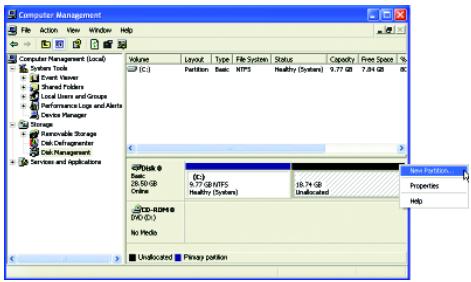
text_image
Computer Management File Action View Window Help Computer Management (Local) System Tools Event Viewer Financial Providers Local Users and Groups Performance Logs and Alerts Device Manager Storage Rearovable Storage Data Commitments Data Management Services and applications Volume Layout Type File System Status Capacity Free Space % (C:) Partition Basic NTFS Healthy Systems 9.77 GB 7.84 GB C:\Users\NTFS Healthy Systems\Unallocated New Portion Properties Help C:\Users\NTFS Healthy Systems\Unallocated D:\Windows\NTFS Healthy Systems No Media Unallocated Primary portionFigure 6
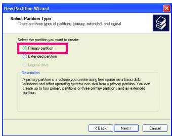
text_image
New Partition Wizard Select Partition Type There are three types of partitions: primary, extended, and logical. Select the partition you want to create: ○ Primary partition ○ Extended partition ○ Logical drive Description A primary partition is a volume you create using free space on a basic disk. Windows and other operating systems can start from a primary partition. You can create up to four primary partitions or three primary partitions and an extended partition. < Back Next > CancelFigure 7
In the New Partition Wizard, you MUST select Primary partition. This will reserve unallocated space for Xpress Recovery2 to use.
B. Accessing Xpress Recovery2
- Boot from the motherboard driver disk to access Xpress Recovery2 for the first time. When you see the following message: Press any key to startup Xpress Recovery2 (Figure 8), press any key to enter Xpress Recovery2.

text_image
. . Boot from CD/DVD: Press any key to startup XpressRecovery2.....Figure 8
- After you use the backup function in Xpress Recovery2 for the first time, Xpress Recovery2 will stay permanent in your hard drive. If you wish to enter Xpress Recovery2 later, simply press
during the POST (Figure 9).
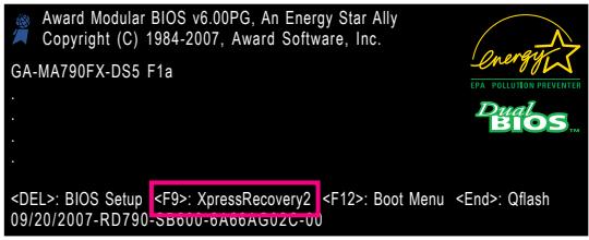
text_image
Award Modular BIOS v6.00PG, An Energy Star Ally Copyright (C) 1984-2007, Award Software, Inc. GA-MA790FX-DS5 F1a DEL>: BIOS SetupFigure 9
C. Using the Backup Function in Xpress Recovery2
- Select BACKUP to start backing up your hard drive data (Figure 10).
- Xpress Recovery2 will then begin to search the first physical hard drive as the target drive and detect whether this hard drive contains the Windows operating system. When the Windows operating system is detected, Xpress Recovery2 will begin the backup process (Figure 11).

text_image
GIGABYTE™ TECHNOLOGY Xpress2 RECOVERY Ver.1.01.060718 BACKUP REBOOT © Copyright 2008, GIGABYTE Technology Co., Ltd.Figure 10
text_image
GIGABYTE TECHNOLOGY BACKUP NOW... Total Embedded Wear Special 2024 Data Capital 12W/3127W0Figure 11
- When finished, go to Disk Management to check disk allocation.
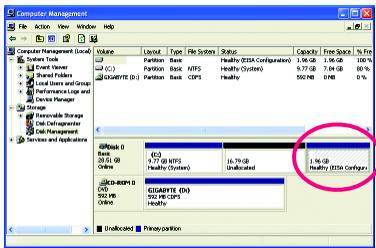
text_image
Computer Management File Action View Window Help Volume Layout Type File System Status Capacity Free Space % Free C:\Program Files\System (C) Partition: Basic Healthy (BSX Configurations) 1.96 GB 1.96 GB 100% GCERTF(D) Partition: Basic CPFS Healthy 552 MB 58 MB 0% SPSSD (D) (D) 14.79 GB SPSSD (D) (F) Unallocated 1.96 GB SPSSD (D) (F) Unallocated Healthy Healthy (BSX Configurations) Unallocated Binary positionFigure 12
Xpress Recovery2 will automatically create a new partition to store the backup image file.
D. Using the Restore Function in Xpress Recovery2
Select RESTORE to restore the backup to your hard drive in case the system breaks down. The RESTORE option will not be present if no backup is created before (Figure 13, 14).

text_image
GIGABYTE™ TECHNOLOGY Xpress2 RECOVERY Ver:1.01.060718 RESTORE BACKUP REMOVE REBOOT © Copyright XWEL GIGABYTE Technology Co., Ltd.Figure 13
text_image
GIGABYTE® TECHNOLOGY RESTORE NOW... Time Edispinal User: Specific/Red, Data Capital: 44MB/$27MBFigure 14
E. Removing the Backup
- If you wish to remove the backup file, select REMOVE (Figure 15).
- After the backup file is removed, no backup image file will be present in Disk Management and hard drive space will be freed up (Figure 16).

text_image
GIGABYTE™ TECHNOLOGY Xpress2 RECOVERY Ver.1.01.060718 RESTORE BACKUP REMOYI REBOOT © Copyright 2008, GIGABYTE Technology Co., Ltd.Figure 15
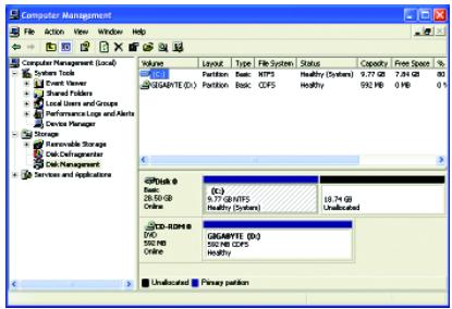
text_image
Computer Management File Action View Window Help Computer Management (Local) System Tools Event Viewer Shared Folders Local Users and Groups Performance Logs and Alerts Device Manager Storage Reversible Storage Disk Refr agoistrator Disk Management Services and applications Volume Layout Type File System Status Capacity Free Space % GIGAPYTE (D:) Partition: Basic: NTFS Healthy (Systems) 3.77 GB 7.84 GB 80 GIGAPYTE (D:) Partition: Basic: CFDS Healthy 992 KB 0 KB 0 % Disk Basic 16 KB/GB Online GIGAPYTE (D:) 542 KB CFDS Healthy Unallocated Primary partitionFigure 16
F. Exiting Xpress Recovery2
Select REBOOT to exit Xpress Recovery2.

text_image
GIGABYTE™ TECHNOLOGY Xpress2 RECOVERY Ver.1.01.060718 RESTORE BACKUP REMOVE RICHOUT © Copyright 2008, GIGABYTE Technology Co., Ltd.Figure 17
4-2 BIOS Update Utilities
GIGABYTE motherboards provide two unique BIOS update tools, Q-Flash™ and @BIOS™. GIGABYTE Q-Flash and @BIOS are easy-to-use and allow you to update the BIOS without the need to enter MS-DOS mode. Additionally, this motherboard features the Dual BIOS™ design, which enhances protection for the safety and stability of your computer by adding one more physical BIOS chip.

What is Dual BIOS™?
Motherboards that support Dual BIOS have two BIOS onboard, a main BIOS and a backup BIOS. Normally, the system works on the main BIOS.
However, if the main BIOS is corrupted or damaged, the backup BIOS will take over on the next system boot and copy the BIOS file to the main BIOS to ensure normal system operation. For the sake of system safety, users cannot update the backup BIOS manually.

What is Q-Flash™?
With Q-Flash you can update the system BIOS without having to enter operating systems like MS-DOS or Window first. Embedded in the BIOS, the
Q-Flash tool frees you from the hassles of going through complicated BIOS flashing process.

What is @BIOS™?
@BIOS allows you to update the system BIOS while in the Windows environment. @BIOS will download the latest BIOS file from the nearest
@BIOS server site and update the BIOS.
4-2-1 Updating the BIOS with the Q-Flash Utility
A. Before You Begin:
- From GIGABYTE's website, download the latest compressed BIOS update file that matches your motherboard model.
- Extract the file and save the new BIOS file (e.g. MA79XDS5.F1) to your floppy disk, USB flash drive, or hard drive. Note: The USB flash drive or hard drive must use FAT32/16/12 file system.
- Restart the system. During the POST, press the
key to enter Q-Flash. Note: You can access Q-Flash by either pressing the key during the POST or pressing the key in BIOS Setup. However, if the BIOS update file is saved to a hard drive in RAID/AHCI mode or a hard drive attached to an independent IDE/SATA controller, use the key during the POST to access Q-Flash.
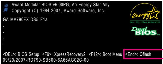
text_image
Award Modular BIOS v6.00PG, An Energy Star Ally Copyright (C) 1984-2007, Award Software, Inc. GA-MA790FX-DS5 F1a : : : : :
Because BIOS flashing is potentially risky, please do it with caution. Inadequate BIOS flashing may result in system malfunction.
B. Updating the BIOS
When updating the BIOS, choose the location where the BIOS file is saved. The follow procedure assumes that you save the BIOS file to a floppy disk.
Step 1:
- Insert the floppy disk containing the BIOS file into the floppy disk drive. In the main menu of Q-Flash, use the up or down arrow key to select Update BIOS from Drive and press
.

- The Save Main BIOS to Drive option allows you to save the current BIOS file.
• Q-Flash only supports USB flash drive or hard drives using FAT32/16/12 file system. -
If the BIOS update file is saved to a hard drive in RAID/AHCI mode or a hard drive attached to an independent IDE/SATA controller, use the
key during the POST to access Q-Flash. -
Select Floppy A and press
.
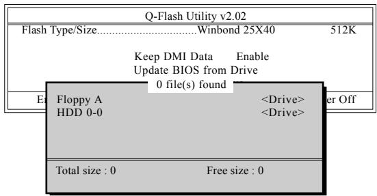
text_image
Q-Flash Utility v2.02 Flash Type/Size......Winbond 25X40 512K Keep DMI Data Enable Update BIOS from Drive 0 file(s) found Floppy A- Select the BIOS update file and press
.

Make sure the BIOS update file matches your motherboard model.
Step 2:
The process of the system reading the BIOS file from the floppy disk is displayed on the screen. When the message "Are you sure to update BIOS?" appears, press

- Do not turn off or restart the system when the system is reading/updating the BIOS.
- Do not remove the floppy disk, USB flash drive, or hard drive when the system is updating the BIOS.
Step 3:
When the update process is complete, press any key to return to the main menu.
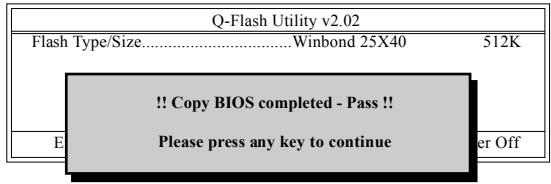
text_image
Q-Flash Utility v2.02 Flash Type/Size......Winbond 25X40 512K !! Copy BIOS completed - Pass !! Please press any key to continue Enter OffStep 4:
Press
Step 5:
During the POST, press
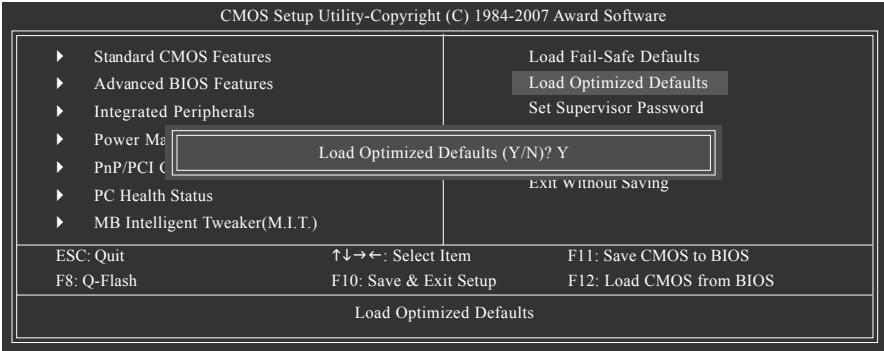
flowchart
graph TD
    A["Standard CMOS Features"] --> B["Advanced BIOS Features"]
    B --> C["Integrated Peripherals"]
    D["Power Ma"] --> E["Load Optimized Defaults (Y/N)? Y"]
    F["PnP/PCI C"] --> E
    G["PC Health Status"] --> H["Exit Without Saving"]
    I["MB Intelligent Tweaker(M.I.T.)"] --> H
    J["ESC: Quit"] --> K["↑↓→←: Select Item"]
    L["F8: Q-Flash"] --> M["F10: Save & Exit Setup"]
    N["F11: Save CMOS to BIOS"] --> O["F12: Load CMOS from BIOS"]
    P["Load Optimized Defaults"] --> Q["Load Fail-Safe Defaults"]
    R["Load Optimized Defaults"] --> S["Set Supervisor Password"]
Press
Step 6:
Select Save & Exit Setup and then press
4-2-2 Updating the BIOS with the @BIOS Utility
A. Before You Begin:
- In Windows, close all applications and TSR (Terminate and Stay Resident) programs. This helps prevent unexpected failures when performing a BIOS update.
- During the BIOS update process, ensure the Internet connection is stable and do NOT interrupt the Internet connection (for example, avoid a power loss or switching off the Internet). Failure to do so may result in a corrupted BIOS or a system that is unable to start.
- Do not use the C.O.M. (Corporate Online Management) function when using @BIOS.
- GIGABYTE product warranty does not cover any BIOS damage or system failure resulting from an inadequate BIOS flashing.
B. Installing and Using @BIOS:
Use the motherboard driver disk included with the motherboard to install @BIOS.
• Installing the @BIOS utility.

text_image
GIGABYTE® AMD 7-Series Discrete Utilities CD Software Applications Please click the following applications to install. All-First Utility GIGABYTE & COM (Corporate Online Manager) BND Ave-Bio based system management tool that allows client system hardware information such as CPU and memory and graphics card and push more to be processed or connected to a tool EasyScope 5 Pro BND An Active and Network-based system enhancement ability allowing quick access to safety or performance features DSM Viewer BND DSM Viewer process management tool for accessing network-based hardware information. Face Wizard BND Face Wizard provides skills for customizing BIOS backup screen. BIOS BND BIOS product ability to setting BIOS through BIOS 100%- BND Cust power ability to adjust BIOS performance. Select @BIOS and click Install.- Accessing the @BIOS utility.
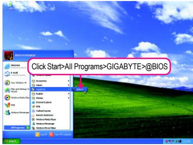
text_image
Click Start>All Programs>GIGABYTE>@BIOSC. Options and Instructions:
1. Save the Current BIOS File
In the main dialog box of @BIOS, Save Current BIOS allows you to save the current BIOS file.
2. Update the BIOS Using the Internet Update Function
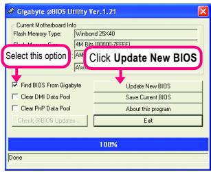
text_image
Gigabyte eBIOS Utility Ver.1.21 Current Motherboard Info Flash Memory Type: Virbond 25X40 4M Bps (000007EFEF) AM AW Select this option Click Update New BIOS Find BIDS From Gigabyte Clear DMI Data Pool Clear PrP Data Pool Check @BIOS Updates Update New BIOS Save Current BIOS About this program Exit 100% Done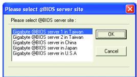
text_image
Please select @BIOS server site Please select @BIOS server site: Gigabyte@BIOS server 1 in Taiwan Gigabyte@BIOS server 2 in Taiwan Gigabyte@BIOS server in China Gigabyte@BIOS server in Japan Gigabyte@BIOS server in U.S.A OK CancelStep 2:
Select the @BIOS server site closest to your location and click OK.
Step 1:
Select the Find BIOS From Gigabyte check box and click Update New BIOS.
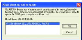
text_image
Please select one file to update WARNING: Before you select the model name from the list below, please select the exact model name on your menarche. If you select the wrong model name to update the BIOS, your computers would not boot. Model Name : GA-KONXP-SL1 aVIDIA aPowered SL1, AWARD BIOS, Ver F11 OK CancelStep 3:
First make sure the model name on the screen is correct, then click OK. Upon completion, restart your system.

- If more than one model is present when doing Step 3 above, reconfirm your motherboard model. Updating the BIOS with an incorrect BIOS file could result in an unbootable system.
- If the BIOS update file for your motherboard is not present on the @BIOS server site, please manually download the BIOS update file from GIGABYTE's website and follow the instructions in "Update the BIOS without Using the Internet Update Function" below.
Step 4:
As the system reboots, press
3. Update the BIOS without Using the Internet Update Function
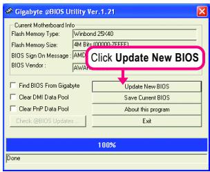
text_image
Gigabyte @BIOS Utility Ver.1.21 Current Motherboard Info Flash Memory Type: W/nbond 25x40 Flash Memory Size: 4M Bits (00000.76EFE) BIOS Sign On Message: AMD BIOS Vendor: AWAY Find BIOS From Gigabyte Clear DMI Data Pool Clear FPrP Data Pool Check @BIOS Updates Click Update New BIOS Update New BIOS Save Current BIOS About this program Exit 100% DoneStep 1:
Click Update New BIOS.
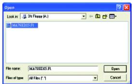
text_image
Open Look in: 3% Flange (A:) MAXXXXXS.FI File name: MAXXXXXS.FI Files of type: All Files (*.*)Step 2:
In the Open dialog box, select All Files (*.*) in the Files of type list. Select the location where you save the BIOS update file (e.g. MA79XDS5.F1) obtained from the Internet or through other source.
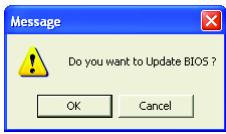
text_image
Message Do you want to Update BIOS ? OK CancelStep 3:
Press OK to begin the BIOS update process. Upon completion, restart your system.

Make sure the extracted BIOS file matches your motherboard model. Updating the BIOS with an incorrect BIOS file could result in an unbootable system.
Step 4:
As the system boots, press
4-3 EasyTune 5 Pro
EasyTune™ 5 Pro, an easy-to-use and convenient system overclocking and management tool, lets you do overclock and overvoltage in Windows environment, eliminating the need to enter the BIOS Setup program. EasyTune 5 Pro provides the following functions (Note 1): overclocking/overvoltage, C.I.A./M.I.B. (Note 2), smart fan control, and hardware monitoring and warning. (For instructions on using EasyTune5 Pro, read or download the information on/from the Support\Motherboard\Utility page on our website.)
The EasyTune 5 Pro Interface
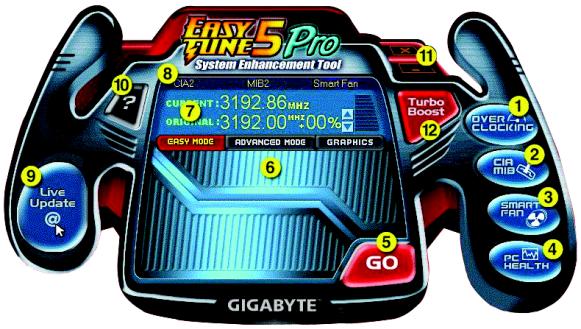
text_image
EASY FIRE 5 Pro System Enhancement Tool GIBA2 MIB2 Smart Fan CURRENT: 3192.86 MHz ORIGINAL: 3192.00 MHz+00% GIBY MODE ADVANCED MODE GRAPHICS Turbo Boost OVER CLOCKING Live Update @ GO GIGABYTEButton Information Table
| Button/Display | Description | |
| 1. | OVERCLOCKING | Enters the OVERCLOCKING setting page |
| 2. | C.I.A./M.I.B. | Enters the C.I.A. and M.I.B. setting page |
| 3. | SMART FAN | Enters the SMART FAN setting page |
| 4. | PC HEALTH | Enters the PC HEALTH setting page |
| 5. | GO | Confirmation/execution button |
| 6. | EASY MODE/ADVANCED MODE/GRAPHICS | Toggles among Easy Mode, Advanced Mode, and Graphics Mode |
| 7. | Display Area | Displays the CPU frequency |
| 8. | Function LEDs | Shows the supported function(s) |
| 9. | Live Update | Go to GIGABYTE website to update EasyTune 5 Pro |
| 10. | Help | Opens EasyTune 5 Pro help file |
| 11. | Exit/Minimize | Quits or minimizes the EasyTune 5 Pro interface |
| 12. | Turbo Boost | Performance Enhancement |

Incorrectly doing overclock/overvoltage may result in damage to CPU, chipset, or memory and reduce the useful life of these components. Before you do the overclock/overvoltage, make sure that you fully know how to use each function of EasyTune 5 Pro, or system instability or other unexpected results may occur.
(Note 1) Available functions in EasyTune 5 Pro may differ by motherboard model.
(Note 2) C.I.A. and M.I.B. may provide optimizations for CPU and memory, enhancing the performance of these components.
4-4 Windows Vista ReadyBoost
Windows ReadyBoost allows you to use flash memory on a Windows Vista certified USB flash drive to boost your computer's performance. You may enable ReadyBoost and allocate part of your USB flash drive's memory to speed up your computer.
Follow the steps below to enable the ReadyBoost function:
text_image
Computer Name: Type: Auto Web File Edit View (S) Local Site (C) Local Site (D) Device with Remote Change (I) Pages: 3x3x3x3x3x3x3x3x3x3x3x3x3x3x3x3x3x3x3x3x3x3x3x3x3x3x3x3x3x3x3x3x3x3x3x3x3x3x3x3x3x3x3x3x3x3x3x3x3x3x3 Page 12-01-01-01-01-01-01-01-01-01-01-01-01-01-01-01-01-01-01-01-01-01-01-01-01-01-01-01-01-01-01-01-01-01 Personal Data File System: A452 Open Save Help Open to Open Status Export... Help Help to Print Help to Print Help to Print Help to Print Help to Print Help to Print Help to Print Help to Print Help to Print Help to Print Help to Print Help to Print Help to Print Help to Print Help to Print Help to Print Help to Print Help to Print Help to Print Help to Print Help to Print Help to Print Help to Print Help to Print Help to Print Help toPrintStep 1:
Go to Computer. Right-click on the USB flash drive icon and choose Properties.
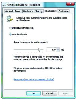
text_image
Removable Disk (D:) Properties General Tools Hardware Sharing Ready/Boost Customize Speed up your system by utilizing the available space on this device. Do not use this device. Use this device. Space to reserve for system speed: 870 MB While the device is being used for system speed the reserved space will not be available for file storage. Windows recommends reserving 870 MB for optimal performance. Please read our privacy statement (online) OK Cancel ApplyStep 2:
In the ReadyBoost tab, select Use this device. Under Space to reserve for system speed, set the amount of memory space to use for ReadyBoost using the slider or spin box. Click Apply and then OK to turn on ReadyBoost.

- The USB flash drive must have at least 256 MB of space.
- The recommended amount of memory to use for ReadyBoost acceleration is one to three times the amount of RAM installed in your computer.
Chapter 5 Appendix
5-1 Configuring SATA Hard Drive(s)
To configure SATA hard drive(s), follow the steps below:
A. Install SATA hard drive(s) in your computer.
B. Configure SATA controller mode in BIOS Setup.
C. Configure a RAID array in RAID BIOS. (Note 1)
D. Make a floppy disk containing the SATA RAID/AHCI driver. (Note 2)
E. Install the SATA RAID/AHCI driver and operating system. (Note 2)
Before you begin
Please prepare:
- At least two SATA hard drives (to ensure optimal performance, it is recommended that you use two hard drives with identical model and capacity). If you do not want to create RAID, you may prepare only one hard drive.
- An empty formatted floppy disk.
- Windows Vista/XP/2000 setup disk.
- Motherboard driver disk.
5-1-1 Configuring AMD SB600 SATA Controllers
A. Installing SATA hard drive(s) in your computer
Attach one end of the SATA signal cable to the rear of the SATA hard drive and the other end to available SATA port on the motherboard. If there is more than one SATA controller on your motherboard, refer to "Chapter 1," "Hardware Installation," to identify the SATA controller for the SATA port. (For example, on this motherboard, the SATAII0, SATAII1, SATAII2 and SATAII3 ports are supported by AMD SB600 Southbridge.) Then connect the power connector from your power supply to the hard drive.
(Note 1) Skip this step if you do not want to create RAID array on the SATA controller.
(Note 2) Required when the SATA controller is set to AHCI or RAID mode.
B. Configuring SATA controller mode in BIOS Setup
Make sure to configure the SATA controller mode correctly in system BIOS Setup.
Step 1:
Turn on your computer and press
| ► IDF Configuration [Press Enter] | Item Help | |
| OnChip SATA Controller [Enabled] | Menu Level▶ | |
| OnChip SATA Type [RAID] | ||
| ► OnBoard PCIe Device [Press Enter] | ||
| Onboard Audio Function [Auto] | ||
| Onboard 1394 Function [Enabled] | ||
| OnChip USB Controller [Enabled] | ||
| USB EHCI Controller [Enabled] | ||
| USB Keyboard Support [Disabled] | ||
| USB Mouse Support [Disabled] | ||
| Legacy USB storage detect [Enabled] | ||
| Onboard Serial Port 1 [3F8/IRQ4] | ||
| Onboard Parallel Port [378/IRQ7] | ||
| Parallel Port Mode [SPP] | ||
| x ECP Mode Use DMA 3 | ||
| ↑↓→←: Move Enter: Select +/-PU/PD: Value F10: Save ESC: Exit F1: General Help F5: Previous Values F6: Fail-Safe Defaults F7: Optimized Defaults | ||
Figure 1
Step 2:
Save changes and exit BIOS Setup.

The BIOS Setup menus described in this section may differ from the exact settings for your motherboard. The actual BIOS Setup menu options you will see shall depend on the motherboard you have and the BIOS version.
C. Configuring RAID set in RAID BIOS
Enter the RAID BIOS setup utility to configure a RAID array. Skip this step if you do not want to create RAID.
Step 1:
After the POST memory test begins and before the operating system boot begins, look for a message which says "Press
RAID BIOS Version 2.5.1540_36
(c) 2006 ATI Technology, Inc. All rights reserved.
No Array is defined..
Press <Ctrl-F> to enter FastBuild (tm) Utility...
Figure 2
Step 2:
Main Menu
This is the first option screen when you enter the ATI BIOS RAID Setup utility. (Figure 3).
To view the disk drives assigned to arrays, press <1> to enter the View Drive Assignments window.
To create an array, press <2> to enter the Define LD window.
To delete an array, press <3> to enter the Delete LD window.
To view controller settings, press <4> to enter the Controller Configuration window.
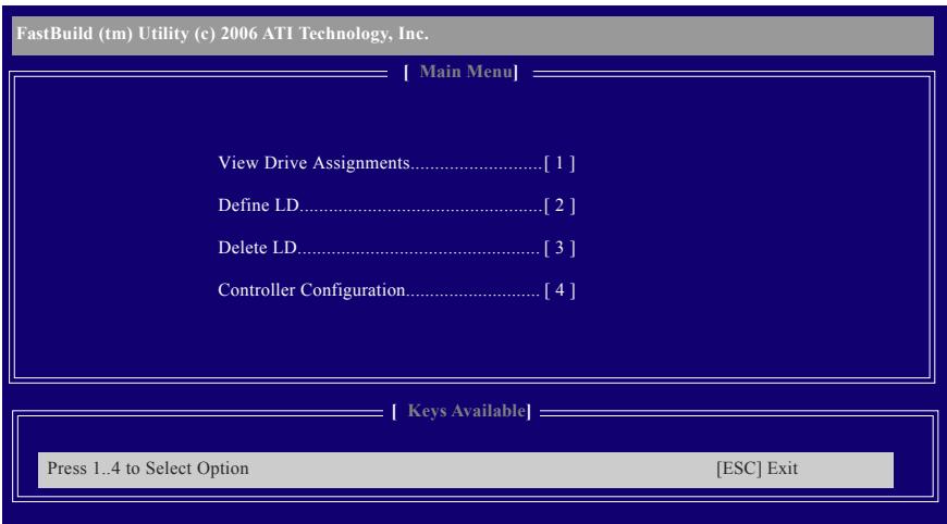
text_image
FastBuild (tm) Utility (c) 2006 ATI Technology, Inc. [ Main Menu ] View Drive Assignments......[ 1 ] Define LD......[ 2 ] Delete LD......[ 3 ] Controller Configuration......[ 4 ] [ Keys Available ] Press 1..4 to Select Option [ESC] ExitFigure 3
Create Arrays Manually
To create a new array, press <2> to enter the Define LD window (Figure 4). The Define LD selection from the Main Menu allows users to begin the process of manually defining the drive elements and RAID levels for one or multiple disk arrays attached to the AMD SB600 controller.
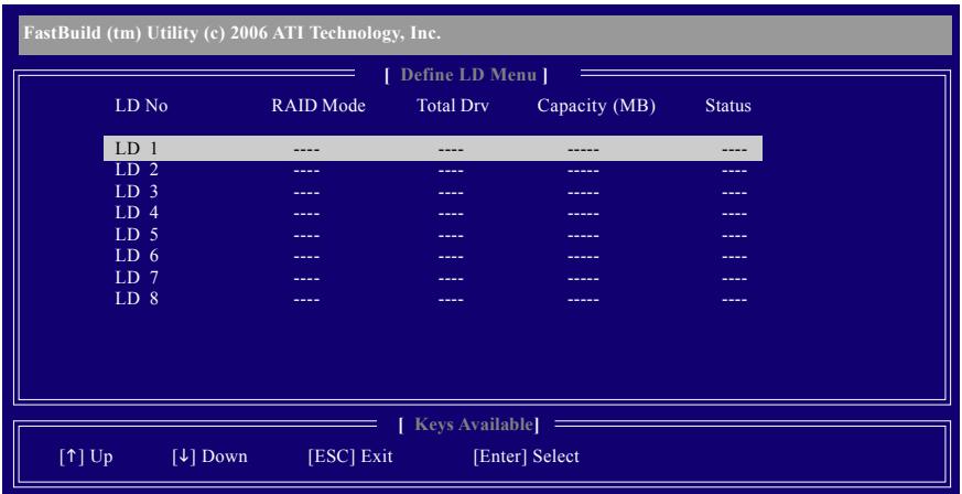
text_image
FastBuild (tm) Utility (c) 2006 ATI Technology, Inc. [ Define LD Menu ] LD No RAID Mode Total Drv Capacity (MB) Status LD 1 ---- ---- ---- ---- LD 2 ---- ---- ---- ---- LD 3 ---- ---- ---- ---- LD 4 ---- ---- ---- ---- LD 5 ---- ---- ---- ---- LD 6 ---- ---- ---- ---- LD 7 ---- ---- ---- ---- LD 8 ---- ---- ---- ---- [ Keys Available ] [↑] Up [↓] Down [ESC] Exit [Enter] SelectFigure 4
In Figure 4, use arrow keys [] to move to a logical disk set and press
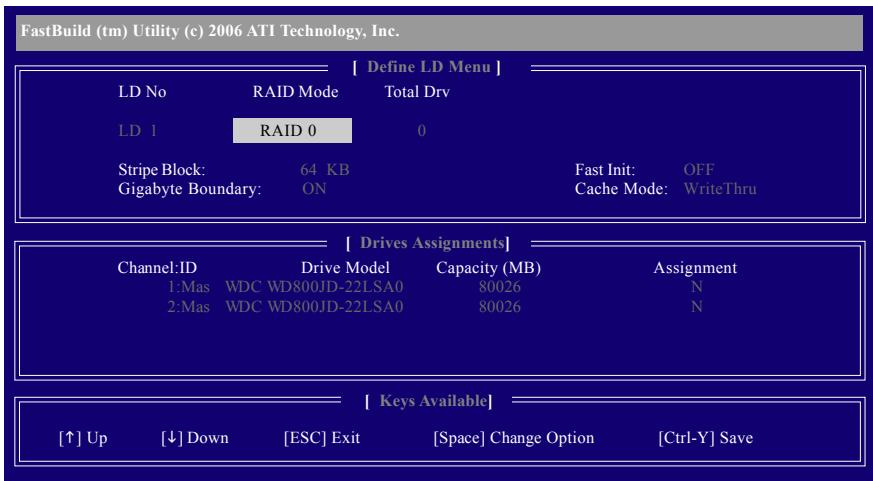
text_image
FastBuild (tm) Utility (c) 2006 ATI Technology, Inc. [ Define LD Menu ] LD No RAID Mode Total Drv LD 1 RAID 0 0 Stripe Block: 64 KB Fast Init: OFF Gigabyte Boundary: ON Cache Mode: WriteThru [ Drives Assignments ] Channel:ID Drive Model Capacity (MB) Assignment 1:Mas WDC WD800JD-22LSA0 80026 N 2:Mas WDC WD800JD-22L.SA0 80026 N [ Keys Available ] [↑] Up [↓] Down [ESC] Exit [Space] Change Option [Ctrl-Y] SaveFigure 5
In the following procedure, we'll create RAID 0 as an example.
- Under the RAID Mode section, press the Spacebar to select RAID 0.
- Set the Stripe Block size. 64 KB is the default.
- Under the Drives Assignments section, press the up or down arrow key to highlight a drive.
- Press the Spacebar or
to change the Assignment option to Y. This action adds the drive to the disk array. The Total Drv section will show the number of disks assigned. - Press
+ keys to save the information. The window below will appear.
Press Ctrl-Y to Modify Array Capacity or press any other key to use maximum capacity...
Figure 6
- Press
+ to set the capacity of the RAID array or press other keys to set the array to its maximum capacity. - After the creation is complete, the screen will return to Define LD Menu where you will see the newly-created array.
- Press
to return to Main Menu and press again if you want to exit the RAID BIOS utility.
View Drive Assignments
The View Drive Assignments option in the Main Menu displays whether drives attached to the ATI SB600 controller are assigned to a disk array or are unassigned. Under the Assignment column, drives are labeled with their assigned disk array or shown as Free if unassigned.
FastBuild (tm) Utility (c) 2006 ATI Technology, Inc.
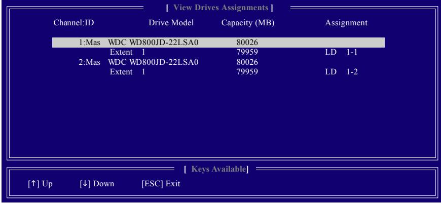
text_image
[ View Drives Assignments ] Channel:ID Drive Model Capacity (MB) Assignment 1:Mas WDC WD800JD-22LSA0 80026 Extent 1 79959 LD 1-1 2:Mas WDC WD800JD-22LSA0 80026 Extent 1 79959 LD 1-2 [ ↑ ] Up [ ↓ ] Down [ ESC ] Exit [ Keys Available ]Figure 7
Delete an Array
The Delete Array menu option allows for deletion of disk array assignments.

Deleting an existing disk array could result in loss of data. Record all array information including the array type, the disk members, and stripe block size in case you wish to undo a deletion.
- To delete an array, press <3> in the Main Menu to enter the Delete LD Menu. Then highlight the array you wish to delete and press the
key or the + keys. - The View LD Definition Menu will appear (as shown in Figure 8) showing which drives are assigned to this array. Press
+ if you are sure to delete the array or other keys to abort. - When the array is deleted, the screen will return to Delete LD Menu. Press
to return to Main Menu.
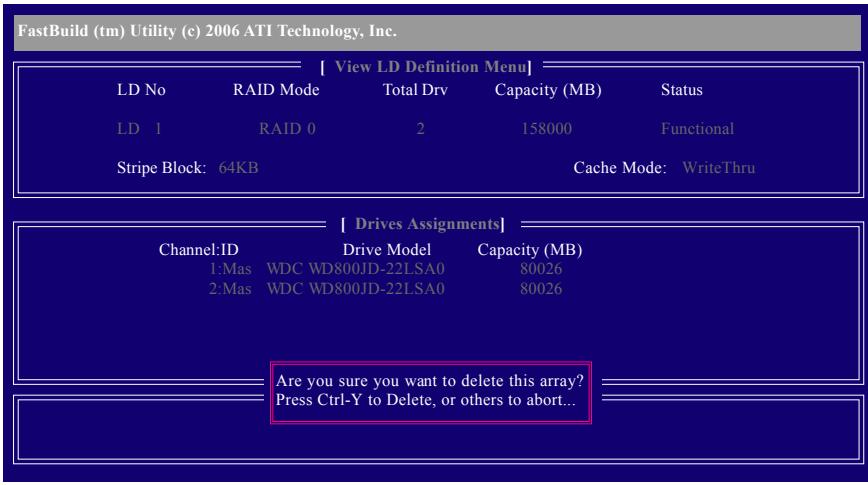
text_image
FastBuild (tm) Utility (c) 2006 ATI Technology, Inc. [ View LD Definition Menu ] LD No RAID Mode Total Drv Capacity (MB) Status LD 1 RAID 0 2 158000 Functional Stripe Block: 64KB Cache Mode: WriteThru [ Drives Assignments ] Channel:ID Drive Model Capacity (MB) 1:Mas WDC WD800JD-22LSA0 80026 2:Mas WDC WD800JD-22LSA0 80026 Are you sure you want to delete this array? Press Ctrl-Y to Delete, or others to abort...Figure 8
5-1-2 Configuring GIGABYTE SATA2 SATA Controller
A. Installing SATA hard drive(s) in your computer
Attach one end of the SATA signal cable to the rear of the SATA hard drive and the other end to available SATA port on the motherboard. If there is more than one SATA controller on your motherboard, refer to "Chapter 1," Hardware Installation," to identify the SATA controller for the SATA port. (For example, on this motherboard, the GSATAII_1, GSATAII_2 and eSATA ports are supported by GIGABYTE SATA2.) Then connect the power connector from your power supply to the hard drive.
B. Configuring SATA controller mode and device boot order in BIOS Setup
Make sure to configure the SATA controller mode correctly in system BIOS Setup and set the device boot order.
Step 1:
Turn on your computer and press
| ►IDE Configuration [Press Enter] OnChip SATA Controller [Enabled] OnChip SATA Type [Native IDE] | Item Help | |
| Menu Level▶ | ||
| ►OnBoard PCIE Device [Press Enter] | ||
| Onboard Audio Function [Auto] | ||
| Onboard 1394 Function [Enabled] | ||
| OnChip USB Controller [Enabled] | ||
| USB EHCI Controller [Enabled] | ||
| USB Keyboard Support [Disabled] | ||
| USB Mouse Support [Disabled] | ||
| Legacy USB storage detect [Enabled] | ||
| Onboard Serial Port 1 [3F8/IRQ4] | ||
| Onboard Parallel Port [378/IRQ7] | ||
| Parallel Port Mode [SPP] | ||
| x ECP Mode Use DMA 3 | ||
| ↑↓→←: Move Enter: Select +/-/PU/PD: Value F10: Save ESC: Exit F1: General Help F5: Previous Values F6: Fail-Safe Defaults F7: Optimized Defaults | ||
Figure 1
For example, if you wish to create RAID with hard drives on the GSATAII_1 and GSATAII_2 connectors, ensure that Onboard GSATA-II Ctrl is enabled. Set Onboard GSATA-II Ctrl Mode to RAID (Figure 2). If you do not want to create RAID, set this item to IDE or AHCI, depending on your need.
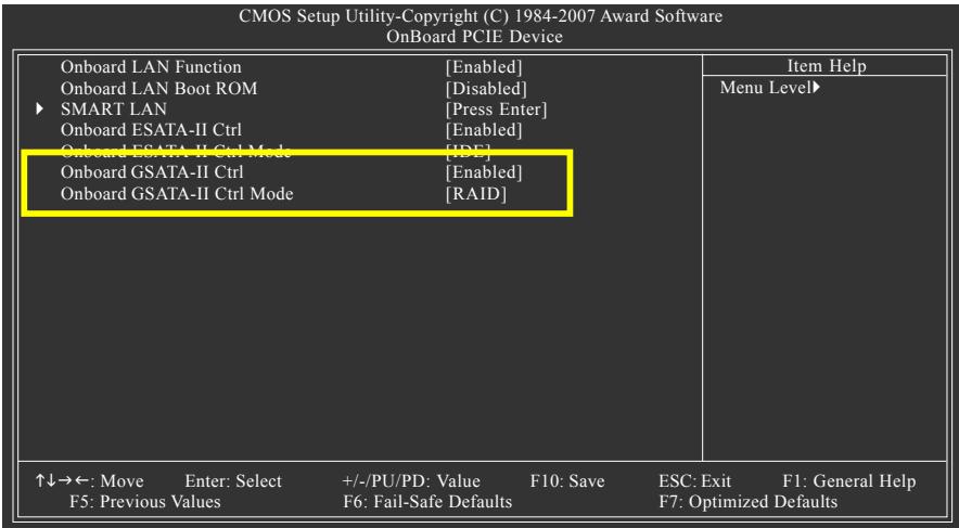
text_image
CMOS Setup Utility-Copyright (C) 1984-2007 Award Software OnBoard PCIE Device Onboard LAN Function [Enabled] Onboard LAN Boot ROM [Disabled] ► SMART LAN [Press Enter] Onboard ESATA-II Ctrl [Enabled] Onboard ESATA-II Ctrl Mode [IDE] Onboard GSATA-II Ctrl [Enabled] Onboard GSATA-II Ctrl Mode [RAID] ↑↓→←: Move Enter: Select +/-/PU/PD: Value F10: Save ESC: Exit F1: General Help F5: Previous Values F6: Fail-Safe Defaults F7: Optimized DefaultsFigure 2
For example, if you wish to create RAID with hard drives on the eSATA 3Gb/s ports, ensure that Onboard ESATA-II Ctrl is enabled. Set Onboard ESATA-II Ctrl Mode to RAID (Figure 2). If you do not want to create RAID, set this item to IDE or AHCI, depending on your need.
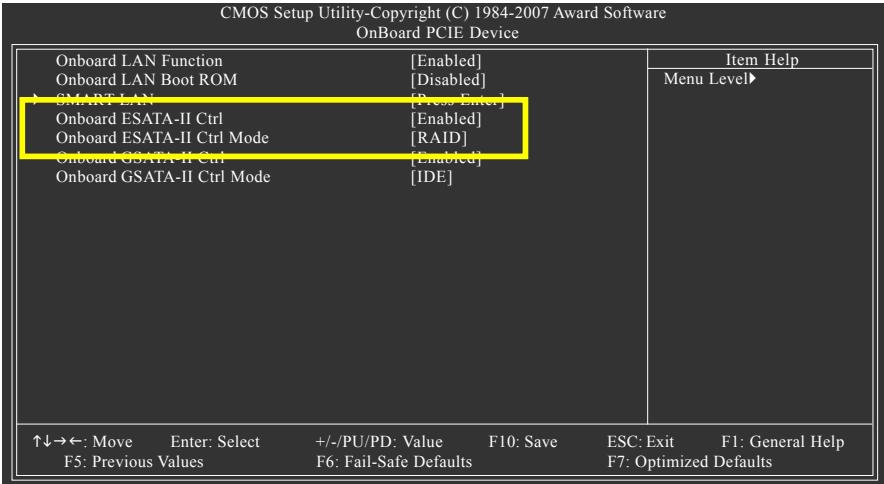
text_image
CMOS Setup Utility-Copyright (C) 1984-2007 Award Software OnBoard PCIE Device Onboard LAN Function [Enabled] Onboard LAN Boot ROM [Disabled] SMART LAN [Press Enter] Onboard ESATA-II Ctrl [Enabled] Onboard ESATA-II Ctrl Mode [RAID] Onboard GSATA-II Ctrl [Enabled] Onboard GSATA-II Ctrl Mode [IDE] ↑↓→←: Move Enter: Select +/-/PU/PD: Value F10: Save ESC: Exit F1: General Help F5: Previous Values F6: Fail-Safe Defaults F7: Optimized Defaults Item Help Menu Level▶Figure 2
Step 2:
Save changes and exit BIOS Setup.

The BIOS Setup menus described in this section may differ from the exact settings for your motherboard. The actual BIOS Setup menu options you will see shall depend on the motherboard you have and the BIOS version.
C. Configuring a RAID array in RAID BIOS
Enter the RAID BIOS setup utility to configure a RAID array. Skip this step and proceed to the installation of Windows operating system for a non-RAID configuration.
After the POST memory test begins and before the operating system boot begins, look for a message which says "Press
| GIGABYTE Technology Corp. PCIE-to-SATAII/IDE RAID Controller BIOSv1.06.59 Copyright (C) 2006-2007 GIGABYTE Technology. http://www.gigabyte.com.tw | ||
| HDD0 : ST3120026AS | 120 GB Non-RAID | |
| HDD1 : ST3120026AS | 120 GB Non-RAID | |
| ODD0 : DVDROM GO-D1600B | ||
| Press <Ctrl-G> to enter RAID Setup Utility ... | ||
Figure 3
In the main screen of the GIGABYTE SATA2 RAID BIOS utility (Figure 4), use the up or down arrow key to highlight through choices in the Main Menu block. Highlight the item that you wish to execute and press
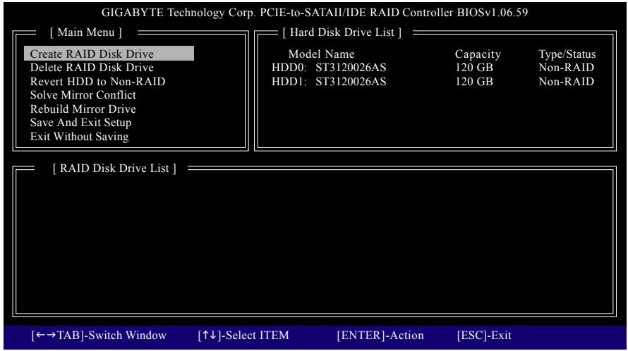
text_image
GIGABYTE Technology Corp. PCIE-to-SATAII/IDE RAID Controller BIOSv1.06.59 [ Main Menu ] Create RAID Disk Drive Delete RAID Disk Drive Revert HDD to Non-RAID Solve Mirror Conflict Rebuild Mirror Drive Save And Exit Setup Exit Without Saving [ Hard Disk Drive List ] Model Name Capacity Type/Status HDD0: ST3120026AS 120 GB Non-RAID HDD1: ST3120026AS 120 GB Non-RAID [ RAID Disk Drive List ] [←→TAB]-Switch Window [↑↓]-Select ITEM [ENTER]-Action [ESC]-ExitFigure 4
Note: In the main screen, you can select a hard drive in the Hard Disk Drive List block and press
Create a RAID Array:
In the main screen, press
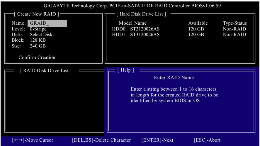
text_image
GIGABYTE Technology Corp. PCIE-to-SATAII/IDE RAID Controller BIOSv1.06.59 [ Create New RAID ] Name: GRAID Level: 0-Stripe Disks: Select Disk Block: 128 KB Size: 240 GB Confirm Creation [ Hard Disk Drive List ] Model Name Available Type/Status HDD0: ST3120026AS 120 GB Non-RAID HDD1: ST3120026AS 120 GB Non-RAID [ RAID Disk Drive List ] [ Help ] Enter RAID Name Enter a string between 1 to 16 characters in length for the created RAID drive to be identified by system BIOS or OS. [←→]-Move Cursor [DEL,BS]-Delete Character [ENTER]-Next [ESC]-AbortFigure 5
The Create New RAID block displays all the items that need to be set for creating an array (Figure 6).
Steps:
- Enter Array Name: Under the Name item, enter an array name with 1\~16 letters (letters cannot be special characters) and press
. - Select RAID Mode: Under the Level item, use up or down arrow key to select RAID 0 (Stripe), RAID 1 (Mirror), or JBOD (Figure 6). Then press
to move onto the next step.
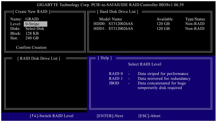
text_image
GIGABYTE Technology Corp. PCIE-to-SATAI/IDE RAID Controller BIOSv1.06.59 [ Create New RAID ] Name: GRAID Level: 0-Stripe Disks: Select Disk Block: 128 KB Size: 240 GB Confirm Creation [ Hard Disk Drive List ] Model Name Available Type/Status HDD0: ST3120026AS 120 GB Non-RAID HDD1: ST3120026AS 120 GB Non-RAID [ RAID Disk Drive List ] [ Help ] Select RAID Level RAID 0 - Data striped for performance RAID 1 - Data mirrored for redundancy JBOD - Data concatenated for huge temporarily disk required [↑↓]-Switch RAID Level [ENTER]-Next [ESC]-AbortFigure 6
- Assign Array Disks: After a RAID mode is selected, RAID BIOS automatically assigns the two hard drives installed as the RAID drives.
- Set Block Size (RAID 0 only): Under the Block item, use the up or down arrow key to select the stripe block size (Figure 7), ranging from 4 KB to 128 KB. Press
.
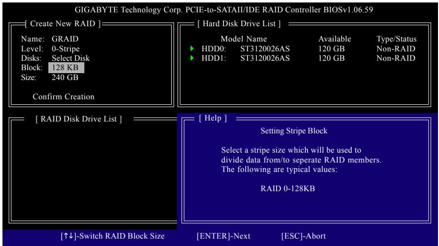
text_image
GIGABYTE Technology Corp. PCIE-to-SATAI/IDE RAID Controller BIOSv1.06.59 [ Create New RAID ] Name: GRAID Level: 0-Stripe Disks: Select Disk Block: 128 KB Size: 240 GB Confirm Creation [ Hard Disk Drive List ] Model Name Available Type/Status ► HDD0: ST3120026AS 120 GB Non-RAID ► HDD1: ST3120026AS 120 GB Non-RAID [ RAID Disk Drive List ] [ Help ] Setting Stripe Block Select a stripe size which will be used to divide data from/to separate RAID members. The following are typical values: RAID 0-128KB [↑↓]-Switch RAID Block Size [ENTER]-Next [ESC]-AbortFigure 7
- Set Array Size: Under the Size item, enter the size of the array and press
. - Confirm Creation: After all of the items above are configured, the selection bar automatically jumps to the Confirm Creation item. Press
. When prompted to confirm your selection (Figure 8), press to confirm or to abort.
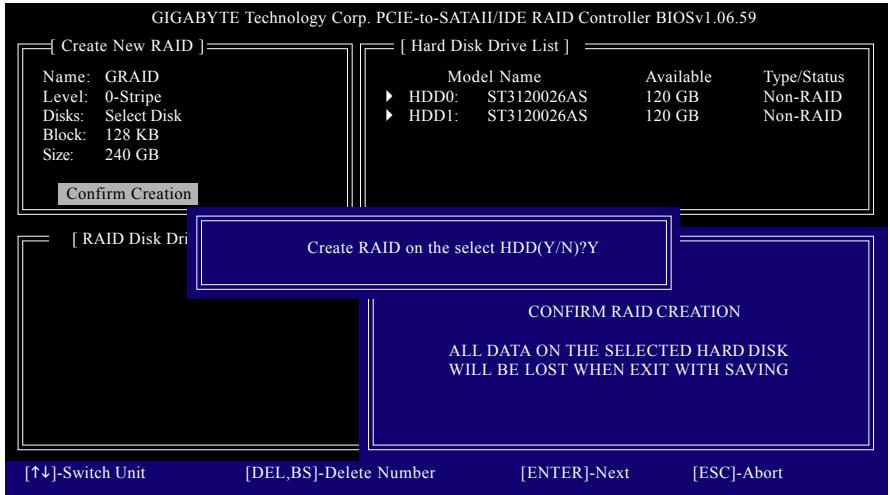
text_image
GIGABYTE Technology Corp. PCIE-to-SATAII/IDE RAID Controller BIOSv1.06.59 [ Create New RAID ] Name: GRAID Level: 0-Stripe Disks: Select Disk Block: 128 KB Size: 240 GB [ Hard Disk Drive List ] Model Name Available Type/Status ► HDD0: ST3120026AS 120 GB Non-RAID ► HDD1: ST3120026AS 120 GB Non-RAID Confirm Creation [ RAID Disk Dri Create RAID on the select HDD(Y/N)?Y CONFIRM RAID CREATION ALL DATA ON THE SELECTED HARD DISK WILL BE LOST WHEN EXIT WITH SAVING [↑↓]-Switch Unit [DEL,BS]-Delete Number [ENTER]-Next [ESC]-AbortFigure 8
When finished, the new RAID array will be displayed in the RAID Disk Drive List block (Figure 9).
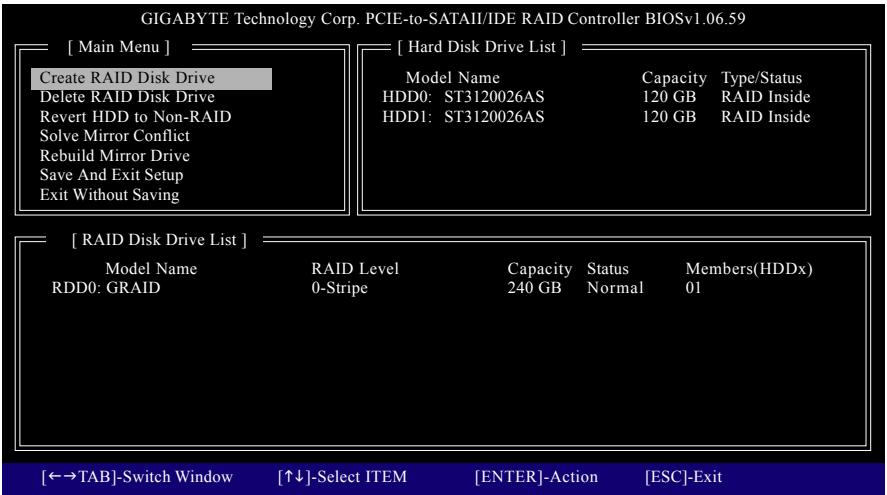
text_image
GIGABYTE Technology Corp. PCIE-to-SATAII/IDE RAID Controller BIOSv1.06.59 [ Main Menu ] Create RAID Disk Drive Delete RAID Disk Drive Revert HDD to Non-RAID Solve Mirror Conflict Rebuild Mirror Drive Save And Exit Setup Exit Without Saving [ Hard Disk Drive List ] Model Name Capacity Type/Status HDD0: ST3120026AS 120 GB RAID Inside HDD1: ST3120026AS 120 GB RAID Inside [ RAID Disk Drive List ] Model Name RAID Level Capacity Status Members(HDDx) RDD0: GRAID 0-Stripe 240 GB Normal 01 [←→TAB]-Switch Window [↑↓]-Select ITEM [ENTER]-Action [ESC]-ExitFigure 9
To check more detailed information about the array, use the
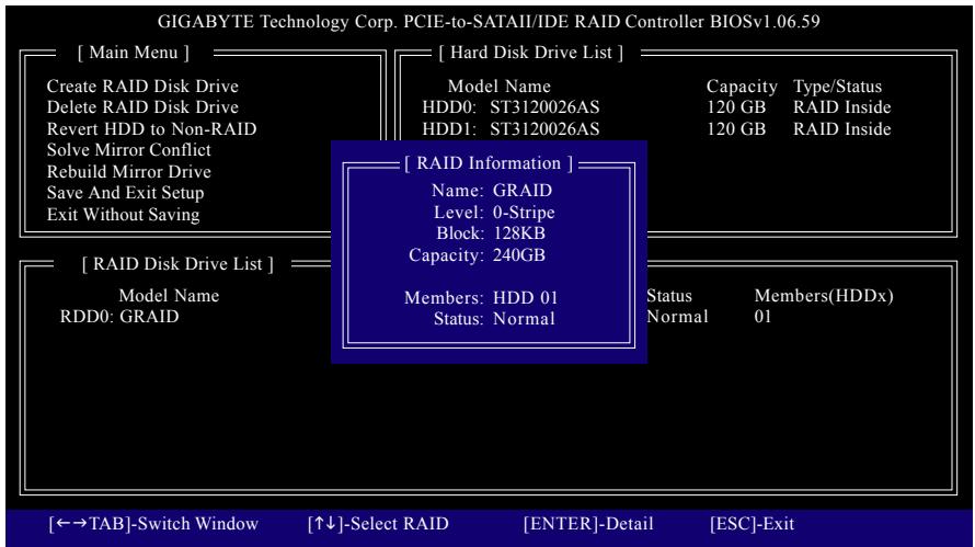
text_image
GIGABYTE Technology Corp. PCIE-to-SATAII/IDE RAID Controller BIOSv1.06.59 [ Main Menu ] Create RAID Disk Drive Delete RAID Disk Drive Revert HDD to Non-RAID Solve Mirror Conflict Rebuild Mirror Drive Save And Exit Setup Exit Without Saving [ Hard Disk Drive List ] Model Name HDD0: ST3120026AS HDD1: ST3120026AS Capacity Type/Status 120 GB RAID Inside 120 GB RAID Inside [ RAID Information ] Name: GRAID Level: 0-Stripe Block: 128KB Capacity: 240GB [ RAID Disk Drive List ] Model Name RDD0: GRAID Members: HDD 01 Status: Normal Status Members(HDDx) Normal 01 [←→TAB]-Switch Window [↑↓]-Select RAID [ENTER]-Detail [ESC]-ExitFigure 10
- Save and Exit Setup: After configuring the RAID array, select the Save And Exit Setup item in the main screen to save your settings before exiting the RAID BIOS utility, then press
(Figure 11).
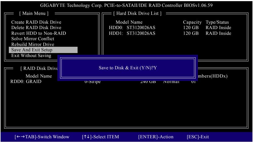
text_image
GIGABYTE Technology Corp. PCIE-to-SATAII/IDE RAID Controller BIOSv1.06.59 [ Main Menu ] Create RAID Disk Drive Delete RAID Disk Drive Revert HDD to Non-RAID Solve Mirror Conflict Rebuild Mirror Drive Save And Exit Setup Exit Without Saving [ Hard Disk Drive List ] Model Name Capacity Type/Status HDD0: ST3120026AS 120 GB RAID Inside HDD1: ST3120026AS 120 GB RAID Inside [ RAID Disk Drive ] Model Name RDD0: GRAID Save to Disk & Exit (Y/N)?Y 0-Stripe 240 GB Normal 01 Numbers(HDDx) [←→TAB]-Switch Window [↑↓]-Select ITEM [ENTER]-Action [ESC]-ExitFigure 11
Now, you may proceed to create the SATA RAID/AHCI driver diskette and the installation of the SATA RAID/AHCI driver and operating system.
Delete the RAID Array:
To delete the array, select Delete RAID Disk Drive in the main menu and press
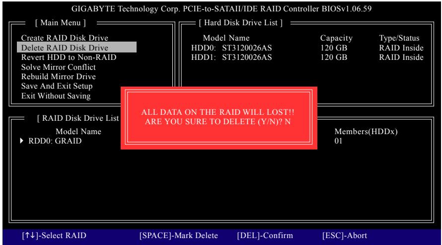
text_image
GIGABYTE Technology Corp. PCIE-to-SATAII/IDE RAID Controller BIOSv1.06.59 [ Main Menu ] Create RAID Disk Drive Delete RAID Disk Drive Revert HDD to Non-RAID Solve Mirror Conflict Rebuild Mirror Drive Save And Exit Setup Exit Without Saving [ Hard Disk Drive List ] Model Name HDD0: ST3120026AS HDD1: ST3120026AS Capacity 120 GB 120 GB Type/Status RAID Inside RAID Inside ALL DATA ON THE RAID WILL LOST!! ARE YOU SURE TO DELETE (Y/N)? N [ RAID Disk Drive List ] Model Name RDD0: GRAID Members(HDDx) 01 [↑↓]-Select RAID [SPACE]-Mark Delete [DEL]-Confirm [ESC]-AbortFigure 12
5-1-3 Making a SATA RAID/AHCI Driver Diskette
(Required for AHCI and RAID Mode)
To successfully install operating system onto SATA hard drive(s) that is/are configured to RAID/AHCI mode, you need to install the SATA controller driver during the OS installation. Without the driver, the hard drive may not be recognized during the Windows setup process (Note 1). First of all, copy the driver for the SATA controller from the motherboard driver disk to a floppy disk. For installing Windows Vista, you may load the SATA RAID driver from the motherboard driver disk directly during the OS installation process. For more details, refer to the next section, "5-1-4."
See the instructions below about how to copy the driver in MS-DOS mode ^(Note 2) . Prepare a startup disk that has CD-ROM support and a blank formatted floppy disk.
Step 1: Insert the prepared startup disk and motherboard driver disk in your system. Boot from the startup disk. Once at the A:> prompt, change to your optical drive (example: D:>). At the D:> prompt, type the following two commands. Press
cd bootdrv
menu
Step 2: When the controller menu (Figure 2) appears, remove the startup disk and insert the blank formatted disk. Select the controller driver by pressing the corresponding letter from the menu. For example, from the menu in Figure 2:
- For AMD SB600 SATA controllers, select 3) SB600 SATA for Windows XP (32-bit) operating system or 4) SB600 SATA(Vista) for Windows Vista.
- For GIGABYTE SATA2 SATA controller, select 1) GIGABYTE SATA-RAID Driver(x86) for Windows 32-bit operating system or 2) GIGABYTE SATA-RAID Driver(x64) for Windows 64-bit. Your system will then automatically zip and transfer this driver file to the floppy disk. Press <0> to exit when finished.
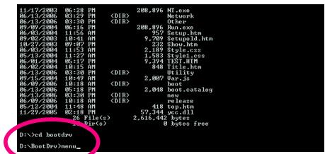
text_image
11/17/2003 06:28 PM 06/13/2006 01:29 PM 06/13/2006 02:30 PM 06/09/2004 06:10 PM 06/03/2004 11:56 AM 07/02/2003 10:43 PM 10/27/2003 09:07 PM 06/02/2004 11:53 PM 06/13/2004 11:27 PM 06/01/2004 05:17 PM 06/02/2004 10:15 PM 06/13/2006 03:38 PM 09/15/2004 10:40 PM 06/09/2006 10:18 PM 06/13/2006 05:18 PM 06/13/2006 03:38 PM 06/09/2006 10:18 PM 06/13/2004 11:48 AM 11/29/2005 02:18 PM 7% File(s) Dirc(s) 288,896 NT.exe Network Other Run.exe Setup.htm SetupOut.htm Style.css Style class TIST_HTM Tistor.htm Utility Var.js boot catalog release top.htm 52,344 sec.dll 2,616.442 bytes 8 bytes freeFigure 1
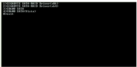
text_image
1>①CIGARBYTE SATA-RAID DriverFigure 2
(Note 1) For AHCI drives, installation of Windows Vista does not require you to install the SATA AHCI driver during the OS installation process.
(Note 2) For users without a startup disk:
Use an alternative system and insert the motherboard driver disk. From your optical drive folder, double click the MENU.exe file in the BootDrv folder (Figure 3). A command prompt window will open similar to that in Figure 2.
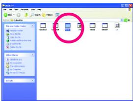
text_image
File Edit View Options Help File Edit View Tools Help File Edit View Tools Help File Edit View Tools Help File Edit View Tools Help File Edit View Tools Help File Edit View Tools Help File Edit View Tools Help File Edit View Tools Help File Edit View Tools Help File Edit View Tools Help File Edit View Tools Help File Edit View Tools Help File Edit View Tools Help File Edit View Tools Help File Edit View Tools Help File Edit View Tools Help File Edit View Tools Help File Use History File History File History File History File History File History File History File History File History File History File History File History File History File History File History File History File History File History File History File History File History File History File History File History File History File History File History File History File History File History File History File History File History File History File Historicity File Historicity File Historicity File Historicity File Historicity File Historicity File Historicity File Historicity File Historicity File Historicity File Historicity File Historicity File Historicity File Historicity File Historicity File Historicity File Historicity File Historicity File Historicity File Historicity File Historicity File Historicity File Historicity File Historicity File Historicity File HistoricitiesFigure 3
5-1-4 Installing the SATA RAID/AHCI Driver and Operating System
Now that you have prepared the SATA RAID/AHCI driver diskette and configured the required BIOS settings, you are ready to install Windows Vista/XP/2000 onto your hard drive(s). The following is an example of Windows XP and Vista installation.
A. Installing Windows XP
Step 1:
Restart your system to boot from the Windows XP setup disk and press
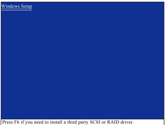
text_image
Windows Setup Press F6 if you need to install a third party SCSI or RAID driver.Figure 1
Step 2:
When a screen similar to that below appears, insert the floppy disk containing the SATA RAID/AHCI driver and press (Figure 2).
| Windows Setup |
| Setup could not determine the type of one or more mass storage devices installed in your system, or you have chosen to manually specify an adapter. Currently, Setup will load support for the following mass storage devices(s) |
| <none> |
| * To specify additional SCSI adapters, CD-ROM drives, or special disk controllers for use with Windows, including those for which you have a device support disk from a mass storage device manufacturer, press S. |
| * If you do not have any device support disks from a mass storage device manufacturer, or do not want to specify additional mass storage devices for use with Windows, press ENTER. |
| S=Specify Additional Device ENTER=Continue F3=Exit |
Figure 2
Step 3:
When Setup correctly recognizes the AMD SB600 SATA RAID/AHCI driver in the floppy disk, a controller menu similar to Figure 3 below will appear. Use the arrow keys to select ATI AHCI Compatible RAID Controller-x86 platform and press

text_image
Windows Setup You have chosen to configure a SCSI Adapter for use with Windows, using a device support disk provided by an adapter manufacturer. Select the SCSI Adapter you want from the following list, or press ESC to return to the previous screen. ATI AHCI Compatible RAID Controller-x86 platform ATI AHCI Compatible RAID Controller-x64 platform ENTER=Select F3=ExitFigure 3

If a message appears saying one or some file(s) cannot be found, please check the floppy disk or copy the correct SATA RAID/AHCI driver again from the motherboard driver disk.
When the screen as shown below appears, press
| Windows Setup |
| Setup will load support for the following mass storage device(s): |
| ATI AHCI Compatible RAID Controller-x86 platform |
| * To specify additional SCSI adapters, CD-ROM drives, or special disk controllers for use with Windows, including those for which you have a device support disk from a mass storage device manufacturer, press S. |
| * If you do not have any device support disks from a mass storage device manufacturer, or do not want to specify additional mass storage devices for use with Windows, press ENTER. |
| S=Specify Additional Device ENTER=Continue F3=Exit |
Figure 4
Step 3:
For GIGABYTE SATA2 SATA controller:
When Setup correctly recognizes the GIGABYTE SATA2 SATA RAID/AHCI driver in the floppy disk, a controller menu similar to Figure 5 below will appear. Use the arrow keys to select one of the items displayed and press
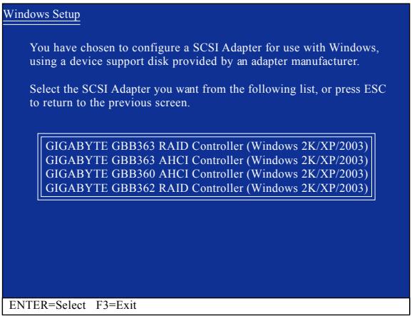
text_image
Windows Setup You have chosen to configure a SCSI Adapter for use with Windows, using a device support disk provided by an adapter manufacturer. Select the SCSI Adapter you want from the following list, or press ESC to return to the previous screen. GIGABYTE GBB363 RAID Controller (Windows 2K/XP/2003) GIGABYTE GBB363 AHCI Controller (Windows 2K/XP/2003) GIGABYTE GBB360 AHCI Controller (Windows 2K/XP/2003) GIGABYTE GBB362 RAID Controller (Windows 2K/XP/2003) ENTER=Select F3=ExitFigure 5

If a message appears saying one or some file(s) cannot be found, please check the floppy disk or copy the correct SATA RAID/AHCI driver again from the motherboard driver disk.
When the screen as shown below appears, press
| Windows Setup |
| Setup will load support for the following mass storage device(s): |
| GIGABYTE GBB363 RAID Controller (Windows 2K/XP/2003) |
| * To specify additional SCSI adapters, CD-ROM drives, or special disk controllers for use with Windows, including those for which you have a device support disk from a mass storage device manufacturer, press S. |
| * If you do not have any device support disks from a mass storage device manufacturer, or do not want to specify additional mass storage devices for use with Windows, press ENTER. |
| S=Specify Additional Device ENTER=Continue F3=Exit |
Figure 6
Step 4:
After the SATA RAID/AHCI driver installation is completed, you can proceed with the Windows XP installation.
| WindowsXP Professional Setup |
| Welcome to Setup. This port of the Setup program prepares Microsoft(R) Windows (R) XP to run on your computer. |
| To set up Windows XP now, press ENTER. |
| To repair a Windows XP installation using Recovery Console, press R. |
| To quit Setup without installing Windows XP, press F3. |
| Enter= Continue R=Repair F3=Exit |
Figure 7
B. Installing Windows Vista (Note)
(The procedure below assumes that only one RAID array exists in your system.)
AMD SB600 SATA controllers:
Step 1:
Restart your system to boot from the Windows Vista setup disk and perform standard OS installation steps. When a screen similar to that below appears (RAID hard drive will not be detected at this stage), select Load Driver. (Figure 8).
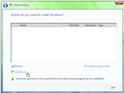
text_image
Where do you want to install Windows? Name Total Size Free Space Type Refresh Drive options (advanced) Load Driver No drives were found. Click Load Driver to provide a mass storage driver for installation. NextFigure 8
Step 2:
Specify the location where the driver is saved. Refer to the following two ways:
Method A:
Insert the motherboard driver disk into your system and browse to the following directory:
\Chipset\RS690\Vista\Packages\Drivers\SBDrv\SB6xx\RAID\LH
For Windows Vista 64-bit, browse to the LH64A folder.
Method B:
If you have copied the SATA RAID driver to a floppy disk following the instructions in "5-1-3," insert the floppy disk and browse to the LH (for Windows Vista 32-bit) or LH64A (for Windows Vista 64-bit) folder
(Figure 9).

text_image
Install Windows Select the driver to be installed. Browse for Folder Browse to the driver(s), and then click OK Computer Flash Disk Drive (A:) LHB44 CD Drive (D:) Boot (A:) OK Cancel Hide drivers that. Browse Rescan NextFigure 9
(Note) For AHCI drives, installation of Windows Vista does not require you to install the SATA AHCI driver during the OS installation process.
Step 3:
When a screen as shown in Figure 10 appears, select AMD AHCI Compatible RAID Controller and press Next.
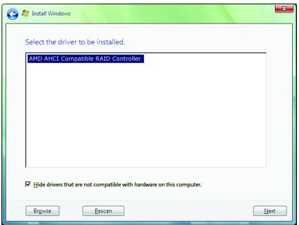
text_image
Install Windows Select the driver to be installed. AMD AHCI Compatible RAID Controller Hide drivers that are not compatible with hardware on this computer. Browse Bescan NextFigure 10
Step 4:
After the driver is loaded, the RAID drive will appear. Select the RAID drive and then press Next to continue the OS installation (Figure 11).
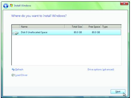
text_image
Where do you want to install Windows? Name Total Size Free Space Type Disk 0 Unallocated Space 80.0 GB 80.0 GB Refresh Drive options (advanced) Load Driver NextFigure 11
GIGABYTE SATA2 controllers:
Step 1:
Restart your system to boot from the Windows Vista setup disk and perform standard OS installation steps. When a screen similar to that below appears (RAID/AHCI hard drive(s) will not be detected at this stage), select Load Driver. (Figure 12).
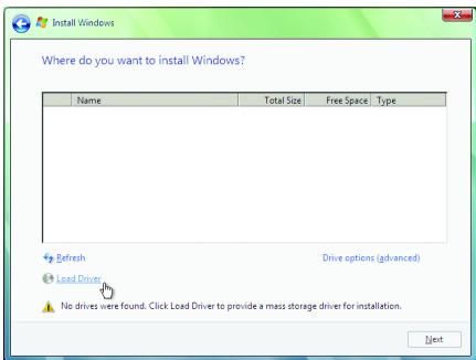
text_image
Where do you want to install Windows? Name Total Size Free Space Type Refresh Drive options (advanced) Load Driver No drives were found. Click Load Driver to provide a mass storage driver for installation. NextFigure 12
Step 2:
Specify the location where the driver is saved, such as your floppy disk (Figure 13).
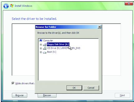
text_image
Select the driver to be installed. Browse for Folder Browse to the driver(s), and then click OK Computer Happy Disk Drive (A:) CD Drive (D:) LRMCFR BL_DVD Boot (N:) Hide drivers that: OK Cancel Browse Rescan NextFigure 13
Step 3:
When a screen as shown in Figure 14 appears, select GIGABYTE GBB36X Controller and press Next.
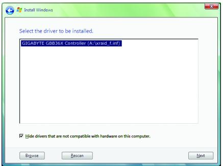
text_image
Install Windows Select the driver to be installed. GIGABYTE GBB36X Controller (A:\vvasd_f.mf) Hide drivers that are not compatible with hardware on this computer. Browse Descan NextFigure 14
Step 4:
After the driver is loaded, select the RAID/AHCI drive(s) where you want to install the operating system and then press Next to continue the OS installation (Figure 15).

text_image
Where do you want to install Windows? Name Total Size Free Space Type Disk 0 Unallocated Space 80.0 GB 80.0 GB Refresh Drive options (advanced) Load Driver NextFigure 15
5-2 Configuring Audio Input and Output
5-2-1 Configuring 2/4/5.1/7.1-Channel Audio
The motherboard provides six audio jacks on the back panel which support 2/4/5.1/7.1-channel audio. The picture to the right shows the default audio jack assignments.
The integrated HD (High Definition) audio provides jack retasking capability that allows the user to change the function for each jack through the audio driver.
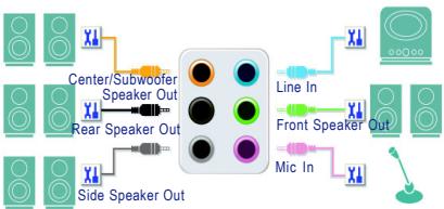
flowchart
graph TD
    A["Speaker Out"] --> B["Center/Subwoofer"]
    A --> C["Rear Speaker Out"]
    A --> D["Side Speaker Out"]
    B --> E["Line In"]
    C --> F["Front Speaker Out"]
    D --> G["Mic In"]
For example, in a 4-channel audio configuration, if a Rear speaker is plugged into the default Center/Subwoofer speaker out jack, you can retask the Center/Subwoofer speaker out jack to be Rear speaker out.

- To install a microphone, connect your microphone to the Mic in or Line in jack and manually configure the jack for microphone functionality.
- If your front panel audio supports Intel HD Audio standard, you can have both the front and back panel audio connectors active simultaneously.
High Definition Audio (HD Audio)
HD Audio includes multiple high quality digital-to-analog converters (DACs) that support 48KHz sampling rate. HD Audio features multistreaming capabilities that allow multiple audio streams (in and out) to be simultaneously processed. For example, users can listen to MP3 music, have an Internet chat, make a telephone call over the Internet, and etc. all at the same time.
A. Configuring Speakers:
(The following instructions use Windows XP as the example operating system.)
Step 1:
After installing the audio driver, the Audio Manager icon will appear in your system tray. Double-click the icon to access the Audio Control Panel.
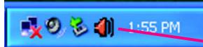
text_image
1:55 PM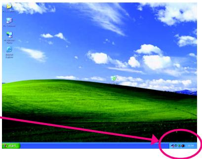
text_image
Start Start Menu
Before installing the audio driver, make sure the "Microsoft UAA Bus driver for High Definition Audio" has been installed from the motherboard driver disk and your operating system has been updated with the latest Service Pack for Windows.
(Note) 2/4/5.1/7.1- Channel Audio Configurations:
Refer to the following for multi-channel speaker configurations.
• 2 -channel audio: Headphone or Line out.
• 4- channel audio: Front speaker out and Rear speaker out.
• 5.1- channel audio: Front speaker out, Rear speaker out, and Center/Subwoofer speaker out.
• 7.1 -channel audio: Front speaker out, Rear speaker out, Center/Subwoofer speaker out, and Side speaker out.
Step 2:
Click the Audio I/O tab. In the speaker list on the left, select 2CH Speaker, 4CH Speaker, 6CH Speaker, or 8CH Speaker according to the type of speaker configuration you wish to set up.
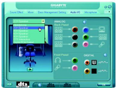
text_image
GIGABYTE Sound Effect Mixer Bass Management Setting Audio I/O Microphone SCH Speaker Analogg Back Panel 800 800 800 800 Front Panel Digital 800 800 800 800 800 800 800 800 800 800 800 800 800 800 800 800 800 800 800 800 800 800 800 800 800 801 801 801 801 801 801 801 801 801 801 801 801 801 801 801 801 801 801 801 801 801 801 801 801 801 802 802 802 802 802 802 802 802 802 802 802 802 802 802 802 802 802 802 802 802 802 802 802 802 802 803 803 803 803 803 803 803 803 803 803 803 803 803 803 803 803 803 803 803 803 803 803 803 803 803 804 804 804 804 804 804 804 804 804 804 804 804 804 804 804 804 804 804 804 804 804 804 804 804 804Step 3:
Everytime you connect an audio device to an audio jack, the Connected device box appears. Select the device according to the type of device you connect. Then click OK to complete the configuration.
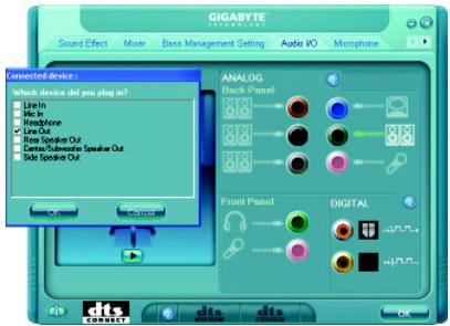
text_image
GIGABYTE Sound Effect Mixer Base Management Setting Audio I/O Microphone Connected Device: Which device did you plug in? Live In In In Headphone Line Out Real Speaker Out Carte/Subordinate Speaker Out Side Speaker Out Analog Back Panel Front Panel DIGITAL OK CONNECTB. Configuring Sound Effect:
You may configure an audio environment on the Sound Effect tab.
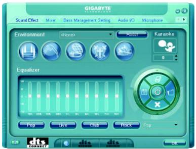
text_image
GIGABYTE Sound Effect Mixer Bass Management Setting Audio IO Microphone Environment < img src> Focal Karaoke Equalizer Pop Live Club Roll Pop Clk DIS DISC. Configuring AC'97 Audio:
If you want to connect an AC'97 front panel audio module, click the tool icon on the Audio I/O tab On the Global Connector Settings box, select the Disable front panel jack detection check box. Click OK to activate the AC'97 functionality.
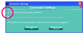
text_image
Connector Settings ✓ Enable front panel lock detection ✓ Enable rear panel call when front/headphone plugged in ✓ Enable auto popup dialog when device has been plugged in OK Cancel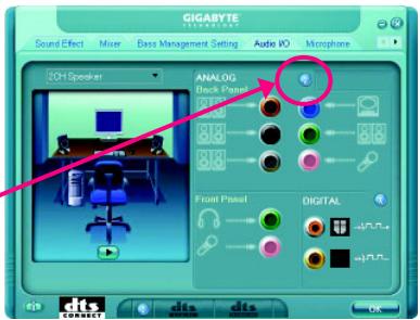
text_image
GIGABYTE Sound Effect Mixer Voice Management Setting Audio IO Microphone 2OH Speaker ANALOG Blank Panel 88 88 88 Front Panel DIGITAL OK CITS CONNECT
When using an AC'97 front panel audio module, you can only have audio signals present on either the front or the back panel audio connections, but not both at the same time.
5-2-2 Installing the S/PDIF In Cable (Optional)
The S/PDIF in cable provides S/PDIF in functionality.
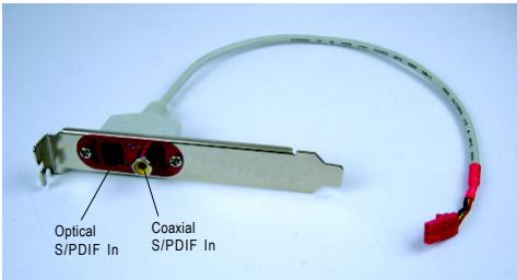
text_image
Optical S/PDIF In Coaxial S/PDIF InS/PDIF In:
The S/PDIF in jacks allow you to input digital audio signals to the computer for audio processing.
A. Installing the S/PDIF In Cable:
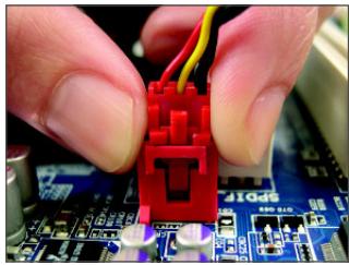
natural_image
Close-up of hands holding a red plastic connector with yellow wires, partially installed on a circuit board (no visible text or symbols)Step 1:
First, attach the connector at the end of the cable to the SPDIF_IN header on your motherboard.
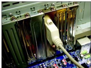
natural_image
Close-up of an electronic device with a cable inserted into a socket, showing internal components and wiring (no visible text or symbols)Step 2:
Secure the metal bracket to the chassis back panel with a screw.
S/PDIF Out:
The S/PDIF out jacks can transmit audio signals to an external decoder for decoding to get the best audio quality.
B. Conneting a S/PDIF out Cable
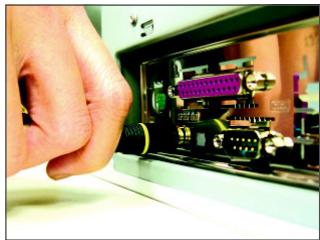
natural_image
Close-up of a hand inserting a CD into a device (no visible text or symbols)S/PDIF Coaxial Cable
Connect a S/PDIF coaxial cable or a S/PDIF optical cable (either one) to an external decoder for transmitting the S/PDIF digital audio signals.
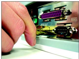
natural_image
Close-up of a hand inserting a CD-ROM into an electronic device (no visible text or symbols)S/PDIF Optical Cable
C. Configuring S/PDIF out:
Click the tool icon in the DIGITAL section. In the S/PDIF In/Out Settings dialog box, select an output sampling rate and select (or disable) the output source. Click OK to complete the configuration.
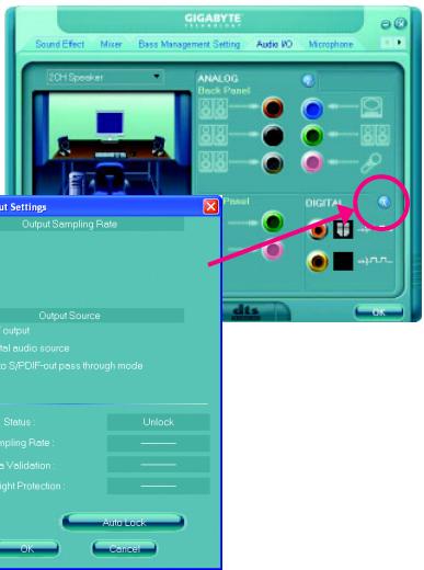
text_image
GIGABYTE Sound Effect Mixer Bass Management Setting Audio IO Microphone 20H Speaker ANALOG Block Panel Digital Panel Output Sampling Rate Output Source output set audio source S/PDIF-out pass through mode Status: Unlock Sampling Rate: Validation: Light Protection: Auto Lock OK Cancel
text_image
dts Connect5-2-3 Enabling the DTS (Digital Theater Systems) Function
Before DTS is enabled, you would get only 2-channel output signals (from the front speakers) when playing 2-channel music. You must play 4-, 5.1-, or 7.1- channel music sources to produce 4-, 5.1-, or 7.1- channel audio effects.
With DTS enabled, the system will transform two-channel stereo source material into multi-channel audio output, creating a virtual surround sound environment ^(Note) .
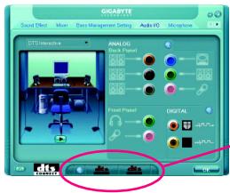
text_image
GIGARTE Sound Effect Max Tens Management Settings Audio HG Machette GTS Interactive ANALOG Stock Panel Front-Panel DIGITAL 0.0000000000000000000000000000000000000000000000000000000000000000000000000000000000000000000000000 12345678888888888888888888888888888888888888888888888888888888888888888888888888888888888888888After installing the audio driver, at the center bottom of the Audio Control Panel, you should find the DTS control button as shown below:

text_image
dts SREDI dts INTUANGAIDTS control button
- : This button provides you more controls over "dts NEO:PC".

Music Mode ; Cinema Mode
- dts NEO : PC" :
Press this button to enable or disable the dts NEO : PC function.
Enabling dts NEO : PC allows the system to transform ordinary 2-channel stereo content into 4-, 5.1-, or 7.1- channel surround sound, depending on your speaker configurations.
- "dts INTERACTIVE":
If your surround sound system is connected via an external decoder, click the Audio I/O tab in the Audio Control Panel. Either click DTS Interactive in the upper left list or click the dts INTERAC-
TIVE button at the center bottom of the Audio Control Panel. And click the dts NEO : PC button. The system will then simulate 5.1-channel surround sound playback from two-channel content.
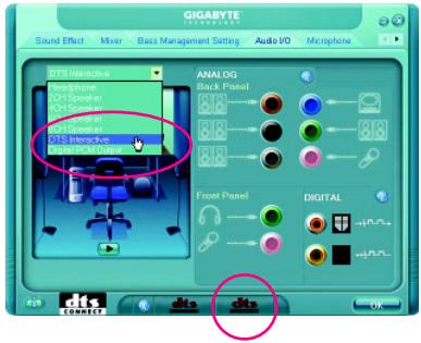
text_image
GIGABYTE Sound Effect Mirror Bass Management Setting Audio I/O Microphone DTI Interactive Pacqnone SOI Speaker SOI Speaker DOS Speaker DTI Performer Digital DM Output ANALOG Back Panel 8.8 8.8 8.8 Front Panel DIGITAL OK(Note) When DTS Interactive is enabled, only digital auio output (S/PDIF) is working, and you will not hear sound from analog speaker or headphone.
4. Digital PCM Output Setup:
In the Audio Control Panel, click the Audio I/O tab. In the upper left list, click Digital PCM Output.
Enable this function to allow digital audio sources that are not digitally processed by DTS encoding to be output from the S/PDIF OUT.
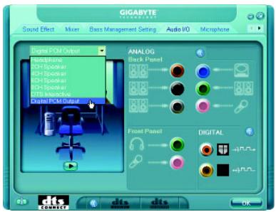
text_image
GIGABYTE Sound Effect Mixer Base Management Setting Audio I/O Microphone Digital PCM Output Headframe 4CH Speaker 4CH Speaker 4CH Speaker CTS Interactive Digital PCM Output ANALOG Back Panel Front Panel DIGITAL OK5-2-4 Configuring Microphone Recording
Step 1:
After installing the audio driver, the Audio Manager icon will appear in your system tray. Double-click the icon to access the Audio Control Panel.
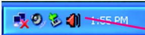
text_image
1:55 PM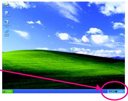
Connect your microphone to the Mic in jack (pink) on the back panel or the Line in jack on the front panel. Then configure the jack for microphone functionality.
Note: The microphone functions on the front panel and back panel cannot be used at the same time.
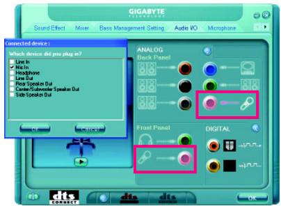
text_image
GIGABYTE Sound Effect Mixer Days Management Setting Audio I/O Microphone Connected device: Which device did you plug in? Line In Line Out Headphone Line Splitter Dui Center Subwoofer Speaker Dui Side Speaker Dui ANALOG Back Panel Front Panel DIGITAL dits cdisStep 3:
Locate the Volume icon 📋 in your system tray and click it to open the volume control panel

text_image
1:55 PM
To hear the sound being recorded during the recording process when using the microphone function on the front panel, do not select the Mute check box under Front Pink In or Front Green In in Master Volume. It is recommended that you set the volume at a middle level.
To hear the sound being recorded during the recording process when using the microphone function on the back panel, do not select the Mute check box under Rear Pink In in Master Volume. It is recommended that you set the volume at its middle level.
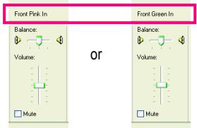
text_image
Front Pink In Balance: Volume: Mute or Front Green In Balance: Volume: Mute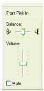
(Note)
If you cannot find the volume control options you need in Master Volume, go to the Options menu and then choose Properties. Select the volume control options you wish to show and click OK to complete.
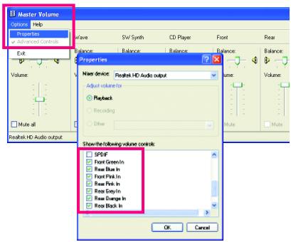
text_image
Master Volume Options Help Properties Advanced Control Wave SW Synth CD Player Front Rear Balance: Balance: Balance: Balance: Volume: Volume: Volume: Volume: Name device: Playback HD Audio output Adjust volume for Playback Recording Other Show the following volume control: SPDF Front Green In Real Blue In Front Pink In Real Pink In Real Grey In Real Green In Real Green In Real Black In OK CancelStep 5:
Next, while in Master Volume, go to Options and click Properties. In the Mixer device list, select Realtek HD Audio Input. Then set the recording sound level properly. Do NOT mute the recording sound, or you will not hear any sound when playing back the recording you just made.
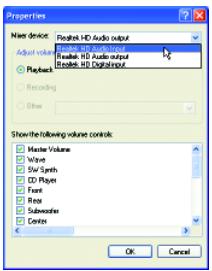
text_image
Properties Main device: Portable HD Audio output Adjust volume Recheck Recheck HD Audio output Recheck HD Digital output Recheck Recheck Show the following volume controls: Master Volume Wave SW Synth CD Player Frost Fire Subwoofer Center OK CancelSelect Realtek HD Audio Input in the Mixer device list
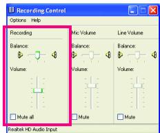
text_image
Recording Control Options Help Recording Balance: Volume: Mute all Mic Volume Balance: Volume: Mute Line Volume Balance: Volume: Mute Realtek HD Audio InputRecording Control
Step 6:
To raise the recording and playing sound for the microphone, go to Options in Master Volume and select Advanced Controls. Click the Advanced button under a volume control option (e.g. Front Green In, Front Pink In). In the Other Controls field, select the 1 Microphone Boost check box.
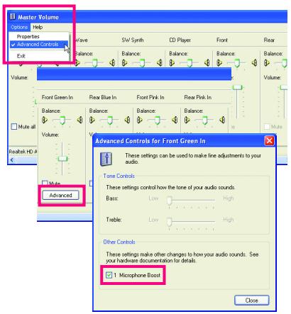
text_image
Master Volume Options Help Properties Advanced Controls Exit Wave SW Synth CD Player Front Rear Balance: Balance: Balance: Balance: Volume: Volume: Front Green In Rear Blue In Front Pink In Rear Pink In Balance: Balance: Balance: Balance: Volume: Volume: Multi all Realtek HD A Advanced Advanced Controls for Front Green In These settings can be used to make fine adjustments to your audio. Tone Controls: These settings control how the tone of your audio sounds. Bass: Low High Treble: Low High Other Controls: These settings make other changes to how your audio sounds. See your hardware documentation for details. ✓ Microphone Boost CloseStep 7:
After completion, click Start, point to All Programs, point to Accessories, point to Entertainment, and then click Sound Recorder to begin the sound recording.
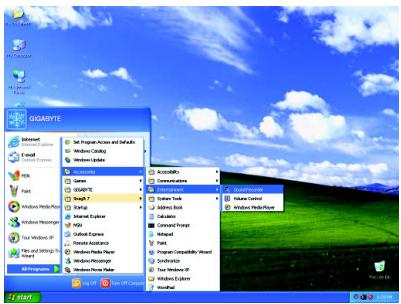
text_image
GIGASYTE Smart Plus Smart Plus Active and Safe Windows Compute Windows Update Accessories SmartIcon Smart Link Smart Locks Smart System Smart Security Smart Security Smart Security Smart Security Smart Security Smart Security Smart Security Smart Security Smart Security Smart Security Smart Security Smart Security Smart Security Smart Security Smart Security Smart Security Smart Security Smart Security Smart Security Smart Security Smart Security Smart Security Smart Security Smart Security Smart Security Smart Security Smart Security Smart Security Smart Security Smart Security Smart Security Smart Security Smart Security Smart Security5-2-5 Using the Sound Recorder
Recording the Sound:
- Make sure you have connected the audio input device (e.g. microphone) to the computer.
- On the File menu, choose New.
- To record a sound file, click the Recording button ☐.
- To stop the recording, click the Stop button ■. Be sure to save the recording upon completion.
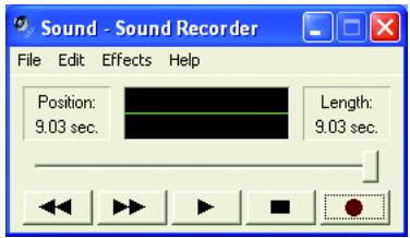
text_image
Sound - Sound Recorder File Edit Effects Help Position: 9.03 sec. Length: 9.03 sec.Playing the Sound:
- On the File menu, choose Open.
- In the Open dialog box, select the sound (.wav) file you wish to play.
- To play a sound file, click the Play button ▶.
- To stop playing, click the Stop button ■.
- You may use the Fast Forward button ← to move to the beginning of a file or the Fast Backward button ▶ to the end.
5-3 Troubleshooting
5-3-1 Frequently Asked Questions
To read more FAQs for your motherboard, please go to the Support\Motherboard\FAQ page on GIGABYTE's website.
Q: In the BIOS Setup program, why are some BIOS options missing?
A: Some advanced options are hidden in the BIOS Setup program. Press
Q: Why is the light of my keyboard/optical mouse still on after the computer shuts down?
A: Some motherboard provides a small amount of standby power after the computer shuts down and that's why the light is still on.
Q: How do I clear the CMOS values?
A: If your motherboard has a clearing CMOS jumper, refer to the instructions on the CLR_CMOS jumper in Chapter 1 to short the jumper to clear the CMOS values. If your board doesn't have this jumper, refer to the instructions on the motherboard battery in Chapter 1. You can temporarily remove the battery from the battery holder to stop supplying power to the CMOS, which will clear the CMOS values after about one minute. Refer to the steps below:
Steps:
- Turn off your computer and unplug the power cord.
- Gently remove the battery from the battery holder and wait for one minute.
(Or use a metal object like a screwdriver to touch the positive and negative terminals of the battery holder, making them short for 5 seconds.)
- Replace the battery.
- Plug in the power cord and restart your computer.
- Press
to enter BIOS Setup. Select "Load Fail-Safe Defaults" (or "Load Optimized Defaults") to load BIOS default settings. - Saves changes and exit BIOS Setup (select "Save & Exit Setup") to restart your computer.
Q: Why do I still get a weak sound even though I have turned my speaker to the maximum volume?
A: Make sure your speaker is equipped with an internal amplifier. If not, try a speaker with power/amplifier.
Q: What do the beeps emitted during the POST mean?
A: The following Award BIOS beep code descriptions may help you identify possible computer problems. (For reference only.)
1 short: System boots successfully
2 short: CMOS setting error
1 long, 1 short: Memory or motherboard error
1 long, 2 short: Monitor or graphics card error
1 long, 3 short: Keyboard error
1 long, 9 short: BIOS ROM error
Continuous long beeps: Graphics card not inserted properly
Continuous short beeps: Power error
5-3-2 Troubleshooting Procedure
If you encounter any troubles during system startup, follow the troubleshooting procedure below to solve the problem.
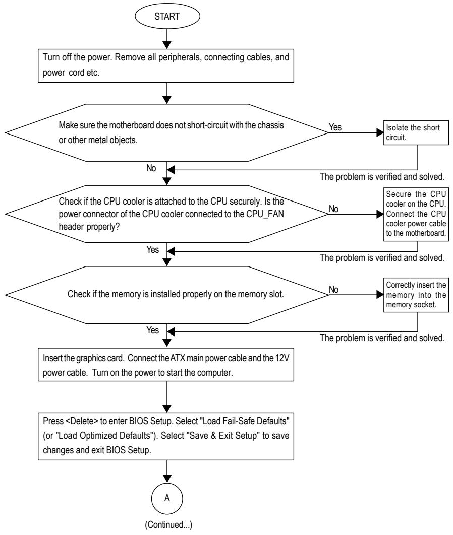
flowchart
graph TD
A["START"] --> B["Turn off the power. Remove all peripherals, connecting cables, and power cord etc."]
B --> C{Make sure the motherboard does not short-circuit with the chassis or other metal objects.}
C -->|Yes| D["Isolate the short circuit."]
C -->|No| E{Check if the CPU cooler is attached to the CPU securely. Is the power connector of the CPU cooler connected to the CPU_FAN header properly?}
E -->|No| F["Secure the CPU cooler on the CPU. Connect the CPU cooler power cable to the motherboard."]
E -->|Yes| G{Check if the memory is installed properly on the memory slot.}
G -->|No| H["Correctly insert the memory into the memory socket."]
G -->|Yes| I["Insert the graphics card. Connect the ATX main power cable and the 12V power cable. Turn on the power to start the computer."]
I --> J["Press <Delete> to enter BIOS Setup. Select "Load Fail-Safe Defaults" (or "Load Optimized Defaults"). Select "Save & Exit Setup" to save changes and exit BIOS Setup."]
J --> K["A\n(Continued...)"]
D --> L["The problem is verified and solved."]
F --> M["The problem is verified and solved."]
H --> N["The problem is verified and solved."]
L --> O["The problem is verified and solved."]
M --> O
N --> O
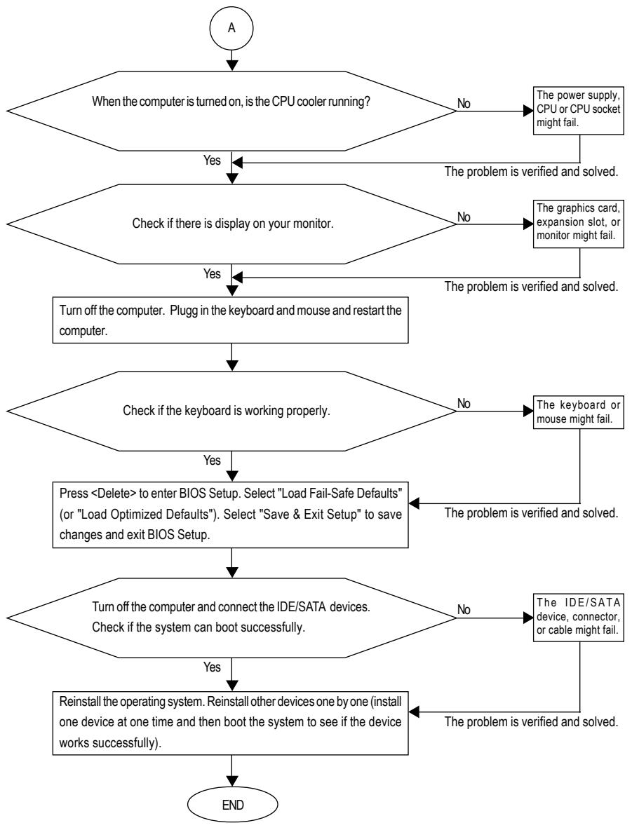
flowchart
graph TD
A["A"] --> B{When the computer is turned on, is the CPU cooler running?}
B -->|No| C["The power supply, CPU or CPU socket might fail."]
B -->|Yes| D{Check if there is display on your monitor.}
D -->|No| E["The graphics card, expansion slot, or monitor might fail."]
D -->|Yes| F["Turn off the computer. Plugg in the keyboard and mouse and restart the computer."]
F --> G{Check if the keyboard is working properly.}
G -->|No| H["The keyboard or mouse might fail."]
G -->|Yes| I["Press <Delete> to enter BIOS Setup. Select "Load Fail-Safe Defaults" (or "Load Optimized Defaults"). Select "Save & Exit Setup" to save changes and exit BIOS Setup."]
I --> J{Turn off the computer and connect the IDE/SATA devices. Check if the system can boot successfully.}
J -->|No| K["The IDE/SATA device, connector, or cable might fail."]
J -->|Yes| L["Reinstall the operating system. Reinstall other devices one by one (install one device at one time and then boot the system to see if the device works successfully)."]
K --> M["End"]
L --> M
M --> N["END"]

If the procedure above is unable to solve your problem, contact the place of purchase or local dealer for help. Or go to the Support\Technical Service Zone page to submit your question. Our customer service staff will reply you as soon as possible.
Regulatory Statements
Regulatory Notices
This document must not be copied without our written permission, and the contents there of must not be imparted to a third party nor be used for any unauthorized purpose. Contravention will be prosecuted. We believe that the information contained herein was accurate in all respects at the time of printing. GIGABYTE cannot, however, assume any responsibility for errors or omissions in this text. Also note that the information in this document is subject to change without notice and should not be construed as a commitment by GIGABYTE.
Our Commitment to Preserving the Environment
In addition to high-efficiency performance, all GIGABYTE motherboards fulfill European Union regulations for RoHS (Restriction of Certain Hazardous Substances in Electrical and Electronic Equipment) and WEEE (Waste Electrical and Electronic Equipment) environmental directives, as well as most major worldwide safety requirements. To prevent releases of harmful substances into the environment and to maximize the use of our natural resources, GIGABYTE provides the following information on how you can responsibly recycle or reuse most of the materials in your "end of life" product.
Restriction of Hazardous Substances (RoHS) Directive Statement
GIGABYTE products have not intended to add and safe from hazardous substances (Cd, Pb, Hg, Cr+6, PBDE and PBB). The parts and components have been carefully selected to meet RoHS requirement. Moreover, we at GIGABYTE are continuing our efforts to develop products that do not use internationally banned toxic chemicals.
Waste Electrical & Electronic Equipment (WEEE) Directive Statement
GIGABYTE will fulfill the national laws as interpreted from the 2002/96/EC WEEE (Waste Electrical and Electronic Equipment) directive. The WEEE Directive specifies the treatment, collection, recycling and disposal of electric and electronic devices and their components. Under the Directive, used equipment must be marked, collected separately, and disposed of properly.
WEEE Symbol Statement

The symbol shown below is on the product or on its packaging, which indicates that this product must not be disposed of with other waste. Instead, the device should be taken to the waste collection centers for activation of the treatment, collection, recycling and disposal procedure. The separate collection and recycling of your waste equipment at the time of disposal will help to conserve natural resources and ensure that it is recycled in a manner that protects human health and the environment. For more information about where you can drop off your waste equipment for recycling, please contact your local government office, your household waste disposal service or where you purchased the product for details of environmentally safe recycling.
When your electrical or electronic equipment is no longer useful to you, "take it back" to your local or regional waste collection administration for recycling.
If you need further assistance in recycling, reusing in your "end of life" product, you may contact us at the Customer Care number listed in your product's user's manual and we will be glad to help you with your effort.
Finally, we suggest that you practice other environmentally friendly actions by understanding and using the energy-saving features of this product (where applicable), recycling the inner and outer packaging (including shipping containers) this product was delivered in, and by disposing of or recycling used batteries properly. With your help, we can reduce the amount of natural resources needed to produce electrical and electronic equipment, minimize the use of landfills for the disposal of "end of life" products, and generally improve our quality of life by ensuring that potentially hazardous substances are not released into the environment and are disposed of properly.
China Restriction of Hazardous Substances Table
The following table is supplied in compliance with China's Restriction of Hazardous Substances (China RoHS) requirements:

text_image
10Management Methods on Control of Pollution from Electronic Information Products
(China RoHS Declaration)
• Taiwan (Headquarters)
GIGA-BYTE TECHNOLOGY CO., LTD.
Address: No.6, Bau Chiang Road, Hsin-Tien,
Taipei 231, Taiwan
TEL: +886-2-8912-4888
FAX: +886-2-8912-4003
Tech. and Non-Tech. Support (Sales/Marketing):
G.B.T. TECHNOLOGY TRADING GMBH
WEB address : http://www.gigabyte.de
U.K.
G.B.T. TECH. CO., LTD.
WEB address : http://www.giga-byte.co.uk
• The Netherlands
GIGA-BYTE TECHNOLOGY B.V.
WEB address : http://www.giga-byte.nl
- Sweden
WEB address : http://www.gigabyte.se
- France
GIGABYTE TECHNOLOGY FRANCE
WEB address : http://www.gigabyte.fr
Italy
WEB address : http://www.giga-byte.it
- Spain
GIGA-BYTE SPAIN
WEB address : http://www.giga-byte.es
- Czech Republic
Representative Office Of GIGA-BYTE Technology Co., Ltd. in CZECH REPUBLIC
WEB address : http://www.gigabyte.cz
- Turkey
Representative Office Of GIGA-BYTE Technology Co., Ltd. in TURKEY
WEB address : http://www.gigabyte.com.tr
Russia
Moscow Representative Office Of GIGA-BYTE Technology Co., Ltd.
WEB address : http://www.gigabyte.ru
- Latvia
GIGA-BYTE Latvia
WEB address : http://www.gigabyte.lv
- Poland
Office of GIGA-BYTE TECHNOLOGY Co., Ltd. in POLAND WEB address : http://www.gigabyte.pl
- Ukraine
WEB address : http://www.giga-byte.com.ua
- Romania
Representative Office Of GIGA-BYTE Technology Co., Ltd. in Romania
WEB address : http://www.gigabyte.com.ro
• Serbia & Montenegro
Representative Office Of GIGA-BYTE Technology Co., Ltd. in SERBIA & MONTENEGRO
WEB address : http://www.gigabyte.co.yu
You may go to the GIGABYTE website, select your language in the language list on the top right corner of the website.
• GIGABYTE Global Service System
GIGABYTE

GTS
Global Technical Service
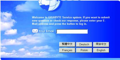
text_image
Welcome to GIGABYTE Service system, If you want to submit new question or check our response, please enter your E- Mail address and press the button to log in. Your Email : 繁體中文 Deutsch 简体中文 Français Polski EnglishTo submit a technical or non-technical (Sales/Marketing) question, please link to :
Then select your language to enter the system.