GWA720KOR - Basket Pelgrim - Free user manual and instructions
Find the device manual for free GWA720KOR Pelgrim in PDF.

User questions about GWA720KOR Pelgrim
0 question about this device. Answer the ones you know or ask your own.
Ask a new question about this device
Download the instructions for your Basket in PDF format for free! Find your manual GWA720KOR - Pelgrim and take your electronic device back in hand. On this page are published all the documents necessary for the use of your device. GWA720KOR by Pelgrim.
USER MANUAL GWA720KOR Pelgrim
The appliance identification card is located on the inside of the appliance.
Stick the appliance identification card here.
When contacting the service department,
have the complete type number to hand
You will find the addresses and phone numbers of the service organisation on the guarantee cents.
natural_image
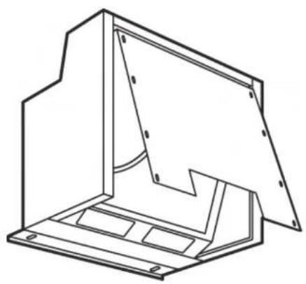
Technical line drawing of a mechanical housing or enclosure with internal components (no text or symbols)MWA130
GWA720
GWA810
Pelgrim
Handleiding
Notice d'utilisation - Anleitung - Manual
NL
Handleiding 3-12
FR
text_image
Technical diagram of a 3D geometric structure with numbered components, likely illustrating a mechanical or architectural assembly.

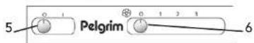
Bedieningsknoppen
text_image
15mm 15mm 15mm N1 15mm N2 N23 Installatie

text_image
Technical diagram showing mechanical assembly with labeled components R and Q, including a magnified view of a device with internal components.3 Installatie
text_image
Ø 2,5mm x 6mm max N3 K 6mm4 Onderhoud


text_image
Technical diagram showing two 3D geometric shapes with numbered annotations, likely illustrating a mechanical or architectural component.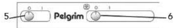
Boutons de commande
text_image
15mm 18mm 19mm N1 12mm N2 N23 Installation

text_image
Technical diagram showing mechanical assembly with labeled components R and Q, including a magnified view of a device with internal components.3 Installation
text_image
Ø 2,5mm x 6mm max N3 K 6mm
natural_image
Pure technical line drawing of a mechanical component or housing without any text, numbers, or symbols4 Entretien

text_image
Technical diagram showing two 3D geometric shapes with numbered annotations, likely illustrating a mechanical or architectural component.

Bedienschalter
text_image
10mm 15mm 10mm N1 45mm N2 N23 Installation

text_image
Technical diagram showing mechanical assembly with labeled components R and Q, including spring-loaded parts and a close-up of a mechanical component.3 Installation

text_image
Ø 2,5mm x 6mm max N3 K 6mm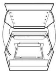
natural_image
Pure technical line drawing of a mechanical component or housing without any text, numbers, or symbols4 Wartung


1 Equipment description and use 34
2 Safety
2.1 What you need to take into account 35
2.2 Exhaust circuit 36
3 Installation
3.1 General 37
3.2 Mounting the exhaust hood on the side walls 38
3.3 Mounting the exhaust hood on the back wall 39
3.4 Mounting of the panel door 40
4 Maintenance
4.1 Cleaning 41
4.2 Cleaning and replacing the grease filters 41
4.3 Replacing carbon filters 41
4.4 Removing and placing the door 41
5 Appendice
1 Equipment description and use
Appliance description
1 - Moisture collector
2 - Grease filters
3 - Control panel
4 - Lighting

text_image
Technical diagram showing two 3D geometric shapes with numbered components, likely illustrating a mechanical or architectural assembly.

Controls
5 - Lighting switch
6 - Switch for electrical flap or speed regulator fan
Depending on the quantity of moisture you can choose a higher or lower position. Start the exhaust hood 5 minutes before cooking. Leave the exhaust on after cooking for another 15 minutes.
When an exhaust hood is connected to a central exhaust circuit you are only able to put the lights on and off and to open and close the electrical flap.
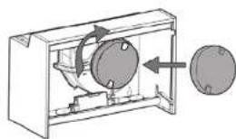
Apply carbon filter (only in case of re-circulation)
Place the carbon filter in the middle on the motor housing cap and turn it to the right one full turn.
Introduction
When you read this users manual you will be quickly informed of all the options the appliance offers you. You will be informed of safety measures and maintenance of the appliance.
Keep this users manual and the installation guide. This will be of use for any user of this appliance.
2 Safety
2.1 What you need to take into account

Attention! Make sure the appliance is installed by an authorised installer (see "Installation" chapter). Do not connect the appliance to the flow network before completing the installation.
- Connect the appliance in accordance with the applicable regulations in your area.
• We advise you to wear protective work gloves during the installation of the exhaust hood due to possible sharp edges. - The appliance has been manufactured in accordance with the latest safety standards. However we do advise that mentally handicapped, disabled or retarded individuals do not use this appliance without the proper supervision of a competent person. The same applies to children.
- Never use the exhaust hood when the grease filters have not been properly installed!
- Do not lean against the exhaust hood.
- Make sure there is sufficient circulation when you use the exhaust hood on a gas cooker.
- The exhaust exit must never be connected to a smoke duct which is also used for other heating appliances.
- Never flambé under the exhaust hood and always clean the filters on time. Frying needs to be done under constant supervision to prevent the heated fat from catching fire.
- The exhaust hood needs to be cleaned regularly (at least once a month) on the inside as well as on the outside. When the filters are insufficiently cleaned or replaced, this will result in a fire hazard.
- If the connection cable becomes damaged, it should be replaced by the manufacturer's service department or by a person with equivalent qualifications, in order to prevent dangerous situations from arising.
- First disconnect the appliance from the socket when you replace the lights! Only use identical lamps with the wattage indicated. Only use the exhaust hood with lamps installed to reduce the risk of electrical shock.
- The filter grid can be removed by pulling it straight down. Do this by using both hands.
- The filter grid with grease filter is becoming hot during operation. Wait a minimum of 30 minutes after cooking before cleaning it.
2 Safety
- The main current must be switched off during reparation or cleaning. Remove the plug from the mains current or turn the switch in the meter cupboard to zero.
- Grease and oil are flammable when they are overheated. Stay in the vicinity of the cooker when preparing food.
This appliance is marked accordance with European guideline regarding the disposal of electrical and electronic appliances (AEEA). This product should be disposed of in accordance with the local environmental regulations for disposal of waste. For further information regarding the treatment, recovery and recycling of this product you can contact your local council, the household waste service or the shop where you purchased the product.
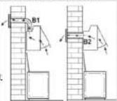
2.2 Exhaust circuit
Depending on the model there are three possible ways to connect this exhaust hood.
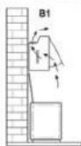
- As exhaust hood on an exhaust duct. The cooking moisture that is sucked in and filtered is transported upwards (B1) or, depending on your choice, to the back (B2) and then to the outside. This is the best method!
- As a re-circulation exhaust hood (excluding motorless exhaust hoods). The grease and odour will be filtered out of the cooking moisture that is sucked in. The air that is sucked in is not transported away but blown back into the kitchen (B1). You will need to fit a carbon filter.
Attention! The carbon filter needs to be ordered separately.
- As a motorless exhaust hood. This model is only suitable for installation in combination with a mechanical ventilation circuit.
3 Installation
3.1 General
The connection of this appliance to the electric mains must be done by an authorised installer who is knowledgeable of the safety precautions and will carry them out. The appliance is in compliance with European guidelines.
Important to know:
- The distance between the lowest point of the exhaust hood and the gas cooker should be at least 70 cm. When using an electrical cooker this distance should be at least 50 cm.
- The mains voltage indicated on the dataplate on the appliance should be identical to the mains voltage of the house installation.
- No other appliance must be connected to the duct (such as a hot water heater or a heater) when the exhaust hood is connected to an existing exhaust duct.
- Please follow the local guidelines with regard to the ventilation of gas appliances.
- The exhaust will operate best when the exhaust pipe is as short and as straight as possible.
- Check before starting drilling whether there is/are no installation pipe(s) present.
- The connection pipe to the exhaust hood has a diameter of 125 mm or 150 mm. We recommend that the exhaust pipe has the same diameter.
- The enclosed installation materials are suitable for reinforced concrete and brick walls. Special plugs and screws may be required for other materials.
3 Installation

Mounting preparation
Choose the exhaust outlet (B1 of B2) and open it up by removing the perforated plate. Attach the plastic connecting piece on the opened exhaust outlet. The connecting piece has a bayonet joint.

text_image
B1 B2 B1 B2 B1 B2 B1 B2 B23.2 Mounting the exhaust hood on the side walls
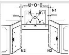
Check whether the cabinets are secure. Use drilling jig N2 to determine the mounting holes. The top of the jig is equal to the top of the exhaust hood. The top of the jig is at the same level as the exhaust hood without panel door.
text_image
15mm 15mm 15mm N1 15mm N2 N23 Installation
Drill the mounting holes in the cabinets.
Filling pieces are provided in order to mount the exhaust hood to the cabinets to a thickness of 16 mm. The supplied angle steel (Q) can be used to fill in the space at the back between the exhaust hood and the wall.
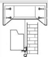
3.3 Mounting the exhaust hood onto the back wall
Use drilling jig N1 to determine the mounting holes. The top of the jig is equal to the top of the exhaust hood.
Drill the holes and attach the wall brackets (R) to the wall by using plugs and screws.1.
Slide the suspension brackets into the exhaust hood from the back. 2.
Secure the bracket by using the supplied screws and locking rings. 3.
Turn a socket screw in the suspension brackets. You can use this later to determine the 4, height.
Hang the hood onto the wall brackets. The hood is adjustable in height and depth by 5, using the adjusting screw or by sliding the brackets further in or out.
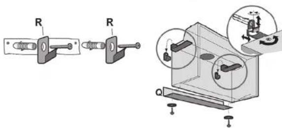
text_image
Technical diagram showing mechanical assembly with labeled components R and Q, including a magnified view of a component with internal mechanisms.3 Installation

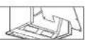
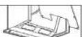
3.4 Fitting the panel door
Open the door, push the brackets in and remove the door. 1.
Place the panel door with the back up on a flat surface.2.
Put the drilling jig (N3) on the back of the panel door. The arrow of the jig should point 3. upwards.
Drill mounting holes of between (K) 2.5 mm to 6 mm deep.4.
Attach the metal panel with the enclosed 8 screws.5.
Fit the door, including panel, onto the exhaust hood. First the top and then the 6 bottom.
Check whether the door opens and shuts properly.7.

text_image
Ø 2,5mm x 6mm max N3 K 6mm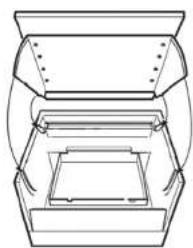
natural_image
Pure technical line drawing of a mechanical component or housing without any text, numbers, or symbols4 Maintenance


Attention! Turn the mains voltage off during cleaning and maintenance by unplugging the plug from the socket or by switching off the circuit-breaker in the meter cupboard.
4.1 Cleaning
The exhaust hood can be cleaned with scapy water and a soft cloth, then rinse with clean water. Do not apply aggressive cleaning agents such as soda. The paintwork on the exhaust hood will remain shiny when it is periodically rubbed with wax.
4.2 Cleaning and replacing the grease filters
Open the lock on the filters and remove the filters.

Attention! Clean the grease filters each month with soapy water. When washed in a dishwasher, the grease filter may discolour slightly. This is normal and does not affect its filtering capacity.


2x
4.3. Changing the carbon filters
The saturation of the filter depends on the intensity of use. The carbon filter needs to be replaced at least every four months.

Attention! The carbon filter cannot be washed for reuse. Saturated carbon is not environmentally friendly, change the filter regularly.
natural_image
Mechanical diagram showing a rotating device inside a housing with a spherical component nearby (no text or symbols)4.4 Removing and fitting the door
Open the door and push the brackets onto the side of the door.
Pull the door out of the conduit. Place the panel door on the exhaust hood again. First the top and then the bottom.
Disposal of appliance and packaging
By ensuring this product is disposed of correctly, you will help prevent potential negative consequences for the environment and human health, which could otherwise be caused by inappropriate waste handling of this product. The local authorities can provide you with the relevant information.
The packaging of this appliance is recyclable. It could have been made from:
cardboard; •
polythene foil (PE); •
CFK-free polystyrene (PS-hard foam).
You need to dispose of these materials responsibly in accordance with official regulations.
To draw attention to the fact that the segregated processing of electric household appliances is compulsory, this appliance carries the symbol of a crossed-out dustbin. This means that at the end of its working life, you may not dispose of the appliance as household refuse. Instead, you should hand it in at a special refuse collection centre run by the local authority or at a dealer's providing this service.
natural_image
Symbol of a trash bin with crossed lines indicating no waste or discharge, no text or numbers present.Segregated processing of household appliances avoids any negative effects on the environment and public health that might otherwise occur.
It enables the recovery of the materials used in the production of this appliance, thus realising considerable savings in terms of raw materials and energy.