156 (2000) - Car ALFA ROMEO - Free user manual and instructions
Find the device manual for free 156 (2000) ALFA ROMEO in PDF.

User questions about 156 (2000) ALFA ROMEO
0 question about this device. Answer the ones you know or ask your own.
Ask a new question about this device
Download the instructions for your Car in PDF format for free! Find your manual 156 (2000) - ALFA ROMEO and take your electronic device back in hand. On this page are published all the documents necessary for the use of your device. 156 (2000) by ALFA ROMEO.
USER MANUAL 156 (2000) ALFA ROMEO
text_image
LA ROME FAOWNER'S MANUAL
ALFA
156

Dear Client,
Thank you for choosing Alfa Romeo.
Your Alfa 156 has been designed to guarantee the safety, comfort and driving pleasure typical of Alfa Romeo.
This booklet will help you to get to know the characteristics and operation of your car.
The following pages contain all the indications necessary for you to be able to maintain the high standards of performance, quality, safety and respect for the environment which characterize this Alfa 156.
The Warranty Booklet also contains the regulations, the warranty certificate and a guide to the services offered by Alfa Romeo.
Services which are essential and precious because, when you purchase an Alfa Romeo you are not only acquiring a car, but the tranquility that comes from knowing that an efficient, willing and widespread organization is at your service for any assistance problems you may have.
Whats more every single component of the Alfa 156 is fully recyclable. At the end of your car's useful lifespan any Alfa Romeo dealer would be pleased to make arrangements for you car to be recycled (in compliance with current regulations in force).
Nature benefits in two ways: there's no pollution from waste disposal, and the demand for raw materials is reduced.
Have a good trip.
This booklet describes all the versions of the Alfa 156, so you should only consider the information concerning the trim level, engine and version purchased by you.
MUST BE READ!
REFUELLING
Petrol engines: only refuel with unleaded petrol with octane rating (RON) no less than 95.
Diesel engines: only refuel with diesel fuel conforming to the European specification EN590.
ENGINE START-UP
Petrol engines with mechanical transmission: make sure the handbrake is pulled; put the gear lever into neutral; press the clutch pedal down to the floor without touching the accelerator, then turn the ignition key to AVV and release it as soon as the engine starts.
Petrol engines with Selespeed transmission or Q-System: keep the brake pedal fully depressed; turn the ignition key to AVV and release it as soon as the engine has started; the transmission sets to neutral automatically (the display shows position N).
Diesel engines: Turn the ignition key to MAR and wait for the 📄 and 📄 warning lights to go off; turn the ignition key to AVV and release it as soon as the engine starts.
PARKING OVER FLAMMABLE MATERIAL

While functioning normally, the catalytic converter reaches high temperatures. For this reason do not park the car over inflammable material, grass, dry leaves, pine needles, etc.: fire hazard.
PROTECTING THE ENVIRONMENT

A system for continuously monitoring emission system components to ensure greater environmental protection is fitted in your car.
ELECTRICAL ACCESSORIES
If, after buying the car, you decide to add electrical accessories (that will gradually drain the battery), contact Alfa Romeo Authorized Services. They can calculate the overall electrical requirement and check that the car's electric system can support the required load.
CODE CARD

Keep the code card in a safe place, not in the car. You should always keep the electronic code written on the CODE card with you in case you need to carry out an emergency start-up procedure.
SCHEDULED SERVICING
Correct maintenance of the car is essential for ensuring it stays in tip-top condition and safeguards its safety features, its environmental friendliness and low running costs for a long time to come.
THE OWNER'S MANUAL CONTAINS...
...information, tips and important warnings regarding the safe, correct driving of your car, and its maintenance. Pay particular attention to the symbols ▲ (personal safety) ↗ (environmental protection) △ (car well-being).
Any queries concerning servicing should be forwarded to the showroom from which the vehicle was purchased, the subsidiary company or to our branch offices or associated companies.
Warranty Booklet
The Warranty Booklet is delivered together with every new vehicle and contains the regulations tied to the services given by Alfa Romeo Services and to the warranty conditions.
Correctly carrying out the scheduled services specified by the manufacturer is the best way to maintain the performance, safety characteristics and low running costs of your vehicle. It is also necessary to maintain warranty cover.
"Service" guide
This contains the Alfa Romeo Authorized Services. The services can be recognized by the presence of the Alfa Romeo badge and logo.
The Alfa Romeo organization in Italy can be found in the telephone book under the letter "A" Alfa Romeo.
Not all the models described in this booklet are available in all countries. Only some of the fittings described in this booklet are fitted as standard to the vehicle. The list of available accessories should be requested from the Alfa Romeo Dealers.
THE SYMBOLS USED IN THIS BOOKLET
The symbols illustrated in these pages show the subjects which should, in particular, be closely studied.

PERSONAL SAFETY
Warning: partially or fully ignoring these rules may lead to serious injury.

PROTECTING THE ENVIRONMENT
This indicates the correct procedures to be followed to prevent the vehicle from damaging the environment.

VEHICLE SAFETY
Warning: partially or fully ignoring these rules may lead to serious damage being caused to the vehicle which, in some circumstances, may cause forfeiture of the warranty cover.
The texts, illustrations and specifications given in this booklet refer to the vehicle at the time of going to press. As part of our ongoing striving to improve our products, Alfa Romeo may introduce technical changes during production, therefore the specifications and fittings may be altered without prior notice. For details on this subject, please apply to the manufacturer's sales network.
GETTING TO KNOW YOUR CAR
SYMBOLS
Special coloured labels have been attached near to or actually on some of the components making up your Alfa 156. These labels bear symbols that remind you of the precautions to be taken as regards that particular component.
ALFA ROMEO CODE SYSTEM
To increase protection against attempted theft, the car is fitted with an electronic engine lock system (Alfa Romeo CODE) which is activated automatically when the ignition key is removed. In fact the grip of each key contains an electronic device which modulates the radio frequency signal transmitted when the engine is started by a special aerial incorporated in the ignition switch. This modulated signal is the "password" by which the control unit recognises the key and only in this condition can the engine be started.
THE KEYS
The car is delivered with two keys, key (A-fig.1) with metal insert and remote control function and another key with metal insert only, without remote control.
The key remote control operates:
— door centralised opening/locking
— opening luggage compartment boot/ tailgate
- activation/deactivation of electronic alarm (if existing)

text_image
A0B0016m Afig. 1
Key metal insert operates:
— the ignition switch
— the driver's door lock and, optional for versions/markets where applicable, the passenger's door lock
— passenger's side Air bag deactivation.
WARNING In order to ensure perfect efficiency of the electronic devices contained inside the keys, they should never be directly exposed to the rays of the sun.
The CODE card (fig. 2) is also supplied with the key and it contains the codes of the keys (both the mechanical one and the electronic one for emergency starting).
The code numbers on the CODE card must be kept in a safe place, not in the car.
The driver should always keep the electronic code given on the CODE card with him in the event of having to carry out emergency starting.

If the car changes owner, the new owner must be given all the keys and the ard.
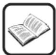
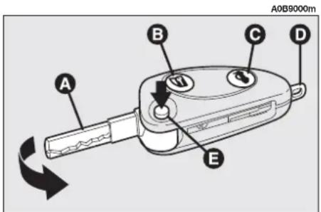
KEY WITH REMOTE CONTROL
The key with remote control (fig. 3) is fitted with:
- a metal insert (A) that can be enclosed in the key grip
- button (B) for remote opening/closing of the doors and turning the electronic alarm on/off (where fitted)
- a button (C) for remote boot unlocking
- removable hook ring (D)
— a button (E) for power-assisted opening of the metal insert.

text_image
A0B0010m Alfa Romer 片 CODE electronic code: 2.3.4.5.6 mechanical code: 7.8.9.0.1fig. 2

text_image
A0B9000m A B C D Efig. 3
The metallic insert (A) of the key operates:
— the ignition switch
— the driver's door lock and, optional for versions/markets where applicable, the passenger's door lock
— passenger's Air bag deactivation.
To move the metallic insert out of the key grip, press button (E).
To insert the metallic insert in the key grip, press the button (E-fig. 3) to release the insert and turn it in the direction of the arrow until it clicks.
To open/close the doors by remote control, press button (B). On cars fitted with electronic alarm system, pressing button (B) also turns the electronic alarm.
WARNING Certain radio devices outside the car (e.g. mobile phones, HAM radio systems) could disturb the remote control frequency. In this case the remote control could malfunction.

WARNING
When button (E) is pressed, take the utmost care to prevent the metal insert from causing injury or damage when it comes out. Button (E) must only be pressed when the key is away from the body, in particular the eyes, and from objects that could be spoilt (e.g. clothes). Never leave the key unattended to prevent anyone, especially children, from holding it and pressing button (E) inadvertently.
OPENING THE BOOT
The boot can be opened by remote control from outside pressing button (C-fig. 3), also when the electronic alarm (where fitted) is on.
In this case the alarm system switches off the boot volumetric protection and control sensor, the system gives two "beeps" (with the exceptions of versions for certain markets) and the direction indicators light up for about three seconds.
Closing the boot again, the control functions are restored, the system gives two "beeps" (with the exceptions of versions for certain markets) and the direction indicators light up for about three seconds.
OPERATION (fig. 4)
Each time the ignition key is turned to STOP position, the Alfa Romeo CODE system deactivates the functions of the engine electronic control unit.
Each time the engine is started, turning the key to the MAR position, the control unit of the Alfa Romeo CODE system sends a recognition code to the engine control unit to deactivate the inhibition of the functions. The recognition code, which is crypted and variable between over 4 billion combinations, is only sent if the system control unit has recognised the code sent to it by the key, which contains an electronic transmitter, through an aerial in the ignition switch.

text_image
A0B0599m 160 200 220 180 240 140 260 120 100 80 60 40 20 888888 888.0 kn/h Bfig. 4
This condition is indicated by a brief flash of the warning light (A) on the check panel.
If the code has not been recognised correctly, the warning light (A) stays on together with the warning light (B).
In this case, you are recommended to return the key to the STOP position and then back to MAR; if the inhibition persists, try again possibly with the other key provided with the car. If it is still impossible to start the car carry out the emergency starting procedure described in section "In an emergency" and turn to an Alfa Romeo Authorized Service.
WARNING Every electronic key has its own code, which must be memorised by the system control unit. To memorise new keys, up to a maximum of eight, apply solely to Alfa Romeo Authorized Services taking with you all the keys in your possession, the CODE card, a personal identity document and the car's possession documents.

The codes of the keys not provided during the new memorising procedure are erased from the memory. This is to ensure that any lost or stolen keys can no longer be used to start the car.
WARNING The Alfa Romeo CODE warning light comes on when travelling with the ignition key on MAR:
1) If the warning lamp lights up while the car is moving, it means that the system is running a self-diagnosis (e.g. due to a voltage drop). The first time you stop you can test the system as follows: switch the engine off by turning the ignition key to STOP; then turn the key back to MAR: the warning lamp will light up and should go out in the space of about one second. If the warning lamp fails to go out, leave the key at STOP for more than 30 seconds and repeat the procedure described previously. If the problem persists, contact your Alfa Romeo Authorized Service.
2) If the warning lamp flashes it means that the car is not protected by the immobiliser. Contact your Alfa Romeo Authorized Service immediately and get them to store the codes of all the keys in the memory.

If after 2 seconds with the key in the MAR position, the warning light turn on again flashing, this means that the code of the keys has not been memorised, thus the car is not protected by the Alfa Romeo CODE system against attempted theft. In this case, contact an Alfa Romeo Authorized Service to have the key codes memorised.
WARNING The system is protected by a 10 A fuse housed in the fuse-holder set under the dashboard (see paragraph "If a fuse or relay blows" in the chapter "In an emergency").
text_image
A0B9000m A B C D Efig. 5
CHANGING THE BATTERY OF THE KEY WITH REMOTE CONTROL
If when pressing button (B or C-fig. 5) the control is rejected or is not performed, the battery should be replaced by a new one of the same type to be found c/o normal retailers. On versions fitted with electronic alarm, the need to replace the remote control battery is indicated by the coming on, with fixed light, of the deterrent led set on the dashboard near the central air vent.

Dead batteries are harmful for the environment. They must be disposed of in special containers as specified by current regulations. Avoid exposure to naked flames and high temperatures. Keep out of reach of children.
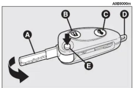
To change the battery (fig. 7):
— move the metal insert (A) to the un-locking position;
— turn the pin (B), taking the reference mark (dot) of the cut to the UNLOCK position (2);
— working on the notch (C) remove the battery holder (D);
— change the battery (E) putting it in the position shown on the holder;
— insert the holder back in the key and lock it, turning the reference mark of the pin (B) to the LOCK position (1).
text_image
A0B0047m E + A B LOCK (1) C UNLOCK (2) Dfig. 7
ELECTRONIC ALARM
(optional for versions/markets where applicable)
DESCRIPTION
The system comprises: transmitter, receiver, control unit with siren and volumetric sensors and anti-lift sensor. The electronic alarm is controlled by a receiver inside the car and it is turned on and off through the remote control incorporated in the key which sends the crypted and variable code. The electronic alarm monitors: unlawful opening of the doors, bonnet and boot (perimetral protection), operation of the ignition key, battery and emergency key cable cutting, the presence of moving bodies (volumetric protection), any abnormal raising/sloping of the car (for versions/markets where applicable) and operates the central door locking system. It also makes it possible to cut off the volumetric protection.
WARNING The engine inhibitor function is guaranteed by the Alfa Romeo CODE system which is activated automatically when the ignition key is removed.
REMOTE CONTROL (fig. 8)
The remote control is built into the key and it is fitted with a button for activating the alarm (B-fig.8)

text_image
A0B9000m A B C D Efig. 8
REQUEST FOR ADDITIONAL KEYS WITH REMOTE CONTROL
The receiver can recognise up to 5 keys with remote control. If during the life of the car a new key with remote control is needed for any reason whatsoever, contact Alfa Romeo Authorized Services directly, taking with you the CODE card, a personal identity document and the car's possession documents.
ACTIVATING THE ALARM
When the doors and boot/bonnet lids are closed and the ignition key is in the STOP or PARK position (key removed), point the remote control towards the car and then press and release the button (B-fig. 8).
With the exception of some markets the system sounds a beep and the door lock is engaged.
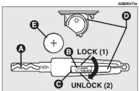
Engagement of the alarm is preceded by a self-diagnosis phase characterised by a change in the frequency at which the deterrent led (A-fig. 9) on the dashboard flashes. If an anomaly is detected the system gives off a further beep.
Surveillance
When the system has been turned on, the led (A-fig. 9) on the dashboard will flash to indicate that the system is in the surveillance mode. The led will flash continuously while the system is under surveillance.
WARNING Operation of the electronic alarm is adapted at the origin to the regulations of the different countries.
text_image
A0B0563m Afig. 9
Self-diagnosis and monitoring of doors and bonnet/boot
If, after the alarm has been activated, a second acoustic signal is heard, check that all the doors and bonnet/boot are closed properly and engage the system once again.
On the other if a door or bonnet/boot lid is not correctly closed it will not be controlled by the system.
If the control signal is repeated when the doors and bonnet/boot are closed properly this means that the self-diagnosis function has detected a system operating fault, in which case it is necessary to contact Alfa Romeo Authorized Services.
DEACTIVATING THE ALARM
To deactivate the alarm, press the button on the key with remote control. The system performs the following (with the exception of some markets):
— the direction indicators turn on twice briefly
— two beeps are sounded briefly by the siren
— the doors are released.
WARNING If the led (A-fig. 9) in the car stays on when the system has been deactivated, (maximum of 2 minutes or until the ignition key is moved to MAR) the following should be borne in mind:
— if the led stays on permanently, it means that the remote control batteries are flat and need replacing;
— if the led continues to flash, but at different intervals than normal, it means that attempts to steal the car have been made, counting the number of flashes it is also possible to identify the type of attempt:
1 flash: right front door
2 flashes: left front door
3 flashes: right rear door
4 flashes: left rear door
5 flashes: volumetric sensors
6 flashes: bonnet
7 flashes: boot
8 flashes: tampering with car starting cables
9 flashes: tampering with battery or cutting emergency key cables
10 flashes: at least three causes of alarm.
AUTOMATIC ENGAGEMENT OF THE ALARM (optional for versions/markets where applicable)
If the alarm has not been engaged with the remote control it will come on automatically after an established time of 30 seconds from the moment that the ignition key has been turned to the STOP or PARK positions and a door or the boot has been opened and then closed again. This condition is shown by the intermittent illumination of the led in the car and by the signalling described previously.
To deactivate the alarm press the button on the remote control.
The alarm is also automatically engaged when the doors are closed using the key.
When the alarm is engaged automatically the doors are not locked.
WHEN THE ALARM IS TRIGGERED
When the alarm is engaged it will sound when:
— one of the doors, the bonnet or the tailgate is opened;
— the battery is disconnected or the electric cables are cut, or the emergency key cables are cut;
— intrusion into the passenger compartment, e.g. window being broken (volumetric protection);
— attempt to start the engine (key at MAR);
— abnormal car raising/sloping (for versions/markets where applicable).
Depending on the markets, the triggering of the alarm will activate the siren and the hazard warning lights (for about 26 seconds). The methods of operation and the number of cycles may vary depending on the versions/markets.
However a maximum number of cycles is foreseen.
Once the alarm cycle has come to an end, the system will return to its normal monitoring state.
INTERRUPTING THE ALARM
To interrupt the alarm press the button on the remote control or, if the remote control battery is down, get into the car, insert the key into the ignition switch and turn the key to MAR.
WARNING If it is necessary for the vehicle to lie inactive for long periods (over 3 weeks), close the vehicle using the key to deactivate the alarm.
VOLUMETRIC PROTECTION
To guarantee correct operation all the windows and the sunroof, if any, should be closed.
This function can be excluded (for example when leaving animals on-board the car) by performing the following operations in quick succession: when the key is at MAR, move the key to the STOP position and then return the key to MAR and then once again to the STOP position. Remove the ignition key.
The led in the car will come on for about 2 seconds to confirm that the function has been excluded.
To restore volumetric protection move the ignition key to the MAR position and hold it in this position for more than 30 seconds.
If requiring to activate an electric control operated by the ignition key at MAR (e.g. electric windows) with the volumetric protection deactivated, turn the ignition key to MAR, operate the control and return the key to STOP within a maximum time of 30 seconds. This way volumetric protection is not restored.
CUTTING OUT OPERATION OF THE SIREN
(for versions/markets where applicable)
When requiring to dispense with the siren acoustic signalling in the alarm condition, simply keep the remote control button (B-fig. 10) pressed for 4 seconds when engaging the system.
This condition is shown by a series of 5 beeps in quick succession after the normal acoustic/visual signals when the system is operated.
The next time the system is activated, normal operation of the siren is restored automatically.

text_image
A0B9000m A B C D Efig. 10
MINISTERIAL HOMOLOGATION
In keeping with the laws in force in each country on the subject of radio frequency, we point out that:
— the separate homologation numbers for each market are given on the last pages of this handbook before the alphabetical index (for some countries also homologation document);
— for markets in which the transmitter needs to be marked with the homologation number, this has been stated on the component.
(Depending on the versions/markets, the code may also be marked on the transmitter and/or on the receiver).
REMOTE CONTROL DOOR LOCKING SYSTEM
The system comprises a receiver inside the car and a transmitter (remote control) incorporated in the key (E-fig. 11).
To lock/unlock the locks, point the transmitter towards the car, press and release the button (B-fig. 11).
WARNING Should it be necessary to programme additional remote controls, contact Alfa Romeo Authorized Services.
text_image
A0B9000m A B C D Efig. 10
IGNITION DEVICE
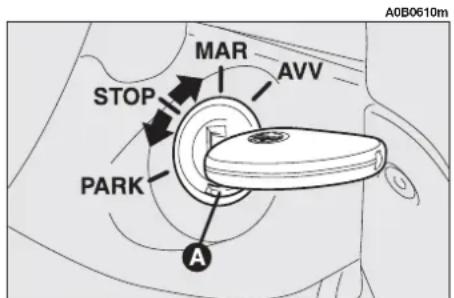
THE SWITCH (fig. 12)
The key can be moved to one of four positions:
— STOP: engine switched off, key can be removed, engine lock engaged, steering lock engaged, all services excluded apart from those powered directly (e.g. hazard warning lights).
— MAR: drive position. The engine lock is deactivated and all electrical devices are powered.
WARNING Never leave the key in this position when the engine is stationary.
text_image
MAR AVV STOP PARK A A0B0610mfig. 12
- AVV: unstable position for starting the engine.
WARNING If the engine does not start, return the ignition key to the STOP position and repeat the sequence.
The ignition block is fitted with a safety device preventing it from being moved to the AVV position when the engine is already running.
— PARK: engine switched off, key can be removed, engine lock engaged, steering lock engaged, sidelights automatically switched on.
WARNING To turn the key to the PARK position, button (A) located on the switch should be pressed first.

WARNING
When leaving the car always remove the key from
the ignition to prevent any passenger in the car from inadvertently activating the controls. Never leave children unattended in the car. Remember to engage the handbrake and if the car is facing uphill, first gear and if the car is facing downhill, reverse.

If the ignition device is tampered with (for example during an attempted
break-in) have it checked over by Alfa Romeo Authorized Services, before travelling again.
STEERING LOCK
Engaging lock:
— move the ignition key to the STOP or PARK position and remove the key lightly turning the steering wheel to facilitate the locking action.
Releasing the lock:
— turn the key to the MAR position and gently rock the steering wheel.

WARNING
Never remove the key with the car on the move.
The steering wheel would lock automatically the first time the steering wheel is turned. This also occurs if the car is towed.

WARNING
It is absolutely forbidden to carry out whatever aftermarket operation involving steering system or steering column modifications (e.g.: installation of anti-theft Device) that could badly affect performance and safety, cause the lapse of warranty and also result in non-compliance of the car with homologation requirements.
DOORS

WARNING
Before opening a door, en- sure that this can be done
safely.
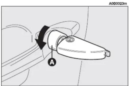
OPENING/CLOSING FROM OUTSIDE
Front doors
— To open the driver's door turn the key clockwise and to open the passengers' door, optional for versions/markets where applicable, turn the key anti-clockwise, then remove the key and press the button (A-fig. 13).
text_image
A0B0023m Afig. 13
— To close the door, turn the key in the opposite direction.
Rear doors
— To open the door, only with the inner knob (A-fig. 14) raised, pull the opening handle (A-fig. 15).
— To close, press the button (A-fig. 14) also with the door open, then close the door.

text_image
A A0B0369mfig. 14
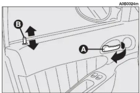
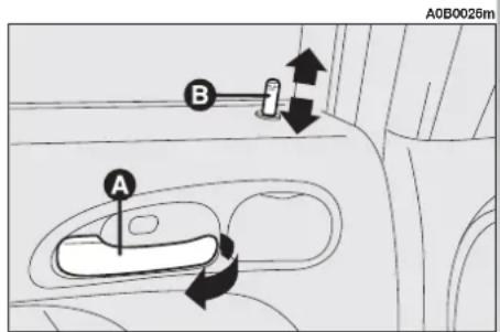
OPENING/CLOSING FROM INSIDE
Front doors
— To open the door pull the handle (A-fig. 16) regardless of the position of knob (B).
— To close the door pull the flap. To prevent the door from being opened from outside press knob (B).
Rear doors

WARNING
The rear doors can only be opened if the child safety s been released.
- To open the door pull handle (A-fig. 17).
— To close the door press the knob (B) even when the flap is open, and then close the flap.
If the boot is not properly shut, the warning light will come on on the instrument panel or (where applicable) on the Info-center display (together with relevant message).
CENTRALIZED LOCKING
This permits centralized locking of all doors, both front and rear.
To operate the centralized locking device the doors must be perfectly closed otherwise the system will not work.
For versions/markets, where applicable, central locking depends on the complete closing of all the doors and of the boot.
— From outside: when the doors are closed, insert and turn the key in the lock of one of the two front doors.
— From inside: when the doors are closed, press one of the knobs (B-fig. 16) located on the front doors, engage/release the centralized locking system.

text_image
A0B0025m Afig. 15
text_image
A0B0024m A Bfig. 16
text_image
A0B0026m A Bfig. 17
By pressing the knob (B-fig. 17) on one of the rear doors only that particular door will be locked.
WARNING For the front doors it is not possible to keep the knob (B-fig. 16) down if the door has not been shut properly.
WARNING The centralized locking system can be deactivated, thus unlocking all doors, by lifting the door opening lever on one of the two front doors.
If the power supply is interrupted (burnt fuse, battery disconnected, etc.) each door can be opened manually from both inside and outside the car.
WARNING The intervention of the inertial fuel cut-off switch causes the automatic door unlock and inhibits door locking for about 30 seconds. After this time, door locking control unit operation is restored.
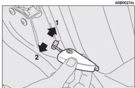
CHILD SAFETY LOCK
The rear doors are equipped with a special device (fig. 18) which prevents the door being opened from inside.
WARNING Each device only acts on the door on which it is installed.
The device can only be engaged with the doors open, raising or lowering the control with the ignition key:
position 1 (control up) — device engaged (door locked);
position 2 (control down) — device released (door can be opened from inside).

WARNING
Always use this device when carrying children.

WARNING
After activating the safety device check that it is g correctly by pulling on the ever used to open the door.
text_image
A0B0027m 1 2fig. 18
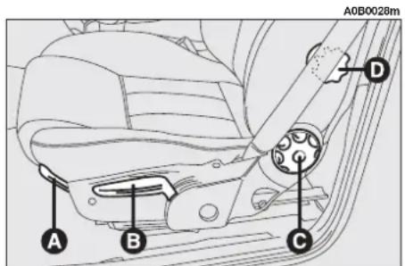
FRONT SEATS

WARNING
Adjustments may be made solely with the car sta-
tionary.
Fig. 19: standard equipment;
Fig. 20: sporty seats (where applicable);
Fig. 21: sporty seats and lateral air bags.
MOVING THE SEATS BACKWARDS OR FORWARDS
Lift lever (A) and push the seat backwards or forwards: in the driving position the arms should be slightly flexed and hands should rest on the rim of the steering wheel.

WARNING
Once you have let go off the lever, check that the seat is firmly locked in the runners by trying to move it back and forth. If the seat is not locked properly, in the case of collision t might move unexpectedly with clearly dangerous consequences.
text_image
A0B0028m A B C Dfig. 19

text_image
A0B0054m A B E Cfig. 20
ADJUSTING THE HEIGHT OF THE DRIVER'S SEAT
To raise the seat, pull the lever (B) taking it upwards, then continue operating the lever (up and down) until reaching the required height, then release the lever. To lower the seat, push the lever (B) downwards, then operate the lever (up and down) until reaching the height required.
WARNING Adjustment must only be carried out when seated in the driver's seat.
ADJUSTING THE ANGLE OF THE BACKREST
This can be done by turning the knob (C) until the desired position is reached.
The sporty seats equipped with lateral air bags have an electric adjustment; use the button (D-fig. 21) on the outer part of the seat to set the seat back in the required position.
BACKREST ANGLE ELECTRIC ADJUSTMENT (optional for versions/markets where applicable)
This can be done by pressing button (D) located on the outer part of the seat.

text_image
A0B0053m A B D E F Bfig. 21
LUMBAR ADJUSTMENT OF THE DRIVER'S SEAT (optional for versions/markets where applicable)
Adjustment is done by turning the knob (E) until reaching the most comfortable position.
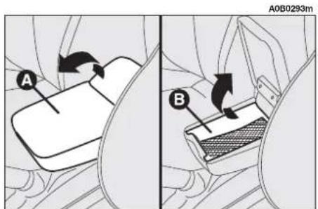
CENTRE ARMREST (where required)
To use the armrest lower it as illustrated.
Inside the armrest there is an oddment compartment (B-fig. 22); to use it, raise the cover (A).
text_image
A B A0B0293mfig. 22
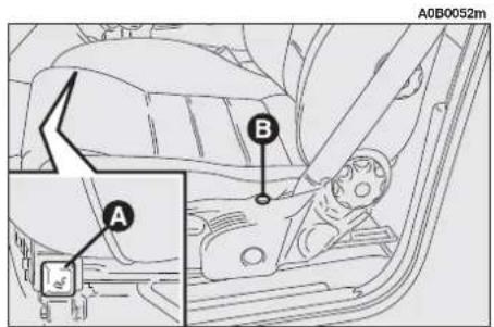
SEAT WARMING (fig. 23) (optional for versions/markets owhere applicable)
The seat warming pad can be switched on and off using switch (A) on the inner side of the seat; for sporty seats, press the switch (F-fig. 21) on the outer side of the seat.
When the warming pad is on, the warning light (B) on the outer side of the seat turns on.
text_image
A0B0052m A Bfig. 23
ADJUSTING THE HEADRESTS (fig. 24)
To increase the safety of passengers, the headrests are adjustable in height and, for versions with Recaro seats they are also adjustable in rake.
To adjust the height: move the headrest up or down, then release it and make sure that it is locked in one of the pre-established positions.
For angle adjustment (where applicable): take hold of the headrest and turn it to the most suitable position.
WARNING The shape of the headrest may vary depending on the version and/or market. The example shown is used only to demonstrate the methods by which it can be adjusted.

WARNING
Remember that the head restraints must be positioned so that they are supporting the back of the head and not the neck. They will only be able to provide effective protection in the event of a collision if they are in this position.
REAR POCKETS (where required) (fig. 25)
The front seats are provided with a pocket in the rear of the seat back.
REAR SEAT
CENTRE ARMREST (fig. 26) (where required)
To use the centre armrest, lower it holding the grip (A) as illustrated.
A0B0564m
text_image
Diagram showing a car seatbelt with labeled component A, likely illustrating vehicle safety or safety instructions.fig. 26

natural_image
Diagram of a car interior showing a seatbelt mechanism with directional arrows indicating motion (no text or symbols)fig. 24

natural_image
Technical line drawing of a mechanical component with a curved panel and circular features (no text or symbols)fig. 25
text_image
A0B0565m Afig. 27
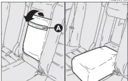
SKI COMPARTMENT (optional for versions/markets where applicable)
The compartment may be used for carrying long loads.
natural_image
Interior view of a car seat with a laptop and directional arrow indicating rotation (no text or symbols)fig. 28
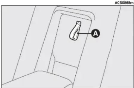
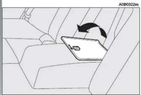
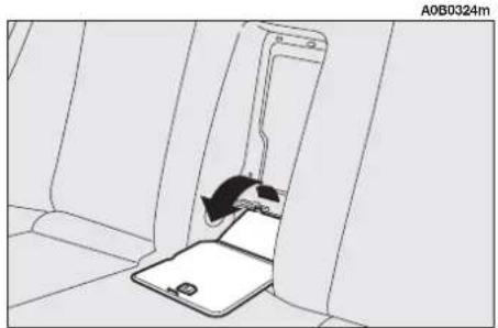
To gain access to this compartment, lower the armrest, pull the grip (A-fig. 27) of the lid and lower it onto the armrest (fig. 28).
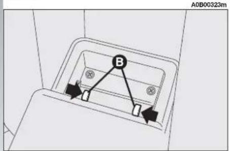
The compartment can be extended by removing the armrest: with the armrest lowered, press the two small handles (B-fig. 29) at the base of the armrest inwards and remove it. Then pull the grip of the lid and lower it onto the rear seat (fig. 30).
text_image
A0B00323m Bfig. 29
natural_image
Interior view of a vehicle seatbelt with a small car slot inserted into the seat (no text or symbols visible)fig. 30
HEADREST
The car is fitted with two headrests for the side seats. On request, for versions/markets where applicable, a third headrest is available for the centre seat.
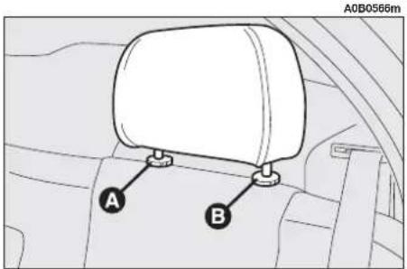
If necessary the headrests can be removed as follows:
— raise the headrest to the maximum height (where required);
- press both buttons (A and B-fig. 31) and remove the headrests.
text_image
A0B0566m A Bfig. 31
STEERING WHEEL ADJUSTMENT
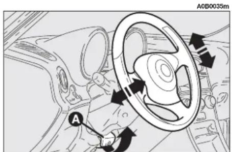
The steering wheel position is adjustable and may be move nearer to or further away from the driver and also raised or lowered.
To do this, it is necessary to release lever (A-fig. 32) and pull it towards the steering wheel.
After setting the steering wheel in the most appropriate position, lock it pushing the lever fully home.

WARNING
The steering wheel position must only be adjusted with
the car stationary.

WARNING
It is absolutely forbidden to carry out whatever after-
market operation involving steering system or steering column modifications (e.g.: installation of anti-theft Device) that could badly affect performance and safety, cause the lapse of warranty and also result in non-compliance of the car with homologation requirements.
ADJUSTING THE REAR-VIEW MIRRORS
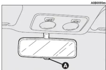
INTERNAL REAR-VIEW MIRROR
The mirror, fitted with a safety device which releases it in the event of a violent impact can be moved to two positions: normal or anti-glare by operating lever (A-fig. 33).
text_image
A0B0035m Afig. 32
text_image
A0B0595m Afig. 33
DOOR MIRRORS
Electrically adjustable (fig. 34)
Select the mirror to be adjusted (right or left) using switch (A):
— move switch (A) to (B) to adjust the left door mirror;
— move switch (A) to (D) to adjust the right door mirror.
Then, reposition the switch (A) in the intermediate locking position (C).
WARNING The mirror can only be adjusted electrically when the ignition key is in the MAR position.
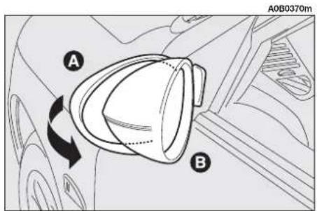
Folding (fig. 35)
— If necessary (for example when the size of the mirror causes difficulty in narrow spaces) the door mirror can be folded in towards the car from position (A) to position (B).

WARNING
When travelling the door mirrors must always be in (A).

WARNING
As the driver's door mirror is curved, it may slightly alter the perception of distance.
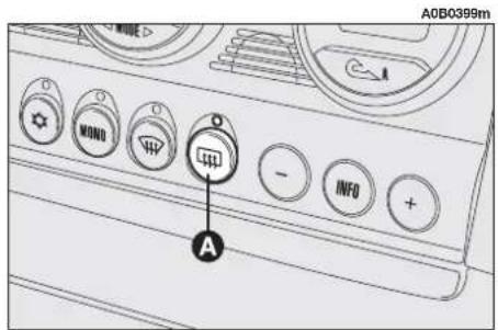
Defrosting/demisting (fig. 36)
The electric mirrors can be fitted with heating coils which are operated together with rearscreen heating pressing button (A) and prevent the mirrors from frosting and/or misting.
WARNING This function is timed and is deactivated after a few minutes.

text_image
A0B0018m A B C Dfig. 34
text_image
A B A0B0370mfig. 35
text_image
ADB0399m MONO A INFO +fig. 36
POWER WINDOWS
FRONT
WARNING With ignition key at STOP windows can be opened manually for about max. 2 minutes or until opening one of the front doors.
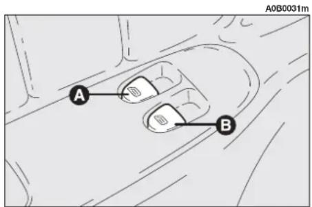
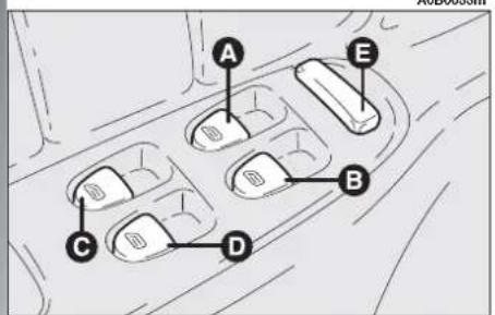
Driver's (fig. 37-39)
The driver's door panel plate contains the buttons which, with the ignition key at MAR, operate the following windows:
A — left front window
B — right front window
C — left rear window (where fitted)
D — right rear window (where fitted)
E — rear door window control inhibitor (where fitted) (with the inhibitor activated the button is up, press again to re-enable the rear buttons).
WARNING The driver's power window is fitted with a "continuous automatic operation" for both lowering and raising the window device. A brief press on the upper or lower part of the button will cause the window to move and continue its stroke automatically: the window stops in the position required by pressing either the upper or lower part of the button again.
Passenger's (fig. 38)
Button (A) is used to operate the passenger's window.
WARNING The passenger's window is fitted with a device for "continuous automatic operation" only for lowering it. The device works as described for the driver's window.
REAR (where required)
The rear windows are operated by the handles on the door panels.
On request for versions/markets where applicable, the rear doors can be fitted with power windows with split controls on driver's door (C and D-fig. 39) and on each rear door (A-fig. 40).
With the ignition key at MAR, press the button to lower the window; pull the button to raise it.
text_image
A0B0031m A Bfig. 37
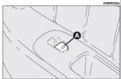
text_image
A0B0032m Afig. 38

WARNING
Incorrect use of the power windows can be dangerous.
Before and during operation of them always make sure that the passengers are not exposed to the risk of harm caused either directly by the windows in motion or by personal objects drawn or knocked by them.

WARNING
When leaving the car always remove the ignition
key to prevent passengers (especially children) from being injured by the power windows inadvertently operated.

Do not hold the button down when the window is fully open or fully closed.
Versions not fitted with power windows have a window winder (A-fig. 40a) for working the window by hand.
text_image
A E B C Dfig. 39
A0B0034m
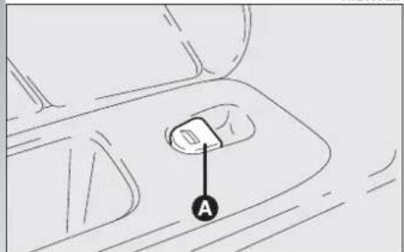
text_image
Afig. 40

text_image
A AaBub00mfig. 40a
SEAT BELTS
USING THE SEAT BELTS
The belt should be worn keeping the chest straight and rested against the seat back.
Take hold the tongue (A-fig. 41) and insert it into the buckle (B), until hearing the locking click.
At removal, if it jams, let it rewind for a short stretch, then pull it out again without jerking.
To unfasten the seat belts, press button (C). Guide the seat belt with your hand while it is rewinding, to prevent it from twisting.

text_image
A0B0325m A B Cfig. 41

WARNING
Never press button (C) when travelling.
Through the reel, the belt automatically adapts to the body of the passenger wearing it, allowing freedom of movement.
When the car is parked on a steep slope the reel mechanism may block; this is normal. The reel mechanism prevents the webbing coming out when it is jerked or if the car brakes sharply, in a collision or when cornering at high speed.
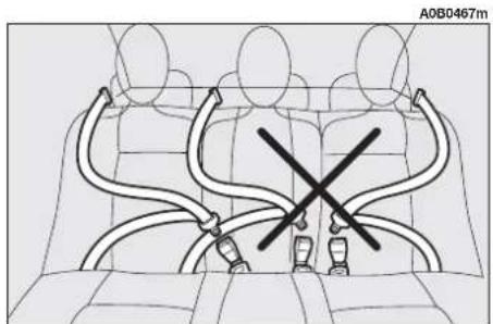
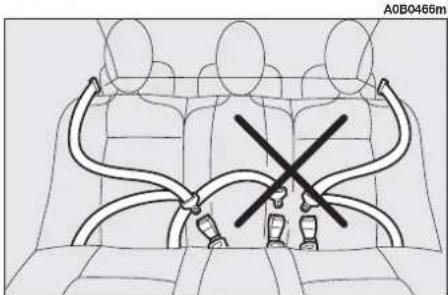
The centre seat is fitted with inertial seat belt with three anchor points and reel like side seats (fig. 42).
On request, for versions/markets where applicable, the rear seat can be fitted with inertial seat belt with three anchor points and reel for side seats and lap belt with two anchor points for the centre seat (fig. 44).
In order to ensure that the correct tabs, are fitted in the correct clips, the tabs of the side belts and the clip of the central belt (only abdominal) are incompatible (fig. 43).

WARNING
To offer the highest level of protection, the rear seat
belts should be fastened as shown in fig. 42 and fig. 44.

natural_image
Line drawing of a car interior with three seated cars and two curved arms, no text or symbols presentfig. 42
natural_image
Diagram of a car seatbelt system with no visible text or symbolsfig. 43

natural_image
Diagram of car seatbelt harnesses arranged in a backseat (no text or symbols)fig. 44
text_image
A0B0466mfig. 45

WARNING
Proper backrest coupling is guaranteed when button
(A-fig. 46) set near each handle (B) is retracted in the handle.

WARNING
Make sure the seat back is correctly hooked on both
sides (not visible red buttons (A) to prevent seat back being thrown forwards and injuring passengers should you brake sharply.

WARNING
Remember that, in the event of an accident, any
passengers occupying the rear seats who are not wearing a seat belt not only subject themselves to great personal risk but constitute a danger to the occupants of the front seats.

WARNING
After tilting, when resetting the rear seat in straight po-
sition, take care to reposition the seat belt properly to have it ready for use.
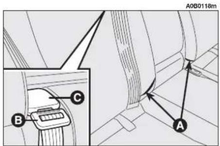
When the rear seats are not occupied, use the proper pockets (A-fig. 47) on the backrest to stow the seat belt clips neatly, the tab (B) of the central abdominal belt shall be fitted into (C) (see next paragraph "Rear abdominal centre housing").
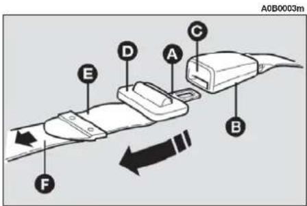
REAR CENTRAL ABDOMINAL BELT (fig. 48)
Fasten the belt by inserting the tab (A) into the clip (B), until a click is heard.
To adjust the belt, run the tape in the buckle (D) pulling the end (E) to tighten and part (F) to loosen.
Press button (C) to release the belt.
WARNING The belt is adjusted properly when it fits closely across the hips.

text_image
A B A0B0123mfig. 46
text_image
A0B0118m A B Cfig. 47
text_image
A0B0003m A B C D E Ffig. 48
REAR ABDOMINAL CENTRE BELT HOUSING (fig. 49)
When the rear centre belt, which is of the abdominal type, is not in use, hook the tongue (A) in the special support (B) on the rear seat back.

WARNING
Always hook the belt tip when it is not used to pre-
vent it from hitting the occupants in the event of a crash.
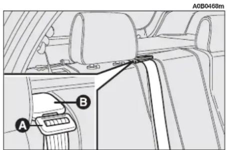
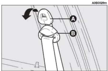
ADJUSTING THE HEIGHT OF FRONT AND REAR SIDE SEAT BELTS
(Sportwagon versions only)
The rocker ring of the rear side belts has three different positions through which belt height adjustment is possible.
Always adjust the height of belts adapting them to the size of the person wearing them. This precaution will improve their effectiveness, substantially reducing the risk of injury in the event of a crash.
Correct adjustment is obtained when the belt passes about half way between the end of the shoulder and the neck.
To adjust the seat belt, raise or lower the anchoring device grip (A-fig. 50) of the front (A-fig. 51) or side rear seat belts (Sportwagon versions only), and move at the same time the ring (B) to the most suitable of the set positions.
text_image
A0B0468m A Bfig. 49
text_image
A0B0029m A Bfig. 50

text_image
A0B0099m A Bfig. 51

WARNING
After adjustment, always check that the slider (B) is anchored in one of the positions provided. To do this, with the button (A-fig. 50) or (A-fig. 51) released, exert a further pressure to allow the anchor device to catch if release did not take place at one of the preset positions.

WARNING
Make the height adjustment when the car is stationary.
PRE-TENSIONING DEVICES
To increase the efficiency of the front seat belts, Alfa 156 is fitted with pre-tensioning devices.
These devices “feel” that the car is being subject to a violent impact by way of a sensor rewind the seat belts a few centimetres. In this way they ensure that the seat belt adheres to the wearer before the restraining action begins.
The seat belt locks to indicate that the device has intervened; the seat belt cannot be drawn back up even when guiding it manually.
WARNING The pretensioner will give maximum protection when the seat belt adheres snugly to wearer's chest and hips.
Front seat pretensioners activate only if front seat belts are properly fitted into buckles. A small amount of smoke may be produced. This smoke is in no way toxic and presents no fire hazard.
The emergency tensioning retractor needs no maintenance or lubrication. Any modification to its original features will nullify the retractor's effectiveness. If, due to unusual natural events (floods, high waves, etc.), the device has been affected by water and mud, it must be replaced.

WARNING
The pretensioner can only be used once. After a col-
lision that has triggered it, have it replaced at Alfa Romeo Authorized Service. The validity of the device is written on the plate located on the front left door near the lock. Contact Alfa Romeo Authorized Services to have pretensioner replaced as this date approaches.

Operations involving banging, vibrations or heating (above 100°C for
a maximum of 6 hours) in the area of the pretensioners may damage or trigger off the device. Vibrations from rough road surfaces or accidental jolting caused by mounting pavements etc. do not have any effect on the pretensioner. If, however, you need assistance, go to Alfa Romeo Authorized Services.

WARNING
Never disassemble or tamper with the pretensioner components. All interventions must be carried out by qualified and authorised personnel. Always contact Alfa Romeo Authorized Services.
GENERAL INSTRUCTIONS FOR THE USE OF THE SEAT BELTS
All the occupants of the car are obliged to respect the local traffic laws regarding the wearing of seat belts.
Always fasten the seat belts before starting.

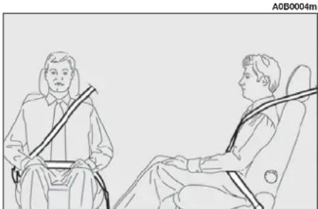
WARNING
The seat belt must not be twisted and should cling tightly to the body. The upper part must pass over the shoulder and diagonally across the chest. The lower part must rest across the pelvis and not across the stomach to eliminate the risk of sliding forwards (fig. 52). Do not use devices (clips, stoppers, etc.) which keep the belts away from the body.

WARNING
Under no circumstances should the components of the seat belts and pretensioner be tampered with or removed. Any operation should be carried out by qualified and authorised personnel. Always contact an Alfa Romeo Authorized Service.

WARNING
To ensure the highest degree of protection, you are recommended to keep the seat backrest in the straightest position possible, and the belt adhering well to the chest and pelvis.
Seat belt should always be worn in both the front and rear positions! Travelling without seat belt increases the risk of serious injury or death in the case of accident.
natural_image
Line drawing of two individuals seated in a chair, one holding a string instrument (no text or symbols)fig. 52

WARNING
If the seat belt has been subjected to shock, for ex-
ample during an accident, it must be completely replaced together with the attachments and their screws, and the pretensioning devices, even if visible defects are not detected as the belt may have lost its resilience.

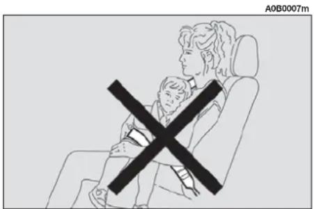
WARNING
Do not carry children on your knee using a single lt for both (fig. 53). Do not other objects to the body.
Seat belts are also to be worn by expectant mothers: the risk of injury in the case of accident is greatly reduced for them and the unborn child if they are wearing a seat belt.
Pregnant women must of course position the lower part of the belt very low down so that it passes under the abdomen (fig. 54).
text_image
A0B0007mfig. 53
HOW TO KEEP THE SEAT BELTS ALWAYS IN EFFICIENT CONDITIONS
— Always use the belts with the tape well taut and never twisted; make sure that it is free to run without impediments.
— After a serious accident, replace the belt being worn at that time, even if it does not appear damaged. Always replace the seat belts if pretensioners have been activated.
— To clean the belts, wash by hand with neutral soap, rinse and leave to dry in the shade. Never use strong detergents, bleach or dyes or any other chemical substance that might weaken the fibres.
— Prevent the reels from getting wet: correct operation of them is only guaranteed if water does not get inside.
— Replace the seat belt if it shows significant wear or cut signs.

natural_image
Line drawing of a person seated in two car seats, one holding a seatbelt, no text or symbols presentfig. 54
CARRYING CHILDREN SAFELY


WARNING
SERIOUS DANGER: Never place cradle child's seats on the front passenger seats of cars equipped with passenger air bag since the air bag activation could cause serious injuries, even mortal. You are advised to carry children always on the rear seat, as this is the most protected position in the case of a crash. In any case, child's seats must absolutely not be positioned on the front seat of car's with passenger's air bag, which during inflation could cause serious injury, even mortal, regardless of the seriousness of the crash that triggered it. Children may placed on the front seat of cars fitted with passenger's air bag deactivation. In this case, it is absolutely necessary to check the warning light ☐ on the check panel to make sure that deactivation has actually took place (see paragraph "Front and side air bags" at item "Front passenger air bag"). The front passenger seat shall be adjusted in the most backward position to prevent any contact between the child's seat and the dashboard.
For the best level of protection in the event of a crash, all occupants must travel seated and secured by suitable restraint systems.
This is even more important for children.
According to 2003/20/EC Directive, this prescription is compulsory for all European Community countries.
Compared with adults, a child's head is proportionately larger and heavier than the rest of the body, while muscles and bone structure are not completely developed. Therefore, in order to restraint them correctly in the event of a crash, different systems are needed then adult seat belts.

fig. 55
A0B0001m
The results of research on the best protection for a child are summarised in European Standard ECE-R44, which in addition to making them compulsory, subdivides restraint systems into five groups:
Group 0 0-10 kg in weight
Group 0+ 0-13 kg in weight
Group 1 9-18 kg in weight
Group 2 15-25 kg in weight
Group 3 22-36 kg in weight
As it may be noted, the groups partially overlap and in fact, in commerce it is possible to find devices that cover more than one weight group (fig. 56).
All the restraint devices must bear the homologation data, together with the control brand, on a solidly fixed label which must absolutely not be removed.
Over 1.50 m in height, from the point of view of restraint systems, children are considered as adults and wear belts normally.
The Lineaccessori Alfa Romeo includes seats for each weight group, which are the recommended choice because they have been designed and specifically experimented for Alfa Romeo cars.
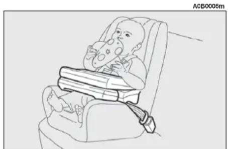
GROUP 0 and 0+
Babies up to 13 kg must be carried facing behind (fig. 56) on a cradle seat, which, supporting the head, does not induce strain on the neck in the event of sharp deceleration.
The cradle is restrained by the car safety belts, as illustrated, and it should in turn restrain the child with the belts incorporated on it.

WARNING
Illustrations is indicative only for assembly. As-
semble the seat according to the compulsory instructions provided with it.
GROUP 1
Starting from 9 kg to 18 kg in weight, children may be carried facing forwards with seats fitted with front cushion (fig. 57), through which the car seat belt restrains both child and seat.

WARNING
Illustrations is indicative only for assembly. As-
semble the seat according to the compulsory instructions provided with it.

natural_image
Line drawing of a baby in a baby car seat with a horizontal bar, no text or symbols presentfig. 56
natural_image
Line drawing of a baby wearing a seatbelt, no text or symbols presentfig. 57

WARNING
Seats exist which are suitable for covering weight groups 0 and 1 with a rear connection to the car belts and its own belts to restrain the child. Because of their mass, they can be dangerous if installed incorrectly fastened to the car belts with a cushion. Strictly adhere to the assembly instructions provided.
GROUP 2
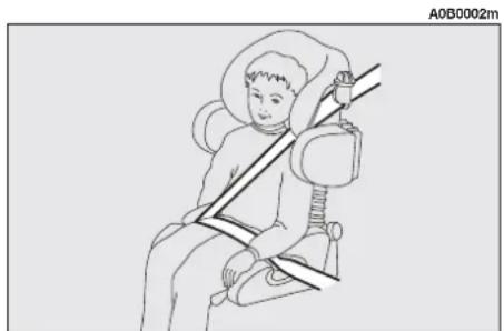
Starting from 15 to 25 kg in weight, children may be restrained directly by the car seat belts. Child seats only have the function of positioning the child correctly in relation to the belts, so that the diagonal part adheres to the chest and never to the neck and that the horizontal part adheres to the child's pelvis and not to the abdomen (fig. 58).
GROUP 3
For children from 22 kg up to 36 kg the child's chest is thick enough not to need the spacer back rest any more.
Fig. 59 shows proper child seat positioning on the rear seat.
Over 1.50 m tall children may wear seat belts like adults.

WARNING
Illustrations is indicative only for assembly. As the seat according to the story instructions provided

WARNING
Illustrations is indicative only for assembly. Assemble the seat according to the compulsory instructions provided with it.
natural_image
Illustration of a person seated in a chair using a seatbelt device (no text or symbols)fig. 58

natural_image
Line drawing of a person sitting on a chair wearing a seatbelt and boots (no text or symbols)fig. 59
PASSENGER SEAT COMPLIANCE WITH REGULATIONS ON CHILD'S SEAT USE
Alfa 156 complies with the new EC Directive 2000/3 regulating child's seat assembling on the different car seats according to the following table:
Front and rear seat (saloon and Sportwagon versions)
Group Range of weight SEAT
| Front passenger Rear side passenger Rear centre passenger seat Seat (inertial seat belt Seat (centre lap belt with three anchor points) with two anchor points) | |||||
| Group 0, 0+ | until to 13 kg | L | U | U | (*) |
| Group 1 | 9 -18 kg | L | U | U | (*) |
| Group 2 | 15 - 25 kg | L | U | U | (*) |
| Group 3 | 22 - 36 kg | L | U | U | (*) |
Key:
U = suitable for child restraint systems of the "Universal" category, according to European Standard ECE-R44 for the specified "Groups"
L = suitable for certain child's restraint systems available at Lineaccessori Alfa Romeo for the specified group
(*) = child's seats cannot be installed on the rear centre seat with lap belt with two anchor points
Below is a summary of the safety rules to be observed when carrying children:
1) The recommended position for installing a child's seat is on the rear seat, as it is the most protected in the event of a crash.

WARNING
If a passenger's air bag is installed, children should never travel on the front seat.
2) If the passenger's air bag is deactivated always check that deactivation has taken place through the special warning light ✕.
3) Carefully follow the instructions provided with the child's seat, which the supplier is obliged to attach. Keep them in the car together with the documents and this booklet. Do not use used seats without the instructions for use.
4) Always pull the tape to check that the belts are buckled.
5) All restraint systems are strictly for one child only: never use for two children at the same time.
6) Always make sure that the belts do not rest on the child's neck.
7) During the journey, do not allow the child to stay in abnormal positions or release the belts.
8) Do not carry children in your arms, not even small babies. No-one, however strong, can keep hold of them in a crash.
9) In the case of accidents, replace the child's seat with a new one.
PRESETTING FOR INSTALLING THE "ISOFIX TYPE" CHILD RESTRAINT SYSTEM
The car is created preset for mounting the Isofix type child restraint system. Isofix is a new European standardised system for carrying children. Isofix type child restraint system is an additional option that does not prevent from using traditional child restraint systems. Isofix type child restraint system covers three weight groups: 0, 0+ and 1.
Due to its different anchoring system, the Isofix type child's seat should be anchored using only the proper brackets provided for the purpose in the car.
It is possible to mount both the traditional restraint system and the Isofix type one, one on the left and the other on the right, for example.
Since sizes are different, it is possible to install max two Isofix type child's seats using the proper couplings on the rear seat or three traditional child's seats using the seat belts. On the front passenger seat it is possible to mount only traditional child's seats.
Lineaccessori Alfa Romeo provides the Kiddy Isofix seat for babies up to 13 kg weight to be positioned facing backwards (groups 0 and 0+) and the seat for babies from 9 to 18 kg weight to be positioned facing the running direction (group 1). The Kiddy Isofix seat has been certified according to the European Standard ECE-R44/03.
Isofix type child's seats are to be anchored to two metal brackets, set between the rear seat back and the cushion and that can be identified through the slots in the seat cover (A-fig. 60).
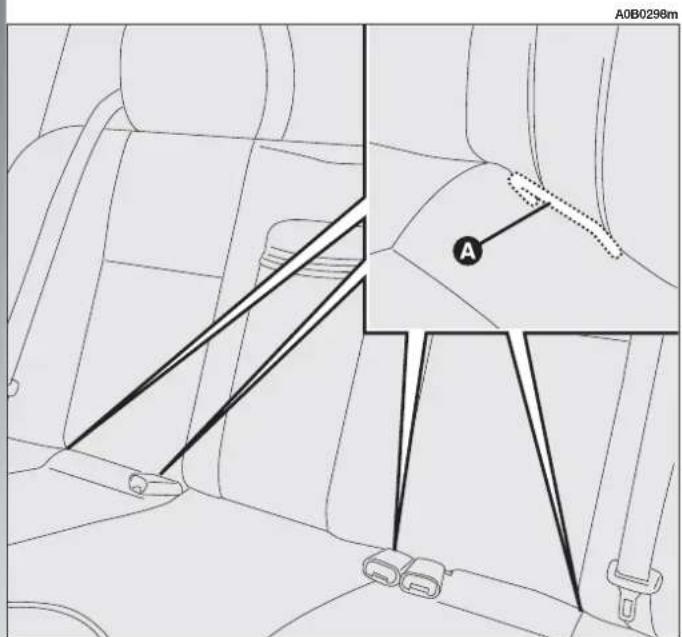
text_image
A0B0298m Afig. 60

WARNING
Install the child restraint system only with the car stationary. The Isofix child restraint system is properly anchored to the preset brackets when clicks are heard. In any case, keep to the installation instructions that must be provided by the child restraint system's Manufacturer.
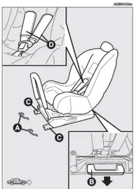
Installation of the seat for the 0 and 0+ groups
For children of the 0, 0+ weight group, the child's seat is facing backwards (babies up to 13 kg) and the child is restrained by the child's seat belts (D-fig. 61).
For proper installation proceed as follows:
- check whether the release lever (B-fig. 61) is at rest position (inward)
— find the presetting brackets (A), then position the child's seat with the fastening devices (C) aligned with the brackets
— push the child restraint system until hearing the locking clicks.
text_image
A0B0400m A B C D A B Cfig. 61
text_image
A0B0401m B C Afig. 62
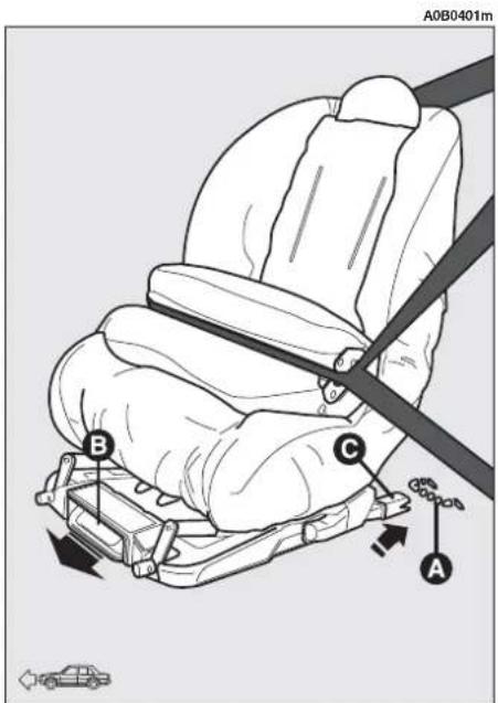
As the child grows up, passing to weight group 1 the child's seat should be mounted facing forwards (running direction).
Installation of the seat for weight group 1
For proper installation proceed as follows:
- check whether the release lever (B-fig. 62) is at rest position (inward);
— find the presetting brackets (A), then position the child's seat with the fastening devices (C) aligned with the brackets;
— push the child restraint system until hearing the locking clicks.
If the Isofix type seat is positioned facing backwards, the passenger's seat must be positioned completely back until touching the child's seat back.
FRONT AND SIDE AIR BAGS
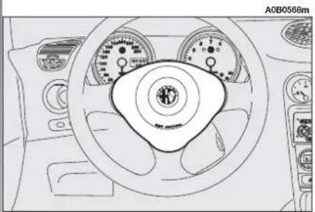
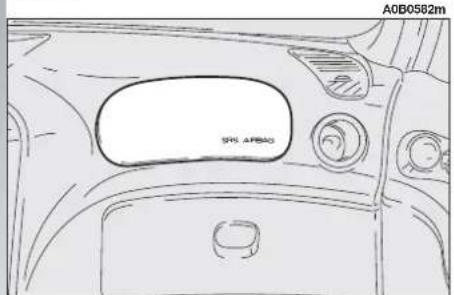
The car is fitted with front Air bags for the driver (fig. 63), for the passenger (fig. 64), side bags (fig. 65) and window bags (fig. 66).
FRONT AIR BAGS
Description and operation
The front air bag (driver's and passenger's) is a safety device that comes into action in the event of a head-on collision.
natural_image
Line drawing of a car dashboard with steering wheel and gauges (no text or symbols)fig. 63

natural_image
Interior view of a car with driver seat and dashboard, showing no visible text or symbolsfig. 65
natural_image
Top-down line drawing of a car dashboard and air vent (no text or symbols)fig. 64

natural_image
Top-down technical sketch of a car interior showing dashboard and steering wheel (no text or symbols)fig. 66
It is formed of an instantly-inflating cushion contained in a special recess:
— in the centre of the steering wheel for the driver;
— in the dashboard and with a larger-sized cushion for the passenger.
The front Air bag (driver's and passenger's) is a device designed to protect the occupants in the event of head-on collision of medium-high severity by the interposition of the cushion between the occupant and the steering wheel or dashboard.
In the event of a crash, the electronic control unit processes the signals leading from a deceleration sensor and when necessary, triggers inflation of the cushion.
The cushion inflates instantly as a protective barrier between the occupants' bodies and the structures which could cause injury. The cushion deflates immediately afterwards.
The front air bag (driver's and passenger's) does not replace but is complementary to the use of belts, which should always be worn, as specified by law in Europe and most non-European countries.
In the event of a crash a person that is not wearing the seat belt moves forwards and may come into contact with the cushion while it is still opening. Under these circumstances the protection offered by the cushion is reduced.
Front air bags are designed to protect car's occupants in front crashes and therefore non-activation in other types of collisions (side collisions, rear-end shunts, roll-overs, etc...) is not a system malfunction.
In collisions against highly deformable or mobile objects (road signposts, heaps of ice or snow, etc.), rear collisions (hit from behind by another vehicle), side collisions, wedging under other vehicles or protective barriers (for example under a lorry or guard rail) cutting in of the air bag is not activated as it does not offer any more protection than the seat belts therefore activation would be inappropriate.
Therefore the failure to be triggered does not mean that the system is not working properly.

WARNING
Please don't apply stickers or other objects to the steering wheel, to the air-bag cover on the passenger's side or on the side roof lining to the upholstery on the roof side. Don't place objects on the dashboard passenger's side (such as mobile phones) because they could tamper with the correct opening of the passenger's air-bag and than cause serious injuries to the vehicle occupants.
PASSENGER'S FRONT AIR BAG
The passenger's front air bag has been designed to improve the protection of a person wearing a seat belt.
Its volume at maximum inflation fills most of the space between the dashboard and the passenger.

WARNING
SERIOUS DANGER: The car is fitted
with front passenger's air bag. Never place cradle child's seats on the front passenger seat of cars equipped with passenger air bag since the air bag activation could cause serious injuries, even mortal. In the case of need, always deactivate the passenger's air bag when a child's seat is placed on the front seat. The front passenger seat shall be adjusted in the most backward position to prevent any contact between child's seat and dashboard. Even if not ruled by law, for better protection of adults you are recommended to reactivate the air bag immediately as soon as child transport is no longer necessary.
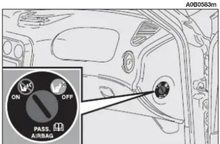
MANUAL DEACTIVATION OF PASSENGER'S FRONT AIR BAG
Should it be absolutely necessary to carry a child on the front seat, the passenger's front air bag can be deactivated.
Deactivation/reactivation takes place with ignition key at STOP and operating it in the special key switch on the right-hand side of the dashboard (fig. 67). Access to the switch is only possible with the door open.

WARNING
Use the switch only with the engine off and the ig-key removed.
The key switch (fig. 67) has two positions:
1) Passenger's front Air bag active: (ON position Ⓧ) warning light on check panel off; it is absolutely prohibited to carry children on the front seat.
2) Passenger's front Air bag deactivated: (OFF position 📋) warning light 📋 on check panel on; it is possible to carry children protected by special restraint systems on the front seat.
The warning light 🖼️ on the check panel glows steadily until the passenger's Air bag is reactivated.
Deactivation of the front passenger's air bag does not prevent operation of the side Air bags.
With the door open the key can be inserted and removed in both positions.
text_image
A0B0583m ON OFF PASS. AIRBAGfig. 67
SIDE AIR BAGS
(SIDE BAG - WINDOW BAG)
The side bag and window bag have the task of increasing protection of the occupants in the event of a side crash of medium-high severity.
They are formed of an instantaneously-inflating cushion:
— the side bag is housed in the back rest of the front seats; with this solution it is always possible to have the cushion in the optimum position in relation to the passenger, regardless of the adjustment of the seat;
— the window bags, which are "curtain" cushions, are housed in the side roof lining covered by a special trim, which makes it possible to extend the cushion downwards. This solution, designed to protect the head, makes it possible to offer the highest degree of protection to the front and rear occupants in the event of side crash, thanks to the wide cushion inflation surface.
In the event of a side crash, an electronic control unit processes the signals leading from a deceleration sensor and activates, when necessary, inflation of the bags.
The bags inflate instantaneously, setting themselves between the body of the front passengers and the car door. The bags deflate immediately afterwards.
In the event of minor side crashes (for which the restraining action of the seat belts is sufficient), the air bags are not deployed. Also in this case it is of vital importance to wear the seat belts since in case of side crash they guarantee proper positioning of the occupant and prevent the occupant to be pitched out of the car in case of violent crashes.
Therefore the side air bags do not replace but are complementary to the use of belts, which you are recommended to always wear, as specified by law in Europe and most non-European countries.
Operation of the side air bags and window bags is not disabled by the front air bag deactivation switch, as described in the previous paragraphs.
WARNING In the event of side crash, you can obtain the best protection by the system keeping a correct position on the seat, thus allowing correct window bag unfolding.

WARNING
Never rest head, arms and elbows on the door, on the windows and in the window bag area to prevent possible injuries during the inflation phase.
WARNING The front and/or side air bags may be activated if the car is subjected to heavy shocks or accidents that involve the underbody area, such as for example violent bumps against steps, pavements or fixed obstacles on the ground, falling into big holes or bumpy roads.
WARNING The triggering of air bags releases a small amount of powder. This powder is not harmful and does not indicate a start of fire; also the surfaces of the deployed bag and the car interior may be covered with dusty residue: this may irritate the skin and eyes. In the event of exposure, wash with neutral soap and water.

WARNING
Never lean head, arms and elbows out of the window.
The airbag system has a validity of 14 years for the pyrotechnic charge and 10 years for the coil contact (see the plate located on the front left door near the lock).
Contact Alfa Romeo Authorized Services for replacement as these dates approach.
WARNING If an accident has triggered the air bag, Alfa Romeo Authorized Services must be contacted to have the devices activated replaced and to have the whole system checked.
All operations involving checking, repairing and replacing components concerning the Air bag must be carried out by Alfa Romeo Authorized Services.
If the car is to be demolished, Alfa Romeo Authorized Services should be contacted beforehand to have the system deactivated.
If the car changes ownership, the new owner must be informed of the instructions for use and of the above warnings and be given this "Owner's Manual".
WARNING The triggering of the pretensioners, front air bags and side bags is decided by the electronic control unit in a differentiated manner depending on the type of crash. The failure to trigger one or more of them does not necessarily indicate a system malfunction.
GENERAL CAUTIONS

WARNING
If the ⚙ warning light does not turn on when turning the ignition key to MAR or if it stays on when travelling, this could indicate a failure in safety retaining systems; under this condition air bags or pretensioners could not trigger in the event of collision or, in a restricted number of cases, they could trigger accidentally. Stop the car and contact Alfa Romeo Authorized Services to have the system checked immediately.

WARNING
Do not cover the back rest of front seats with trims or there are not set for the use bags.

WARNING
Never travel with objects on your lap, in front of the with a pipe, pencil, etc. be-your lips. Serious injury may in the case of the air bag be-gered.

WARNING
Always keep your hands on the steering wheel rim when driving, so that if the Air bag is triggered, it can inflate without meeting any obstacles. Do not drive with the body bent forwards, keep the seat back rest in the erect position and lean your back well against it.

WARNING
If the car has been stolen or an attempt to steal it has been made, if it has been subjected to vandals or floods, have the Air bag system checked by Alfa Romeo Authorized Services.

WARNING
Please don't apply stickers or other objects to the bag wheel, to the air-bag in the passenger's side or on the roof lining to the upholstery in the roof side. Don't place on the dashboard passen-side (such as mobile phones) they could tamper with the opening of the passenger's hand and than cause serious in-to the vehicle occupants.

WARNING
You are reminded that when the ignition key is engaged and in the MAR position, the Air bags can be triggered also on a stationary vehicle, if it is bumped by another moving vehicle. Therefore, even with the car stationary, never allow children on the front seat. You are also reminded that with the car stationary, without the key engaged and turned, the Air bags are not triggered in the event of an impact; in this case the failure to trigger the air bags should not be considered a system failure.

WARNING
Turning the ignition key to MAR the ⏻ warning light
(with the passenger's front Air bag deactivation switch at ON) turns on for about 4 seconds, and then flashes for another 4 seconds to remind that the passenger's Air bag and corresponding side Air bags will be activated in the event of a crash, then it goes off.

WARNING
The front Air bags are de- signed to be triggered for
heavier crashes than the pretensioners. It is therefore normal for the pretensioners only to be triggered for crashes within the two activation thresholds.

WARNING
Do not hook rigid objects to the coat hooks and to the handles.

WARNING
Do not wash the seat back with pressurised water or (by hand or at automatic ashing stations).

WARNING
The air bag does not replace the seat belts, but in their effectiveness. Additionally, as the front air bags are gaged for head-on collision speed, side crashes, crashes behind or overturning, in cases the occupants are pro-only by the seat belts, which therefore, always be fas-
STEERING WHEEL LEVERS
The devices and services controlled by the levers on the steering wheel can only be activated when the ignition key is in the MAR position.
LEFT-HAND LEVER
The left-hand lever controls the external lights except the foglamps and the rear foglight.
When the external lights are switched on the various controls located on the dashboard are illuminated.
The sidelights will come on if the ignition key is in the PARK position, regardless of the position of the knurled ring.
Lights switched off (fig. 68)
When the pointer on the knurled ring is opposite the symbol O, the external lights are switched off.
Sidelights (fig. 69)
The sidelights are switched on by turning the knurled ring from 0 to ⚙.
The ≥0≤ warning light on the instrument panel will come on at the same time.
Dipped-beam headlights (fig. 70)
These are switched on by turning the knurled ring from ⚙ to ⏱.
Main-beam headlights (fig. 71)
When the knurled ring is in the position, the headlights can be changed from dipped-beam to main-beam by pushing the lever towards the dashboard (stable position). The warning light will come on on the instrument panel.
To return from main-beam to dipped-beam, once again pull the lever towards the steering wheel and then release.

text_image
A0B0371m fig. 68
text_image
A0B0372m 图. 69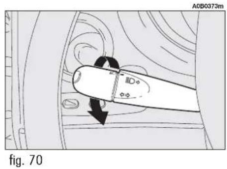
text_image
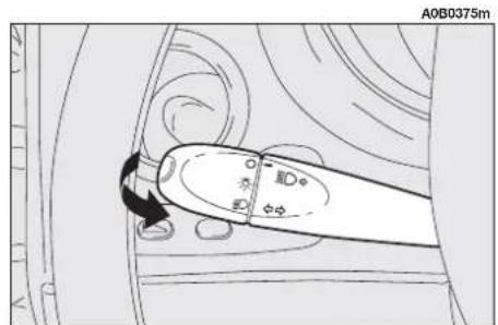
A0B0373m Fig. 70Flashing (fig. 72)
The headlights are flashed by pulling the lever towards the steering wheel (unstable position) regardless of the position of the knurled ring. The warning light on the instrument panel will come on at the same time.
WARNING Only the main-beam lights are flashed. To avoid penalties, follow local regulations.
Direction indicators (fig. 73)
Moving the lever to the stable position will: up - engage the right-hand direction indicators.
down - engage the left-hand direction indicators.
One of the warning lights ( or ) will come on on the instrument panel at the same time.
The lever is returned to its home position automatically and the indicators are switched off when the steering wheel is straightened.
WARNING If you wish to signal a rapid change of direction involving only a minimum movement of the steering wheel, the lever can be moved up or down without clicking (unstable position). When released the lever will return to its home position.

text_image
A0B0374mfig. 71
The right-hand lever is used to operate the windscreen wiper and windscreen washer. The control used to activate the windscreen washers also activates the headlights washers, if fitted.
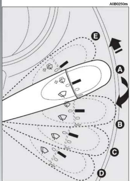
text_image
A0B0250m E A B C Dfig. 74
Windscreen wiper - windscreen washer (fig. 74-75)
The lever can be moved to five different positions corresponding to:
A - Stationary (off).
B - Intermittent.
With the lever in position (B), turning the ring (F) four possible intermittent speeds are obtained:
■ = intermittent slow.
= intermittent medium.
= intermittent medium-fast.
= intermittent fast.

text_image
A0B0377m Ffig. 75
C - Continuous, slow.
D - Continuous, fast.
E - Fast, temporary (unstable position).
Operation in position (E) is limited to the time the lever is held in this position. When the lever is released, it returns to position (A) automatically stopping the wiper.
"INTELLIGENT WASHING" FUNCTION
Pulling the lever towards the steering wheel (fig. 76) (unstable position) operates the windscreen washer.
Keeping the lever pulled, with only one movement it is possible to operate the washer jet and the wiper at the same time; indeed, the latter comes into action automatically if the lever is pulled for more than half a second.
The wiper stops working a few strokes after releasing the lever; a further "cleaning stroke" after a few seconds completes the wiping operation.
Rain sensor (for versions/markets where applicable) (fig. 77)
The rain sensor (A), fitted only on certain versions, is an electronic device combine with the windscreen wiper which has the purpose of automatically adjusting the number of wipes during intermittent operation, to intensity of the rain.
All the other functions controlled by the right-hand lever remain unchanged.
The rain sensor is activated automatically moving the right-hand lever to position (B-fig. 74) and it has a range of adjustment that gradually varies between wiper stationary (no wiping) when the windscreen is dry, to wiper at first continuous speed (continuous, slow) with heavy rain.
Turn ring (F-fig. 75) to set the rain sensor sensitivity level:
= low sensitivity
= medium ensitivity
= high sensitivity.
Operating the windscreen washer with the rain sensor activated (lever at position B) the normal washing cycle is performed at the end of which the rain sensor resumes its normal automatic function.
Turning the ignition key to STOP the rain sensor is deactivated and the next time the engine is started (MAR position) it will not be reactivated even if the lever has remained in position (B). In this case to activate the rain sensor, simply move the lever to (A) or (C) and then back to (B).
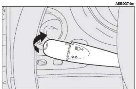
text_image
A0B0374m Φ1 Φ2 Φ3fig. 76

text_image
A0B0012m Afig. 77
When the rain sensor is reactivated, the wiper performs at least one stroke, even if the windscreen is dry, to indicate that reactivation has occurred.
WARNING In case of failure of the right-hand stroke or rain sensor, windscreen wiper operation with the right-hand lever at (B) shall take place in intermittent mode.
The rain sensor is located behind the inner rear-view mirror in contact with the wind-screen and inside the area cleaned by the wiper and it controls an electronic control unit which in turns controls the wiper motor.
At each start, the rain sensor automatically stabilises at a temperature of about 40^ C to eliminate any condensation from the control surface and prevent the formation of ice.
The rain sensor is able to detect and automatically adapt to the presence of the following particular conditions which require different sensitivity:
— impurities on the control surface (salt, dirt, etc.);
— streaks of water caused by worn wiper blades;
— difference between day and night (the human eye is more disturbed during the night by the wet glass surface).
Headlight washers (fig. 78) (optional for versions/markets where applicable)
These are operated when the sidelights are on and the windscreen washer is switched on.
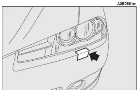
natural_image
Line drawing of a car's front dashboard and side panel, showing no text or symbolsfig. 78
CRUISE CONTROL (optional for versions/ markets where applicable)
GENERAL
The speed regulator (CRUISE CONTROL), with electronic control, makes it possible to drive the car at the required speed without pressing the accelerator pedal. This reduces driving fatigue on motorways, especially during long journeys because the speed memorised is automatically maintained.
WARNING The device can only be engaged at speeds between 30 and 190 km/h.
The device may only be engaged in the 4^th , 5^th or 6^th gear. Travelling downhill with the device engaged, the car speed may increase more than the memorised one, due to the change in the engine load.
The device is disengaged automatically in any one of the following cases:
— pressing the brake pedal;
— pressing the clutch pedal;
— if the VDC, ASR system cuts in;
— with Selespeed or Q-System transmission if a gear is changed;
— if car speed is below the set limit.
CONTROLS (fig. 79)
Cruise Control is controlled by the ON/OFF knurled ring (A), by the +/- ring (B) and by the RCL button (C).
Ring (A) has two positions:
- OFF: in this position the device is deactivated;
— ON: is the normal operating position of the device: the warning light ⚙ on the check panel turns on.
Ring (B) serves for memorising and maintaining the car speed or for increasing or lowering the speed memorised.
Turn the ring (B) to (+) to memorise the speed reached or increase the speed memorised.
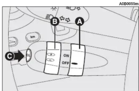
text_image
A0B0055m km B A C ON OFFfig. 79
Turn the ring (B) to (—) to lower the speed memorised.
Each time the ring is actuated (B) the speed increases or lowers by about 1.5 km/h.
Keeping the ring turned the speed changes continuously. The new speed reached will be maintained automatically.
The RCL button (C) resets the memorised speed.
WARNING Turning the ignition key to STOP or the ring (A) to OFF, the speed memorised is cleared and the system is switched off.
The ring (A) can be constantly left to ON without damaging the device. However, we suggest to disconnect the device when it is not used, turning the ring to OFF, to avoid fortuituous speed memorisations.
TO MEMORISE THE SPEED
Move the ring (A) to ON and take the car to the required speed normally. Turn the ring (B) to (+) for at least three seconds, then release it. The car speed is memorised and it is therefore possible to release the accelerator pedal.
The car will continue to travel at the memorised constant speed until one of the following condition takes place:
— pressing the brake pedal;
— pressing the clutch pedal;
— if the VDC, ASR system cuts in;
— with Selespeed or Q-System transmission if a gear is changed.
WARNING In the case of need (when overtaking for instance) acceleration is possible simply pressing the accelerator pedal; later, releasing the accelerator pedal, the car will return to the speed memorised previously.
TO RESET THE MEMORISED SPEED
If the device has been disengaged for example pressing the brake or clutch pedal, the memorised speed can be reset as follows:
— accelerate gradually until reaching a speed approaching the one memorised;
— engage the gear selected at the time of speed memorising ( 4^th , 5^th or 6^th speed);
- press the RCL button (C).
TO INCREASE THE MEMORISED SPEED
The speed memorised can be increased in two ways:
1) pressing the accelerator and then memorising the new speed reached (turning the ring (B) for more than three seconds);
or
2) momentaneously turning the ring (B) to (+): each pulse of the ring will correspond to a slight increase in speed (about 1.5 km/h) while pressing continuously will correspond to a continuous speed increase. Releasing the ring (B) the new speed will be memorised automatically.
TO REDUCE THE MEMORISED SPEED
The speed memorised can be reduced in two ways:
1) disengaging the device (for instance pressing the brake pedal) and then memorising the new speed (turning the ring (B) to (+) for at least three seconds);
2) keeping the ring pressed (B) at (−) until reaching the new speed which will be memorised automatically.
RESETTING THE MEMORISED SPEED
The memorised speed is automatically reset turning off the engine or moving the ring (A) to OFF.

WARNING
When travelling with the cruise control on, do not be gearshift lever to neutral.

WARNING
The cruise control may only be engaged at speeds between 30 and 190 km/h.

WARNING
It is advisable to engage the cruise control only when the conditions of the traffic or road so permit under completely safe conditions: i.e.: straight and dry roads, dual carriageways or motorways, flowing traffic and smooth road surface. Do not engage the device in town or in heavy traffic conditions.

WARNING
If the device is faulty or not working, turn the ring OFF and contact Alfa Romeoized Services after checking the protection fuse is intact.
DASHBOARD
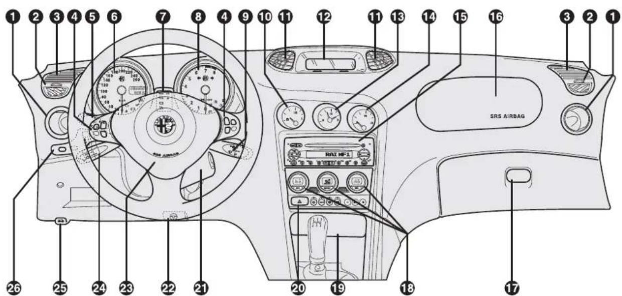
text_image
SRS AIRBAG 1 2 3 4 5 6 7 8 9 10 11 12 13 14 15 16 3 2 1 26 25 24 23 22 21 20 19 18 17A0B0570m
fig. 80
1. Side air outlets - 2. Defrosting/demisting vents for side windows - 3. Upper side vents - 4. Radio controls on the steering wheel (where applicable) - 5. Outside lights control lever - 6. Speedometer (mileage recorder) - 7. Check panel - 8. Rev counter - 9. Windscreen wiper control lever - 10. Fuel level gauge - 11. Centre air vents - 12. Infocenter Display - 13. Clock - 14. Engine coolant temperature gauge - 15. Sound system (where required) - 16. Passenger's Air bag - 17. Glove box - 18. Controls for heating, ventilation and climate control - 19. Ashtray and cigar lighter - 20. Hazard warning lights switch - 21. Ignition switch - 22. Steering wheel lock/release lever - 23. Driver's Air bag and horns - 24. Cruise Control control lever (if provided) - 25. Bonnet opening lever - 26. Set of controls: instrument panel lighting adjustment, trip meter reset and headlamp aiming device.
INSTRUMENT CLUSTER
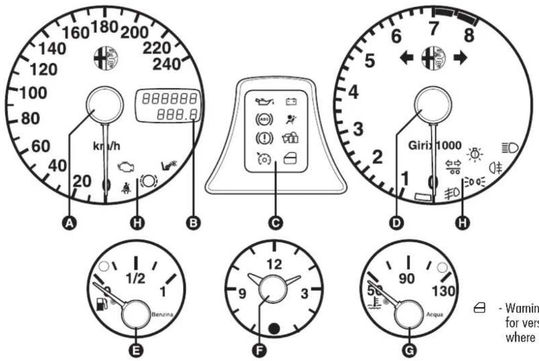
- Warning light fitted for versions/markets where applicable
A0B0584m
A. Speedometer (mileage recorder) - B. Odometer with double counter (total and partial) display - C. Check panel - D. Rev counter - E. Fuel level gauge with reserve warning light - F. Clock - G. Engine coolant temperature gauge with maximum temperature warning light - H. Warning lights.
fig. 81 - T.SPARK versions

[NO TEXT]
Warning light fitted only on Selespeed gearbox versions
6
Warning light fitted for versions/markets where applicable
A0B0695m
A. Speedometer (mileage recorder) - B. Odometer with double counter (total and partial) display - C. Check panel - D. Rev counter - E. Fuel level gauge with reserve warning light - F. Clock - G. Engine coolant temperature gauge with maximum temperature warning light - H. Warning lights - L. Selespeed gearbox display (where fitted).
fig. 81a - JTS and T.SPARK (equipped with VDC system)
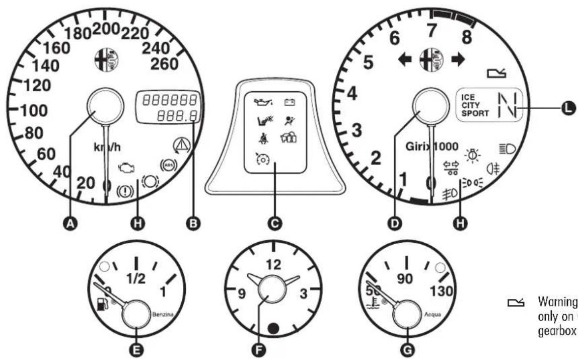
text_image
180 200 220 160 240 140 260 120 100 80 60 40 kr/h 888888 888.8 A H B C D H ICE CITY SPORT Girix 1000 1/2 1 Benzina E F G 90 130 Acqua Warning only on C gearbox
Warning light fitted only on Q-System gearbox versions
A0B0696m
A. Speedometer (mileage recorder) - B. Odometer with double counter (total and partial) display - C. Check panel - D. Rev counter - E. Fuel level gauge with reserve warning light - F. Clock - G. Engine coolant temperature gauge with maximum temperature warning light - H. Warning lights - L. Q-System gearbox display (where fitted).
fig. 82 - 2.5 V6 24V versions
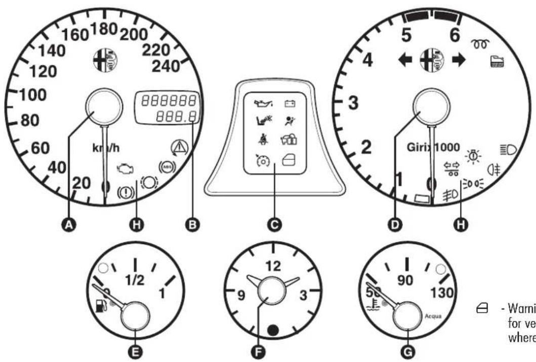
text_image
160 180 200 140 120 100 80 60 40 20 kr/h 888888 888.8 A H B C 5 6 4 3 2 Girix 1000 1 D H E 1/2 1 9 3 12 F 90 130 Acqua G - Warni for ve where
- Warning light fitted for versions/markets where applicable
A0B0586m
A. Speedometer (mileage recorder) - B. Odometer with double counter (total and partial) display - C. Check panel - D. Rev counter - E. Fuel level gauge with reserve warning light - F. Clock - G. Engine coolant temperature gauge with maximum temperature warning light - H. Warning lights.
fig. 83 - JTD versions (equipped with VDC system)

text_image
160 180 200 140 120 100 80 60 40 20 kr/h 888888 888.8 A H B C 5 6 4 3 2 Girix 1000 1 D H E 1/2 1 9 3 12 F 90 130 Acqua G - Warning for ver- where- Warning light fitted for versions/markets where applicable
A0B0597m
A. Speedometer (mileage recorder) - B. Odometer with double counter (total and partial) display - C. Check panel - D. Rev counter - E. Fuel level gauge with reserve warning light - F. Clock - G. Engine coolant temperature gauge with maximum temperature warning light - H. Warning lights.
fig. 83a - JTD versions
REV COUNTER
The rev. counter shows engine rpm. The needle pointed to the danger area (red) indicates excessive high engine speed. Do not drive for long periods with the needle in this area.
WARNING The electronic injection control system gradually shuts off the flow of fuel when the engine is "over-revving" resulting in a gradual loss of engine power.
The rev counter may, when the engine is idling, indicate gradual or sudden increase of engine revs as the case may be; such behaviour is normal and must not be interpreted as a faulty condition as it occurs during normal operation, for instance when climate control or electric fan are switched on. In particular, slow revs variation helps keep the battery charged.
FUEL GAUGE AND RESERVE WARNING LIGHT
This shows the amount of fuel left in the fuel tank.
This warning light ● comes on to indicate that approximately 7 litres of fuel are left in the tank.
WARNING Under certain conditions (heavy slopes, for instance), the reading on the gauge may differ from the actual amount of fuel in the tank and changes in level may be indicated late.
This condition falls within the operation logics of the electronic control circuit to avoid highly unstable readings due to swaying of the fuel when travelling.
WARNING Refuelling shall always be performed with engine off and ignition key to STOP. If the engine is off but the key is to MAR, a wrong fuel level could temporarily be indicated. This is due to the internal system control logic and cannot be considered as a system malfunctioning.
ENGINE COOLANT TEMPERATURE GAUGE AND MAXIMUM TEMPERATURE WARNING LIGHT
This shows the temperature of the engine coolant fluid and begins when the fluid temperature exceeds approx. 50°C.
The pointer should normally be towards the middle of the scale. If the pointer reaches the higher temperature values of the scale (red area), the request for vehicle performance should be decreased.
The illumination of the warning light ● (together with the message shown by the Infocenter display) indicates an excessive temperature of the engine cooling fluid. In this case, stop the car and contact Alfa Romeo Authorized Services.
WARNING The temperature of the engine coolant may rise towards the maximum values (red) when the vehicle is driven at low speeds, especially when the ambient air temperature is high. In this case, the vehicle should be stopped and the engine switched off for a few minutes after which the journey can be resumed, preferably at a higher speed.
MILEAGE DISPLAY (with double meter display)
The display shows:
— the mileage on the first line (6 figures)
— the trip meter on the second line (4 figures)
To reset the trip meter, keep button (A-fig. 84) pressed for a few seconds.
INFOCENTER DISPLAY RHEOSTAT LIGHTS ADJUSTMENT (where required)
This function makes it possible to adjust the brightness (dimming/brightening) of the Infocenter display during night and day.
To perform the desired brightness adjustment (night or day), use buttons + or -, bearing in mind that:
— if the outside lights are on, the message BRIGHTN. ADJUST. NIGHT will appear on the display (fig. 85)
— if the outside lights are OFF, the message BRIGHTN. ADJUST. DAY will appear on the display (fig. 86).
Pressing button INFO, or after about 5 seconds from last operation performed, returns to previous screen.
WARNING During failure indication displaying, brightness cannot be adjusted since under these conditions the display gets automatically to max. brightness.
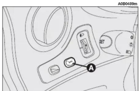
text_image
A0B0489m SET 0 A C Afig. 84

text_image
A0B2124g BRIGHTN.AJUST. NIGHT MIN MAXfig. 85
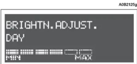
text_image
A0B2125g BRIGHTN.ADJUST. DAY MIN MADfig. 86
INFOCENTER DISPLAY (where required)
The Infocenter display is able to display all the useful and necessary information during driving, in particular:
INFORMATION AVAILABLE ON STANDARD SCREEN
- Date (A-fig. 87)
- Outside temperature (B)
- Failure and warning symbol (e.g.: possible presence of ice on the road C).
The standard screen will remain on until a function is activated which requires being shown on the display (e.g. "Infocenter display rheostat lights adjustment").
INFORMATION ABOUT VEHICLE CONDITION (for each event)
— Scheduled maintenance programme expiry
— Trip computer information
— Rheostat brightness adjustment
— Engine oil level (only JTD versions).
Moreover, a menu is available which allows the driver to perform, by operating the control buttons (see "Control buttons" in the next pages) the following controls and settings:
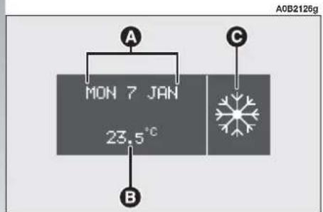
text_image
A0B2126g MON 7 JAN 23.5°C B Cfig. 87
Set-up menu
SPEED LIMIT
— Switching on/off the relevant signal (ON/OFF)
— Speed limit setting
TRIP B ON/OFF
- Switching on/off the relevant function (ON/OFF)
DATE SETTING/TIME SETTING
— Day setting
— Month setting
— Year setting
— Hour setting
— Minute setting
LANGUAGE SELECTION
— Setting the language for the messages shown on the display
UNITS SELECTION
— Selection of the following units: km or mi (miles), °C or °F, l/100 km or km/l
WARNING/FAILURE BUZZER VOLUME SETTING
— Volume setting of warning/failure buzzer
"WINTER" TYRES SPEED LIMIT
— Switching on/off the relevant function (ON/OFF)
— Setting the limit speed value among the available ones (160 km/h, 190 km/h or 210 km/h)
PROGRAMMED MAINTENANCE
— Displaying the expiry date of the next car service check (strictly related to the Programmed Maintenance Schedule)
DISPLAY CONTRAST ADJUSTMENT
— Infocenter display graphics brightness setting (dimming/brightening)
DEFAULT VALUE RESET
— Switching on/off the relevant function (ON/OFF)
EXIT MENU
— Exiting the menu
WARNING The use of polarized glasses may reduce Infocenter display readability.
CONTROL BUTTONS (fig. 88-89)
To make use of the information that the Infocenter display (with the key in the MAR position) is able to provide, you should first get familiar with the relevant control buttons (placed on the central console aside the climate control/ventilation controls and on top of the left lever for the Trip computer function) and use them in accordance with the descriptions below. It is also recommended that you read over this chapter before performing any operation.
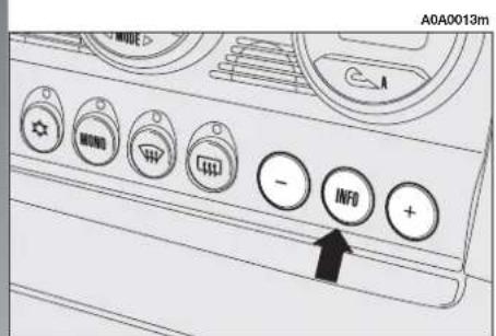
text_image
A0A0013m MOND INFO +fig. 88


INFO, ⊕, ⊖ buttons
Depending on the cases: to scroll the menu screens and their respective options upwards or to increase the displayed value
A single press for less than 2 seconds (pulse), shown by INFO.1 in the following screens, to confirm the desired option and/or switch to the next screen or access the menu
A single press for more than 2 seconds, shown by INFO2 in the following screens, to confirm the desired option and return to the previous screen
Depending on the cases: to scroll the menu screens and their respective options downwards or to decrease the displayed value
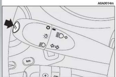
text_image
A0A0014m kmfig. 89

SET button
A single press for less than 2 seconds (pulse), shown by SET1 in the following screens, to scroll the different Trip computer information screens
A single press for more than 2 seconds, shown by SET 2 in the following screens, to reset the Trip computer information (reset) and initiate a new mission
MENU DESCRIPTION
The menu is made up of a set of functions arranged in a "circular fashion", which can be selected by means of buttons + and -, for access to the different select operations and settings (see the examples "LANGUAGE" and "DATE" in the table below); for further details, also refer to "Access to the menu screen" in the following pages.

flowchart
graph TD
    A["MENU OFF\nSPEED\nTRIP B"] --> B["SPEED"]
    B --> C["TRIP B\nDATE\nLANGUAGE"]
    C --> D["DATA\nLANGUAGE UNITS"]
    D --> E["LANGUAGE\nUNITS BUZZER"]
    E --> F["UNITS BUZZER\nWINTER TYRES"]
    F --> G["Buzzer"]
    G --> H["WINTER TYRES\nSERVICE CONTRAST"]
    H --> I["SERVICE\nCONTRAST\nDEFAULT VALUES"]
    I --> J["CONTRAST\nDEFAULT VALUES\nMENU OFF"]
    J --> K["DEFAULT VALUES\nMENU OFF\nSPEED"]
    K --> L["MENU OFF"]
    L --> M["SPEED"]
    M --> N["SPEED"]
    N --> O["TIME1"]
    O --> P["Day\nMinutes\nHour\nMonth\nYear"]
    P --> Q["INFO1"]
    Q --> R["English\nDeutsch\nItaliano\nPortuguese\nNederlands\nEspañol\nFrançais"]
INITIAL CHECK
By turning the ignition key to the MAR position, the Infocenter display will show the message CHECK ACTIVE: this indicates the start of the diagnosis phase for all the electronic systems available on the vehicle; this phase lasts a few seconds (in diesel versions only, the Infocenter display is able to provide the engine oil level indication too, see following paragraph "Engine oil level check"). If, during this phase, no anomaly is found and after the engine has been started, the display will show the message CHECK OK.
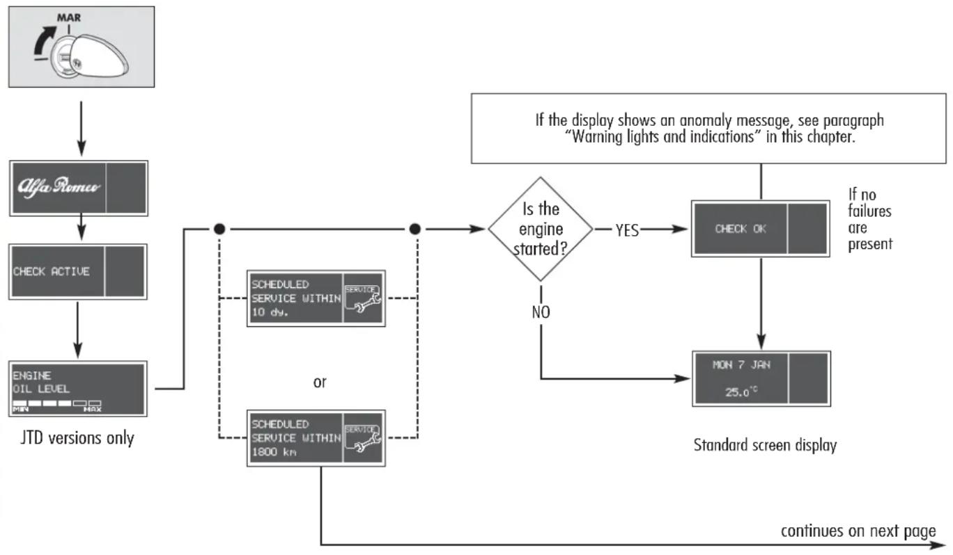
flowchart
graph TD
    A["Mar"] --> B["Alfa Romeo"]
    B --> C["CHECK ACTIVE"]
    C --> D["ENGINE OIL LEVEL MAX"]
    D --> E{Is the engine started?}
    E -->|YES| F["CHECK OK"]
    E -->|NO| G["SCHEDULED SERVICE WITHIN 10 dy."]
    G --> H["or"]
    H --> I["SCHEDULED SERVICE WITHIN 1800 km"]
    I --> J["continues on next page"]
    F --> K["Standard screen display"]
    K --> L["MON 7 JAN 25.0°C"]
    L --> M["If no failures are present"]
    M --> N["If the display shows an anomaly message, see paragraph "Warning lights and indications" in this chapter."]
    N --> O["JTD versions only"]
continued from previous page
The Programmed Maintenance Schedule includes car maintenance every 20,000 km (or 12,000 miles) or one year; this is shown automatically, with the ignition key at MAR, starting from 2,000 km (or 1,240 miles) or 30 day from this deadline and it is shown again every 200 km (or 124 miles) or 3 days. When a programmed maintenance interval ("coupon") is near to come, turning the ignition key to MAR, will display the message SCHEDULED SERVICE WITHIN followed by the number of kilometers, days or miles to go before vehicle maintenance. The PROGRAMMED MAINTENANCE message is displayed in km, mi or days, according to the approaching service interval. At the very moment the value of 0 km, 0 miles or 0 days is reached, the display will show, every time the ignition key is turned to MAR, the message SCHEDULED SERVICE EXPIRED, followed by the number of kilometers, miles or days. In this case, to reset this visual information contact Authorised Alfa Romeo Services.
Engine oil level check (JTD versions only)
By turning the ignition key to the MAR position, the Infocenter display will show the engine oil level display for about 3 seconds. During this phase, to clear the display and move to the following screen, press INFO!
WARNING To ensure correct reading of the engine oil level, the check must be carried out with the vehicle on level ground.
The following display in fig. 90 refers to correct engine oil level. As the oil level gradually falls, the full bars go off leaving room for the empty bars.
The following fig. 91 and fig. 92 refer to the display with an oil level below the foreseen minimum. Under this condition, the bars are all empty with symbol and warning messages.
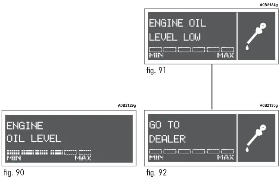
flowchart
graph TD
    A["ENGINE OIL LEVEL LOW"] --> B["A0B2134g"]
    A --> C["A0B2135g"]
    D["GO TO DEALER"] --> E["A0B2135g"]
    D --> F["A0B2135g"]

Restore correct engine oil level (see paragraph "Checking fluid levels" in "Car maintenance").
The following refers to the display (fig. 93) (appearing for about 3 seconds) with an oil level above the foreseen maximum. Under this condition the bars are all full.

Contact Alfa Romeo Authorized Services to have the engine oil restored to ect level.

Do not add oil with different characteristics from those of the oil already the engine (see "Fluids and units" in chapter "Car main-e").
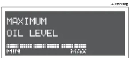
text_image
A0B2136g MAXIMUM OIL LEVEL MIN MAXfig. 93
ACCESS TO THE MENU SCREEN
After the INITIAL CHECK, it is possible to access the menu screen by pressing button INFO1.
To navigate use the + and - buttons.
WARNING If you access the Menu and no setting/adjustment is made within about 60 seconds, the system automatically leaves the Menu and displays the screen previously set. In this case, the latest setting selected but not confirmed (by means of button INFO ^1 ) is not stored; therefore, the operation must be performed again.
— When the car is running, only the short menu can be accessed (SPEED LIMIT setting).
— When the car is stopped, the extended menu can be accessed.
The following table gives the description of the cases provided.

flowchart
graph TD
    A["See INITIAL CHECK"] --> B["MON 7 JAN 25.0°C"]
    B --> C["INFO1"]
    C --> D{Is the car moving?}
    D -->|YES| E["Short menu screen"]
    D -->|NO| F["SPEED TRIP B DATE"]
    E --> G["SPEED LIMIT 30 km/h OFF ON"]
    F --> H["Extended menu screen"]
SPEED LIMIT (SPEED)
With this function it is possible to set the car speed limit which, if exceeded, automatically sounds a buzzer and displays a specific message to alert the driver. To set the limit speed, proceed as follows:
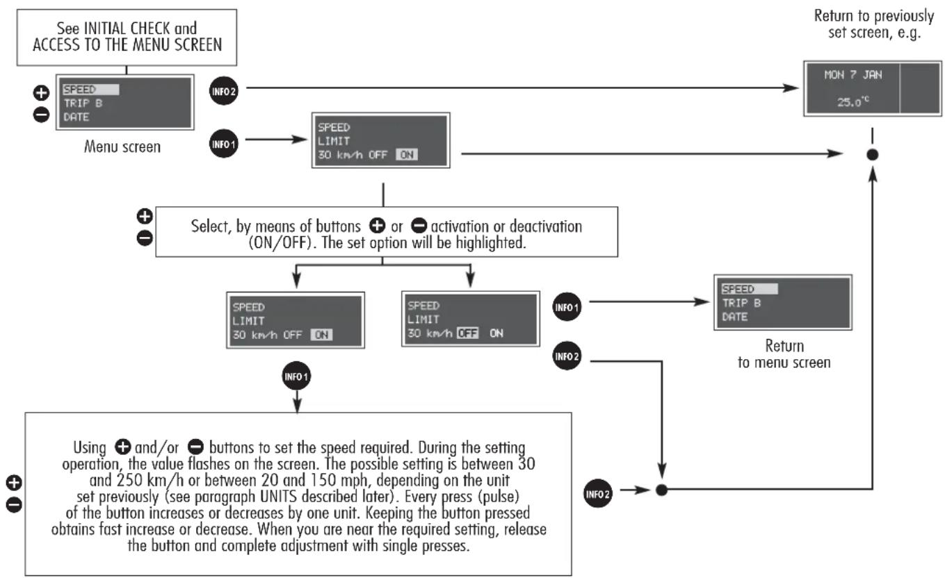
flowchart
graph TD
    A["See INITIAL CHECK and ACCESS TO THE MENU SCREEN"] --> B["Menu screen"]
    B --> C["SPEED<br>TRIP B<br>DATE"]
    C --> D["INFO2"]
    D --> E["SPEED<br>LIMIT<br>30 km/h OFF ON"]
    E --> F["Return to previously set screen, e.g. MON 7 JAN<br>25.0°C"]
    F --> G["Select, by means of buttons + or - activation or deactivation (ON/OFF). The set option will be highlighted."]
    G --> H["SPEED<br>LIMIT<br>30 km/h OFF ON"]
    G --> I["SPEED<br>LIMIT<br>30 km/h OFF ON"]
    H --> J["INFO1"]
    I --> K["INFO2"]
    J --> L["Return to menu screen"]
    K --> M["INFO2"]
    L --> N["Using + and/or - buttons to set the speed required. During the setting operation, the value flashes on the screen. The possible setting is between 30 and 250 km/h or between 20 and 150 mph, depending on the unit set previously (see paragraph UNITS described later). Every press (pulse) of the button increases or decreases by one unit. Keeping the button pressed obtains fast increase or decrease. When you are near the required setting, release the button and complete adjustment with single presses."]
Speed limit exceeded indication
As soon as the vehicle exceeds the set speed limit, the following display is shown automatically, together with the sounding of a buzzer.
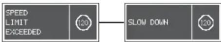
flowchart
graph LR
    A["SPEED LIMIT EXCEEDED"] --> B["120"]
    B --> C["SLOW DOWN"]
    C --> D["120"]
Example of display when the set value is 120 km/h
TRIP B ON/OFF (TRIP B)
With this option it is possible to turn ON or OFF the TRIP B function (partial trip) which displays the figures relating to: TRAVEL DISTANCE B, AVERAGE CONSUMPTION B, AVERAGE SPEED B, TRAVEL TIME B during a "partial mission".
For further details, see "General Trip - Trip B"
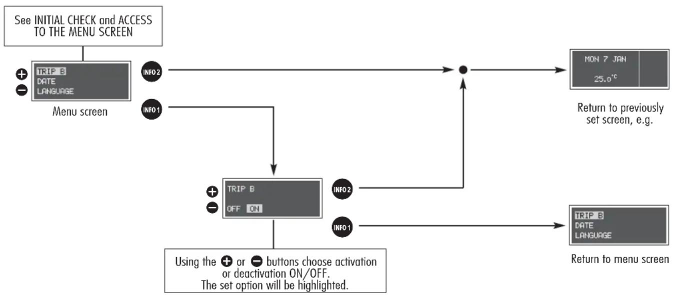
flowchart
graph TD
    A["See INITIAL CHECK and ACCESS TO THE MENU SCREEN"] --> B["Menu screen"]
    B --> C["TRIP B DATE LANGUAGE"]
    C --> D["INFO2"]
    C --> E["INFO1"]
    D --> F["TRIP B OFF ON"]
    E --> F
    F --> G["INFO2"]
    F --> H["INFO1"]
    G --> I["•"]
    H --> J["•"]
    I --> K["MON 7 JAN 25.0°C"]
    J --> L["TRIP B DATE LANGUAGE"]
    L --> M["Return to menu screen"]
    N["Using the + or - buttons choose activation or deactivation ON/OFF.<br>The set option will be highlighted."] --> F
DATE SETTING/TIME SETTING (DATE)
To set the date (day - month - year) and the time (hours-minutes), proceed as follows:

flowchart
graph TD
    A["See INITIAL CHECK and ACCESS TO THE MENU SCREEN"] --> B["Menu screen"]
    B --> C{DAY}
    C --> D["07:01:2002"]
    D --> E["INFO1"]
    E --> F["INFO2"]
    F --> G["MONTH"]
    G --> H["07:01:2002"]
    H --> I["INFO1"]
    I --> J["INFO2"]
    J --> K["YEAR"]
    K --> L["07:01:2002"]
    L --> M["INFO1"]
    M --> N["INFO2"]
    N --> O["Return to previously set screen, e.g.:"]
    O --> P["MON 7 JAN 25.0°C"]
    P --> Q["continues on next page"]
    Q --> R["Each press (pulse) on the + or - buttons increases or decreases by one unit. Keeping the corresponding button pressed obtains fast increase or decrease. When you are near the required value, release the control and complete adjustment by single presses."]
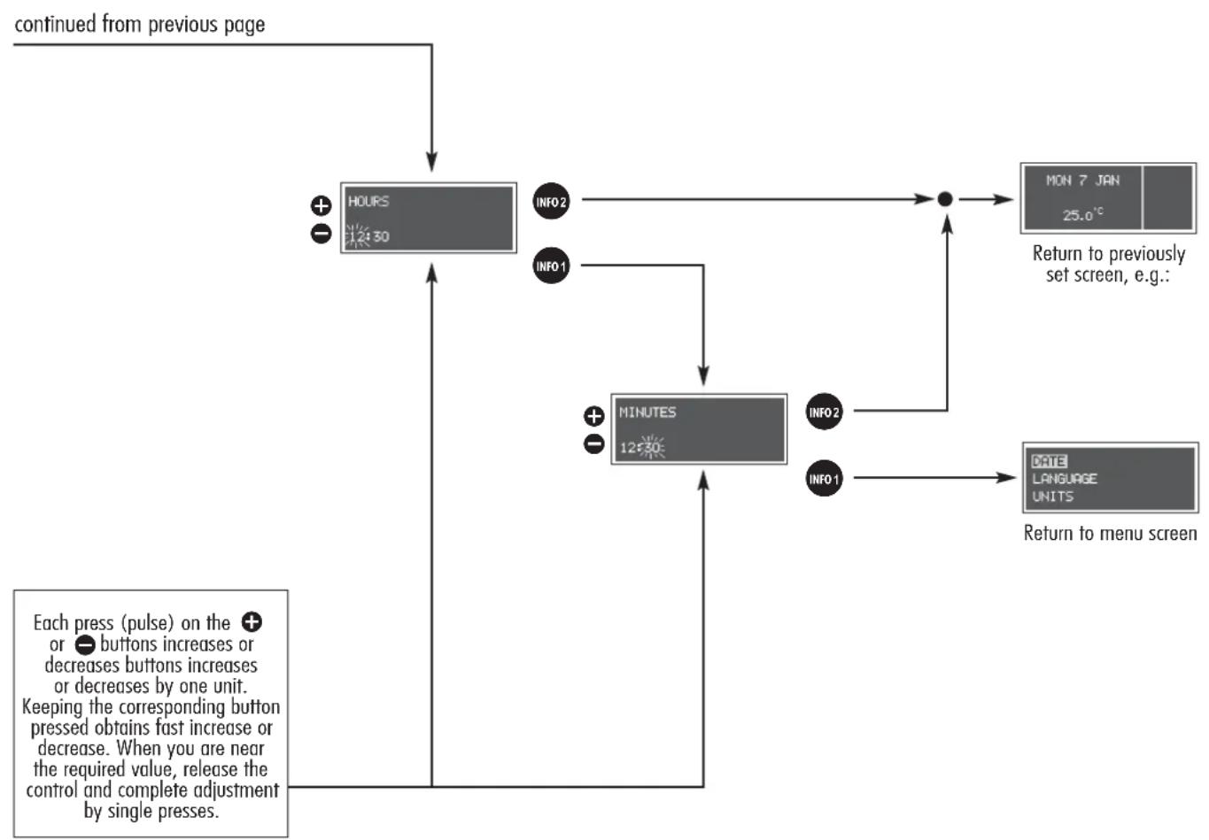
flowchart
graph TD
    A["continued from previous page"] --> B["HOURS 12:30"]
    B --> C["INFO2"]
    B --> D["INFO1"]
    C --> E["MINUTES 12:30"]
    D --> E
    E --> F["INFO2"]
    E --> G["INFO1"]
    F --> H["MON 7 JAN 25.0°C"]
    G --> I["DATE LANGUAGE UNITS"]
    H --> J["Return to previously set screen, e.g.:"]
    I --> K["Return to menu screen"]
    L["Each press (pulse) on the + or - buttons increases or decreases buttons increases by one unit. Keeping the corresponding button pressed obtains fast increase or decrease. When you are near the required value, release the control and complete adjustment by single presses."] --> M
LANGUAGE SELECTION (LANGUAGE)
The messages shown on the display can be provided in several languages (Italian, Deutsch, English, Spanish, French, Dutch, Portuguese). To select the required language, proceed as follows:
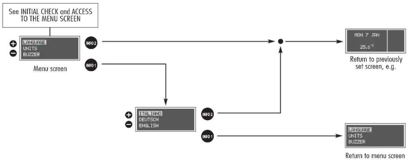
flowchart
graph TD
    A["See INITIAL CHECK and ACCESS TO THE MENU SCREEN"] --> B["Menu screen"]
    B --> C["INFO2"]
    B --> D["INFO1"]
    C --> E["+"]
    D --> F["+"]
    E --> G["ITFLIANO DEUTSCH ENGLISH"]
    F --> H["INFO2"]
    F --> I["INFO1"]
    G --> J["•"]
    H --> J
    I --> J
    J --> K["MON 7 JAN 25.0°C"]
    K --> L["Return to previously set screen, e.g."]
    J --> M["Language UNITS BUZZER"]
    M --> N["Return to menu screen"]
UNITS SELECTION (UNITS)
The display provides information in relation to the unit of measure set. To choose the units, proceed as follows:

flowchart
graph TD
    A["See INITIAL CHECK and ACCESS TO THE MENU SCREEN"] --> B["Menu screen"]
    B --> C["INFO2"]
    B --> D["INFO1"]
    C --> E["Temperature °C °F"]
    D --> E
    E --> F["INFO2"]
    F --> G["Distance km pi"]
    G --> H["INFO1"]
    G --> I["INFO2"]
    H --> J["FUEL CONSUMPT. 1/100km km/1"]
    I --> K["INFO1"]
    J --> L["Return to previously setscreen, e.g. MON 7 JAN 25.0°C"]
    K --> M["Return to menu screen"]
WARNING/FAILURE BUZZER VOLUME SETTING (BUZZER)
The volume of the buzzer that signals any failure or warning to the driver can be adjusted according to a pre-set scale using the + and/or - buttons. To switch OFF or adjust, proceed as follows:

flowchart
graph TD
    A["See INITIAL CHECK and ACCESS TO THE MENU SCREEN"] --> B["BUZZER WINTER TYRES SERVICE"]
    B --> C["Menu screen"]
    C --> D["INFO2"]
    C --> E["INFO1"]
    D --> F["BUZZER OFF MAX"]
    E --> G["INFO2"]
    E --> H["INFO1"]
    F --> I["Return to previously set screen, e.g."]
    G --> J["Return to menu screen"]
    H --> J
    I --> K["MON 7 JAN 25.0°C"]
    J --> L["BUZZER WINTER TYRES SERVICE"]
"WINTER" TYRES SPEED LIMIT (WINTER TYRES)
With this function it is possible to set the speed limit when travelling with winter tyres. The speed limit can be chosen between: 160 km/h, 190 km/h or 210 km/h (see paragraph "Winter tyres" in section "Correct use of the car").
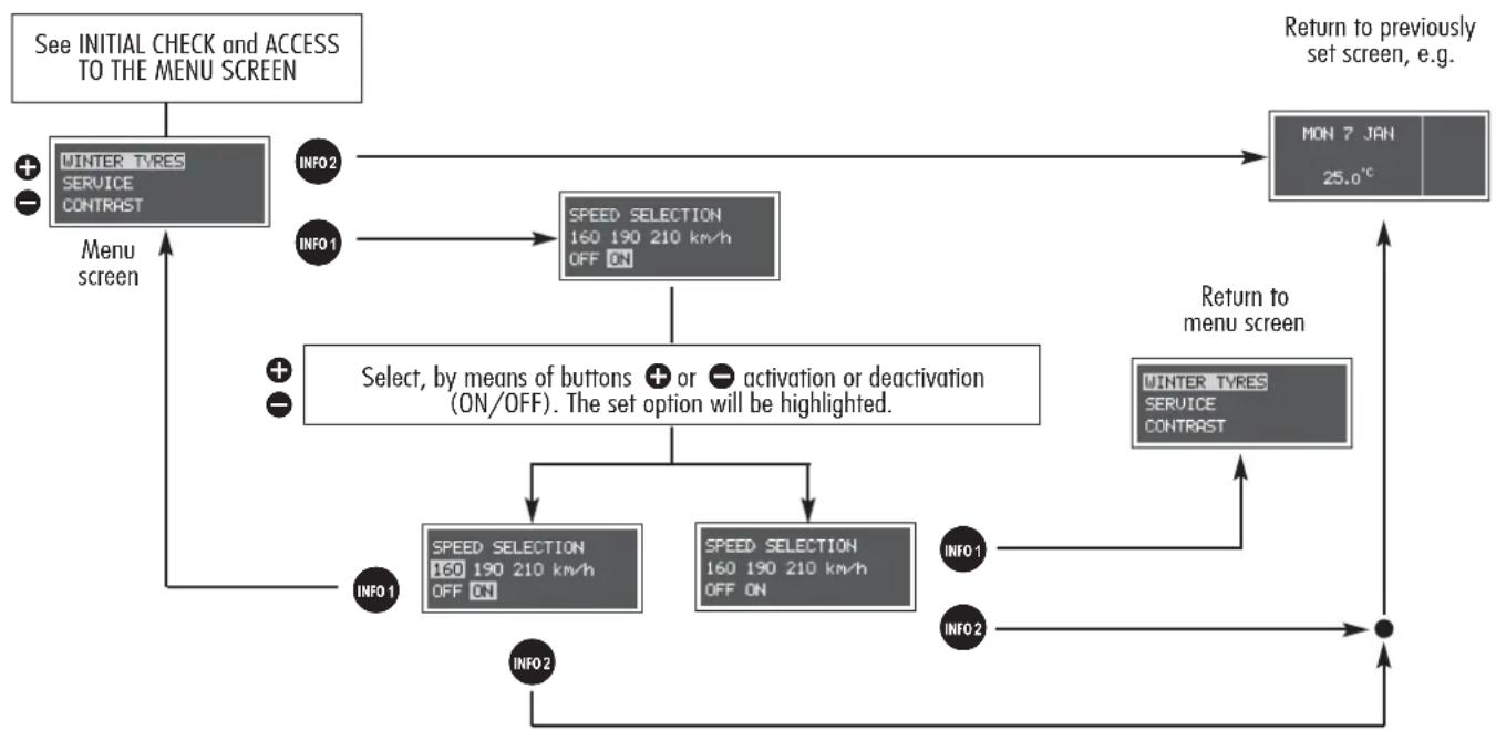
flowchart
graph TD
    A["See INITIAL CHECK and ACCESS TO THE MENU SCREEN"] --> B["WINTER TYRES SERVICE CONTRAST"]
    B --> C["Menu screen"]
    C --> D["INFO2"]
    C --> E["INFO1"]
    D --> F["SPEED SELECTION 160 190 210 km/h OFF ON"]
    E --> F
    F --> G["Select, by means of buttons + or - activation or deactivation (ON/OFF). The set option will be highlighted."]
    G --> H["SPEED SELECTION 160 190 210 km/h OFF ON"]
    G --> I["SPEED SELECTION 160 190 210 km/h OFF ON"]
    H --> J["INFO1"]
    I --> K["INFO2"]
    J --> L["Return to previously set screen, e.g."]
    K --> L
    L --> M["MON 7 JAN 25.0°C"]
    M --> N["Return to menu screen"]
    N --> O["INFO1"]
    N --> P["INFO2"]
PROGRAMMED MAINTENANCE (SERVICE)
With the SERVICE function it is possible to receive information connected with correct vehicle maintenance. To consult this function, proceed as follows:
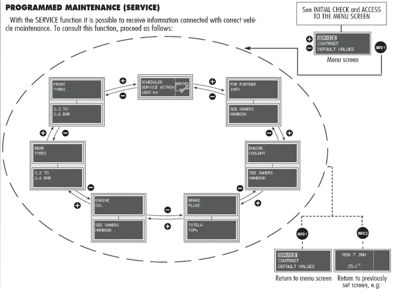
flowchart
graph TD
    A["FRONT TYRES\n2.2 TO 2.6 BAR"] --> B["SCHEDULED SERVICE WITHIN 1800 km"]
    B --> C["FOR FURTHER INFO\nSEE OWNERS HANBOOK"]
    C --> D["ENGINE COOLANT\nSEE OWNERS HANBOOK"]
    D --> E["BRAKE FLUID\nTUTELA TOP+"]
    E --> F["ENGINE OIL\nSEE OWNERS HANBOOK"]
    F --> G["REXR TYRES\n2.2 TO 2.6 BAR"]
    G --> A
    H["Service CONTRAST DEFAULT VALUES\nMON 7 JAN 25.0°C"] --> I["Menu screen\nINFO 1"]
    I --> J["Service CONTRAST DEFAULT VALUES\nINFO 2"]
    J --> K["Return to menu screen\nINFO 1"]
    K --> L["Return to previously set screen, e.g."]
    L --> M["See INITIAL CHECK and ACCESS TO THE MENU SCREEN\nINFO 1"]
WARNING Products shown in the SERVICE screen and to be used for scheduled maintenance could be subject to modifications. Refer to paragraph "Fluids and lubricants" in section "Technical specifications".
SCHEDULED
SERVICE
EXPIRED 0 km
The Programmed Maintenance Schedule includes vehicle maintenance
every 20,000 km (or 12,000 miles) or one year; this is shown
automatically, with the ignition key at MAR, starting from 2,000
km (or 1,240 miles) or 30 day from this deadline and it is shown
again every 200 km (or 124 miles) or 3 days. When a programmed maintenance interval
("coupon") is near to come, turning the ignition key to MAR, will display the message
SCHEDULED SERVICE WITHIN followed by the number of kilometers, days or miles to go
before vehicle maintenance. The PROGRAMMED MAINTENANCE message is displayed in km,
mi or days, according to the approaching service interval. At the very moment the value of 0
km, 0 miles or 0 days is reached, the display will show, every time the ignition key is turned
to MAR, the message SCHEDULED SERVICE EXPIRED, followed by the number of
kilometers, miles or days. In this case, to reset this visual information contact Authorized Alfa
Romeo Services.
DISPLAY CONTRAST ADJUSTMENT (CONTRAST)
This function allows to adjust the Infocenter display brightness (dimming/brightening).
To perform the adjustment, proceed as follows:

flowchart
graph TD
    A["See INITIAL CHECK and ACCESS TO THE MENU SCREEN"] --> B["CONTRAST DEFAULT VALUES MENU OFF"]
    B --> C["INFO2"]
    B --> D["INFO1"]
    C --> E["CONTRAST"]
    D --> E
    E --> F["INFO2"]
    E --> G["INFO1"]
    F --> H["Return to previously set screen, e.g."]
    G --> I["Return to menu screen"]
DEFAULT VALUE RESET (DEFAULT VALUES)
The following function:
— If ON restores: Speed limit, Trip B, Light rheostat, Language, Temperature unit, km/mi unit, Consumption unit, Buzzer, Winter tyres, Contrast, with the following values Speed limit = 120 km/h, Trip B ON, Light rheostat ON = 4, Light rheostat OFF = 1, Language = Italian, Temperature unit = °C, Distance unit = km, Consumption unit = l/100 km, Buzzer = 2, Winter tyres OFF (value set at 160 km/h), contrast value = 3
— If OFF, the above parameter values can be set manually
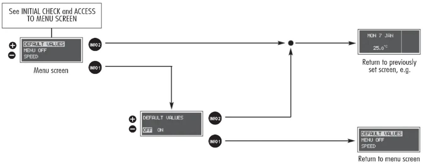
flowchart
graph TD
    A["See INITIAL CHECK and ACCESS TO MENU SCREEN"] --> B["DEFAULT VALUES MENU OFF SPEED"]
    B --> C["INFO2"]
    B --> D["INFO1"]
    C --> E["DEFAULT VALUES OFF ON"]
    D --> E
    E --> F["Return to previously set screen, e.g."]
    F --> G["MON 7 JAN 25.0°C"]
    G --> H["DEFAULT VALUES MENU OFF SPEED"]
    H --> I["Return to menu screen"]
EXIT MENU (MENU OFF)
With this function it is possible to exit the setup menu and return to the previously set screen.

flowchart
graph LR
    A["See INITIAL CHECK and ACCESS TO THE MENU SCREEN"] --> B["Menu screen"]
    B --> C["INFO1"]
    C --> D["Return to previously set screen, e.g."]
GENERAL TRIP - TRIP B
The TRIP COMPUTER function gives information relating to the operating status of the vehicle on the Infocenter display. This function comprises the GENERAL TRIP concerning the complete mission of the car and TRIP B concerning the partial car mission. This function (as shown in the graph below) is contained within the complete mission. Both functions are resettable.
The GENERAL TRIP displays the figures relating to RANGE, TRAVEL DISTANCE, AVERAGE CONSUMPTION, ACTUAL CONSUMPTION, AVERAGE VELOCITY, TRAVELTIME (complete mission time).
The TRIP B (with automatic reset each time at least 2 hours have passed since stopping the engine), displays information concerning TRAVEL DISTANCE B, AVERAGE CONSUMPTION B, AVERAGE SPEED B, TRAVEL TIME B (partial mission time).
Start of journey procedure (reset)
To start a new journey monitored by the GENERAL TRIP, with the ignition key at MAR, press the button with (see "Control buttons").

flowchart
graph LR
    A["Reset GENERAL TRIP\nEnd of complete mission\nStart of new mission"] --> B["Reset TRIP B\nEnd of partial mission\nStart of new partial mission"]
    B --> C["Reset TRIP B\nEnd of partial mission\nStart of new partial mission"]
    C --> D["Reset GENERAL TRIP\nEnd of complete mission\nStart of new mission"]
    D --> E["Reset TRIP B\nEnd of partial mission\nStart of new partial mission"]
    E --> F["Reset TRIP B\nEnd of partial mission\nStart of new partial mission"]
    F --> G["Reset GENERAL TRIP\nEnd of complete mission\nStart of new mission"]
The reset operation (pressing the button) in the presence of the screens concerning the GENERAL TRIP also makes it possible to reset TRIP B. The reset operation (pressing the button) in the presence of only the screens concerning TRIP B makes it possible to reset only the information associated with this function.
WARNING The RANGE and ACTUAL CONSUMPTION information cannot be reset.
WARNING At the beginning of a new mission, due to battery reconnection, the average consumption value is initialised to the "average predefined standard consumption" equal to 9 l/100 km (for 1.6 T.SPARK, 1.8 T.SPARK, 2.0 JTS and 2.0 JTS Selespeed versions), 12 l/100 km (for 2.5 V6 24V and 2.5 V6 24V Q-System versions) and 6.5 l/100 km (diesel versions only).
The TRIP COMPUTER information is displayed in sequence according to the table below.

flowchart
graph TD
    A["See INITIAL CHECK and ACCESS TO THE MENU SCREEN"] --> B["MON 7 JAN 25.0°C"]
    B --> C["RANGE 100 km"]
    C --> D["TRAVEL DISTANCE 95.5 km"]
    D --> E["AVERAGE CONSUMPTION 10 km/1"]
    E --> F["Continues on next page"]

    G["Previously set screen; e.g."] --> B
    H["ACTUAL CONSUMPTION 10 km/1"] --> I["AVERAGE VELOCITY 50 km/h"]
    I --> J["TRAVEL TIME 10:30"]
    J --> K["SET 1"]
    J --> L["SET 2"]
    M["SET 1"] --> C
    N["SET 2"] --> D
    O["SET 1"] --> E
    P["SET 2"] --> J
    Q["SET 1"] --> K
    R["SET 2"] --> L
    S["SET 1"] --> E
    T["SET 2"] --> L

    U["Reset GENERAL TRIP and TRIP B, excluding Range and Actual Consumption (see next paragraph RESET GENERAL TRIP)"]
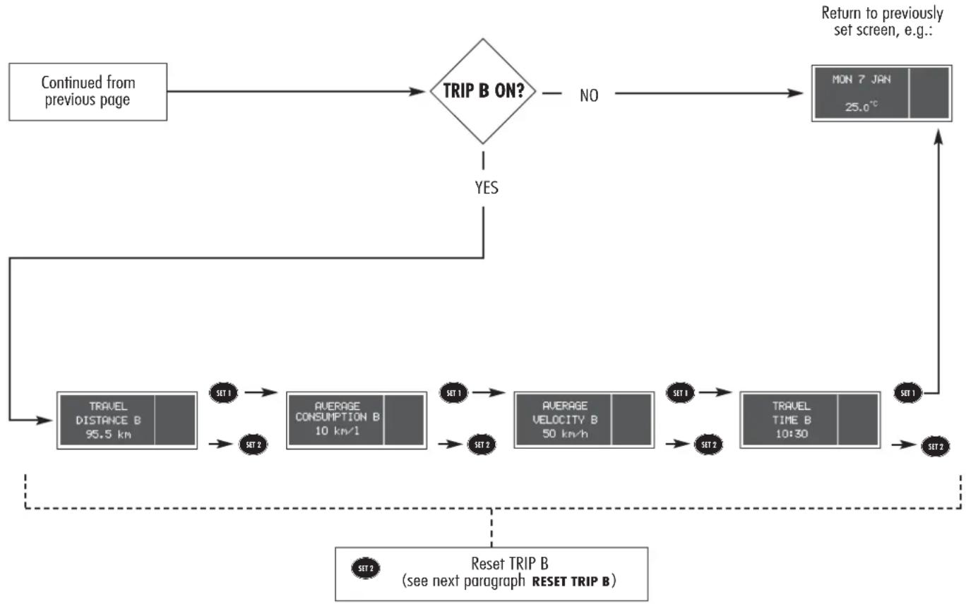
flowchart
graph TD
    A["Continued from previous page"] --> B{TRIP B ON?}
    B -->|YES| C["Return to previously set screen, e.g."]
    B -->|NO| D["MON 7 JAN 25.0°C"]
    C --> E["SET 1"]
    E --> F["TRAVEL DISTANCE B 95.5 km"]
    F --> G["SET 2"]
    G --> H["AVERAGE CONSUMPTION B 10 km/1"]
    H --> I["SET 1"]
    I --> J["AVERAGE VELOCITY B 50 km/h"]
    J --> K["SET 2"]
    K --> L["AVERAGE VELOCITY B 50 km/h"]
    L --> M["SET 1"]
    M --> N["TRAVEL TIME B 10:30"]
    N --> O["SET 1"]
    O --> P["SET 2"]
    P --> Q["SET 2"]
    Q --> R["SET 2"]
    R --> S["SET 2"]
    S --> T["SET 2"]
    T --> U["SET 2"]
    U --> V["SET 2"]
    V --> W["SET 2"]
    W --> X["SET 2"]
    X --> Y["SET 2"]
    Y --> Z["SET 2"]
    Z --> AA["SET 2"]
    AA --> AB["SET 2"]
    AB --> AC["SET 2"]
    AC --> AD["SET 2"]
    AD --> AE["SET 2"]
    AE --> AF["SET 2"]
    AF --> AG["SET 2"]
    AG --> AH["SET 2"]
    AH --> AI["SET 2"]
    AI --> AJ["SET 2"]
    AJ --> AK["SET 2"]
    AK --> AL["SET 2"]
    AL --> AM["SET 2"]
    AM --> AN["SET 2"]
    AN --> AO["SET 2"]
    AO --> AP["SET 2"]
    AP --> AQ["SET 2"]
    AQ --> AR["SET 2"]
    AR --> AS["SET 2"]
    AS --> AT["SET 2"]
    AT --> AU["SET 2"]
    AU --> AV["SET 2"]
    AV --> AW["SET 2"]
    AW --> AX["SET 2"]
    AX --> AY["SET 2"]
    AY --> AZ["SET 2"]
    AZ --> BA["SET 2"]
    BA --> BB["SET 2"]
    BB --> BC["SET 2"]
    BC --> BD["SET 2"]
    BD --> BE["SET 2"]
    BE --> BF["SET 2"]

WARNING Pressing the INFO button returns automatically to the standard screen
After resetting TRIP by pressing the button with SET 2 mode, the display will show the following functions:
Reset GENERAL TRIP
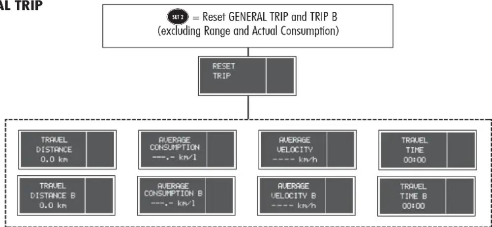
flowchart
graph TD
    A["SET 2 = Reset GENERAL TRIP and TRIP B (excluding Range and Actual Consumption)"] --> B["RESET TRIP"]
    B --> C["TRAVEL DISTANCE 0.0 km"]
    B --> D["AVERAGE CONSUMPTION ---.- km/h"]
    B --> E["AVERAGE VELOCITY ---- km/h"]
    B --> F["TRAVEL TIME 00:00"]
    B --> G["TRAVEL DISTANCE B 0.0 km"]
    B --> H["AVERAGE CONSUMPTION B ---.- km/h"]
    B --> I["AVERAGE VELOCITY B ---- km/h"]
    B --> J["TRAVEL TIME B 00:00"]
Reset TRIP B
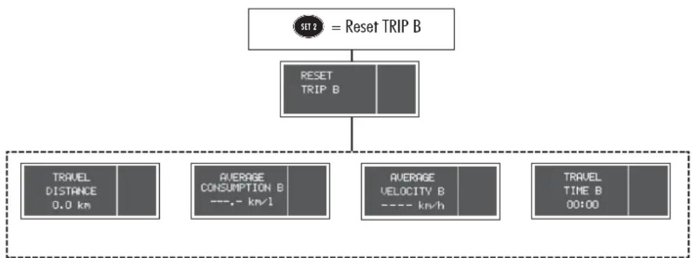
flowchart
graph TD
    A["SET 2 = Reset TRIP B"] --> B["RESET TRIP B"]
    B --> C["TRAVEL DISTANCE 0.0 km"]
    B --> D["AVERAGE CONSUMPTION B ---.- km/1"]
    B --> E["AVERAGE VELOCITY B ---- km/h"]
    B --> F["TRAVEL TIME B 00:00"]
RANGE = This shows the distance (in km or miles) the car can still cover before needing fuel if keeping the same driving conditions. The display will show “----” after the following events:
A) range values lower than 50 km (approx. 31 miles) (after the reduced range warning message),
B) Parking with running engine or car speed lower than 4 km/h for over 5 minutes.
TRAVEL DISTANCE = This shows the distance traveled by the car from the start of the new mission (*).
AVERAGE CONSUMPTION = This shows the average actual consumption in l/km or in l/100 km depending on the unit selected.
ACTUAL CONSUMPTION = This shows the consumption of the car updated every 5 sec. approx. If parking with running engine or in case of speed values lower than 4 km/h the display will show “----”. Actual consumption calculation algorithm, according to the above procedure, restarts as soon as the car speed will be equal to or higher than 4 km/h.
AVERAGE VELOCITY = This shows the average speed of the car as a function of the overall travel time elapsed from the start of the new mission (*).
TRAVELTIME = time elapsed from the start of the new mission (*).
(*) NEW MISSION: this takes place when performing the "manual" reset by pressing the dedicated button.
WARNING GENERAL TRIP is reset automatically when the Distance Traveled is equal to 9999.9 km (or mi), when Travel Time is 99:59 (99 hours and 59 minutes) or after reconnecting the battery.
WARNING If no information is available, all the TRIP COMPUTER parameters display the message “*****” instead of a value, together with the typical description of each parameter. When the normal operation condition is resumed, the count of the various parameters starts again normally, with no reset of the values displayed prior to the failure, nor the start of a new mission.
WARNING LIGHTS AND INDICATIONS
GENERAL WARNING
The failure indications shown on the Infocenter display, together with the buzzer (adjustable) and the turning on of the relevant warning light (if available), are accompanied by specific warning messages (e.g. "Go to dealer", "Switch off eng., do not proceed", etc...). These warnings are concise and precautionary and are intended to suggest the prompt action that the driver should take when a failure occurs. However, these warnings are not to be considered exhaustive and/or alternative to the prescriptions of this Owner's Manual, which must always be read over carefully. When an anomaly occurs always refer to the contents of this chapter.
WARNING When an anomaly occurs, the Infocenter display reaches its maximum brightness. By pressing button INFO the warning messages disappear and the symbol referring to the failure warning is reduced to an icon in the right bottom area of the display.
WARNING The anomaly warnings that appear on the Infocenter display are divided into two categories: very serious and serious anomalies. Very serious anomalies are displayed indefinitely, by interrupting any message previously shown on the display, and are proposed again every time the ignition key is turned to MAR, until the malfunction is eliminated. Moreover, the "cycle" can be interrupted by pressing button INFO: in this case, the symbol referring to the anomaly will be shown in the right bottom area of the display until the malfunction is eliminated.
Serious anomalies are displayed for about 20 seconds and then disappear, but they are proposed again every time the ignition key in turned to MAR. At the end of the display cycle, equal to about 20 seconds, or when button INFO is pressed, the symbol referring to the anomaly will be shown in the right bottom area of the display until the malfunction is eliminated.
| Warning light | Message on display | |
 | 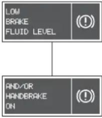 | LOW BRAKE FLUID AND/OR HANDBRAKE ONWhen the ignition key is turned to MAR, the warning light comes on but must go out after a few seconds.The warning light comes on (together with the message + symbol shown on the display) when the level of the brake fluid inside the tank falls below the minimum, due to a possible leak in the circuit and when the handbrake is switch on with the car moving. |
WARNING If the warning light Ⓐ comes on when travelling (together with the message on the display), check that the handbrake is not engaged. If the warning light stays on with the handbrake off (together with the message on the display), stop immediately and contact Alfa Romeo Authorized Services. If the warning light Ⓐ comes on when travelling (together with the message on the display), check that the handbrake is not engaged. If the warning light stays on with the handbrake off (together with the message on the display), stop immediately and contact Alfa Romeo Authorized Services. | ||
 | 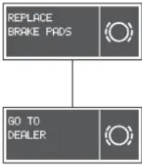 | BRAKE PAD WEARThe warning light on the dial comes on (together with the message + symbol shown on the display) when the front brake pads are worn; in this case, have them replaced as soon as possible.WARNING As the car is fitted with wear sensors for the front brake pads, when replacing them, also check the rear brake pads. |
WARNING
| Warning light | Messageon display | |
| ● | 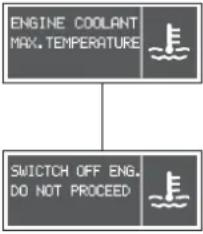 | HIGH ENGINE COOLANT TEMPERATURE WARNINGWhen the engine is very hot, do not remove the tank cap: danger of burns.When the ignition key is turned toMAR, the warning light comes on but must go out after a few seconds.The engine coolant temperature warning light comes on (together with the message + symbol shown on the display) when the engine is overheated.If the warning light comes on, proceed as follows:- Normal driving conditions: stop the car, switch the engine off and check if the water level inside the tank is not below the reference markMIN.In this case, wait a few minutes to let the engine cool down, then open the capslowlyandcarefully, fill with coolant, making sure its level is between reference marksMINandMAXon the tank. Moreover, perform a visual check for any fluid leakage. If the warning light comes on again the next time the engine is started, contact Alfa Romeo Authorized Services.- Car heavy duty(e.g. towing a trailer uphill or car fully loaded): slow down and, if the warning light stays on, stop the car. Pause for 2 or 3 minutes, keeping the engine on and slightly accelerated to facilitate better coolant circulation, then switch the engine off.Check correct fluid level, as described above.WARNINGIn case of highly demanding use of the car, you are recommended to keep the engine on and slightly accelerated for a few minutes before switching it off. WARNINGWhen the engine is very hot, do not remove the tank cap: danger of burns.When the ignition key is turned toMAR, the warning light comes on but must go out after a few seconds.The engine coolant temperature warning light comes on (together with the message + symbol shown on the display) when the engine is overheated.If the warning light comes on, proceed as follows:- Normal driving conditions: stop the car, switch the engine off and check if the water level inside the tank is not below the reference markMIN.In this case, wait a few minutes to let the engine cool down, then open the capslowlyandcarefully, fill with coolant, making sure its level is between reference marksMINandMAXon the tank. Moreover, perform a visual check for any fluid leakage. If the warning light comes on again the next time the engine is started, contact Alfa Romeo Authorized Services.- Car heavy duty(e.g. towing a trailer uphill or car fully loaded): slow down and, if the warning light stays on, stop the car. Pause for 2 or 3 minutes, keeping the engine on and slightly accelerated to facilitate better coolant circulation, then switch the engine off.Check correct fluid level, as described above.WARNINGIn case of highly demanding use of the car, you are recommended to keep the engine on and slightly accelerated for a few minutes before switching it off. |
WARNING
| Warning light | Messageon display |
 | AIR BAG FAILUREWhen the ignition key is turned toMAR, the warning light on the check panel comes on, but must go out after a few seconds. This warning light will come on glowing steadily if there is an operating failure in the Air bag system. WARNINGIf the warning light does not turn on when turning the ignition key to MAR or if it stays on when travelling, this could indicate a failure in safety retaining systems; under this condition air bags or pretensioners could not trigger in the event of collision or, in a restricted number of cases, they could trigger accidentally. Stop the car and contact Alfa Romeo Authorized Services to have the system checked immediately.The failure of the warning light (warning light off) is also indicated by the flashing of the passenger's front Air bag deactivated warning light for more than the normal seconds. WARNINGIf the warning light does not turn on when turning the ignition key to MAR or if it stays on when travelling, this could indicate a failure in safety retaining systems; under this condition air bags or pretensioners could not trigger in the event of collision or, in a restricted number of cases, they could trigger accidentally. Stop the car and contact Alfa Romeo Authorized Services to have the system checked immediately.The failure of the warning light (warning light off) is also indicated by the flashing of the passenger's front Air bag deactivated warning light for more than the normal seconds. |
PASSENGER'S FRONT AIR BAG DEACTIVATEDThe check panel warning light turns on when the passenger's front Air bag is deactivated by means of the relevant key switch. With the passenger's front Air bag activated, turning the ignition key to MAR, the warning light on the check panel comes on but must go out after approx. 4 seconds. WARNINGWarning light indicates also warning light failure. This is indicated by intermittent flashing, over 4 seconds, of warning light In this event, warning light could be not up to indicate restraint system failures, if any. Stop the car and contact Alfa Romeo Authorized Services to have the system checked immediately. WARNINGWarning light indicates also warning light failure. This is indicated by intermittent flashing, over 4 seconds, of warning light In this event, warning light could be not up to indicate restraint system failures, if any. Stop the car and contact Alfa Romeo Authorized Services to have the system checked immediately. |
WARNING
WARNING
| Warning light | Message on display | |
 | 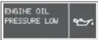 | LOW OIL PRESSUREWhen the ignition key is turned toMAR, the warning light on the check panel comes on but must go out as soon as the engine is started. |
 |  WARNINGIf the warning light ⇌ comes on when travelling (together with the message + symbol shown on the display), switch the engine off immediately and contact Alfa Romeo Authorized Services. WARNINGIf the warning light ⇌ comes on when travelling (together with the message + symbol shown on the display), switch the engine off immediately and contact Alfa Romeo Authorized Services. | |
 | LOW BATTERY CHARGEWhen the ignition key is turned toMAR, the warning light on the check panel comes on, but must go out as soon as the engine is started (a slight delay is permitted when the engine is running at idle). It if stays on, contact Alfa Romeo Authorized Services immediately. | |
| [2265] | SEAT BELTS NOT FASTENEDThe warning light on the check panel will turn on for some seconds when, with the ignition key at MAR, the driver's seat belt is not fastened properly. | |
WARNING
| Warning light | Message on display | |
 | 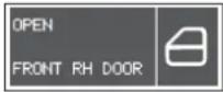 | INCOMPLETE DOOR CLOSINGThe message + symbol shown on the display will appear when one or more doors or the tailgate are not properly shut.The warning light on the dial turns on when one or more doors or the tailgate are not properly shut. This warning light is only fitted on the dials of IMPRESSION versions. |
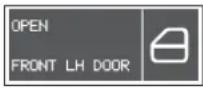 | ||
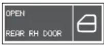 | ||
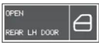 | ||
 | ||
 |  | ENGINE CONTROL SYSTEM (EOBD) FAILUREIn normal conditions, turning the ignition key to MAR, the dial warning light turns on but it should go off when the engine has started. The initial turning on indicates that the warning light is working properly.If the warning light stays on or turns on (together with the message + symbol shown on the display) when travelling: glowing steadily - indicates a fault in the supply/ignition/injection system which could cause high exhaust emissions, possible lack of performance, poor handling and high consumption levels.In these conditions, it is possible to continue driving without however demanding heavy effort or high speeds. Prolonged use of the car with the warning light on may cause damage. Contact an Alfa Romeo Authorized Service as soon as possible.The warning light turns off if the fault disappears, but it is still stored by the system; flashing - indicates that the catalyst could be damaged (see paragraph on “EOBD system” in this chapter).If the warning light flashes, it is necessary to release the accelerator pedal to lower the speed until the warning light stops flashing; continue travelling at moderate speed trying to avoid driving conditions that could cause the warning light to flash again. Contact an Alfa Romeo Authorized Service as soon as possible. If, when turning the ignition key to MAR, the warning light does not switch on or if it turns on glowing steadily or flashing when travelling, contact Alfa Romeo Authorized Service as soon as possible. The operation of the warning light can be checked by traffic agents by proper equipment, therefore comply with the regulations in force in the country where you are driving. If, when turning the ignition key to MAR, the warning light does not switch on or if it turns on glowing steadily or flashing when travelling, contact Alfa Romeo Authorized Service as soon as possible. The operation of the warning light can be checked by traffic agents by proper equipment, therefore comply with the regulations in force in the country where you are driving. |
ENGINE CONTROL SYSTEM (EOBD) FAILURE
| Warning light | Messageon display |
 | ALFA ROMEO CODE SYSTEMWhen the ignition key is turned toMAR, the warning light on the check panel should flash only once and then go out. If the warning light stays on with the key atMAR, this indicates a possible failure: see “Alfa Romeo CODE System”.WARNINGThe turning on at the same time of and warning lights indicates a failure of the Alfa Romeo CODE System.If with the engine running, the warning light flashes, this means that the car is not protected by the engine inhibitor device (see “Alfa Romeo CODE system” in this chapter). Contact Alfa Romeo Authorized Services to have all the keys memorised. |
 POSSIBLE PRESENCE OF ICE ON THE ROADWhen the outside temperature is below or equal to 3°C, in order to warn the driver on the presence of ice on the road, message + symbol are displayed accompanied by the related buzz.The buzz lasts about 2 seconds while the message is displayed for about 10 seconds. After this period, only the symbol is displayed until the temperature does not go over 6°C or until the engine stops.If during travelling, after the presence of ice on the road has been signalled, should temperature rise over 6°C the symbol will go off and should temperature fall again to 3°C, a new message + symbol will be displayed accompanied by the buzz. POSSIBLE PRESENCE OF ICE ON THE ROADWhen the outside temperature is below or equal to 3°C, in order to warn the driver on the presence of ice on the road, message + symbol are displayed accompanied by the related buzz.The buzz lasts about 2 seconds while the message is displayed for about 10 seconds. After this period, only the symbol is displayed until the temperature does not go over 6°C or until the engine stops.If during travelling, after the presence of ice on the road has been signalled, should temperature rise over 6°C the symbol will go off and should temperature fall again to 3°C, a new message + symbol will be displayed accompanied by the buzz. | |
 | GLOW PLUGS (JTD engines)When the ignition key is turned to MAR, the dial warning light comes on and go out when the glow plugs have reached the pre-established temperature.Start the engine as soon as the warning light has gone out.WARNING With a high environment temperature, the warning light may turn on for an imperceptible length of time. For versions/markets where applicable, the warning light flashes for approx. 30 seconds after starting the engine, which means that there is a fault in the glow plug warming system, contact Alfa Romeo Authorized Services. |
 | WATER IN THE FUEL OIL FILTER (JTD engines)The warning light switches on with fixed light when driving, to indicate the presence of water in the fuel oil filter. The presence of water in the fuel circuit may cause serious damage to the entire injection system and cause irregular engine operation. If warning light comes on the dial, contact Alfa Romeo Authorized Services as soon as possible to have the system relieved. Should the above warning indication come one immediately after topping up, water has probably been poured into the tank: turn the engine off immediately and contact Alfa Romeo Authorized Services. The presence of water in the fuel circuit may cause serious damage to the entire injection system and cause irregular engine operation. If warning light comes on the dial, contact Alfa Romeo Authorized Services as soon as possible to have the system relieved. Should the above warning indication come one immediately after topping up, water has probably been poured into the tank: turn the engine off immediately and contact Alfa Romeo Authorized Services. |
| Warning light | Message on display | |
 | ENGINE OIL SENSOR FAILURE (JTD versions)The message + symbol are shown on the display when there is a failure in the engine oil level sensor. Contact Alfa Romeo Authorized Services as soon as possible to have the fault eliminated. | |
 | INERTIAL FUEL CUT-OFF SWITCHThe message + symbol are shown on the display when the fuel cut-off switch comes into operation. | |
 | WARNINGIf, after the message has been displayed, you can smell fuel or notice leaks from the supply system, do not re-engage the switch to avoid the risk of fire. | |
| Warning light | Message on display | |
 |  | INEFFICIENT ABS SYSTEMWhen the ignition key is turned to MAR, the warning light comes on but must go out after a few seconds.This warning light comes on (together with the message + symbol, where required, on the display) when the system is inefficient. In this case, normal braking is ensured, though without making use of the ABS system. Caution is recommended, especially in cases of less than perfect grip. In any case, contact Alfa Romeo Authorized Services as soon as possible. |
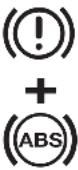 |  | Inefficient EBD electronic braking distributor |
WARNING The vehicle is equipped with an electronic braking distributor (EBD). Simultaneous lighting of dial warning lights (ABD) and (O) (together with the message + symbol on the display) with the engine running indicates an EBD system failure; in this case, any sudden braking action can cause early locking of rear wheels, with possible sideslip. Drive very carefully and go immediately to the nearest Alfa Romeo Authorized Service to have the system checked. The vehicle is equipped with an electronic braking distributor (EBD). Simultaneous lighting of dial warning lights (ABD) and (O) (together with the message + symbol on the display) with the engine running indicates an EBD system failure; in this case, any sudden braking action can cause early locking of rear wheels, with possible sideslip. Drive very carefully and go immediately to the nearest Alfa Romeo Authorized Service to have the system checked. | ||
WARNING
| Warning light | Message on display | |
 | 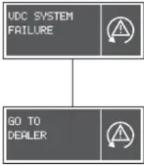 | VDC SYSTEM (VEHICLE DYNAMICS CONTROL)(optional for versions/markets where applicable)When the ignition key is turned to MAR, the dial warning light comes on but must go out after a few seconds.If the warning light does not go out, or if it stays on (together with the message + symbol on the display and the coming on of the ASR button led) when the vehicle is running, contact Alfa Romeo Authorized Services.The flashing of the warning lamp when the vehicle is running indicates the actuation of the VDC system. |
 | OUTSIDE LIGHT FAILUREThe warning light comes on when an anomaly is found in one of the following lights:– sidelights– braking lights or corresponding fuse– rear fog guards– number plate lights.The warning of a fault may mean one or more blown bulbs, a burnt fuse or cut off connection. | |
| [0208] | FUEL RESERVEThe warning light comes on when about 7 litres of fuel are left in the tank, and when the car range is below 50 km. | |
 | REDUCED RANGETHis message is displayed when the car range is below 50 km. | |
 | SPEED LIMIT EXCEEDEDThe message + symbol turns on, together with the sound of the buzzer, on the display when the vehicle exceeds the speed limit set previously (see “Speed limit” in this section). | |
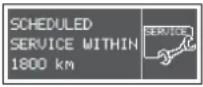 | SCHEDULED MAINTENANCEThis message appears on the display 2,000 kilometres from the deadline given in the Scheduled Maintenance Programme (every 20,000 km) and it is shown again at timed intervals, turning the ignition key to MAR every 200 km. | |
| Warning light | Message on display |
| 贷 | REAR FOG LIGHTSThis warning light comes on when the rear fog lights are turned on. |
| ≠0 | FRONT FOG LIGHTS(optional for versions/markets where applicable)This warning light comes on when the front fog lights are turned on. |
| ← | LEFT-HAND DIRECTION INDICATOR (INTERMITTENT)This warning light comes on when the control lever is moved downwards or, together with right-hand indicator, when the hazard warning lights are switched on. |
| → | RIGHT-HAND DIRECTION INDICATOR (INTERMITTENT)This warning light comes on when the control lever is moved upwards or, together with the left-hand indicator, when the hazard warning lights are switched on. |
| SIDELIGHTS AND DIPPED-BEAM HEADLIGHTSThe warning light on the dial comes on when the sidelights or dipped-beam headlights are switched on. | |
| CONSTANT SPEED ADJUSTMENT (CRUISE CONTROL)(where applicable)The warning light on the check panel turns on, with the knurled ring of the cruise control in the ON position, when the device starts to intervene on the engine. | |
| MAIN-BEAM HEADLIGHTSThe warning light comes on when these lights are turned on. | |
| DIRECTION INDICATORS IF A TRAILER IS TOWEDThe warning light on the dial comes on when the direction indicator control lever is moved up or down, or when the hazard warning light button is pressed. | |
| Warning light on the dial | Message on display |
| SELESPEED GEARBOX FAILURETurning the ignition key to MAR, the warning light on the cluster shall come on and then go off after about 4 seconds. If the warning light stays on, it indicates that a fault has been detected in the Selespeed gearbox; at the same time, the buzzer beeps intermittently for 4 seconds to draw the attention of the driver. Contact Alfa Romeo Authorised Services as soon as possible to remove the fault. | |
| Q-SYSTEM AUTOMATIC GEARBOX FAILURETurning the ignition key to MAR, the warning light on the cluster shall come on and then go off after about 4 seconds. If the warning light stays on or turns on when travelling, it indicates overheated gearbox oil (glowing steadily) or a gearbox fault (flashing).Warning light glowing steadily: it indicates that the gearbox oil has reached the maximum established temperature.To make oil cooling down, stop the car, move the lever to P or N and let the engine idle until the warning light goes out. Resume driving without demanding high performance from the engine. If the warning light comes on again, it is necessary to stop again with the engine idling until it goes out again. If the interval between one lighting up of the warning light and next is below 15 minutes, you are advised to stop the car, turn the engine off and wait for the engine-gearbox unit to cool down completely. Contact Alfa Romeo Authorised Services as soon as possible.Warning light flashing: it indicates a fault in the automatic gearbox.The automatic control system provides an emergency programme. Under these circumstances, you are advised to stop the car and turn the engine off; in fact, the next time the engine is started, the self-diagnostic system could cut off the fault which will however be memorised. Conversely, if the fault remains (warning light flashing), it is necessary to select the gears manually as if driving a car with mechanical gearbox, bearing in mind that the only two speeds available are the 2^nd and 4^th gear. Contact Alfa Romeo Authorised Services as soon as possible. |
CLIMATE CONTROL SYSTEM
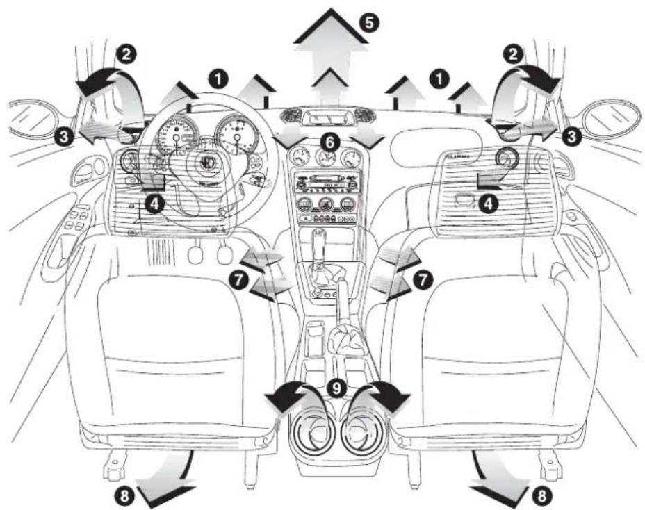
text_image
Diagram of car interior and dashboard layout with numbered components and directional arrows indicating traffic flow or movement.A0A0571m
1 Central defrosting/demisting vents for windscreen - 2 Adjustable upper side vents - 3 Defrosting/demisting vents for side windows - 4 Adjustable side air outlets - 5 Adjustable upper vent - 6 Adjustable centre, swivel vents - 7 Front feet area fixed vents - 8 Rear feet area fixed vents - 9 Rear adjustable swivel outlets.
fig. 94
UPPER VENT ADJUSTMENT (fig. 95)
The vent has an opening/closing control.
● = Completely closed.
j= Completely open.
CENTRE VENT ADJUSTMENT (fig. 96)
Each vent has a lever which makes it possible to direct the flow of air towards the passengers in an horizontal direction. To adjust the air flow, use the opening/closing centre vent device.
● = Completely closed.
= Completely open.
UPPER SIDE VENT ADJUSTMENT (fig. 97)
On the dashboard ends are adjustable vents (A) for car interior, and fixed defrosting/demisting vents (B) for side windows.
Air flow can be adjusted by means of the knob (C).
● = Completely closed.
= Completely open.
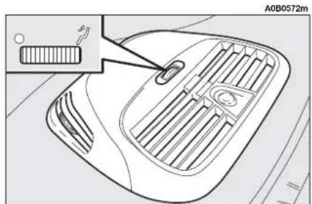
text_image
A0B0572mfig. 95
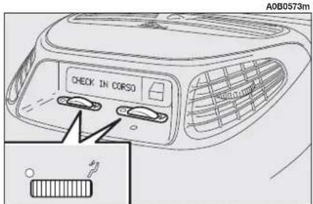
text_image
A0B0573m CHECK IN CORSOfig. 96
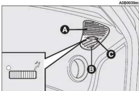
text_image
A0B0039m A B Cfig. 97
REAR SWIVEL OUTLET ADJUSTMENT
Fig. 98: front seats (on dashboard ends)
Fig. 99: rear seat (on the console between seats)
Air flow can be adjusted by means of vanes (A) with press-on opening and closing.
Air flow can be directed by rotating the outlet by means of the vanes.
MANUAL CLIMATE CONTROL SYSTEM (fig. 99a - where applicable)
CONTROLS
1 Air temperature adjustment knob (mixing warm / cold air)
2 Climate control compressor on / off button
3 Inside air re-circulation on / off button
4 Fan knob
5 Maximum defrosting / demisting on / off button for windscreen and front side windows and wing mirror coils
6 Rearscreen heating and wing mirror defrosting on / off button.
7 Air distribution knob.
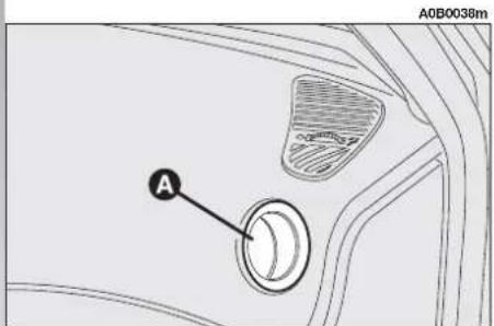
text_image
A0B0038m Afig. 98

text_image
A0B0289m Afig. 99
HEATING
To obtain the temperature required, proceed as follows:
— turn knob (1) as far as it will go clockwise
— turn knob (4) clockwise to the required speed;
— urn knob (7) to set air distribution as follows:
to warm feet and to demist the windscreen
to warm feet and to keep the face cool (bilevel function)
to direct warm air to the front and rear lower parts of the passenger compartment.
→ for summer ventilation
↑ to defrost/demist the windscreen
— turn off inside air re-circulation (if on).
QUICK FRONT WINDOW DEMISTING / DEFROSTING (MAX-DEF FUNCTION)
Press button (5) ☐ to quicken demisting / defrosting of the windscreen and front side windows (MAX-DEF function).
Max. quick demisting / defrosting function will be activated.
When this function is on the relevant button led will come on.
To turn this function off, press button (5) #again (the button led will go off) or turn whatever knob or press any manual climate control system button.
After demisting/defrosting, turn the MAX-DEF function off to maintain the optimum conditions of vision.

text_image
1 TEMP 4 OFF MODE 2 3 5 6 A0B0598mfig. 99a
Preventive demisting procedure
In cases of heavy damp and/or rain and/or big differences in temperature between inside the car and outside, it is advisable to proceed as follows to demist the windows:
— turn off inside air re-circulation (if on)
— turn knob (1) as far as it will go clockwise
— turn knob (4) clockwise to an intermediate speed
— turn knob (7) to ↑ or ↑ ↓ if the windows do not mist up.
Climate control system is very useful to speed up demisting. Set controls to demisting function as described previously and switch the climate control system on by pressing button (2)
REARSCREEN AND WING MIRROR (where applicable) DEMISTING / DEFROSTING
Press button (6) ☐ to demist /defrost the rearscreen and wing mirrors (where applicable).
When this function is on the relevant button led will come on.
To turn this function off, press the button again, the button led will go off.
WARNING Do not apply stickers on the inside of the rearscreen over the heating filaments to avoid damaging it.
FAN SPEED ADJUSTMENT
To ventilate the passenger's compartment properly, proceed as follows:
— open completely the central and side vents;
- turn knob (4) to the required speed;
- turn knob (7) to →;
-- turn off inside air re-circulation (if on).
SWITCHING THE INSIDE AIR RE-CIRCULATION FUNCTION ON
Press button (3) ⬆ to turn the inside air re-circulation function on.
When this function is on the relevant button led will come on.
It is advisable to turn on the inside air recirculation function in queues or tunnels to avoid admitting polluted air from outside.
The prolonged use of this function should however be avoided, especially with several persons on board, to avoid the possibility of the windows misting inside.
WARNING The inside air re-circulation function makes it possible to reach the required "heating" or "cooling" conditions faster.
It is however inadvisable to use it on rainy/cold days as it would considerably increase the possibility of the windows misting inside, especially if the climate control system is off.
CLIMATE CONTROL (COOLING)
Proceed as follows:
— turn knob (1) as far as it will go counterclockwise (blue led next to TEMP lit);
— turn knob (4) to the required speed;
- turn knob (7) to →;
— press buttons (2) ⚙ and (3) ⬇ the relevant leds will go on.
Cooling adjustment
Proceed as follows:
— turn off inside air re-circulation (if on);
— turn knob (1) counterclockwise to reduce temperature;
— turn knob (4) counterclockwise to reduce the fan speed.
LOOKING AFTER THE SYSTEM
During the winter the climate control system must be turned on at least once a month for about minutes.
Before summer, have the system checked at Alfa Romeo Authorized Service.
AUTOMATIC TWO-ZONE CLIMATE CONTROL SYSTEM
To start the system (fig. 100):
— turn the knob rings to set the required temperatures (driver's side — passenger's side).
— press the AUTO button.
WARNING The climate control system makes it possible to adjust the temperatures required for the two sides with a maximum difference of 7^ C between the driver's and the passenger's sides.
WARNING The climate control compressor works only when the engine is running and the outside temperature is more than 2°C.

WARNING
The climate control compressor cannot work when
the outside temperature is less than 2^ C. Therefore, it is recommended that the internal air recirculation function is not used when the outside temperature is low, as the windows could mist over rapidly.
For more detailed information on the system and how to make the best use of it, read the instructions given in the following pages.

The coolant used for the climate control system is R134a which meets current regulations and does not harm the environment in the event of accidental spillage.
Absolutely avoid the use of other fluids which are incompatible with the system components.

text_image
A0B0382m 25.5 °C AUTO MODE 22.5 °C Afig. 100
GENERAL
The car is equipped with a two-zone climate control system, controlled by an electronic control unit which makes it possible to separately adjust the air temperature on the driver's side and on the passenger's side. To obtain optimum temperature control in the two areas of the passenger compartment, the system has an outside sensor, a passenger compartment sensor and a two-zone sun ray sensor.
On some versions, the system is integrated with an incipient misting sensor installed behind the internal rearview mirror, which is able to "monitor" a predefined area of the windscreen inner surface which can automatically act on the system to prevent or reduce misting, through a series of operations such as: opening air recirculation, enabling compressor, air flow to the windscreen, fan speed sufficient for demisting; and, in case of heavy misting, enabling the MAX-DEF function.

To ensure correct operation of the incipient misting sensor, stickers (e.g. road licence holder) must not be applied in the "control" area between the sensor and the windscreen. For this very reason, both the sensor and the windscreen must always be kept clean, to avoid accumulation of dirt or other substances.
WARNING The demisting procedure is enabled every time the ignition key is turned to MAR, or pressing the AUTO button. When this procedure is working it can be turned off pressing one of the following buttons: compressor, air recirculation, air distribution, air flow. This operation inhibits the incipient misting sensor signal until the AUTO button is pressed again or the next time the ignition key is turned to MAR.
On certain versions, the system is integrated by an anti-pollution sensor that is able to switch on the inside air recirculation function automatically, to reduce the unpleasant smell of polluted air when driving in urban areas, queues, tunnels, and when the windscreen wash/wiper is operated (with the typical smell of spirits).
WARNING The function of the anti-pollution sensor is subordinate to safety conditions; therefore disabling the climate control compressor or at an outside temperature below 4°C, the sensor is disabled. In any case, the sensor can be re-enabled pressing the recirculation button until taking it to the automatic mode.

The anti-pollution sensor is placed in the air flow in front of the combined particle activated carbon filter and, therefore, must be protected against possible compressed air jets produced by cleaning equipment. Moreover, the water collected from the windscreen wipers should not come into contact with the sensor: otherwise, the internal air recirculation function could be disabled for long periods.
The air quality control is also entrusted to a combined particle and activated carbon filter.
The climate control system automatically controls and adjusts the following parameters and functions:
— temperature of the air admitted to the passenger compartment (for the driver's and passenger's side separately)
— fan speed
— air distribution
— inside air recirculation on/off
— climate control compressor on/off enable.
The settings of the following functions can be modified manually:
— fan speed
— air distribution
— inside air recirculation on/off
— climate control compressor on/off enable
— window defrosting/demisting.
The control of the functions that have not been modified manually will always be automatic and, in any case, the temperature of the air flowing into the passenger compartment is controlled automatically depending on the temperatures set on the driver's and passenger's displays.
WARNING Manual selections prevail over automatic ones and remain in storage until the user decides to resume automatic control. The settings selected manually are stored when the engine is switched off and resumed the next time the engine is started.
CONTROLS (fig. 101)
1 - Inside temperature adjustment knob (driver's side)
2 - Inside temperature set display (driver's side)
3 - Knob for adjusting the fan speed and switching the system off
4 - Fan speed set, air distribution and system off display (OFF)
5 - Inside temperature set display (passenger's side)
6 - Inside temperature adjustment knob (passenger's side)
7 - Inside air recirculation on/off button (manual/automatic)
8 - Air distribution selection button
9 - Rearscreen heating and wing mirror defrosting on/off button 📄
10 - Maximum defrosting/demisting on/off button for windscreen and front side windows, rearscreen heating and wing mirror coils (function MAX-DEF - 📋)
11 - Button for aligning the temperature set on the passenger's side with that on the driver's side MONO
12 - Climate control compressor on/off enable button
13 - Inside air temperature sensor
14 - Button for selecting the system automatic mode AUTO

text_image
A0B0056m 1 2 3 4 5 6 AUTOfig. 101
HOW TO USE THE AUTOMATIC TWO-ZONE CLIMATE CONTROL (fig. 101)
WARNING The knob rings are not provided with automatic stopper; therefore, they are free to rotate in both directions once they have reached the maximum or minimum values.
The system can be started in different ways, but it is recommended that the required temperatures are set on the
displays; then, press (14) AUTO button.
Thus, the system will start operating fully automatic, to reach the set temperatures in the shortest possible time and keep them.
During the fully automatic operation of the system, the set temperatures can however be modified at any time: the system will automatically modify its own settings to adapt itself to the new requirements.
WARNING The temperature difference between the driver's and the passenger's sides must not be greater than 7°C in order to be accepted by the system.
The selections made by the system in automatic mode can be customized by manually acting on the following controls:
— fan speed adjustment knob (3)
— air distribution selection button (8)
— inside air recirculation on/off button (7)
- climate control compressor on enable button (12) ⚙️.

Manually selecting one or more of these functions turns off the right led on the button (14) AUTO.
With one or more functions switched on manually, the temperature control for the air admitted to the passenger compartment will in any case continue to be monitored automatically by the system (left led on button 14 AUTO on), except with the climate control compressor off.
In fact, in this condition, the temperature of the air admitted into the passenger compartment cannot be lower than the outside air temperature; this condition is indicated by the turning off of the two leds on button (14) AUTO and flashing on the display (2) and/or (5) related with the temperature rate that cannot be obtained.
AIR TEMPERATURE ADJUSTMENT KNOBS (fig. 102)
Turning the rings of knobs (1 or 6) clockwise or counterclockwise, respectively higher or lowers the temperature of the air required in the left zone (knob 1) or right zone (knob 6) of the passenger compartment. The temperatures set are shown on the displays (2) and (5) placed below the respective knobs.
Separate operation of the temperatures set is restored automatically using knob (6) is actuated.
Turning the knob rings clockwise or counterclockwise, until they reach the extreme selection positions HI or LO, will cause the maximum heating or cooling functions, respectively, to be switched on:
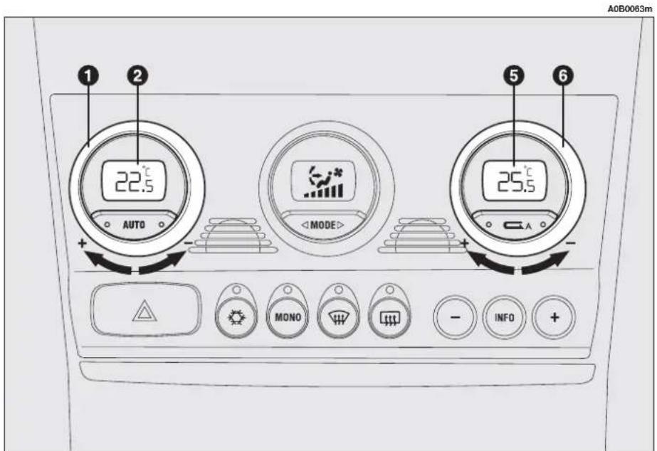
text_image
A0B0063m 1 2 22.5 °C AUTO + - MODE 5 6 25.5 °C A + - MONO INFO + - +fig. 102
HI function (highest heating power - fig. 103)
It is switched on by setting a temperature of more than 32.5°C on the display, and can be switched on independently from the driver's or passenger's side, or both of them; this setting brings the system to the "one-zone" mode and is shown by both displays.
This functions can be switched on when you wish to heat the passenger compartment as quickly as possible, by taking the greatest advantage from the system potential.
The function uses the maximum temperature of the heating fluid, whereas air distribution to feet and 5 ^th fan speed.
With the function switched on, however, all the manual settings can be made.
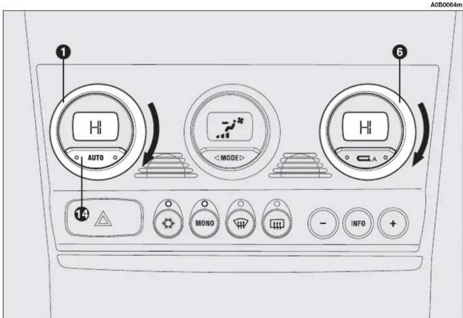
text_image
A0B0064m 1 AUTO 6fig. 103
To switch the function off, you only need to turn the ring of a knob (1) or (6) of the temperature set to a value lower than 32.5°C; the opposite display will show 32.5°C.
By pressing button (14) AUTO, the display indicates a temperature of 32.5°C and falls within an operating condition with automatic temperature control.
LO function
(highest cooling power - fig. 104)
It is switched on by setting a temperature lower than 16.5°C on the display; this setting is shown by both displays.
This function can be switched on when you wish to cool the passenger compartment as quickly as possible, by taking the greatest advantage from the system potential.
The function cuts off air heating, switches on both internal air recirculation (to prevent hot air from entering the compartment) and the climate control compressor, brings air distribution to and 5 ^th fan speed.
With the function switched on, however, all the manual settings can be made.
To switch the function off, you only need to turn the ring of a knob (1) or (6) of the temperature set to a value greater than 16.5°C; the opposite display will show 16.5°C.

text_image
A0B0065m 1 LO AUTO 6 LO MODE 14 MONO - INFO +fig. 104
By pressing button (14) AUTO the display indicates a temperature of 16.5^ C and falls within an operating condition with automatic temperature control.
MONO BUTTON FOR ALIGNMENT OF THE TEMPERATURES SET (fig. 105)
By pressing button (11) MONO the passenger's side temperature automatically aligns with that on the driver's side and, therefore, the same temperature can be set for both areas by simply turning the ring of knob (1), on driver's side.
This function is provided to facilitate temperature adjustment inside the entire passenger compartment when only the driver is on board.
Separate operation of set temperatures is automatically restored when the passenger operates the ring of knob (6) or by pressing button (11) MONO.

text_image
A0B0066m 1 22.5°C AUTO MODE 22.5°C A 6 MONO - INFO + 11fig. 105
FAN SPEED ADJUSTMENT KNOB (fig. 106-107)
Turning the ring of knob (3), clockwise or counterclockwise will cause the fan speed - and, therefore, the amount of air flowing into the passenger compartment - to increase or decrease, respectively; the 16 speeds that can be selected are displayed by a bar (every 3 clicks), up to a maximum of 6 illuminated bars:
The fan can be cut off (all bars off) only if the climate control compressor has been switched off by pressing button (12). To resume automatic fan speed control after a manual setting has been made, press button (14) AUTO. By fully turning the ring of knob (3) counterclockwise, the system will be turned off, with the following situation: display (2) OFF; display (5) OFF; central display (4) OFF and left-hand led available on internal air recirculation button (7). ON and both led on AUTO button switch OFF.
A0B0067m
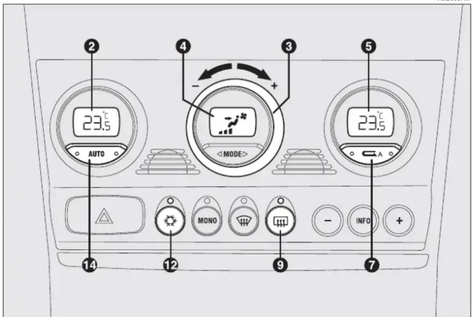
text_image
23.5 AUTO 4 - + - MODE> 23.5 A 14 12 MONO 9 - INFO 7fig. 106
WARNING By pressing the internal air recirculation button (7), it is possible to let external fresh air into the passenger compartment.
To turn the system on again, you only need to turn the ring of knob (3) clockwise, or press any button, except the internal air recirculation button (7) and rear window heater button (9); this operation resumes all the operating conditions previously stored in the memory.
WARNING After exiting the condition OFF, the internal air recirculation is resumed to the condition preceding the switching off.

text_image
A0B0068m 2 AUTO 4fig. 107
AIR DISTRIBUTION SELECTION BUTTON (fig. 108)
By pressing button MODE (8) repeatedly, you can manually choose one of the five possible modes for air distribution:
→ Flow of air to the dashboard centre and side outlets and rear outlets.
Splitting of the air flow between the vents to the lower part of the passenger compartment (warmest air) and the dashboard centre and side outlets and the rear outlet (coolest air). This air flow distribution is particularly useful in spring and autumn, when the sun is shining.
Air flow towards the front and rear lower part of the passenger compartment. Due to the natural tendency of heat to spread upwards, this type of distribution allows heating of the passenger compartment in the shortest time, also giving a prompt feeling of warmth to the coldest parts of the body.

text_image
A0B0069m 22.5°C AUTO 3fig. 108
↑ Splitting of the air flow between the
down windscreen and side window defrosting/demisting vents and the lower part of the passenger compartment. This type of air distribution allows satisfactory heating of the passenger compartment while preventing possible misting of the windows.
Air flow to the windscreen and front side window vents to demist or defrost them.
To resume automatic air distribution control after a manual selection, press button (14) AUTO.
CLIMATE CONTROL COMPRESSOR ON/OFF ENABLE BUTTON (fig. 109)
Pressing button (12) ☑ enables the turning on of the climate control compressor. This condition is shown by the lighting up of the led placed on the button itself.
When the climate control compressor is turned off, the leds on buttons (14) AUTO and (12) go off; automatic inside air recirculation control is also excluded (both leds off on button 7) which always stays off to prevent window misting; in any case, the automatic operation of inside air recirculation can be resumed (though it is not recommended) by pressing button 7.
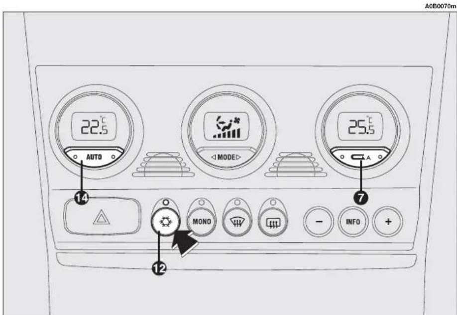
text_image
A0B0070m 22.5 °C AUTO MODE 25.5 °C A 14 MONO INFO + 12fig. 109
When the climate control compressor is off, it is not possible to admit air to the passenger compartment with a temperature below the outside temperature; in this case, the value flashes on the display concerning the temperature that cannot be reached and the left led on button (14 AUTO - fig. 110) goes off.
The switching off of the climate control compressor remains in storage even when the engine has been stopped. To resume automatic control for switching on the climate control compressor, press button (12) again, the button led will turn on, or press button (14) AUTO; in which case, the other manual settings set will be cancelled.

WARNING
Operation of the climate control compressor is necessary for cooling and dehumidifying the air; it is advisable to keep this function always on, to prevent window misting problems.

text_image
A0B0071m 22.5 AUTOfig. 110
INSIDE AIR RECIRCULATION ON/OFF BUTTON
(fig. 111)
Inside air recirculation is controlled according to three operating logics:
— automatic control, indicated by the turning on of the right led on the button;
- forced switching on (inside air recirculation always on), indicated by the turning on of the left led on the button (and by the right led going off at the same time);
— forced switching off (inside air recirculation always off, with air inlet from the outside), indicated by the turning off of both leds.
These operating conditions are obtained by pressing in sequence the inside air recirculation button (7).
When inside air recirculation is controlled automatically by the system, the right led on the air recirculation button (7) C stays on all the time and the left led shows the air recirculation condition:
ON = air recirculation operating;
OFF = air recirculation off.
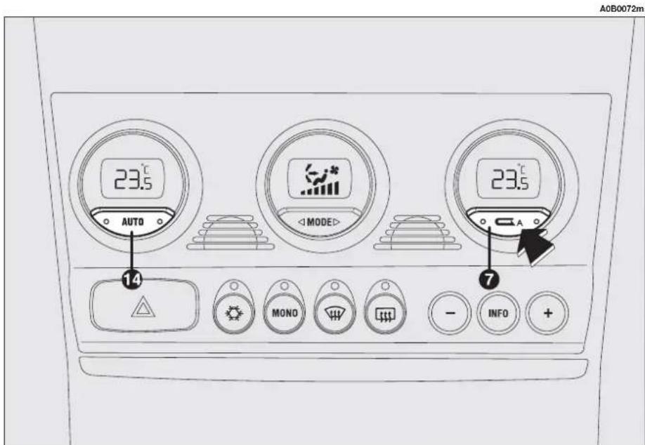
text_image
A0B0072m 23.5 °C AUTO 14 MONO INFO 7 23.5 °C MODEfig. 111
If inside air recirculation has been switched on or off manually, the led on button (14) AUTO turns off.
In automatic operation, inside air recirculation is switched on automatically when the anti-pollution sensor detects the presence of polluted air, for instance in cities, queues, tunnels, and when the windscreen wash/wiper is operated (with the characteristic smell of spirit).

WARNING
With the outside temperature below 2°C the climate control compressor is unable to work. It is therefore inadvisable to use the inside air recirculation function with low outside temperature as windows may mist over quickly.

WARNING
The inside air recirculation function makes it possible
to reach the required "heating" or "cooling" conditions faster. It is however inadvisable to use it on rainy/cold days as it would considerably increase the possibility of the windows misting inside, especially if the climate control system is off.

WARNING
In certain weather conditions (e.g. outside temper-
ature around 0°C) and with automatic air recirculation control on, mist may form on the windows. In this case press the inside air recirculation button (7), to switch off recirculation (leds on button off) and if necessary increase the flow of air to the windscreen.

WARNING
It is advisable to turn on the inside air recirculation sys-
tem in queues or tunnels to avoid admitting polluted air from outside. The prolonged use of this function should however be avoided, especially with several persons on board, to avoid the possibility of the windows misting inside.
BUTTON AUTO AUTOMATIC OPERATION (fig. 112)
When button (14) AUTO is pressed, the system automatically regulates the amount and distribution of the air admitted into the passenger compartment, clearing all the previous manual settings.
This condition is indicated by the lighting of both button leds.
When the right led, on button (14) AUTO, is OFF, it indicates that one or several manual operations have been carried out and, therefore, that automatic control is not complete (except for temperature control, which is always automatic) indicated by the left led on.
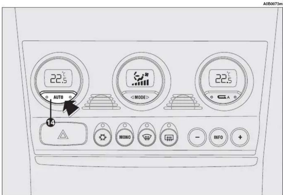
text_image
A0B0073m 22.5 °C AUTO 14 < MODE > 22.5 °C ○ A MONO - INFO + +fig. 112
QUICK FRONT WINDOW DEMISTING/DEFROSTING BUTTON (MAX-DEF function) (fig. 113)
Pressing button (10) the climate control automatically activates timed operation of all the functions needed to quicken demisting/defrosting of the windscreen and front side windows, i.e.:
— it turns on the climate control compressor;
— switches off inside air recirculation, if on (both leds off);
— sets the maximum air temperature (HI) on both displays (2) and (5);
— operates the fan at a predefined speed;
— directs the flow of air towards the wind-screen and front side window vents;
— turns on rearscreen heating and, if present, the wing mirror coils.
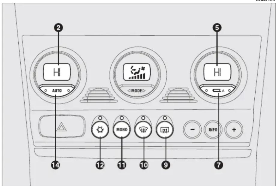
text_image
2 AUTO 5 MODE 14 12 MONO 11 10 9 - INFO + 7fig. 113
When the maximum demisting/defrosting function is on, the led on button (10) 📊, the led on the rearscreen heating button (9) 📊 and the led on button (12) ✿ come on; at the same time the leds on button (7) ⬇ go out.
WARNING If the engine is not warm enough, the function will not engage the predefined fan speed immediately, to limit the flow to the passenger compartment of air that is not warm enough to demist the windows.
When the maximum demisting/defrosting function is on, the only manual operations possible are manual adjustment of the fan and switching rearscreen heating off.
Pressing one of the following buttons: (10) 🎨, (7) 📁, (11) MONO, (14) AUTO or (12) ⚙ the system switches off the maximum demisting/defrosting function, resuming the system operating conditions prior to turning it on, in addition to activating the last function required, if any.
WING MIRROR AND REARSCREEN DEFROSTING/ DEMISTING BUTTON (fig. 114)
Pressing button (9) [t], turns on demisting/defrosting of the rearscreen and, if present, the wing mirror coils.
The activation of this function is shown by the turning on of the led on the button.
This function is timed and switches off automatically after 20 minutes, or pressing the button again; the function is also switched off when the engine is stopped and will not be switched on again the next time the engine is started.

text_image
A0B0075m 23.5 AUTO MODE 23.5 - INFO + 9fig. 114
WARNING Rear heated window manual on/off control prevails over automatic activation decided by the climate control system control unit.
This function is timed and switches off automatically after 20 minutes, or pressing the button again; the function is also switched off when the engine is stopped and will not be switched on again the next time the engine is started.
WARNING The system turns on rearscreen heating automatically if the temperature is below 3°C.
WARNING Do not apply stickers on the inside of the rearscreen over the heating filaments to avoid damage that might cause it to stop working properly.
WARNING When reconnecting the negative battery cable after having disconnected it, wait for 2 minutes before turning the key to enable the climate control system to reset actuator strokes properly.
POLLEN FILTER
This filter has the specific capability of combining the mechanical filtering of the air with an electrostatic effect so that the outside air admitted to the passenger compartment is purified and free from particles such as dust, pollen, etc.
In addition to the above, it also effectively reduces the concentration of pollutants.
The filtering action takes place under all air inlet conditions and it is clearly most effective with the windows shut.
Have the conditions of the filter checked by Alfa Romeo Authorized Services at least once a year, preferably on the onset of summer.
If the vehicle is used mainly in polluted or dusty areas it should be checked and if necessary replaced, at shorter intervals.

Failure to replace the filter may considerably reduce the effectiveness of
the climate control system up to blocking the air flow from the outlets and vents.
ADDITIONAL HEATER (JTD engines) (for versions/markets where applicable)
The car is equipped with an additional heater (not programmable) which supports the engine during cold or winter weather to quickly reach a comfortable temperature inside the passenger compartment.
The heater operates with the engine running when the outside temperature is below 20^ C and the engine has not yet reached normal operating temperature.
CONTROLS
TAILGATE OPENING (fig. 115)
To open the boot pull the lever (A) at the side of the driver's seat.

text_image
WARNING Do not operate the boot re- lease lever with the car on the move.HAZARD WARNING LIGHTS (fig. 116)
They are switched on by pressing button (A), regardless of the position of the ignition key.
When the hazard warning lights are switched on, the switch itself begins to flash together with the direction indicator warning lights and the emergency indicator on the instrument panel. This functions is switched off by pressing the button again.

text_image
A A0B0042mfig. 115

text_image
WARNING Use of the hazard warning lights is ruled by the High- way Code of the country in which the car is used. Observe regula- tions.
text_image
A0B0036m 20.5° ↓ AUTO ↓ MODE ↓ AUTO ↓ MODEfig. 116
FRONT FOGLIGHTS (fig. 117) (where required)
These come on when button (A) is pressed and when the external lights are already on.
The warning light ≠D will light up on the instrument panel.
By turning the ignition key to STOP, the fog lights are turned off automatically and do not come on the next time the engine is started without pressing button (A).
Press the button (A) again to switch the front foglights off.
WARNING The front foglights should be used in compliance with the local traffic laws.
REAR FOG GUARDS (fig. 117)
These are turned on, with the dipped beam headlamps or fog lights on, by pressing button (B).
At the same time, warning light Ⓧ on the instrument cluster lights up.
By turning the ignition key to STOP, the fog guards are automatically turned off and they do not come on the next time the engine is started unless button (B) is pressed.
Press button (B) to turn them off.
WARNING Always use the rear fog guards in accordance with local regulations in force.
DASHBOARD LIGHTING ADJUSTMENT (fig. 118)
When the outside lights are on, the dashboard lighting is adjusted by pressing button (A).
Each press of the button (A) cyclically selects one of the three lighting levels provided: low-medium-high.
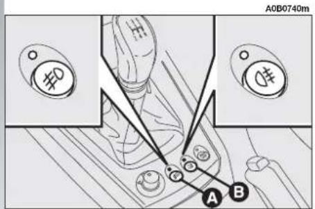
text_image
A0B0740m #D # A Bfig. 117

text_image
A0B0325m Afig. 118
INERTIAL FUEL CUT-OFF SWITCH (fig. 119)
This is an automatic safety switch which is triggered in the event of crash to interrupt the flow of fuel.
The intervention of the inertial switch is indicated by a message + symbol on the Infocenter display (see "Infocenter Display" in this chapter) and by the door unlocking.

WARNING
If a smell of fuel is noted following an accident, or
the fuel system is leaking, to avoid the risk of fire do not reset the switch.
Inspect the care carefully to make sure that there are no fuel leaks, for instance in the engine compartment, under the vehicle or near the tank area.
If no leaks are found and the vehicle can be restarted again, press button (A) to activate the fuel supply system.
After a collision, remember to turn the ignition key to STOP so as not to run the battery down.
OPENING THE FUEL FLAP (fig. 120)
The fuel flap is released from inside the car raising the front part of the lever (A).

text_image
A0B0574m Afig. 119

text_image
A0B0044m Afig. 120
HEADLIGHT CORRECTOR (fig. 121)
If the car is fitted with xenon headlights, beam aiming is electronic and therefore control (A) on the mask near the steering column is not present.
The headlights should be aimed correctly depending on the vehicle load.
The control (A) on the plate at the side of the steering column can be moved to four positions corresponding to the vehicle loads given below:
position 0: 1 or 2 people occupying front seats, full fuel tank, on-board equipment present;
position 1: 5 people on-board;
position 2: 5 people on-board, luggage compartment full (50 kg approximately); position 3: Driver and 300 kg in luggage compartment.

WARNING Check the positioning of the headlight beams every you change the load to be car-
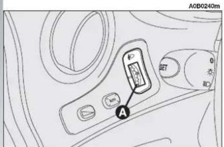
text_image
A0B0240m Afig. 121
HAND BRAKE (fig. 122)
The hand brake lever is located between the two front seats.
To operate the brake when the vehicle is "stationary", pull the lever (A) upwards until the required braking action is obtained.
When the ignition key is in the MARposition, the Ⓓ warning light will come on on the instrument panel.

text_image
A0B0288m A Bfig. 122

WARNING
The wheels should be locked after a few clicks of the hand brake. If this does not occur, contact Alfa Romeo Authorized Services to have the hand brake adjusted.
To release the hand brake:
— slightly lift the lever (A) and press the release button (B);
— holding the button down lower the lever. The Ⓔ warning light on the instrument panel will go out.
To prevent the car from moving accidentally, keep the brake pedal pressed when engaging the handbrake.
WARNING The handbrake lever (A) is fitted with a safety device which prevents the brake from being released when, if the lever is pulled, button (B) is pressed. Therefore, to release the brake, in addition to pressing button (B), it is also necessary to pull lever (A) further upwards to release the safety device, then lower the lever completely
GEARSHIFT LEVER (fig. 123)
Depending on the versions the car is fitted with a five or six speed mechanical gearbox (see "Technical specifications" chapter).
The position of the individual gears is shown by the pictogram on the gearshift lever knob.
When changing gear, always fully depress the clutch pedal. Before engaging reverse gear (R) wait for the car to be stationary.
A0B0290m

text_image
1 3 5 2 4 R 1 3 5 2 4 6 Rfig. 123
For 2.5 V6 24V versions and Diesel versions, to engage reverse gear (R), it is necessary to wait for the car to be stationary, then raise the ring under the grip (with the fingers of the same hand holding the lever).
After engaging reverse gear, release the ring. It is not necessary to raise the ring on the lever when shifting from reverse to another gear.
WARNING Reverse gear can only be engaged with the vehicle completely stopped. With the engine running, before engaging reverse gear it is necessary to wait for at least 3 seconds with the clutch pedal fully pressed, to avoid grating and the possibility of damaging the gears.

Do not drive with your hand resting on the gearshift lever, since the pressure, though slight, with the passing of time, the parts inside the gear.

WARNING
To change gear smoothly, the clutch pedal must be
fully depressed. Therefore, there should be no hindrances under the pedal unit. Make sure that any mats are well laid and do not interfere with the pedals.
SELESPEED GEARBOX (optional for versions/markets where applicable)
The 2.0 JTS engine can be supplied with a mechanical gearbox with electronic control, called "Selespeed".
The Selespeed considerably simplifies the use of the car, it reduces driving fatigue in town or when frequent gearshifting is necessary, but at the same time it assures brilliant performance.
WARNING To be able to use the Selespeed correctly, this chapter should be read in full to understand the correct, permissible operations to be carried out right from the start.
This device comprises a conventional mechanical gearbox to which an electronically-operated electro-hydraulic device has been added which automatically controls the clutch and gear engagement.
The clutch pedal has been eliminated and the vehicle moves off using only the accelerator pedal.
Gearshifting takes place through a floating control lever (A-fig. 124) with only one stable central position. Using this lever it is possible to request increase/decrease of the ratio of the gear engaged and/or engagement of reverse gear (R) or neutral (N).
There are also two levers on the steering wheel spokes (fig. 125) through which, only with the car on the move (with speed above 0.5km / h ), it is possible to shift gear up or down.
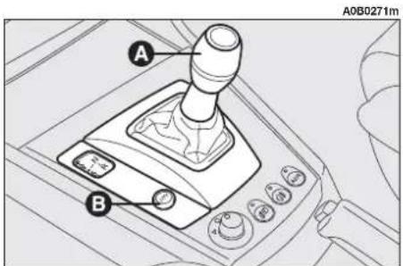
text_image
A B A0B0271mfig. 124

text_image
A0B0270mfig. 125
The gearbox can work in two operating modes:
— the first is semiautomatic (then called MANUAL), in which the driver directly requests gearshifting through the lever on the centre console or pressing the buttons at the steering wheel;
— the second is automatic, called CITY (mode selectable with the specific button B-fig. 124, the CITY sign appears on the display fig. 126 fitted on rev-counter), in which the system decides directly when to shift gear.
With the gearbox in the CITY mode it is still possible to carry out manual gearshifting, both using the gear lever and the steering wheel controls. The gearbox remains in the CITY mode.
The gear engaged (fig. 126) is always signalled on the display regardless of the selected mode.
N = neutral;
1 = first gear;
2 = second gear;
3 = third gear;
4 = fourth gear;
5 = fifth gear;
R = reverse.
Failures of Selespeed gearbox are signalled to the driver through a warning light (B-fig. 126) accompanied by an acoustic signal.
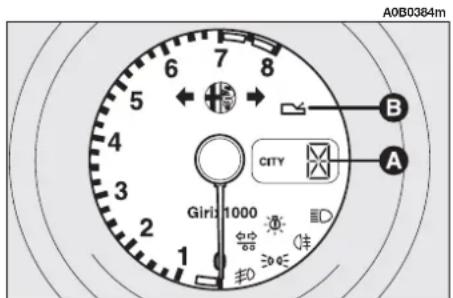
text_image
A0B0384m 6 7 8 5 4 3 2 1 Girl 1000 CITY A ±0.05 ±0.05 ±0.05 ±0.05fig. 126
SYSTEM ACTIVATION
WARNING Opening the driver's door, the Selespeed starts the hydraulic part of the system to prepare it for the engine to be started. This function (noted by the turning of the electric pump) is deactivated after 10 openings/closings of the door that are not followed by actual system activation using the ignition key.
Turning the ignition key to MAR, all the segments of the display (A-fig. 126), the gearbox failure warning light (B-fig. 126) and the word CITYlight up. After about one second, the display indicates the gear engaged (N, 1, 2, 3, 4, 5, R); from this moment, the Selespeed system accepts gearshift commands.
WARNING If after 10 seconds the display segment do not display the gear engaged or the failure warning light stays on, turn the ignition key to STOP and wait for the display to go off, then repeat the system activation procedure. If the fault persists, contact Alfa Romeo Authorized Services
WARNING Before operating the gear-shift control lever, always check the gear engaged on the display (N, 1, 2, 3, 4, 5, R).
When the engine is off and the vehicle is stationary, it is possible to engage all the gears.
With the vehicle stationary and with the brake pedal pressed, requests to shift gear are accepted only if they are carried out through the control lever on the central console.
To request gearshifting, in addition to keeping the brake pedal pressed it is necessary to:
— to increase gear (+) (fig. 127) push the lever "forwards" (if the car is in first gear this shifts to second, if it is in second gear it goes to third and so on up to fifth). If the system is in neutral (N) or reverse (R) the forward movement on the lever causes engagement of first gear (1).
— to shift down (—) (fig. 127) push the lever backwards (if the car is in fifth gear it moves to fourth, if fourth gear is engaged it shifts to third and so on down to first).
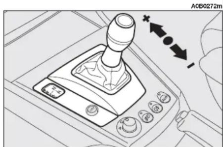
natural_image
Interior view of a car gear shift lever with control buttons and directional arrows (no text or symbols)fig. 127
To put the gearbox in neutral (N), starting from the condition with the vehicle stationary and the brake pedal pressed, it is necessary to move the gearshift control lever to the right (fig. 128).
From any gear (N, 1, 2, 3, 4, 5) and with the vehicle practically at a standstill, it is possible to request engagement of reverse gear, pushing the lever to the right and then backwards (fig. 129). If the vehicle is on the move, the request is not accepted; wait for the car to stop and then request reverse gear engagement again
WARNING Once a gear has been shifted it is necessary to release the gearshift control lever immediately after making the request. A prolonged action (over 10 seconds) causes automatic shifting to CITY; previous conditions are restored when releasing the lever.
WARNING If wanting to leave the car parked on a sloping road with a gear engaged to keep it braked, it is necessary to check that the Infocenter display shows the new gear engaged and then wait for 1 to 2 seconds before releasing the brake pedal to allow complete clutch engagement.

natural_image
Mechanical gear shift lever diagram showing keyway and control buttons (no text or symbols)fig. 128

text_image
A0B0274m N Rfig. 129
STARTING THE ENGINE
The engine can be started with the gear engaged or in neutral (N), provided that the brake pedal is pressed down.
WARNING Keep the brake pedal pressed during the starting operation. As the brake pedal stiffens if it is pressed repeatedly with the engine off, in this situation, to allow the engine to be started, it is necessary to increase the pressure exerted on the pedal itself.
After starting, the gearbox automatically sets to neutral, the display shows the letter (N) and the system selects the operating mode stored before switching off.

WARNING
If the engine fails to start with the gear engaged, the driver is alerted of the potentially dangerous situation due to the fact that the gearbox has automatically set to neutral by the buzzer and the display on the rev counter.
TURNING THE ENGINE OFF AND SYSTEM DEACTIVATION
Turning the ignition key to STOP the engine switches off but the Selespeed system still remains active, waiting for the vehicle to stop completely. After about 2 - 4 seconds from when the key has been turned to the STOP position, the hydraulic part is deactivated and immediately afterwards the display on the rev counteralso goes out; the Selespeed system is only deactivated at this point.
The gear selected before turning the engine off remains engaged.
If the engine stops with the gearbox in neutral (N), the buzzer draws the attention of the driver so that the vehicle can be put in safety conditions engaging the first gear (1) or reverse (R). In this case, it is necessary to turn the ignition key to MAR and with the brake pedal pressed, engage first gear (1) or reverse (R).

WARNING
NEVER leave the car with the gearbox in neutral (N).

WARNING
Never remove the key when the car is on the move, because in addition to the fact that the Selespeed system would not work properly until stopping the car, the steering wheel would automatically lock at the first turn.

WARNING
It is absolutely necessary to turn off the engine consequently deactivating the Selespeed system keeping the brake pedal pressed: release the pedal ONLY when the display on the rev counter goes off.
MOVING OFF
With the engine running and the vehicle stationary, the gears that can be engaged for moving off are only first (1), second (2) or reverse (R).
To engage them it is possible to use the control lever on the centre console, with the brake pedal pressed, as the levers on the steering wheel allow gear engagement only over 0.5 km/h.
WARNING Reverse gear (R) can be engaged from each of the following other ratios: neutral (N), first gear (1) or second gear (2). If the car is on the move, the request is not accepted; it is necessary to wait for the car to be completely stopped and then request reverse (R) again.
The driver is informed of the reverse gear engaged condition by the intermittent sound of the buzzer as well as by the display on the rev counter.
WARNING If while shifting from reverse (R)/first gear (1) to neutral (N)/first gear (1) sticking occurs on the first gear, the system automatically engages second gear (2).
This should not be considered as a fault as it is part of the operating logic. For the same reason, in the event of sticking on reverse, the system commands partial clutch closing to allow engagement of the gear; in this case engagement of reverse gear (R) will be less comfortable.
Moving off of the vehicle is obtained:
1) releasing the brake pedal;
2) gradually operating the accelerator pedal.
The vehicle pick-up torque is higher the more the accelerator pedal is pressed.

WARNING
After a request to shift gear with the vehicle sta-, before pressing the accel-pedal to make the car start, over must always check that car engaged shown on the is the one required.
WARNINGS
— With the vehicle stationary and a gear engaged, always keep the brake pedal pressed until you decide to move off;
— in prolonged stops with the engine running it is advisable to keep the gearbox is neutral;
— when the car is parked on a slope, do not use the pick-up manoeuvre to keep the vehicle stopped; use the brake pedal and work on the accelerator pedal only when you decide to move off;
— use second gear only when necessary to obtain better control of pick-up in low speed manoeuvres;
— if, with reverse gear engaged, you need to engage first gear or vice versa, shift gear only when the car is completely stationary and with the brake pedal pressed.
Though strongly inadvisable, if due to unforeseen circumstances when driving downhill the car is allowed to travel with the gearbox in neutral (N), when the engagement of a gear is requested, the system automatically engages the best gear to allow transmission of the torque to the wheels in relation to the speed of the car.
Downhill with the gear engaged and the accelerator released (if the vehicle is travelling), if a certain pre-established speed is exceeded, the system automatically engages the clutch to provide adequate engine braking.
Due to safety reasons, the Selespeed system activates the buzzer when:
— clutch overheating occurs during vehicle starting; in this case, it is necessary to "force" moving off avoiding hesitations or to release the accelerator and use the brake pedal to park the vehicle if the car is on a slope;
— the car moves in the opposite direction to the gear engaged, (e.g.: vehicle moving forward with reverse engaged); in this situation it is necessary to stop the vehicle and keeping the brake pedal pressed, engage the gear correctly.
Still for safety reasons, when the vehicle is stationary, with the engine started and gear (1), (2) or (R) engaged, the system activates the buzzer and shifts to neutral (N) automatically when:
— there is no action on the accelerator and/or brake pedal for at least 3 minutes;
— the brake pedal is pressed for over 10 minutes;
— the driver's door is opened and the accelerator and brake pedal are not pressed for at least 1 second.
STOPPING THE CAR
To stop the vehicle, simply release the accelerator pedal and, if necessary, operate the brake pedal.
Regardless of the gear engaged and of the operating mode activated (MANUAL or CITY), the system automatically disengages the clutch and downshifts gear.
If you intend to move off again without having completely stopped the car, this way the most suitable gear ratio for re-accelerating will be available.
Stopping the vehicle, the system automatically engages first gear (1).
OPERATION
The gearbox can work in two operating modes:
— the first is semiautomatic (MANUAL), in which the driver directly decides when to shift gear;
— the second is completely automatic (CITY), in which the system decides directly when to shift gear according to the type of driving.
The CITY mode can be selected by pressing the specific button CITY on the gearbox lever knob; when this mode is selected, the CITY sign appears on the display fitted on rev counter.
In the MANUAL operating mode the display on the rev counter shows the gear engaged.
In this operating mode, the decision to change gear is left to the driver who decides the most appropriate moment.
The requests to change gear can take place through:
— the control lever on the centre console (A-fig. 130);
- the levers on the steering wheel (fig. 131), which can be used only when the vehicle speed exceeds 0.5 ~km / h .
The MANUAL operating mode is set when, with the CITY mode selected, the CITY button (B-fig. 130) is pressed again, excluding the previously selected mode.
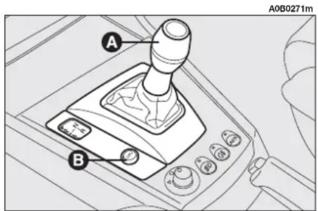
text_image
A B A0B0271mfig. 130
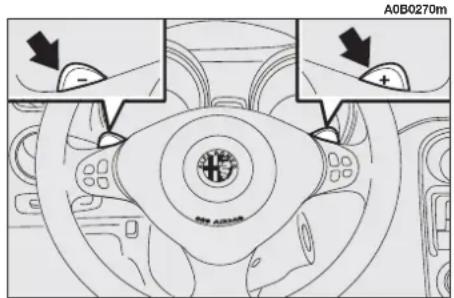
text_image
A0B0270m -fig. 131
When shifting gear, releasing the accelerator pedal is not necessary because the Selespeed system directly controls the engine so as to:
— reduce and then increase the engine torque;
— adapt the engine speed to the new gear ratio engaged.
When downshifting, double de-clutching (acceleration of the engine to bring it to the speed necessary with the new gear ratio) is carried out automatically.
The move to neutral (N) command is accepted when the car speed exceeds 20 km/h.
The command to engage reverse gear (R) is accepted only if the car is stationary.
With the accelerator pedal pressed by over 60% of its stroke and with an engine speed of over 5,000 rpm, gearshifting becomes quicker.
In the MANUAL mode there are some automatic/safety devices which make driving easier:
— when slowing down, the clutch is opened and the gear ratio is reduced automatically to be ready for possibly picking up speed again; if not, stopping the vehicle, first gear (1) will be engaged automatically;
— request to change gear that could take the engine above the maximum rpm or below the minimum permissible rpm are not accepted;
— if the engine reaches the maximum permissible rpm and accelerating continues (without coming into operation of the VDC system), the system automatically engages a higher gear; with the activation of the VDC system, with the maximum engine rpm, gear shifting is excluded;
— if sticking occurs during the engagement of a gear, the system firstly tries to engage the required gear again and, if it is still not possible, it automatically engages the immediately higher one to avoid leaving the vehicle in neutral speed.
WARNING It is advisable to wait for a gearshift to end before requesting another one, this will avoid multiple requests in quick succession.
AUTOMATIC OPERATION (CITY)
The CITY automatic operating mode is selected pressing the button (A-fig. 132), at the base of the gearshift lever.
In addition to the gear, the display on the rev counter will show the word CITY.
The system decides directly when gearshifting according to the engine running speed and the driving style.
Quickly releasing the accelerator pedal, the system does not engage a higher gear in order to maintain an adequate level of engine brake.
FAILURE SIGNALLING
Failures to the Selespeed gearbox are indicated by the ☐ (A-fig. 133) warning light on the instrument cluster.
When the system is turned on (turning the ignition key to MAR), the warning light should turn on glowing steadily for about 4 seconds and then turn off.
If the warning light stays on it means that a fault to the gearbox has been detected; at the same time a buzzer sounds intermittently for 4 seconds to attract the driver's attention.

If the warning light comes on, contact the Alfa Romeo Authorized Services as soon as possible to remove the fault.
In the case of a fault to the gearshift lever, the system automatically activates the automatic CITY mode to allow the car to reach the nearest Authorized Alfa Romeo Services to have the fault detected eliminated.
In the event of faults to other components of the gearbox, the system only allows the engagement of certain ratios: first gear (1), second (2) and reverse (R).

text_image
A0B0269m Afig. 132
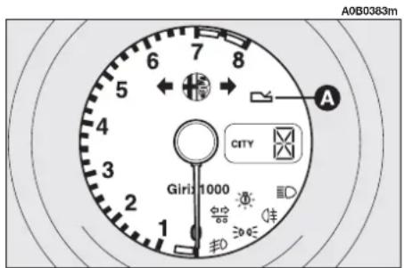
text_image
A0B0383m 6 7 8 5 4 3 2 1 Girl 1000 City 垫 扣fig. 133

WARNING
In case of transmission fault, contact the Alfa Romeo Authorized Services as soon as possible to check the system.
SIGNALLING WITH THE BUZZER
The buzzer is activated when:
— reverse gear (R) is engaged;
— the vehicle is parked with the gearbox at neutral (N); this can be seen turning the ignition key to STOP;
— clutch overheating takes place during pick-up;
— the car moves in the opposite direction to the gear engaged (e.g.: the car tends to do downhill with reverse gear engaged);
— in the event of gearbox failure;
— the system has automatically engaged neutral (N) after:
- there is no action on the accelerator and/or brake pedal for at least 3 minutes;
- the brake pedal is pressed for over 10 minutes;
- the driver's door is opened and the accelerator and brake pedal are not pressed for at least 1 second;
• detection of a gearbox fault.
PARKING THE VEHICLE
To park the car safely it is absolutely necessary to engage first gear (1) or reverse (R) and, when on a sloping road, also engage the hand-brake.
Turning the engine off with the car facing uphill and a gear engaged, it is absolutely necessary to wait for the display on the rev counter to go off before releasing the brake pedal, so that the clutch has innested completely.
If the gearbox is in neutral (N) and you want to engage a parking gear, it is necessary to activate the system and engage the gear (1) or reverse (R) with your foot on the brake pedal.
TOWING THE VEHICLE
WARNING For towing the vehicle, adhere to local regulations. Make sure that the gearbox is in neutral (N) (checking that the car moves when pushed) and proceed as for towing a normal car with mechanical gearbox following the instructions given in the chapter "In an emergency".
Should it be impossible to set to neutral, do not tow the vehicle; contact Alfa Romeo Authorised Services.

WARNING
Do not start the engine when towing the vehicle.
Q-SYSTEM
AUTOMATIC GEARBOX
(optional for versions/markets where applicable)
The 2.5 V6 24V engine can be supplied with an automatic gearbox which in addition to the normal functions, makes it possible to shift gear by hand moving the selector lever to the special sector, Q-System device.
WARNING To be able to use the automatic gearbox correctly, the description given in this chapter should be read thoroughly in order to learn the correct, allowed operations also in concerning the Shift-lock and Key-lock safety devices with which the gearbox is fitted right from the start.
STARTING THE ENGINE
The engine can only be started with the gearshift lever (fig. 134) in position P or N.
For safety reasons, you are advised to start the engine with the brake pedal pressed.
WARNING When moving off, after having started the engine, do not press the accelerator pedal before and while moving the gearshift lever. This is particularly important when the engine is cold.
MOVING OFF
After starting, with the engine idling and keeping the brake pedal pressed (Shift-lock safety device), move the gearshift lever (fig. 134) to position D, or to the manual position. Release the brake pedal and gradually press the accelerator pedal.
WARNING Moving the lever from position P, with the ignition key at MAR, is only allowed with the brake pedal pressed (Shift-lock safety device).
To move the lever, raise the ring (A-fig. 134) under the gearshift lever knob.
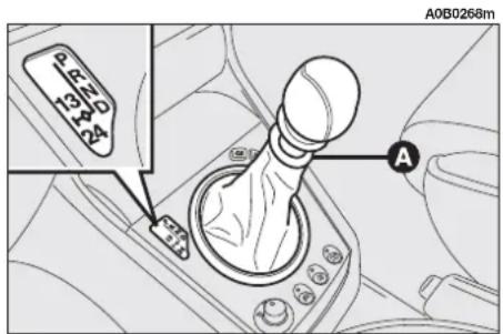
text_image
A0B0268m P 13 N D 24 Afig. 134
In an emergency (failures, flat battery, etc.), it is possible to move the lever from position P, pressing the special mechanical button under the gearshift lever cover, in the area (A-fig. 135); at the same time move the lever from position P to the required position. If the engine is being started, move the lever to position N, which is the only one that allows this operation in this case.
WARNING The ignition key in the STOP position can only be removed from the ignition switch provided that the gearshift lever is at P (Key-lock).
In an emergency (failures, flat battery, etc.), it is possible to remove the ignition key also with the selector lever not positioned at P.
Press the release device (A-fig. 136), next to the ignition switch inside the trim, with your finger removing the key at the same time.
Do not take the car to peak performance until the engine has reached normal operating temperature.
SELECTING AUTOMATIC/ MANUAL GEARSHIFTING
The main feature of this gearbox is the possibility of using it either automatically or manually. The choice of the operating mode is carried out positioning the gearshift lever in the right sector (automatic gearshifting) or in the left sector (manual gearshifting).
The gearbox operating mode and the gear engaged are shown on the display inside the rev counter (A-fig. 137).

text_image
A0B0267mfig. 135

text_image
A0B0266m Afig. 136
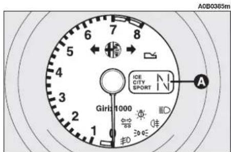
text_image
A0B0365m 6 7 8 5 4 3 2 1 Girli 1000 ICE CITY SPORT A 66 90 90 90fig. 137
AUTOMATIC OPERATION
Selector lever
For automatic gearshifting, move the gearshift lever to the right sector (fig. 138) in one of the following positions:
P - park (the engine can be started)
R - reverse
N - neutral (the engine can be started)
D - automatic forward gear.
Raise the ring (A-fig. 138) placed under the gearshift lever knob for shifting:
— from P to R and vice versa
—from N to R .
P - Park
To prevent accidental engagements, moving the lever to position P is only allowed raising the ring (A-fig. 138) placed under the gearshift lever knob.
When the car is being parked, move the lever to this position. A device in the gearbox will lock the driving wheels.

WARNING
Always pull the hand-brake completely before the car.
Move the gearshift lever to position P when getting out of the car leaving the engine running.
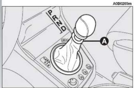
text_image
PEND A A0B0265mfig. 138
R - Reverse
Move the gearshift lever to R with the car stationary, the engine idling and the brake pedal pressed.
To prevent accidental engagements, moving the lever to this position is only allowed raising the ring (A-fig. 138) placed under the gearshift lever knob.
With the lever in position R the reversing lights turn on and a beep is sounded for safety reasons to indicate that reverse gear has been engaged.
Before moving the lever, press the brake pedal: the car must be stationary.
WARNING With the lever in position R, reverse gear is not engaged if the vehicle speed is above the established level. When the car speed falls below this level, reverse gear is engaged and remains engaged even if the speed returns above the limit.
N - Neutral
This is the neutral position to be used when the car has to be pushed or towed.

WARNING
With the engine idling, when moving the lever to
position N the car tends to move even if it is on level ground: keep the brake pedal pressed when the lever is in position N.
D - Automatic forward gear
This is the position to be used always under "normal" driving conditions, for example on the motorway and urban roads and when wanting to minimise fuel consumption (combined with the CITY driving mode).
When the lever is in this position, the gearbox automatically selects the four available speeds. It is also the position to be used for the ICE driving mode.

WARNING
With the engine idling and the lever in position D the vehicle tends to move: always keep the brake pedal pressed until moving off.
Shifting to lower gear (Kick down)
In the event of the need to accelerate heavily (e.g. for overtaking) pressing the accelerator fully home beyond the stiff point will cause automatic kick down to a shorter ratio, engine speed conditions permitting.
Releasing the accelerator pedal as soon as the stiff point has been passed, the gearbox shifts to the optimum ratio in relation to the driving mode, throttle opening position and selector lever position.
The Kick-down function is advised only for overtaking or fast accelerating to avoid increasing fuel consumption.
Kick-down is cut off automatically in the ICE driving mode.
SELECTING THE DRIVING MODES
The automatic gearbox for this car is controlled electronically and includes the selection of three different driving modes, thereby giving the best response in terms of driving comfort, consumption levels, sporty performance and travelling safety.
The three driving modes CITY, SPORT and ICE selected by 2 buttons on the centre console (fig. 139).
The C/S button (A-fig. 139) selects the CITY or SPORT functions, the ICE button (B-fig. 139) selects the mode.
With the ignition key at MAR, the driving mode selected is indicated by the lighting up of the corresponding word on the display on the instrument cluster (rev counter):
CITY (Boston (A-fig. 139) pressed):
This is used under normal operating conditions; it gives preference to comfortable driving and balanced consumption control engaging gears at relatively low engine speed.
SPORT (button A:fig. 139) pressed):
This is selected when wanting to avail of the vehicle's peak performance for sporty driving or on demanding routes.
Driving in the SPORT mode increases fuel consumption.
WARNING The CITY or SPORT driving modes can be selected under any condition (vehicle stationary or on the move).
WARNING When the car is started with a cold engine, the system selects the SPORT driving mode, even if the CITY mode has been selected, until the engine reaches normal operating temperature.
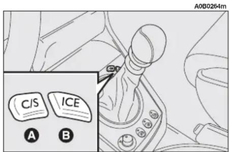
text_image
A0B0264m C/S ICE A Bfig. 139
ICE (ICE) button (B-fig. 133) pressed):
This driving mode is recommended when the road surface offers poor grip (snow, ice, etc.). Moving off takes place in 2^nd gear.
The ICE driving mode is available only with the selector lever at D.
Moving the lever from D, the ICE mode is automatically cut off.
WARNING The ICE driving mode can be engaged pressing the corresponding button also with the car on the move, provided that the speed is below 45 km/h.
Moving the gearshift lever to the manual sector is only possible from position D.
Passing to manual gearshift control is possible under all driving conditions; however, the system will allow engagement only of the gear consistent with engine rpm and the current speed of the vehicle.
Gearshifting takes place as for a normal manual gearbox.

WARNING
When manual operation is set (Q-System device) and a high gear is engaged, to accelerate rapidly, for example for overtaking, it is necessary to shift to a lower gear by hand, as for normal cars with mechanical gearbox.
Moving the lever back to position D the gearbox will resume automatic operation instantly, engaging the ratio in accordance with the driving characteristics and driving mode selected.
STOPPING THE CAR
To stop the car, simply press the brake pedal, regardless of the position of the gearshift lever.

WARNING
With the engine idling even on level ground, if the pedal is not kept pressed, tends to move.

text_image
A0B0263m 13 24 Dfig. 140
FAULT SIGNALLING
Automatic gearbox faults are indicated by the □ warning light (A-fig. 141) on the instrument cluster as follows:
- warning light glowing steadily = maximum automatic gearbox oil temperature;
- warning light flashing = automatic gearbox fault.
Turning the ignition key to MAR the warning light should turn on and go out after approx. 4 seconds.
If the warning light stays on or turns on during travelling, it indicates a gearbox fault (flashing) or overheated gearbox oil (glowing steadily).
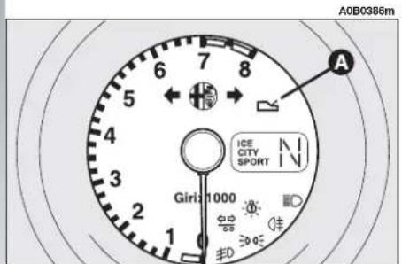
text_image
A0B0386m A Girii 1000 ICE CITY SPORTfig. 141
Warning light glowing steadily
If the warning light turns on and glows steadily when the car is travelling, it indicates that the gearbox oil has reached the maximum established temperature.
The automatic control system provides an emergency programme.
It is however advisable to stop the car, move the lever to P or N and let the engine idle until the warning light goes out. Resume driving without demanding high performance from the engine.
If the warning light comes on again, it is necessary to stop again with the engine idling until it goes out again.
If the interval between one lighting up of the warning light and the next is below 15 minutes, you are advised to stop the car, turn off the engine and wait for the engine-gearbox unit to cool down completely.
Warning light flashing
The flashing of the warning light when travelling indicates a fault in the automatic gearbox.
The automatic control system provides an emergency programme. Under these circumstances, you are advised to stop the car and turn off the engine; in fact, the next time the engine is started, the self-diagnostics system could cut off the fault which will, however, be memorised by the electronic control device.
Conversely, if the fault remains (warning light (A- fig. 141) flashing), it is necessary to select the gears manually as if driving a car with mechanical gearbox, bearing in mind that the only two speeds available are the 2^nd and 4^th gear, as shown in the table below:
Gear engaged Gear ratio manually available
| 1^st | 2^nd |
| 2^nd | 2^nd |
| 3^rd | 4^th |
| 4^th | 4^th |
It is possible to engage reverse gear.

If the indicator light remains flashing, contact the Alfa Romeo Authorized
Service Centers as soon as possible to remove the fault.
If a fault is indicated when the engine is started, this means that the gearbox control system had detected and memorised a fault during the journey prior to switching the engine off. In this case, too, contact Alfa Romeo Authorized Services to have the automatic gearbox checked over.

WARNING
When travelling with a faulty gearbox, the reverse lock might not work: absolutely never move the lever to position R with the car on the move.

WARNING
When driving with a faulty gearbox, drive with the utmost care considering the restricted performance levels (in terms of acceleration and speed) the car can offer.
ACOUSTIC WARNING
This comes into operation for about 18 seconds when:
— the driver's door is open and/or the engine is off with the selector lever in a position other than P;
— position R (reverse) is engaged.
PUSH STARTING
Starting the car by pushing or towing is not possible. In the event of an emergency, when the battery is flat, start the car with a suitable emergency battery, following the instructions given in the chapter "In an emergency".
TOWING THE CAR
WARNING For towing the car, abide by current local regulations. Also follow the instructions given in the chapter "In an emergency".
If the car needs to be towed, observe the following recommendations:
— if possible, put the car on a rescue vehicle;
— if this is not possible, tow the car by raising the driving wheels (front) from the ground;
— if this, too, is not possible, the car may only be towed for 50 km at a speed below 50 km/h.
The gearshift lever should be at position N for towing.

WARNING
Do not start the engine when the vehicle is being
towed.

The failure to follow the above instructions may cause serious damage to
the automatic gearbox.

Cars with automatic gearbox may be towed only for short distances and at low speed: if longer towing is necessary, the driving wheels must be raised to prevent the gearbox from being pulled into rotation during towing.
INTERNAL FITTINGS
GLOVEBOX
On the dashboard there is a key glovebox with light.

WARNING
Do not travel with the glovebox open; it could
harm the passenger in the event of an accident.
The compartment is lit by a courtesy light when it is open (when the ignition key is at MAR (B-fig. 143).
There is a recess on the lid (C-fig. 143) for inserting a pen or pencil. For the versions / markets where provided, the closure flap is fitted with a lock. The lock can be opened/closed using the ignition key.
GRAB HANDLES (fig. 144)
Grab handles are set above the front doors.
Two grab handles (A) fitted with a coat hook (B) are located above the rear doors.
To open the glovebox use lever (A-fig. 142).

text_image
A0B0587m Afig. 142
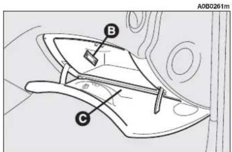
text_image
A0B0261m B Cfig. 143

text_image
A0B0124m A Bfig. 144
CEILING LIGHTS
The car is fitted with passenger's compartment ceiling lights (front/rear) with gradual switching on/off. Timings, defined as max. switching on time elapsing between the end of gradual switching on and the start of gradual switching off are as follows:
1) approx. 6 seconds when:
— unlocking the doors manually or by the remote control
— closing the driver's door to get into the car and fit the key into the ignition switch
— removing the key from the ignition switch.
2) approx. 3 minutes from the door opening.
WARNING With ignition key at STOP or when opening a door or the tailgate 15 minutes timing is activated, then ceiling lights go off. Timing restarts each time a door/tailgate is opened.
Front roof light (fig. 145)
The roof light comprises two lights with the control switch.
With switch (A) in the central position (1), both lights turn on when a door is opened.
When the doors are closed, a timer is activated for about 7 seconds, to allow the car to be started. The lights go out when the ignition key is turned to MAR (with the doors closed).
Moving switch (A) to the left (position 0), the lights stay off (position OFF).
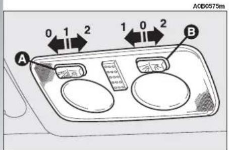
text_image
A0B0575m 0 1 2 1 0 2 A Bfig. 145
Moving switch (A) to the right (position 2) both lights stay on.
The spot function is operated by switch (B).
Moving switch (B) to the left (position 1) the left spot light turns on. Moving switch to the right (position 2) the right spot light turns on.
With switch (B) in the central position (position 0) the spotlights stay off.
WARNING Before leaving the car, make sure that both switches are in the central position. This way, the roof lights will go out when the doors are closed. If a door is left open, the lights will go out automatically after a few seconds.
To turn them on again, simply open another door or close the same one and open it again.
Courtesy light (fig. 146) (where required)
Lowering the passenger's sun visor, the courtesy light on the roof lining can be seen.
This light makes it possible to use the courtesy mirror under conditions with dim light.
On Sportwagon versions there is also a courtesy light under the driver's sun visor.
Use switch (A) to turn it on and off, with the ignition key at MAR.
Rear roof light (fig. 147) (except versions with sunroof)
In correspondence with each rear door there is a light which turns on automatically when a door is opened.
They are timed and work in the same way as described for the front roof light.
They can be turned on and off by hand pressing the transparent cover (A) on the circular impression.
Centre rear roof lamp (fig. 148) (only versions with sunroof)
On the roof lamp there is a switch with three positions.
When the switch (A) is in the central position (O) the roof lamp turns on automatically when a door is opened.
Lighting up is timed and it works as described for the front roof lamp.
Moving the switch to the right (position 1) the roof lamp stays off all the time.
Moving the switch to the left (position 2) the roof lamp stays on all the time.
WARNING Before leaving the car make sure that the switch (A) is in the central position (0), so that the lamp goes out when the doors are closed.
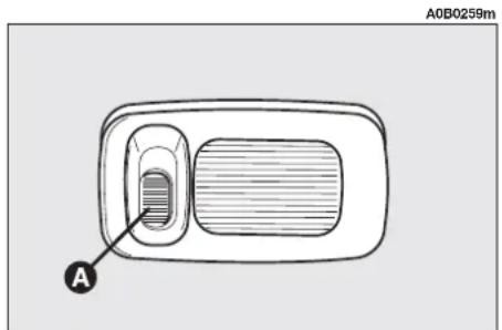
text_image
A0B0259m Afig. 146
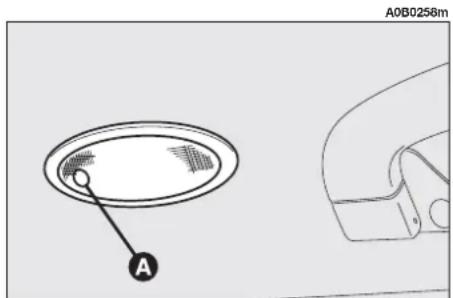
text_image
A0B0258m Afig. 147
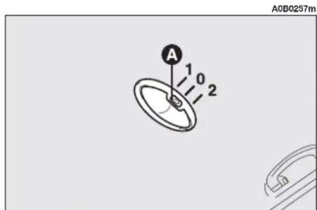
text_image
A 1 0 2 A0B0257mfig. 148
FRONT ASHTRAY AND CIGAR LIGHTER (fig. 149)
To open the ashtray push and release the front of the ashtray.
To use the cigar lighter press, with the ignition key at MAR, button (B); after some seconds the knob will return automatically to its initial position and the cigar lighter is ready for use.
Remove the tray (A) to empty and clean the ashtray.

WARNING
The cigar lighter gets extremely hot. Handle with
care and prevent its use by children: danger of fire and/or burning.

Always ensure that the cigar lighter has turned off.

WARNING
Do not use the ashtray as paper bin: it could set on fire on contact with cigarette stubs.
REAR ASHTRAYS (fig. 150)
An ashtray (A) is fitted to each rear door. To open, pull downwards as shown below.

text_image
A0B0256m A Bfig. 149

text_image
A0B0255m Afig. 150
ODDMENTS RECESSES ON CENTRE CONSOLE (fig. 151)
Centre recess
On the centre console near the handbrake lever, there are the following oddments recesses:
- oddments recesses (A) and (B);
- coin recess (C).
ODDMENTS RECESSES ON DASHBOARD
Left side recess (fig. 152)
An oddments recess (A) is provided on the lower side of the dashboard, on the left of the steering column.
FRONT DOORS COMPARTMENTS AND POCKETS (fig. 153)
Each front door has an oddments pocket (A).

text_image
A B C A0B0283mfig. 151
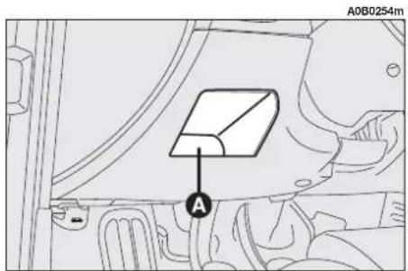
text_image
A0B0254m Afig. 152

text_image
AOB0253m Afig. 153
SUN VISORS
They can be adjusted frontally and laterally.
On the back of the visors there is a courtesy mirror with sliding cover (A-fig. 154), lit by the lamp (B).
The passenger's sun visor bears also the symbol for correct use of children's seats in cars equipped with passenger's airbag. For further information, see the descriptions given in paragraph "Passenger's front airbag" in this chapter.
TELEPHONE PROVISION
(on request for versions/markets where applicable)
On request for versions/markets where applicable, the car may be fitted with a provision for the installation of a cellular telephone.
This provision comprises:
— sound system two-function aerial + cellular phone;
— supply and connection cables with specific connector for voice kit connection.

The voice kit must be purchased separately by the customer, since it has to be compatible with the customer's own cellular phone.

For the installation of the cellular phone and connection to the provision in the car, contact only Alfa Romeo Authorized Services; this will guarantee first-rate results with no possibility of any inconvenience that may compromise the safety of the vehicle.
ACCESSORIES PURCHASED BY THE OWNER
If, after purchasing your car, you want to install electric accessories that require permanent power supply (burglar alarm, voice function, radionavigator with satellite burglar alarm, etc.) or other accessories that affect the vehicle's electric load, contact Alfa Romeo Authorized Services, whose qualified staff is able to recommend the most suitable equipment of the Lineaccessori Alfa Romeo, and also assess the electric absorption of the same, checking if the vehicle can withstand the required load or if a battery of greater power must be used.

text_image
A0B0252m A B B Afig. 154
RADIO TRANSMITTERS AND CELLPHONES
Cellphones and other radio transmitters (e.g. CB radios) cannot be used inside the vehicle, unless you use a separate aerial mounted outside the vehicle.
The transmission and reception efficiency of this equipment may also be affected by the shielding effect of the vehicle's body.

WARNING
The use of cellphones, CB radios or similar inside the passenger compartment (without an outside aerial) produces electromagnetic RF fields; if these are amplified by the resonance inside the passenger compartment, they may not only result in a potential health hazard, or poor functioning of the electronic systems such as engine control units, ABS/EBD control units, etc., fitted to the vehicle, but also put the safety of your vehicle in jeopardy.
SUNROOF
(optional for versions/markets where applicable)
The sunroof can only be operated when the ignition key is in the MAR position.

WARNING
Improper use of the sunroof can be dangerous. Before and while operating it, always make sure that the passengers are not exposed to the risk of harm caused either directly by the sunroof in motion or by personal items drawn or knocked by it.

Do not open the sunroof when snow or ice are on the roof as this may dam-
age it.

WARNING
When leaving the vehicle, the ignition key should always be removed to avoid accidents involving the sunroof which could be inadvertently operated by any passenger remaining in the vehicle.
SLIDING FORWARDS/ BACKWARDS (fig. 155-16)
Press control button (A) on rear end (1) to open the roof; press on front end (2) to close it.
When the button is released, the sunroof will stop in that position.
For versions/markets where applicable, during opening the roof stops automatically in an intermediate position called "Comfort", which is advised for average speeds. In this case, complete opening is obtained pressing the rear end (1) of button (A) again. When closing, the roof does not stop in the "Comfort" position.
The sunroof is fitted with a curtain below, which prevents sun radiation and is drawn by hand using a catch.
The curtain is drawn by the roof when the roof opens and is pushed completely inside the roof panel when the roof is opened completely. With the closing movement the curtain will come out partially so that the hand catch is accessible (A-fig. 157).
RAISING TO THE QUARTERLIGHT POSITION
This can only be achieved (fig. 158) when the sunroof is completely closed, pressing front end (2) of the control button (A-fig. 159).
Press the rear end (1) of the button (A-fig. 159) to return the sunroof to the horizontal position (roof closed).

WARNING
Open and close the roof only when the vehicle is
stationary.
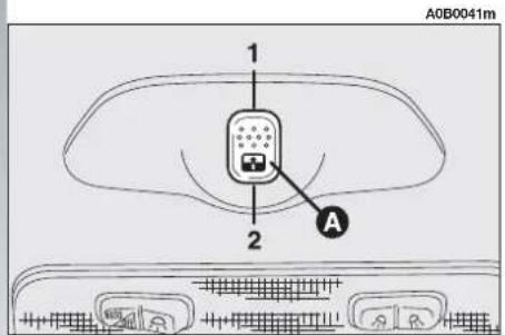
text_image
A0B0041m 1 2 Afig. 155
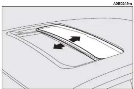
natural_image
Top-down diagram of a car's front air vent with directional arrows indicating airflow or movement (no text or symbols)fig. 156

text_image
A0B0248m Afig. 157
EMERGENCY OPERATION
If the electrical control device does not work, the sunroof can be opened manually as follows:
— apply leverage to the points indicated by the arrows and remove the plate with switch (D-fig. 159);
— use the outfit screwdriver or the special wrench (B-fig. 160) supplied for the versions / market where provided, and located in the object holder drawer, push on and turn the sunroof control bushing (C-fig. 160) clockwise to open it and anti-clockwise to close it.
WARNING At the end of the operation, before removing the screwdriver or the wrench, it is necessary to turn it by half a turn in the direction opposite to that used, until a click is felt.
LUGGAGE COMPARTMENT
The boot lid can be opened from outside the vehicle (pressing the button on the key) and from inside the vehicle.
WARNING If the boot is not properly shut, the warning light will come on on the instrument panel or (where applicable) on the Infocenter display (together with relevant message).

natural_image
Diagram of a car interior showing a curved surface with directional arrows indicating movement or flow (no text or symbols)fig. 158

text_image
A0B0246m 1 2 A Dfig. 159
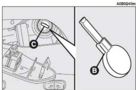
text_image
A0B0245m C Bfig. 160
OPENING FROM INSIDE (fig. 161)
To open the boot from inside the passenger compartment, pull the lever (A), at the side of the driver's seat.

WARNING
Only use the boot opening lever with the vehicle sta-
Lifting the boot lid is made easier by the action of gas springs.

the gas springs are cali-brated to guarantee correct operation with loading
specified by the manufacturer. Arbitrary additions to the boot lid (spoiler, etc.) may affect its operation and safety.

text_image
A A0B0042mfig. 161
OPENING WITH REMOTE CONTROL (fig. 162)
The luggage compartment can be opened by remote control from outside pressing the button (C), also when the electronic alarm is on (where applicable).
In this case, the alarm system switches off volumetric protection and the boot lid control sensor. The system also sounds two beeps and the arrows light up for about three seconds (with the exception of versions for certain markets).
Closing the boot again the control functions are restored, the system sounds two beeps and the arrows light up for about three seconds (with the exception of versions for certain markets).

text_image
A0B0743mfig. 162
CLOSING THE BOOT
To close the boot, lower it and press down above the locking mechanism until it is heard to click into place.
BOOT LIGHTING (fig. 163)
Opening the boot, the light (A) in the upper part of the boot turns on automatically.
The light goes out closing the boot or after a few minutes (about 15) if the boot is left open. In this case, to turn it on again close the boot, then open it again.
SECURING THE LOAD (fig. 164-165)
The load carried may be blocked with straps hooked to the special rings in the boot corners.
The rings also serve to secure the luggage retaining net (available upon request, for versions/markets where applicable) c/o Alfa Romeo Authorized Services.
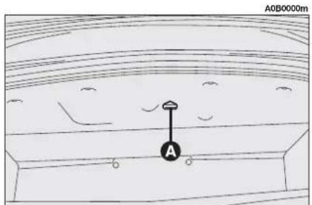
text_image
A0B0000m Afig. 163

natural_image
Diagram showing two directional arrows pointing to a rectangular area with circular markers, no text or symbols present.fig. 164

text_image
A0B0243mfig. 165
CAUTIONS FOR CARRYING LUGGAGE
Travelling at night with a load in the boot it is necessary to adjust the height of the low beam headlights (see next paragraph "Headlights" in this chapter). For correct use of the aiming device, also make sure that the load does not exceed the values given in the same paragraph.

WARNING
Do not load the luggage compartment above the permitted maximum (see "Technical specifications"). Also make sure that the objects contained in the boot are well secured to prevent them from being thrown forward causing harm to the passengers in the event of sharp braking.

WARNING
A heavy load that has not been secured may cause harm to passengers in the of an accident.

WARNING
When wanting to carry a spare can of petrol, this is done in compliance with only using a certified can, triately fastened to the load at eyelets. Even so, the risk is increased.
BONNET
The lever used to open the bonnet is located under the left end of the dashboard.
To open:
— Pull the lever (A-fig. 166) until the bonnet clicks open.

WARNING
Only with the car stationary.

text_image
A A0B0049mfig. 166

WARNING
Before lifting the bonnet, make sure that the windscreen wiper arms are not raised from the windscreen.
— Press the safety lever (fig. 167) upwards.
— Raise the bonnet.
WARNING Bonnet raising is aided by two gas springs. Do not tamper with these springs and accompany the bonnet while raising it.

WARNING
DANGER-SERIOUS INJURY. When carrying out checks or maintenance operations in the engine compartment, take special care not to bump the head on the raised bonnet.

WARNING
If checks need to be carried out in the engine compartment when the engine is still warm, keep away from the fan as it could start up even when the key is removed from the ignition. Wait until the engine cools down.

WARNING
Scarves, ties and loose clothing may be caught in ving parts.

natural_image
Line drawing of a car interior showing dashboard and steering wheel (no text or symbols)fig. 167
To close:
— lower the bonnet to approx. 20 cm from the engine compartment, then let it drop. Try lifting it to make sure that it is shut completely and not simply caught in the safety position.
If the bonnet does not close properly, do not push it down but open it again and repeat the above procedure.

WARNING
For safety reasons the bonnet shall always be fully closed when travelling. It is check for proper bonnet. If the bonnet is left inadvertently open, stop the car imely and close the bonnet.
ROOF RACK PROVISION
The car is set for mounting special roof racks.
Roof racks, especially designed for this car, must be fastened to pins (A-fig. 168) set under the packing, as shown in the figure.

WARNING
After a few kilometres, check that the fastening screws are firmly tightened.

Strictly comply with the regulations in force concerning the maximum over-ensions.

WARNING
Distribute the load evenly and when driving, bear in mind the increased sensitivity to side wind.
A0B0142m
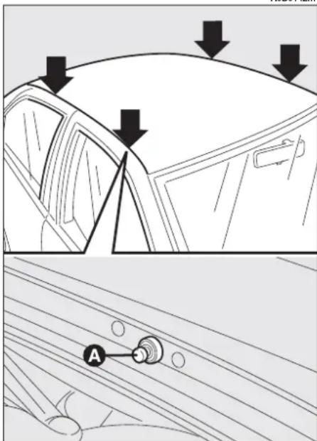
text_image
Diagram showing car head and dashboard with arrows indicating downward motion, plus a labeled component 'A' in the dashboard.fig. 168
HEADLIGHTS
LIGHT BEAM AIMING
WARNING The adjustment of the headlights is vital to your safety and comfort and to that of other road users. The adjustment of the headlights is also governed by precise regulations. To guarantee both to yourself and to the other drivers the best visibility conditions when travelling with the headlights on, the vehicle must have its headlights properly adjusted.
Contact Alfa Romeo Authorized Services to have the headlights correctly adjusted.
IMPORTANT On the inside surface of the headlight there could appear a slight coat of fogging; this does not show a defect, since it is a natural occurrence due to low temperature and to the degree of humidity in the air; it will soon disappear as soon as the lights are turned on. The presence of drops inside the headlight shows water seepage: refer to the Alfa Romeo Dealership.
COMPENSATION FOR TILT (fig. 169)
If the car is fitted with xenon headlights, beam aiming is electronic and therefore control (A) on the mask near the steering column is not present.
When the vehicle is loaded, the beam from the headlights is raised due to the backwards tilt of the vehicle.
In this case the headlights must be adjusted using control (A) located on the plate at the side of the steering column.
This control has four positions corresponding to various vehicle loads given below:
— position 0: 1 or 2 people occupying front seats, full fuel tank, on-board equipment present;
— position 1: 5 people on-board;
— position 2: 5 people on-board, luggage compartment full (50 kg approximately);
— position 3: driver and 300 kg in luggage compartment.
ADJUSTING THE FRONT FOGLIGHTS
(for versions/markets where applicable)
To adjust the height of the beam of the front foglights, act on adjusting screw (A-fig. 170).

Contact Alfa Romeo Authorized Services to have the headlights correctly ad-
justed.
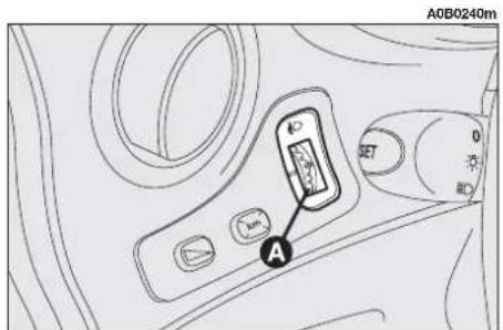
text_image
A0B0240m SET A DCIfig. 169

WARNING
Check the positioning of the headlight beams every
time you change the load to be carried.
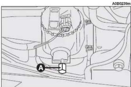
text_image
A0B0239m Afig. 170
GAS DISCHARGE HEADLIGHTS (optional for versions/markets where applicable)
The gas (xenon) discharge headlights operate with a voltaic arc, in an ambient saturated with pressure xenon, instead of the glow filament.
The resulting illumination is sensibly higher to that of conventional lamps, both for light quality (clearer light) and for the width and positioning of the illuminated area.
The advantages of better illumination can be perceived (due to less eyesight fatigue and greater orientation capacity for the driver, which in turn means higher driving safety) especially in case of bad weather, fog and/or insufficient road signs, thanks to the better illumination of the side parts of the visual field, normally obscured.
The large increase of the side part illumination increases driving safety since it allows the driver to better see the other users on the edge of the road (pedestrians, cyclists and bikers).
The triggering of the voltaic arc requires a very high voltage, while subsequent power supply can take place at a low voltage.
The headlights achieve their top luminosity approx. 15 seconds after they are switched on.
The intense light produced by this type of headlights requires the use of an automatic system to keep headlight trim constant and avoid dazzling the vehicles coming from the opposite direction in case of braking, acceleration or when carrying loads.
The electromechanical system to automatically keep constant trim makes the headlight tilt compensating device unnecessary.
The xenon lamps have very long life which makes possible fault very unlikely.

WARNING
If necessary, have the system checked and repairs (if
any) made only by Alfa Romeo Authorized Services.
DIPPED BEAM HEADLIGHT AIMING FOR LEFT-HAND/RIGHT-HAND DRIVING (only for versions with gas discharge headlights)
As regards cars equipped with gas discharge headlights (xenon lamps) (optional for versions/markets where applicable) with very great lighting power, when passing from a country with right-hand driving to one with left-hand driving, or vice versa, it is necessary to modify the orientation of the dipped beam headlights, to optimize the illumination of the road edge and avoid dazzling the vehicles coming from the opposite direction.
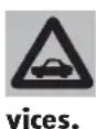
To have this operation carried out, contact Alfa Romeo Authorized Ser-

WARNING
When you go back to your country of origin, remember to have the dipped beam headlight orientation modified again.
ABS
The car is fitted with an ABS system which prevents wheel lock when braking, better exploits wheel grip and keeps the vehicle controllable within the limits of the available grip also during emergency braking.
The driver can feel that the ABS is operational by a light pulsing of the brake pedal, accompanied by noise.
This should not be interpreted as malfunctioning of the brakes, but it is the signal to the driver that the ABS system is working: it is the warning that the car is travelling at the limit of grip an that, therefore, it is necessary to adapt the speed to the type of road on which you are travelling.
The ABS system is an additional part of the basic braking system; in the event of a fault it is disabled, leaving the braking system in the same conditions as a car without ABS.
In the event of a failure, though being unable to rely on the antilock effect, there is absolutely no adverse effect on vehicle braking performance in terms of braking capacity.
If you have never used a car with ABS before, you are advised to learn how to use it with a few preliminary trials on a slippery surface, naturally under safety conditions and fully adhering to the Highway Code of the country concerned. You are also advised to carefully read the following information.
The advantage of the ABS compared with the conventional system is that it makes it possible to maintain maximum vehicle handling performance also in the case of hard braking under grip limit conditions, avoiding wheel lock.
Do not however expect the braking distance always to be reduced with the ABS system: for example, on soft surfaces such as gravel or fresh snow on slippery surfaces, the distance might increase.
In order to be able to exploit as far as possible the possibility of the antilock system in the case of need, it is wise to follow a few pieces of advice:

WARNING
The ABS exploits the available grip in full, but it can-
not increase it; therefore, caution is required on slippery surfaces, without running unnecessary risks.

WARNING
If the ABS cuts in, it means that the grip limit between
the tyres and the road surface has been reached: it is necessary to slow down and adapt driving to the grip available.

WARNING
In the event of a system fault, with lighting up of
the (w) warning light on the instrument cluster (together with the message + symbol shown by the display), have the vehicle checked immediately by Alfa Romeo Authorized Services, driving slowly to be able to regain full system performance.
Braking on corners always requires the utmost caution, even with the help of the ABS.
The most important piece of advice, however, is the following:

WARNING
When the ABS cuts in and you feel the pedal pulse, do twice the pressure, but keep take pedal firmly pressed to fear; this way you will the shortest possible space, likely with the conditions of and surface.
Following these instructions you will be in a condition to obtain peak braking performance at all times.
WARNING Cars fitted with ABS must only be fitted with wheel rims, tyres and brake linings of the type and brand approved by the Manufacturer.
The braking system is completed by the electronic control braking distribution system called EBD (Electronic Braking Force Distributor) which distributes the braking action through the ABS system control unit and sensors.

WARNING
The car is fitted with an electronic brake distributor
(EBD). If the Ⓜ and Ⓔ warning lights, where required, come on at the same time (together with the message + symbol shown by the display) when the engine is running, there is an EBD system fault; in this case, violent braking may lock the rear wheels too early, with the possibility of skidding. Drive extremely carefully to the nearest Alfa Romeo Authorized Services to have the system checked over.

WARNING
If the Ⓑ low brake fluid warning light comes on (together with the message + symbol shown by the display), stop the car immediately and contact the nearest Alfa Romeo Authorized Services. Indeed, any leak of fluid from the hydraulic system compromises the effectiveness of both the conventional brake system and the system with antilock system.

WARNING
The turning on of the (ABS) warning light (together with the message + symbol shown by the display) with the engine running normally indicates an ABS system fault. In this case the braking system preserves its effectiveness, without however making use of the antilock device. Under these circumstances, the EBD system may fail to give top performance. In this case, too, you are recommended to contact Alfa Romeo Authorized Services immediately, driving in such a way as to avoid abrupt braking, to have the system checked.
VDC AND ASR SYSTEMS
(where required)
VDC SYSTEM (VEHICLE DYNAMICS CONTROL): GENERAL
The VDC is an electronic vehicle stability control system which, acting on the torque and braking the wheels in a differentiated manner, helps to bring the car back to the correct course in the event of loss of grip.
While travelling the car is subjected to lateral and longitudinal forces that may be controlled by the driver up to when the tyres offer adequate road-holding; when this falls below the minimum level, the car starts to deviate from the course required by the driver.
Above all on rough surfaces (such as cobbles, or due to the presence of water, ice or soil), changes in speed (when accelerating or braking) and/or course (bends or the need to avoid obstacles) can cause the tyres to lose grip.
When the sensors detect the conditions that would lead to skidding, the VDC system acts on the engine and brakes generating a stabilising torque.

WARNING
The system performance levels, in terms of active safety, should not induce the driver to run pointless and unjustified risks. Driving conduct should always be suited to the conditions of the road surface, vision and traffic. The responsibility for road safety is always and anyway the vehicle driver's concern.
The VDC system helps the driver to keep control of the car in the event of loss of tyre grip.
The forces induced by the VDC system to control the lack of stability of the car always and anyway depend on the grip between the tyre and the road surface.
The VDC system turns on automatically when the car is started and cannot be switched off. It is however possible to cut off operation of the ASR system pressing the corresponding button on the centre console.
The main components of the VDC system are:
— an electronic control unit which processes the signals received from the various sensors and brings about the most appropriate strategy;
— a sensor that detects the position of the steering wheel;
— four sensors that detect the rotation speed of each wheel;
— a sensor that detects rotation of the car around the vertical axis;
— a sensor that detects lateral acceleration (centrifugal force).
The heart of the VDC system is the VDC control unit which with the data supplied by the sensors installed on the car, calculates the centrifugal forces generated when the car is cornering. The yawing sensor detects the rotations of the car around its own vertical axis. The centrifugal forces generated when the car is cornering are detected by a highly sensitive lateral acceleration sensor.
The stabilising action of the VDC system is based on calculations made by the system's electronic control unit which processes the signals received from the steering wheel rotation, lateral acceleration and individual wheel rotation sensors. These signals allow the control unit to recognise the manoeuvre the driver intends to do when turning the steering wheel.
The control unit processes the information received from the sensors and is therefore capable of detecting the position of the car and comparing it with the trajectory the driver would like to follow instant by instant. In the event of a discrepancy, the control unit chooses and commands the most suitable action to bring the car back to the required course within a fraction of a second: braking one or more wheels at a different braking force and, if necessary it reduces the power transmitted by the engine.
The corrective actions are changed and controlled continuously until the car returns to the required course.
The action of the VDC system considerably increases the active safety of the vehicle under many critical situations and it is particularly useful also when the road surface grip conditions change.

WARNING
For the VDC, ASR and ABS systems to work correctly, the tyres must be of the same brand and type on all wheels, in perfect conditions and above all of the specified type, brand and size.

WARNING
During use of the compact spare wheel, the VDC system continues working. It should be borne in mind that the spare wheel is smaller than a normal tyre, therefore its grip is lower than that of the other tyres of the car.
ASR FUNCTION (ANTISLIP REGULATION): GENERAL
The ASR system integrates the VDC system controlling the vehicle drive and coming into operation automatically each time one or both driving wheels skid.
Two different control systems are activated, depending on the skidding conditions:
— If skidding concerns both driving wheels, because it is caused by the excessive power transmitted, the ASR system cuts in reducing the power transmitted by the engine.
— If skidding concerns only one driving wheel, the ASR system cuts in automatically braking the skidding wheel, with an effect similar to that of a self-locking differential.
The action of the ASR system is particularly helpful under the following conditions:
— Skidding of the inner wheel on a bend, due to the effect of the dynamic changes of the load or over-accelerating.
— Excessive power transmitted to the wheels, also in relation to the conditions of the road surface.
— Acceleration on slippery, snowy or icy surfaces.
— In the case of loss of grip on a wet surface (aquaplaning).
CUTTING IN OF THE VDC SYSTEM
The cutting in of the VDC system is indicated by the flashing of the warning light Ⓐ on the instrument cluster, to inform the driver that the car is in critical conditions of stability and grip.
TURNING ON THE ASR FUNCTION
The ASR function turns on automatically each time the engine is started.
When travelling it is possible to switch the system off and on again pressing the switch (A-fig. 171) on the centre console.
Function disconnection is shown by the led on the ASR button being turned on. If the function is turned off while travelling, it will turn on again automatically the next time the engine is started.
WARNING When driving on snow, with snow chains fitted, if may be helpful to switch off the ASR function: in these conditions in fact, skidding of the driving wheels when moving off helps to obtain better traction.
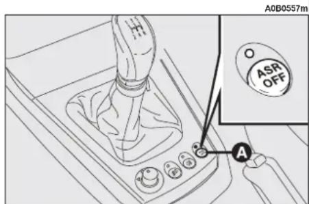
text_image
A0B0557m O ASR OFF Afig. 171
WARNING LIGHT ON INSTRUMENT PANEL
When the ignition key is turned to MAR, the dial warning light Ⓐ comes on but must go out after a few seconds.
If the warning light does not go out, or if it stays on (together with the message + symbol on the display and the coming on of the ASR button led) when the vehicle is running, contact Alfa Romeo Authorized Services.
The flashing of the warning lamp when the vehicle is running indicates the actuation of the VDC system.
VDC system failure warning
In the event of a failure the VDC system disengages automatically and the Ⓐ warning light on the instrument cluster turns on glowing steadily (together with the message + symbol shown on the display and the coming on of the ASR button led).
In the event of a VDC system failure the car behaves like a vehicle not fitted with this system: in any case it is advisable to contact Alfa Romeo Authorized Services as soon as possible.
EOBD SYSTEM
The EOBD (European On Board Diagnosis) system fitted in the car conforms with the 98/69/EC (EURO 3) Directive and the 2001/1/EC Directive, level B (EURO4) for 2.0 JTS, 2.0 JTS Selespeed and JTD 20V Multijet versions.
This system continuously monitors the components of the vehicle related to emissions; it also indicates, when the warning light comes on on the instrument panel (together with the message + symbol shown by the display) that the components in question are in poor conditions.
The objective is the following:
— to keep under control the efficiency of the system;
— to indicate when a malfunction causes an increase in the emissions beyond the threshold established by European regulations;
— to indicate the need to replace the deteriorated components.
The system also has a diagnostic connector, which can be interfaced with adequate instruments, that enables the error codes stored in the control unit to be read, together with a series of specific parameters concerning the operation and diagnosis of the engine.
This check can also be made by the traffic control agents.

If, when the ignition key is turned to MAR, the warning light does not come on or if, when driving, it lights up and emits a fixed light or a flashing one (together with the message + symbol shown by the display), contact an Alfa Romeo Authorized Service Station as soon as possible. The operation of the warning light can also be checked by means of special equipment available to the traffic control officers. Comply with the regulations in force in country where you drive your car.
WARNING After the problem has been resolved, to completely check the system, the Alfa Romeo Authorized Services must carry out tests on a test bench and, if necessary, road tests that could be long.
SOUND SYSTEM
(where applicable)
The fixed sound system, with cassette player (radio with cassette player) or CD player with parametric sound equalizer (radio with CD player) has been designed to suit the specific characteristics of the passenger compartment, with a personalised design that matches the style of the dashboard. The sound system instructions for use are described in the attached supplement.
SOUND SYSTEM PRESETTING SYSTEM
(for versions/markets where applicable)
The car, if not delivered with sound system, is fitted with a glove compartment (fig. 172) on the instrument panel.
Sound system presetting system includes the following:
— sound system power cables;
- front and rear speaker power cables;
- aerial power cable;
— sound system housing;
— aerial on car roof (where provided).
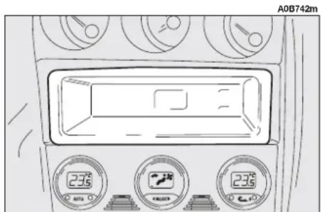
text_image
A0B742m 235 235 235fig. 172
The sound system shall be installed in the proper housing occupied by the glove compartment that can be removed by pressing the two retaining tabs in the glove compartment: here are the power cables.

If after buying the car you want to install the sound system, contact first Alfa
Romeo Authorised Services whose qualified personnel, in addition to suggesting the most suitable devices, will evaluate the overall electric absorption to safeguard the battery. Excessive loadless absorption could damage the battery and lose warranty.
The wiring diagram is the following (fig. 173):
Connector A
A1 N.C.
A2 N.C.
A3 N.C.
A4 + 30 (battery-powered)
A5 Aerial power supply
A6 Light
A7 + 15 (key-powered)
A8 Ground
Connector B
B1 RH rear speaker
B2 RH rear speaker
B3 RH front speaker
B4 RH front speaker
B5 LH front speaker
B6 LH front speaker
B7 LH rear speaker
B8 LH rear speaker
TECHNICAL INFORMATION
Speakers (fig. 174-175)
For cars fitted with presetting system, the sound system includes the following:
- 2 tweeters (A-fig. 174), with 30W power;
- 4 speakers (B-fig. 174) and (A-fig. 175), 165 mm diameter (2 front and 2 rear), with 40W power.
Aerial
For versions/markets where applicable, the aerial can be built into the rear heated window or can be located on the car roof.

text_image
A0B741m A2 A1 B2 B1 A4 A3 B4 B3 A6 A5 B6 B5 A8 A7 B8 B7 A Bfig. 173

text_image
A0B387m A Bfig. 174
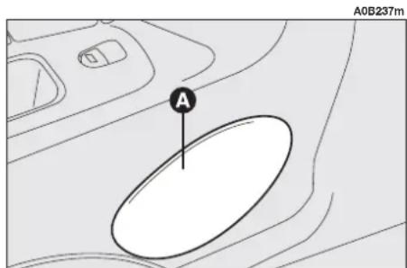
text_image
A A0B237mfig. 175
REFUELLING
PETROL ENGINES

The anti-pollution devices present on the vehicle impose the use of four-star
unleaded fuel with an octane number (R.O.N.) above 95.

Under no circumstances should conventional leaded petrol be used, as this would irreparably damage the catalyst. If the tank is accidentally filled with leaded fuel, even in minute quantities, DO NOT START THE ENGINE. Do not attempt to dilute the petrol with lead free fuel. Drain the entire fuel circuit and tank.
In order to prevent the vehicle being filled with leaded petrol, the diameter of the filler neck is smaller than the nozzle used on pumps delivering leaded petrol.

If the catalyst is not working properly, harmful emissions reach the exhaust, resulting in environment pollution.
JTD ENGINES

The car must be refuelled only with fuel oil for motor vehicles, in conformity with European specification EN590. The use of other products or mixtures may damage the engine irreparably, resulting in invalidation of the warranty for the damage caused. If the tank is accidentally filled with another type of fuel, do not start the engine but drain the tank. If the engine has been run even for a brief period, the tank must be drained together with the entire fuel circuit.
At low temperatures, the degree of fluidity of fuel oil may become insufficient due to the formation of paraffins leading to danger of clogging the fuel oil filter.
Therefore, to avoid inconveniences, summer and winter fuel oils are normally distributed depending on the season.
However, during the intermediate season, characterised by a large difference between outside temperatures ( 0^ C to 15^ C), the quality of the fuel oil distributed to the pumps may not be adequate.
In this case, and above all if the use of the car involves stopping and then starting again at low temperatures (e.g. mountains), make sure the car is filled with winter fuel oil; if not, you are advised to mix the fuel oil with a DIESEL MIX additive in the proportions stated on the can, pouring first the antifreeze and then the fuel oil into the tank.
The DIESEL MIX antifreeze should be mixed with the fuel oil before reactions due to cold take place. Adding it too late will prove pointless.
FUEL CAP (fig. 176)
The fuel flap is released from inside the car, raising the front part of the lever (A).
The fuel cap (A-fig. 177) has a catch to prevent misplacing it (B) that fastens it to the flap (C).
WARNING The fuel tank is sealed hermetically and pressure may build up inside. Any noise of rushing air when the cap is removed is perfectly normal.
WARNING For your safety, make sure that the fuelling pump nozzle is inserted correctly into the housing, before starting the engine.

WARNING
Do not get near the fuel filler with naked flames or lit cigarettes: danger of fire. Also avoid going too near the filler with the face to avoid inhaling harmful vapours.

In case of need, replace the fuel cap only with an original one; otherwise, the efficiency of the petrol vapour recovery system could be badly affected.
EMERGENCY FLAP OPENING DEVICE
If the lever (A-fig. 176) fails to work, it is still possible to open the flap by pulling the cord (A-fig. 178) on the right-hand side of the luggage compartment.
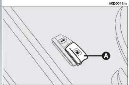
text_image
A0B0044m Afig. 176

text_image
A0B0045m C B Afig. 177
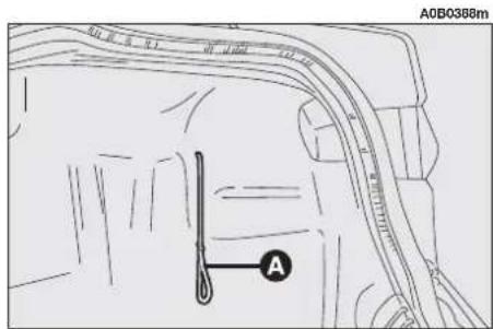
text_image
A0B0388m Afig. 178
PARKING SENSORS (WHERE PROVIDED)
(optional for versions/markets where applicable)
The parking system detects and informs the driver (through an intermittent acoustic signal) about the presence of obstacles in the rear part of the car (fig. 179).
ACTIVATION
The sensors are automatically activated when the reverse gear is engaged.
The sound produced by the acoustic alarm becomes continuous when the distance between the car and the obstacle is less than 30 cm.
ACOUSTIC SIGNAL
When the reverse gear is engaged an intermittent acoustic signal is automatically activated.
The acoustic signal:
— raises with the reduction of distance between the car and the obstacle;
— becomes continuous when the distance between the car and the obstacle is less that 30 cm and stops if the distance raises.
— is constant if the distance is unvaried. If this situation takes place for side sensors, the signal is stopped after about 3 seconds to prevent sound indications when performing manoeuvres near walls.
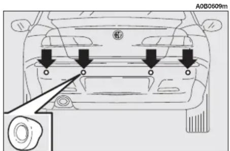
text_image
A0B0609mfig. 179
ENVIRONMENTAL PROTECTION
The design and construction of the vehicle have not only been developed with the traditional aspects of performance and safety in mind, but also take into account the increasingly pressing problems tied to protecting the environment.
The choice of materials, techniques and particular parts are the result of work which has made it possible to drastically reduce the harmful effects on the environment and guarantee respect for the severest international norms.
USE OF NON-TOXIC MATERIALS
None of the components of the vehicle contains asbestos. The padding and the climate control system do not contain CFCs which are held to be responsible for the depletion of the ozone layer.
The colouring agents and the corrosion inhibitors used on the nuts, screws and bolts do not contain cadmium any more, which could pollute the atmosphere or water tables.
EMISSION REDUCING DEVICES (petrol engines)
Trivalent catalytic converter (catalytic silencer)
The exhaust system is fitted with a catalyzer formed of alloys of noble metals. It is housed in a stainless steel container which is able to resist the high operating temperatures.
The catalyzer converts the unburnt hydrocarbons, carbon monoxide and nitrogen oxides present in the exhaust gas (even if in small quantities thanks to the electronic injection and ignition system) into harmless compounds.

WARNING
Due to the high temperatures reached during oper-
ation of the catalytic converter, the vehicle should not be parked over inflammable materials (paper, fuel oils, grass, dry leaves, etc.).
Lambda probe
A sensor (lambda probe) measures the content of oxygen present in the exhaust gas. The signal transmitted by the lambda probe is used by the injection and ignition electronic control unit to adjust the air-fuel mixture.
Anti-evaporation system
As it is impossible, even when the engine is switched off, to prevent the formation of fuel vapours, a system has been devised which imprisons the vapours in a special activated carbon container.
During operation of the engine, these vapours are sucked up and sent to combustion.
EMISSION REDUCING DEVICES (JTD engines)
Oxidising catalytic converter
Converts the polluting substances present in the exhaust gases (carbon monoxide, unburned hydrocarbons and particulate) into harmless substances, thus reducing the fumes and smell that are typical of diesel engines.
The catalytic converter consists of a stainless steel case that houses a ceramic honeycomb body coated with noble metal used as a catalyst.
Exhaust gas recirculation system (E.G.R.)
This system recycles, i.e. re-uses, a varying percentage of the exhaust gases, depending on engine operating conditions.
It is used, when necessary, to control nitric oxides.
CORRECT USE OF THE CAR
STARTING THE ENGINE
WARNING The car is fitted with an electronic engine lock device. If the engine fails to start see "Alfa Romeo CODE system".

In addition to the notes and specifications given below we recommend that, during the initial period, you do not drive to full vehicle performance (for example excessive acceleration, long journeys at top speed, hard braking, etc.).

WARNING
Running the engine in confined areas is extremely dangerous. The engine consumes oxygen and produces carbon monoxide which is a highly toxic and lethal gas.
The ignition switch is fitted with a safety device which obliges the driver to return the ignition key to the STOP position before repeating the starting operation if the engine does not start immediately.
Similarly, when the engine is running, the device prevents the key being moved from the MAR to the AVV position.

To avoid useless consumption of power and possible draining the battery, never leave the ignition key in the MAR position when the engine is not running.
PROCEDURE FOR PETROL ENGINES
WARNING It is important not to press the accelerator until the engine has started.
1) Make sure the handbrake is engaged.
2) Move the gear lever to neutral.
3) Fully depress the clutch pedal so that the starter motor is not forced to crank the toothed wheels of the gearbox.
4) Ensure that the systems and electrical devices, especially if they absorb high quantities of energy (e.g. heated rear windscreen) are switched off.
5) Turn the ignition to the AVV position and release it as soon as the engine starts.
6) If the engine does not start, return the key to the STOP position and repeat the operation.
WARNING If it is difficult to start the engine do not insist with extended attempts which may damage the catalyzer but contact Alfa Romeo Authorized Services.
WARNING On the 2.0 JTS version, keep the brake pedal pressed when starting the engine. As the brake pedal stiffens if it is pressed repeatedly with the engine off. In this situation, to allow the engine to be started, it is necessary to increase the pressure exerted on the pedal itself.
PROCEDURE FOR JTD VERSIONS
1) Make sure the handbrake is engaged.
2) Move the gearshift lever to neutral.
3) Turn the ignition key to the MAR position. The warning light ☐ on the instrument cluster will turn on.
4) Wait for the 70 warning light to go off, which will depend on how warm the engine is. With the engine very hot the warning light may stay on for such a short time that it is not noticed.
5) Fully depress the clutch pedal.
6) Turn the ignition key to AVV as soon as the 70 warning light goes off. Waiting too long would make the glow plug heating work pointless.
WARNING The electric devices that absorb much energy (air conditioner, rearscreen heating, etc.) are disengaged automatically during engine starting.
If the engine does not start at the first attempt, move the ignition key back to the STOP position before repeating starting.
If starting is difficult (with the Alfa Romeo CODE system efficient), do not insist with prolonged attempts.
Only use an auxiliary battery if it is noted that the cause is due to low charge of the car's battery. Never use a battery charger to start the engine (see "If the battery is flat" in the chapter "In an emergency").
WARMING THE ENGINE
— Drive off slowly, at medium revs without accelerating abruptly.
— Do not drive at full performance for the initial kilometers of the journey, Wait until the engine coolant temperature is between 50 and 60°C.
SWITCHING OFF
— Release the accelerator pedal and wait until the engine reaches idle speed.
— Turn the ignition key to the STOP position and switch off the engine.
WARNING After a taxing drive it is better to allow the engine to "catch its breath" before turning it off by letting it idle to allow the temperature in the engine compartment to fall.

For vehicles equipped with turbocharger in particular and for other vehicles in general, revving the engine before switching off should be avoided.
Revving the engine serves no purpose and consumes fuel for no reason. It may also cause damage to the bearings on the rotor of the turbocharger.
WARNING If the engine turns off with the car on the move, the next time it is started, the Alfa Romeo CODE warning light may turn on. In this case, check that switching off and starting the engine again with the car stationary, the warning light stays off. If not, contact Alfa Romeo Authorized Services.
EMERGENCY STARTING
If the Alfa Romeo CODE system does not recognise the code transmitted by the ignition key (Alfa Romeo CODE warning light on the instrument cluster on glowing steadily) emergency starting may be carried out using the code of the CODE card.
For the correct procedure see the chapter "In an emergency".

Starting by pushing, towing or running downhill must absolutely be avoided. These manoeuvres may cause fuel to flow into the catalyst and damage it irreparably.

WARNING
Remember that the servo-brake and power steering are not activated until the engine is started, therefore considerably greater effort is required on the brake pedal and steering wheel.
PARKING
When the vehicle is parked, proceed as follows:
— Switch off the engine.
- Engage the handbrake.
— Engage first gear if the car is facing up-hill or reverse if the car is facing downhill.
— Turn the front wheels so that the car will immediately come to a half if the handbrake slips.

To avoid useless consumption of power and possible draining the battery, never leave the ignition key in the MAR position when the engine is not running.

WARNING
Never leave children unattended in the car. Always remove the key from the ignition when leaving the car and take it with you.
SAFE DRIVING
In designing your Alfa 156, Alfa Romeo has worked thoroughly to achieve a vehicle able to offer top levels of safety to its passengers. However, the behaviour of the driver is still a decisive factor for road safety.
Below you will find a few simple rules for travelling safely under different conditions. You are certainly familiar with many of them but it is still helpful to read them all carefully.
BEFORE DRIVING OFF
— Make sure the lights and headlights are working properly.
— Adjust the seat, steering wheel and rearview mirrors, in order to obtain a correct position for driving.
— Adjust the seat back upright and keep your head as close as possible to the head restraint.
— Carefully adjust the headrests so that the head and not the neck rests on them. Check that nothing (mats, etc.) can get under the foot pedals.
— Make sure that any child restraint system (seats, cradles, etc.) are correctly fastened on the rear seat.
— Place any objects in the boot with care to prevent abrupt braking from throwing them forwards.
— Avoid heavy meals before a journey. A light meal will help to keep reflexes ready. Above all avoid alcohol.
Routinely remember to check:
— tyre pressure and conditions;
— engine oil level;
— engine coolant level and system conditions;
- brake fluid level;
— power steering oil level;
— windscreen washer fluid level.
WHEN TRAVELLING
— The first rule for safe driving is care.
— Care also means being able to predict the actions of other road users.
— Strictly respect the traffic regulations in all countries, especially the speed limits.
— Ensure that both yourself and your passengers are wearing their seat belts, that children are carried with the appropriate seats and that any animals are in appropriate compartments.
— Long distances should be trackled in good health.

WARNING
Driving under the influence of drugs and/or some
medicines is highly dangerous for oneself and for others.

WARNING
Always fasten the front and rear seat belts including those of any child's seat. Travelling without seat belts increases the risks of serious injury or even death in the event of an accident.

WARNING
Make sure any mats are appropriate in size: even a
slight inconvenience to the braking system may require a higher pedal stroke than normal.

WARNING
Take care when fitting additional spoilers, alloy wheels and wheel caps: they might reduce ventilation of the brakes, thus their efficiency, during abrupt and repeated braking, or long downhill slopes.

WARNING
Water, ice and salt on the roads may deposit on the
brake discs, reducing the effectiveness of the brakes the first time they are used.

WARNING
Never drive with objects on the floor in front of the driver's seat: they might get stuck under the pedals making it impossible to accelerate or brake.
— Do not drive for long periods without a break. During breaks get out of the vehicle and move around a bit to shake off the drowsiness.
— Make sure the air in the passenger compartment is changed constantly.
— Never coast the vehicle downhill with the engine switched off as this eliminates the engine braking and power steering effect thus requiring a greater effort on the pedal and steering wheel.
NIGHT DRIVING
Here are some suggestions for night driving.
— Drive with particular care: night driving involves a greater degree of concentration.
— Reduce speed, especially on unlit roads.
— At the first signs of drowsiness stop the car: continuing the journey is dangerous for yourself and others. Continue driving only after sufficient rest.
— Maintain a greater distance from the vehicle in front than in the day: it is more difficult to judge the speed of the vehicle when only the lights can be seen.
— Ensure that the headlights are correctly aligned: if they are too low, visibility is reduced and eyesight is tired. If they are too high they may cause disturbance to other road users.
— Use the main beams only outside built-up areas and only when you are certain that other drivers are not disturbed by their use.
— When meeting vehicles coming in the opposite direction, switch off the main beams and drive with the dipped-beam headlights on.
— Keep headlights and lights clean.
— Outside built-up areas take care of animal crossings.
DRIVING IN THE RAIN
Rain and wet roads can be dangerous.
If the road is wet, the traction between wheel and asphalt is greatly reduced, thus increasing the stopping distance and decreasing road holding.
Here are few suggestions in the case of rain:
— Reduce speed and keep further back from the vehicle in front.
— If it is raining particularly heavily, visibility is also reduced. In these cases, switch on the dipped headlights even if it is still daylight so you can be seen more easily.
— Do not drive through puddles at speed and hold on tightly to the wheel if you do: a puddle taken at high speed might cause you to lose control of the car ("aquaplaning").
— Position the ventilation controls for demisting (see chapter "Getting to know your car"), to prevent visibility from worsening.
— Routinely check the conditions of the windscreen wiper blades.
DRIVING IN THE FOG
— If fog is very thick, avoid travelling where possible. If travelling with mist, ground fog or the possibility of fog banks:
— Drive at moderate speed.
— Also in the day turn on the dipped-beam headlights, rear fog guards and front fog lights. Do not use the main beam headlights.
WARNING On stretches of road with good visibility, switch off your rear foglights; the brightness of these lights could annoy the people travelling in the cars behind.
— Remember that fog also involves wet asphalt, thus greater difficulty in all types of manoeuvres and longer stopping distances.
— Keep well away from the vehicle in front.
— Where possible avoid sudden changes in speed.
— Possibly avoid overtaking other vehicles.
— If the vehicle is forced to stop (faults, impossibility to continue due to poor visibility, etc.), firstly try to pull off the road. Then turn on the hazard warning lights and, if possible the dipped beam headlights. Rhythmically sound the horn if you note another car coming.
MOUNTAIN DRIVING
— When driving downhill, use the engine braking by engaging a low gear, to prevent the brakes from overheating.
— Never coast downhill with the engine off or in neutral and especially not with the ignition key removed.
— Drive at moderate speed and avoid "cutting" corners.
— Remember that overtaking up hill is slower and therefore requires a greater length of clear road. If you are being overtaken on a hill, move over to enable the other vehicle to pass in safety.
DRIVING ON SNOW AND ICE
Here are few suggestions for driving in these conditions:
— Keep your speed down.
— On a snowy road, fit winter tyres or snow chains; see the related paragraphs in this section.
— Use exhaust brake where possible and avoid abrupt braking.
— Avoid abrupt acceleration and changes of direction.
— During cold weather even apparently dry roads may be covered with occasional patches of ice. Pay great attention therefore when driving on roads which are in the shade, or where rocks or trees line the road and on which ice may persist.
— Keep further back from the vehicle in front.
DRIVING WITH ABS
The ABS is a part of the braking system which essentially offers two advantages:
1) It prevents wheel lock-up and consequent skidding in emergency stops, particularly when the road does not offer much grip;
2) It makes it possible to brake and steer at the same time so you can avoid unexpected obstacles and direct the car where you want while braking. The extent to which this can be done will depend on the physical limits of the tyre's sideways grip.
To make the most of the ABS:
— In emergency braking or when grip is low, a slight pulsing can be felt on the brake pedal: this means that the ABS has come into action. Do not release the pedal, but continue pressing it to give continuity to the braking action.
— The ABS prevents the wheels from locking but it does not increase the physical limits of grip between the asphalt and the road. Therefore, also with a car fitted with ABS, keep within a safety distance from the vehicle in front and limit speed when approaching bends.
The ABS serves to increase car controllability not to go faster.
REDUCING RUNNING COSTS AND ENVIRONMENT POLLUTION
Some suggestions which may help you to keep the running costs of your vehicle down and lower the amount of toxic emissions released into the atmosphere are given below.
GENERAL CONSIDERATIONS
Vehicle maintenance
The overall state of the vehicle is an important factor which has a marked influence over fuel consumption and driving comfort and on the life span of your vehicle. For this reason care should be taken to maintain your vehicle by carrying out the necessary checks and regulations in accordance with specifications given in the "Scheduled Maintenance Programme" (see sections... spark plugs, air cleaner, timing).
Tyres
Tyres should be checked at least every four 4 weeks: if the pressure is too low, fuel consumption increases as the resistance to the rolling movement of the tyre is higher. In this state, tyre wear is increased and vehicle handling suffers which will affect safety.
Unnecessary loads
Do not travel with too much luggage stowed in the boot. The weight of the vehicle (especially when driving in town) and its trim greatly affects consumption and stability.
Luggage/ski rack
Remove luggage or ski racks from the roof of the vehicle as soon as they are no longer needed. These accessories reduce the aerodynamic penetration of the vehicle and will increase consumption. When transporting particularly large objects, use a trailer where possible.
Electrical devices
Use the electric devices for the necessary time only. The heated rear window, supplementary lights, windscreen wipers, heating system blower require large amounts of energy and, increasing the request for power also increases fuel consumption (up to +25% when driving in built-up areas).
Air conditioner
The air conditioner is an additional load which greatly affects the engine leading to higher consumption (on average up to +20%). When the temperature outside the vehicle permits it, use the air vents where possible.
Spoilers
The use of aerodynamic optional extras which are not certified for the specific use on the vehicle, may reduce the aerodynamic penetration of the vehicle and increase consumption.
STYLE OF DRIVING
Starting
Do not warm the engine when the vehicle is stationary or at high or low revs: in this way the engine will warm up gradually increasing consumption and emissions. You should drive off slowly straight away avoiding high revs so that the engine will warm up more quickly.
Unnecessary actions
Avoid revving the engine when stopped at traffic lights or before switching off the engine and avoid doubling the clutch as these actions have no purpose on modern vehicles and serve only to increase consumption and pollution.
Gear selection
As soon as the traffic and road conditions allow it, shift to a higher gear. Using a lower gear to liven up acceleration greatly increases consumption. In the same way, improper use of the higher gears will increase consumption, emissions and wear and tear on the engine.
Top speeds
Fuel consumption increases considerably as speed increases. For example, when accelerating from 90 to 120 kph, fuel consumption increases by about +30%. Your speed should be kept as even as possible and superfluous braking and acceleration avoided as this increases both consumption and emissions. A "soft" way of driving should be adopted by attempting to anticipate manoeuvres to avoid imminent danger and to keep a safe distance from the vehicle in front in order to avoid braking sharply.
Acceleration
Accelerating violently increasing the revs will greatly affect consumption and emissions: acceleration should be gradual and should not exceed the maximum torque.
CONDITIONS OF USE
Cold starting
Short journeys and frequent cold starting will not enable the engine to reach optimal running temperature. It follows therefore that consumption will be higher (from +15% to +30% in built-up areas) as will the production of toxic emissions.
Traffic and road conditions
Heavy traffic and higher consumption are synonymous; for example, when driving slowly with frequent use of lower gears or in large towns where there are numerous traffic lights.
Winding roads, mountain roads and bumpy roads also have a negative effect on consumption.
Enforced halts
During prolonged hold-ups (traffic lights, level crossings) the engine should be switched off.
ECONOMY AND ENVIRONMENT-FRIENDLY DRIVING
Environment protection is one of the principles that guided the development of your Alfa 156.
It is not merely by chance that its antipollution devices obtain results far beyond those specified by current regulations.
The environment, however, still needs the utmost care from all of us.
By following few simple rules it is possible to avoid damage to the environment and very often at the same time to limit fuel consumption. On this subject we are giving some helpful suggestions to be added to those marked with the 图 , in various points of this manual.
Kindly read them all carefully.
PROTECTING EMISSION REDUCING DEVICES
Correct operation of the antipollution devices not only guarantees respect for the environment but also influences car performance. Keeping these devices in good condition is therefore the first rule for both environment-friendly and economy driving.
The first precaution is to closely follow the "Scheduled Maintenance Programme". For petrol engines only use unleaded petrol (95 RON) (specification EN228), for diesel engines only use fuel oil for motor vehicles (specification EN590).
If difficulty with starting is experienced do not insist with extended attempts. Especially avoid bump, tow or coast starts: these may all damage the catalyst. Only use an auxiliary battery to start the car in an emergency.
If the engine is "not running smoothly" when the vehicle is travelling, reduce the request for performance to a minimum and contact Alfa Romeo Authorized Services as soon as possible.
When the fuel reserve warning light comes on fill up as soon as possible. A low fuel level may cause an irregular supply to the engine with inevitable increase of the exhaust gas temperature; this would result in serious damage to the catalyst.
Never run the engine, even as a test, with one or more spark plugs disconnected. Do not warm the engine at idle speed before moving off, unless the outside temperature is very low and, in this case too, for no more than 30 seconds.

WARNING
Do not spray anything on the catalyst, lambda sen-
sor and exhaust pipe.

WARNING
During normal service the catalyst reaches high tem- res. Do not therefore park over inflammable materials dry leaves, pine needles, re hazard.

WARNING
Do not install other heat guards and do not remove
the existing ones on the catalyst and exhaust pipe.

WARNING
The failure to follow these rules may cause a fire
hazard.
TOWING TRAILERS
WARNINGS AND SUGGESTIONS
For towing caravans or trailers the vehicle must be fitted with a certified tow hook and an adequate electric system. Installation should be carried out by specialised personnel who release a special document for circulation on the road.
Install any specific and/or additional rear-view mirrors as specified by law. Remember that when towing a trailer, steep hills are harder to climb, the braking spaces increase and overtaking takes longer depending on the overall weight.
Engage a low gear when driving downhill, rather than constantly using the brake.
The weight the trailer exerts on the vehicle tow hook reduces by the same amount the actual vehicle loading capacity.
To make sure the maximum towable weight is not exceeded (given in the log book) account should be taken of the fully laden trailer, including accessories and personal belongings.
Drive within the permitted speed limits for vehicles with trailers. In any case the maximum speed should never exceed 100 km/h.

WARNING
The ABS system with which the car may be fitted
does not control the trailer braking system. Particular care is therefore necessary on slippery surfaces.

WARNING
Under no circumstances should the vehicle brake
system be altered to control the trailer brake. The trailer braking system must be fully independent of the vehicle's hydraulic system.
INSTALLING THE TOW HOOK
The towing device should be fastened to the body by specialised personnel according to the following instructions and any additional and/or integrative information supplied by the Manufacturer of the device.
The towing device must meet current regulations with reference to 94/20/EC Directive and subsequent amendments.
For any version the towing device used must match the towable weight of the vehicle on which it is to be installed.
For the electric connection a unified connector should be used which is generally placed on a special bracket normally fastened to the towing device.
For the electrical connection, a 7 pin 12VDC connection is to be used (CUNA/UNI - 9128 Standard). Follow the instructions provided by the car manufacturer and/or the tow hitch manufacturer.
An electric brake should be supplied directly by the battery through a cable with a cross section of no less than 2.5 mm ^2 . In addition to the electrical branches, the car's electric system can only be connected to the supply cable for an electric brake and to the cable for an internal light, though not above 15W.
INSTALLATION LAYOUT (fig. 1)
The tow hook structure must be fastened in the points shown by the symbol using 4 M8 screws and 7 M10 screws.
Inner plate (2) should be at least 6 mm thick.
Inner plate (3) should be at least 4 mm thick.
Outer plate (4) should be at least 5 mm thick.
The fastening points (1) must be fitted with spacers with 25 mm diameter and 6 mm thickness.
WARNING It is compulsory to fasten a label (clearly visible) of suitable size and material at the height of the hook ball with the wording:
MAX. LOAD ON BALL 60 kg

WARNING
After assembly, the fastening screw holes should
be sealed to prevent the infiltration of exhaust gas.
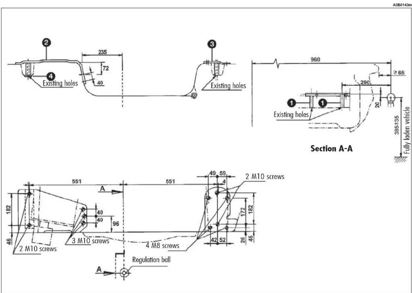
fig. 1
WINTER TYRES
These tyres are specially designed for driving on snow and ice, to be fitted in place of the existing tyres.
Use snow tyres of the same size as the normal tyres provided with the car.
Alfa Romeo Authorized Services will be glad to provide advice concerning the most suitable type of tyre for the customer's requirements.
For the type of tyre to be used, inflation pressures and the specifications of snow tyres, follow the instructions given in chapter "Technical Specifications".
The winter features of these tyres are reduced considerably when the tread depth is below 4 mm. In this case, they should be replaced. Due to the snow tyre features, under normal conditions of use or on long motorway journeys, the performance of these tyres is lower than that of normal tyres.
It is therefore necessary to limit their use to the purposes for which they are certified.
WARNING When snow tyres are used with a max. speed index below the one that can be reached by the car (increased by 5%), place a notice in the passenger compartment, plainly in the driver's view which states the max. permissible speed of the snow tyres (as per EC Directive).
All four tyres should be the same (brand and track) to ensure greater safety when driving and braking and better driveability.
Remember that it is inappropriate to change the direction of rotation of tyres.
text_image
WARNING The max. speed for snow tyres with "Q" marking is 160 km/h, 190 km/h for tyres with "T" marking and 210 km/h for tyres with "H" marking. The Road Traffic Code speed limits must however be always strictly ob- served.SNOW CHAINS
Use of snow chains should be in compliance with local regulations.
Use snow chains with reduced size:
- for tyres 185/65 R15" e 205/60 R15" use snow chains with reduced size with max. protrusion beyond the tyre profile of 12 mm.
— for tyres 205/55 R16" use snow chains with reduced size with max. protrusion beyond the tyre profile of 9 mm.

Tyres 215/45 R17" can not be fitted with snow chains due to interference on suspension support.
Snow chains should only be applied to the driving wheels (front wheels).
Alfa Romeo Authorized Services should first be contacted before purchasing or using snow chains.
Check the tension of the chains after the first few metres have been driven.

Snow chains cannot be fitted to the spare wheel so, if a front (drive) tyre is punctured and chains must be fitted, the rear wheel should be fitted to the front of the vehicle (inflate the tyres to the specified pressure as soon as possible) and the spare tyre should be fitted to the rear. A snow chain can then be safely fitted to the front wheel.


Keep your speed down when snow chains are fitted.
Do not exceed 50 km/h. Avoid potholes, steps and pavements and avoid also to drive for long distances on roads not covered with snow to prevent damaging the car and the roadbed.
VEHICLE INACTIVITY
If the car is to be left inactive for long periods, the following precautions should be noted:
— House the vehicle under cover in a dry and possibly ventilated place.
- Engage a gear.
— Check that the handbrake is not engaged.
— Clean and protect the painted parts using protective wax.
- Disconnect the negative terminal (—) and check the battery charge. This check is to be repeated every three months. Recharge if the optical indicator shows a dark colour without the central green area.
WARNING Where applicable, switch off the electronic car alarm with the remote control.
— Clean and protect the shiny metal parts using special compounds readily available.
— Sprinkle talcum powder on the rubber windscreen and rear window wiper blades and lift them off the glass.
— Slightly open the windows.
— Cover the car with a cloth or perforated plastic sheet. Do not use sheets of non-perforated plastic as they do not allow moisture on the car body to evaporate.
— Inflate the tyres to 0.5 bar above the normal specified pressure and check it at intervals.
— If you don't disconnect the battery from the electric system, check its charge every month and recharge it if the optical indicator shows a dark colour without the central green area.
— Do not drain the engine cooling system.
REMOVING FROM STORAGE
Before using your vehicle after a long period of inactivity, the following operations should first be carried out:
— Do not dust the outside of the vehicle.
— Visually check that there are no leaks (oil, brake and clutch fluid, engine coolant, etc.).
— Replace engine oil and filter.
— Check:
- brake-clutch fluid level
- level of engine coolant fluid.
— Check the air cleaner and replace if necessary.
— Check tyre pressure and ensure that they are not damaged, cracked or cut. If they are they must be replaced.
— Check the state of the drive belts.
— Reconnect the battery negative terminal (—) after checking that the charge is adequate.
— With the gear lever in neutral start the engine and allow the engine to run for a few seconds whilst repeatedly working the clutch pedal.

WARNING
This operation must be performed in the open. The
exhaust gases contain carbon monoxide which is extremely toxic and may also be lethal.
USEFUL ACCESSORIES
In addition to the legal requirements, we recommend keeping the following in the car (fig. 1):
— first aid kit with non-alcoholic base disinfectant, steril gauzes, a roll of gauze, plasters, etc.;
- torch;
— round-ended scissors;
- work gloves.
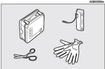
natural_image
Illustration of four different types of cleaning tools: a kit, a battery, a pair of gloves, and a pair of scissors (no text or symbols present)fig. 1
IN AN EMERGENCY
EMERGENCY STARTING
If the Alfa Romeo CODE system is not able to deactivate the engine inhibitor, warning lights 📂 and 🌐 remain lit and the engine cannot be started. To start the engine it is necessary to follow the emergency starting procedure.
WARNING You are advised to carefully read the entire procedure before carrying it out.
If a mistake is made during the emergency procedure, the ignition key should be turned to STOP and the operations must be repeated from the start (point 1).
1) Read the 5-figure electronic code on the CODE card.
2) Turn the ignition key to the MAR position.
3) Fully depress the accelerator pedal and keep it pressed. The warning light will come on for eight seconds approximately and will then go out; now release the accelerator pedal.
4) The warning light begins to flash: after it has flashed for the same number of times as the first digit on the code of the card, press completely and hold down the accelerator pedal until the warning light comes on (for 4 seconds) and then goes out again; now release the accelerator pedal.
5) The warning light will begin to flash: after it has flashed for the same number of times as the second digit on the code of the card, press completely and hold down the accelerator pedal.
6) Repeat this procedure in the same way for the other digits on the CODE card code.
7) After entering the last figure, keep the accelerator pedal pressed. The warning light turns on (for four seconds) and then goes off; now release the accelerator pedal.
8) A quick flash of the warning light (for appr. 4 seconds) confirms that the operation has taken place correctly.
9) Start the car turning the ignition key from the MAR position to the AVV position without returning the key to the STOP position.
Conversely, if the warning light stays on, turn the ignition key to STOP and repeat the procedure starting from point 1.
WARNING After emergency starting it is advisable to turn to an Alfa Romeo Authorized Service, because the procedure described must be repeated each time the engine is started.
STARTING WITH AN AUXILIARY BATTERY
If the battery is flat (for battery with optical hydrometer: dark in colour with no green area in the centre), the engine can be started using another battery of the same or a little higher capacity than the flat one.
This is what you should do fig. 1:
1) Remove the protecting cover on the battery positive pole by pressing the related side wings (front side), then connect the positive terminals (plus sign + next to the terminal) of the two batteries with a special cable.
2) Connect a second cable to the negative terminal (—) of the auxiliary battery with an earth point ↓ on the engine or the gearbox of the car to be started.
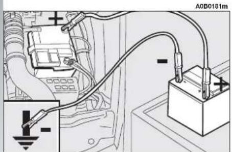
text_image
A0B0181mfig. 1
WARNING Do not directly connect the negative terminals of the two batteries: any sparks may set fire to the gas that may be released from the battery. If the auxiliary battery in installed on another car, no metal part shall accidentally come into contact with this car and the one with the flat battery.
3) Start the engine.
4) When the engine is running remove the cables in reverse order.
If after a few attempts the engine does not start, do not insist but contact Alfa Romeo Authorized Services.

Never use a quick battery charger to start the engine in an emergency as this could damage the electronic systems of your vehicle, particularly the control units which manage the starting and supply functions.

WARNING
This starting procedure must be carried out by qualified personnel as incorrect operations may provoke electrical discharge of great intensity. The liquid contained in the battery is toxic and corrosive. Avoid contact with skin and eyes. Keep naked flame and lighted cigarettes away from the battery. Do not cause sparks.

The battery terminal connecting and disconnecting operations generate current that may cause problems to the car's electronic systems. Therefore, this operation should be carried out by skilled personnel.
STARTING BY INERTIA

Never push, tow or coast start the vehicle. This could cause fuel to flow into the catalyst damaging it irreversibly.

WARNING
Remember that the engine brake and power steering are not operational until the engine is started, therefore, much greater effort than usual is needed on the brake pedal and steering wheel.
IN THE EVENT OF A PUNCTURE
WARNING If the car is equipped with "Fix&Go kit for tyre quick repair", see the instructions contained in the following chapter.
GENERAL INSTRUCTIONS
Wheel changing and correct use of the jack and compact spare wheel call for some precautions as mentioned below.

WARNING
Signal the presence of the stationary vehicle according to the current regulations: hazard warning lights, reflecting triangle, etc.
Any passengers should leave the car and wait for the wheel to be changed out of harm of the traffic. If parked on a slope or uneven road surfaces, place wedges or other suitable devices under the wheels to prevent the car from rolling.
Never start the engine when the car is raised on the jack.
When towing a trailer, always remove the trailer before lifting the car.

WARNING
The spare wheel (for versions/markets where required) is specific to your model of car; do not use it on other models, or use the spare wheel of other models on your car.
Should the type of wheels used be changed (alloy rims instead of steel), it is also necessary to replace the complete kit of fastening bolts with others of suitable size. The compact spare wheel should only be used in an emergency and even then its use should be kept to a minimum. Do not drive at speeds of over 80 km/h.

WARNING
On the compact spare wheel there a sticker with
the main warnings regarding the compact spare wheel use and limitations. The sticker shall never be removed or covered. The sticker bears the following instructions in four languages:
ATTENTION! ONLY FOR TEMPORARY USE! 80 km/h MAX! REPLACE IT AS SOON AS POSSIBLE WITH A STANDARD WHEEL. DO NOT COVER THIS INDICATION.
No wheel cap shall be placed on the compact spare wheel.
The car will handle differently when the spare wheel is fitted. Avoid sudden acceleration or braking, sharp corners and fast bends.

WARNING
The life of the spare wheel is approx. 3,000 km. After
this distance it should be replaced with another of the same type.
Never attempt to fit a traditional tyre to a rim designed for use as compact spare wheel. Have the punctured wheel repaired and replaced as soon as possible.
Two or more compact spare wheels should never be used together.
Do not grease the threads of the bolts before installing them; they might slip out.
The jack only serves for changing wheels on the car with which it is provided or on cars of the same model. It must not be used for other purposes such as for instance raising cars of other models. In no case should it be used for repairs under the vehicle.
The vehicle may fall if the jack is not positioned correctly.
Do not use the jack for higher capacities than stated on its label.

WARNING
Snow chains cannot be fitted to the compact spare wheel, so, if a front wheel is punctured and chains need to be used, the front axle should be fitted with normal wheels and the spare wheel fitted to the rear. In this way, as two normal tyres are fitted to the front of the vehicle, snow chains can be mounted, thereby overcoming an emergency. Absolutely never tamper with the inflation valve.
Do not insert tools of any kind between the rim and the tyre. Routinely check that the pressure of the tyres and of the compact spare wheel is as specified in the "Technical specifications" chapter.
CHANGING A WHEEL
(optional for versions/markets where applicable)
You are informed that:
— The jack mass is 2,100 kg.
— The jack requires no adjustment.
— The jack cannot be repaired, in the event of breakage it must be replaced by another original one.
— No tools other than its operating crank can be fitted to the jack.
To change the wheel proceed as follows:
— Stop the car in such a position that it is not dangerous for the traffic, where it is possible to change the wheel safely. Where possible, park on a level, compact surface.

natural_image
Technical line drawing of a car engine bay with visible internal components (no text or symbols)fig. 1a
— Stop the engine and engage the hand-brake.
— Engage first gear or reverse.
— Lift the boot carpet and hook it as shown in (fig. 1a).
- Loosen the clamping device (handle) (A-fig. 2).
A0B0234m

text_image
Technical diagram of a mechanical assembly with labeled parts A, B, and Cfig. 2
— Take out the tool container (B) and take it near the wheel to be changed.
— Take the spare wheel (C).
— Remove the wheel cap (A-fig. 3) (for versions with steel rims only).
— Loosen the fastening bolts by approx. one turn (B-fig. 4).

text_image
A0B0229m Afig. 3
— Place the jack under the car near the wheel to be changed.
— Work the jack crank (A-fig. 5) to extend it until the groove (B-fig. 6) on the upper part of the jack is correctly inserted on the lower profile of the body (C-fig. 6) at about 40 cm from the profile of the wheelhouse.
— Work the jack and raise the car until the wheel is a few centimetres from the ground.
- Completely unscrew the bolts (B-fig. 4), and remove the wheel.
— Make sure that the contact surfaces of the compact spare wheel with the hub are clean and free of impurities which may later cause the fastening bolts to slacken.
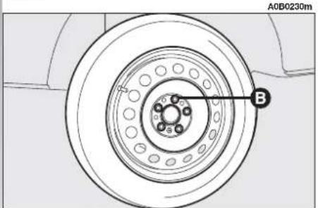
text_image
A0B0230m Bfig. 4
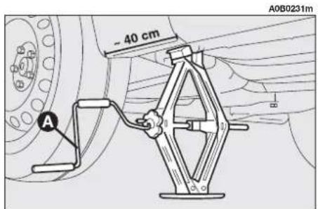
text_image
A0B0231m - 40 cm Afig. 5
— Install the spare wheel by matching one of the holes (A-fig. 7) with the corresponding pin (B-fig. 7).
— Tighten the five fastening bolts.
— Lower the car and remove the jack.
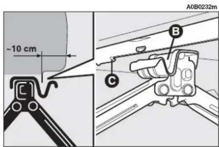
text_image
-10 cm A0B0232m B Cfig. 6
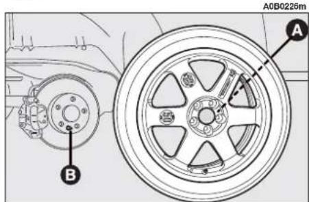
text_image
A0B0226m A Bfig. 7
— Fully tighten the bolts in the sequence shown in fig. 8, without refitting the cap.
REFITTING A NORMAL WHEEL
— Following the procedure described previously, raise the car and remove the spare wheel.
For versions with steel rims:
— Fit a normal wheel bearing in mind that the pin (B-fig.7) must match one of the holes (A-fig.7).
— Make sure that the contact surfaces of the compact spare wheel with the hub are clean and free of impurities which may later cause the fastening bolts to slacken.
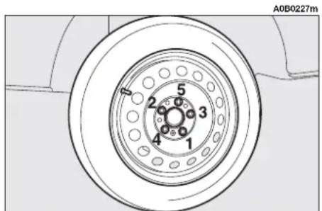
text_image
A0B0227m 1 2 3 4 5 6fig. 8
— Screw the fastening bolts.
— Tighten the bolts following the order previously described for the compact spare wheel fig. 7.
— Place the cap near the wheel so that the inflating valve can come out through the countersunk hole. Press the wheel circumference starting from the area next to the valve countersunk hole until it is completely inserted.
For cars with alloy rims:
— Tighten the pin (A-fig. 9) in one of the fastening bolt holes.
— Fit the wheel on the pin and fasten it with four bolts.
— Remove the centering pin (A-fig. 9) and tighten the last bolt.
— Lower the car and remove the jack; then tighten the bolts as described previously for the spare wheel (fig. 7).
WARNING Incorrect fitting might cause the wheel cap to come off when the car is on the move.
After refitting the wheel:
— stow the spare wheel in the space provided in the luggage compartment;
— insert the jack in its container forcing it lightly to prevent it from vibrating during travelling;
— place the tools used in the housings provided on the support;
— place the tool container on the spare wheel and secure everything with the clamping device (A-fig. 2).

text_image
A0B0228m Afig. 9
FIX&GO KIT
FOR QUICK TYRE
REPAIRING
(for versions/markets where applicable)
The car can be equipped (for versions/markets where applicable) with a tyre quick repairing kit called FIX&GO, replacing the tools and the compact spare wheel usually provided with the car.
The quick repairing kit is placed in the boot inside the appropriate container A-fig. 10.
The quick repairing kit includes fig. 11:
- a tool A to remove the valve body;
-
a compressor B with pressure gauge and fittings;
-
a small cylinder C containing sealer and fitted with a filling pipe, and a sticker bearing the notice "max 80 km/h", to be placed in a position visible to the driver (on the instrument panel) after fixing the tyre;
- a "spout" D to be connected to the filling pipe.

text_image
ALE ROMEO FIX&GO A0B0390mfig. 10

text_image
A0B0332m A B C Dfig. 11
WARNING In the event of a puncture caused by foreign bodies, it is possible to fix tyres having cracks with maximum diameter up to 4 mm.
In fig. 12 it is possible to identify:
A tyre area which can be fixed (holes or cracks with diameter of max 4 mm);
B areas which CANNOT be fixed.
A0B0333m
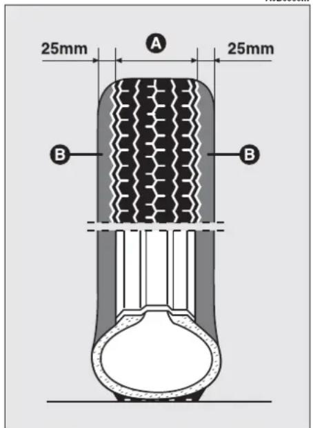
text_image
25mm A 25mm B Bfig. 12

WARNING
It is not possible to fix cracks on the tyre sides
and permanent sealing of cracks on the tread within 25 mm from the tyre side is not guaranteed.

WARNING
Do not use the quick re-pairing kit if the tyre is
damaged due to driving with the wheel flattened. That it is why it is necessary to check accurately the tyre sides.

WARNING
In case of damages to the wheel rim (the deformation
is such that there is an air leakage) or the tyre outside the limit areas previously indicated, fixing is not possible. Do not remove foreign bodies (screws or nails) which have penetrated the tyre.

WARNING
Warning! The small cylinder contains propylene gly- s substance is toxic: do not w it; avoid contact with the skin and the clothes. In contact, rinse with abun- water. If any allergy reaction take place call a medical Keep the small cylinder in appropriate compartment from heat and children.
IT IS NECESSARY TO KNOW THAT:

WARNING
Do not operate the compressor for more than 20
minutes. Risk of overheating.
The sealer included in the quick repairing kit, good for temperatures between -30^ e +80^ , is not adequate for permanent fixing.
The liquid inside the tyre can be easily removed with water.
The sealer has no expire date.
INFLATING PROCEDURE
1) Place the wheel in the position illustrated in the figure (A-fig. 13) for the operation with the valve, then engage the handbrake.
2) Screw the filling pipe (B-fig. 14) to the bottle (C).
3) Unscrew the tyre valve plug, remove the element inside the valve by using the appropriate tool (D-fig. 15); be careful not to place it on the sand or on a dirty surface.
4) Introduce the filling pipe (B-fig. 16) in the tyre valve, keep the bottle (C-fig. 16) with the pipe directed downwards, then press it so that the whole sealer can get into the tyre.
5) Screw again the element inside the valve with the tool (D-fig. 17).
6) Use the appropriate lever (E-fig. 18) to insert and clamp the air compressor pipe (F) to the tyre valve.
7) Start the engine, insert the plug (G-fig. 19) in the lighter (or socket 12V) and inflate the tyre according to the right pressure value (see "Cold inflation pressures" in the "Technical specification" chapter). You are advised to check the tyre pressure value on the pressure gauge (H-fig. 18) with the compressor off, in order to have a more accurate reading.

text_image
A0B0334m Afig. 13
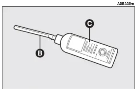
text_image
A0B335m B Cfig. 14
If it is not possible to reach the prescribed pressure, move the car forwards or backwards for about 10 metres, so that the sealer is distributed inside the tyre, then repeat inflation.
If, in spite of the last operation, the prescribed pressure is not achieved, do not move the vehicle and contact Alfa Romeo Authorized Services.
Once the correct tyre pressure has been reached, start driving immediately so that the sealer is distributed evenly inside the tyre.

WARNING
Place the sticker in a position where it can be clearly seen by the driver as a notice that the tyre has been treated with the quick repairing kit. Drive carefully especially in a bend. Do not overcome 80 km/h. Avoid sudden acceleration or braking.
After about 10 minutes, stop and check the tyre pressure once again; remember to engage the handbrake.

WARNING
If the pressure is below 1,3 bars, do not drive any further; FIX & GO cannot guarantee proper hold because the tyre is too much damaged. Contact Alfa Romeo Authorized Services.
Conversely, if at least 1,3 bars are detected, restore the correct pressure (with the engine running and the handbrake engaged) and start driving the car with great care.

text_image
A0B0336m Dfig. 15

text_image
A0B0337m B Cfig. 16

WARNING
If, during the pressure restoring operation, it is not possible to reach at least 1,8 bars, do not drive any further because the tyre is too much damaged and the quick repairing kit cannot guarantee proper hold. Contact Alfa Romeo Authorized Services.

WARNING
Tyres fixed with the quick repairing kit must be used only temporarily.
Drive carefully to the nearest Alfa Romeo Authorized Service to check the tyre conditions, then have it fixed or replaced.
It is absolutely necessary to communicate that the tyre has been fixed with the quick repairing kit.

text_image
A0B0338m Dfig. 17

text_image
A0B0339m E F Hfig. 18
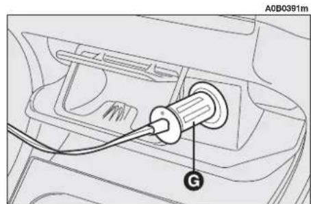
text_image
A0B0391m Gfig. 19
WHEN NEEDING TO CHANGE A BULB

WARNING
Alterations or repairs to the electric system not car-
ried out correctly and without taking into account the specifications of the system may cause malfunctioning and the risk of fire.

WARNING
Halogen bulbs must be handled touching only the
metallic part. If the transparent bulb is touched with the fingers its lighting intensity is reduced and the life of the bulb may be compromised. If touched accidentally, rub the bulb with a cloth moistened with methylated spirits and allow to dry.

WARNING
Possible replacement of a light on vehicles equipped
with Xeno lamps must be carried out by Alfa Romeo Authorized Services.

WARNING
Where possible the bulbs should be replaced by Alfa
Romeo Authorized Services. The correct operation and positioning of the external lights are vital to the safety of the vehicle and its passengers and the subject of specific laws.

WARNING
Halogen bulbs contain pressurised gas, in the case
of breakage they may burst.
GENERAL INSTRUCTIONS
— When a light is not working check the corresponding fuse is intact before replacing the bulb.
— For the location of fuses, refer to the paragraph "In the event of a burnt fuse" in this chapter.
— Before changing a bulb check the contacts for oxidation.
— Burnt bulbs must be replaced with others of the same type and power.
— Always check the height of the headlight beam after changing a bulb to ensure they are safe.
TYPES OF BULBS (fig. 20)
Various types of bulbs are fitted to your vehicle:
A. All glass bulbs
They are pressure-fitted. Pull to remove.
B. Bayonet type bulbs
Press the bulb, turn counter-clockwise to remove this type of bulb from its holder.
C. Tubular bulbs
Free them from their contacts to remove.
D. Halogen bulbs
To remove free it from the clip on its seating.
A0B0233m

text_image
A B C Dfig. 20
| BULBS | FIGURE 20 | TYPE | POWER |
| High beam | D | H1 | 55W |
| Low beam | D | H7 | 55W |
| Front sidelight | B | H6W | 6W |
| Foglight (where required) | D | H1 | 55W |
| Front direction indicator | B | PY21W | 21W |
| Side direction indicator | A | W5W | 5W |
| Rear direction indicator | B | P21W | 21W |
| Stop/side light | B | P21/5W | 21W/5W |
| Additional stop light | B | 3.2W | 3.2 |
| Reversing light | A | P21W | 21W |
| Rear fog guard | B | P21W | 21W |
| Number plate light | B | W5W | 5W |
| Front roof light | A | C10W | 10W |
| Boot light | C | C10W | 10W |
| Rear roof light | C | C5W | 5W |
| Courtesy light (where required) | C | C5W | 5W |
| Glovebox light | C | C5W | 5W |
IF ONE OF THE EXTERNAL LIGHTS GOES OUT

WARNING
Alterations or repairs to the electric system not carried out correctly and without taking into account the specifications of the system may cause malfunctioning and the risk of fire.
WARNING For the type and power of the light refer to what described in the previous chapter "If one of the lights needs to be replaced".
FRONT LIGHT UNITS
The front light units contain the direction indicators, side lights/dipped and main beam light bulbs.
To replace these bulbs the cover must be removed turning counter-clockwise.
The bulbs are arranged inside the light units as follows (fig. 21):
A.Direction indicators
B. Dipped beam headlights
C. Sidelight/main beam headlights.

When the bulbs have been replaced refit the cover in the correct position clockwise and ensuring that into place.
Fig. 22: Dipped beam headlights with Xeno lamp
A. Sidelight/main beam headlights
B. Dipped beam headlights/sidelight.

text_image
A0B0224m A B Cfig. 21

text_image
A B A0B0392mfig. 22
REPLACEMENT OF XENON LIGHTS (optional for versions/markets where applicable)
Xenon lights have a very long life, therefore breakdowns are unlikely.

WARNING
Any operation regarding the front light units must be carried out with the lights turned off and the ignition key removed from the ignition switch: risk of electric discharges.
- Rotate the connector (B-fig. 24) of the Xenon lamp by a quarter of a turn counter-clockwise, as indicated in fig. 25, and remove it.

WARNING
If necessary, have the system checked and repaired only by Alfa Romeo Authorized Services.
Hereafter you find the description of the correct procedure to replace a Xenon light.
Dipped-beam headlamps
To replace the bulb proceed as follows: — Unscrew the three locking screw (B- fig. 23) and remove the protective (A) cover.
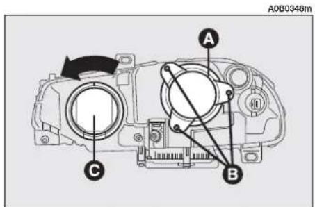
text_image
A0B0348m A B Cfig. 23
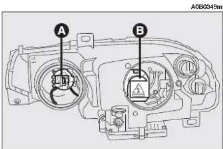
text_image
A0B0349m A Bfig. 24

text_image
A0B0351mfig. 25

The Xenon lamp must be handled touching only the metallic part. If the transparent bulb is touched with the fingers, rub it with a clean cloth moistened with methylated spirits and allow to dry before refitting the bulb.
WARNING Once the operation has been completed, turn dipped beam headlamps on and check that the headlight parabola moves when positioning the light itself. If not, re-engage the lamp.
— Turn ring (A-fig. 26) counter-clock-wise and remove it.
— Remove the Xenon lamp (B-fig. 26).
— Fit the new bulb by placing it so that the notch matches the groove on its housing.
— Refit the protective cover correctly (A-fig. 23).
Main beam headlamps
To replace the bulb proceed as follows:
— Turn the protective cover counter-clockwise (C-fig. 23) in order to reach the high-beam headlight bulb (A-fig. 24).
— Remove connector (A-fig. 27) and remove the bulb operating the clips (B) as shown in the figure.
— Fit the new bulb.
- Refit the protective cover correctly (C-fig. 23).

text_image
A0B0352m A Bfig. 26

text_image
A A0B0350m Bfig. 27

text_image
A0B0354m A Bfig. 28
Direction indicators
To replace the bulb proceed as follows:
— Turn the cover counter-clockwise (A-fig. 29).
— Turn the bulb holder (B) counter-clockwise.
— Remove the bulb from the bulb holder, pushing lightly and turning counter-clockwise.
— Replace the bulb and refit the bulb holder in its housing.
Sidelights
To replace the bulb proceed as follows:
— Turn the protective cover (C-fig. 23) counter-clockwise in order to reach the side-light bulb.
— Remove the bulb (A-fig. 28) from the bulb holder (B), pushing lightly and turning counter-clockwise.
— Replace the bulb and refit the bulb holder (B-fig. 28) in its housing.
- Refit the protective cover correctly (C-fig. 23).
FRONT DIRECTION INDICATORS
To replace the bulb (orange colour), proceed as follows:
— Turn the bulb holder counter-clockwise (A-fig. 30) and remove it.
— Remove the bulb (B-fig. 31) from the bulb holder (A-fig. 31), pushing lightly and turning counter-clockwise.
— Replace the bulb (B-fig. 31).
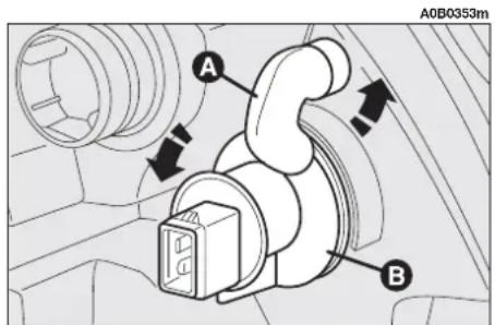
text_image
A0B0353m A Bfig. 29
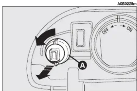
text_image
A0B0225m OFF ON Afig. 30
— Refit the bulb holder (A-fig. 31) by making its notches coincide with the grooves in the headlight unit body and turn it clockwise.
DIPPED-BEAM HEADLAMPS (fig. 32)
To replace the bulb proceed as follows:
— Remove the protective cover
— Disconnect the electrical connector (A).
— Release the bulb catch (B).
— Withdraw the bulb and replace it.
— Fit the new bulb making the tabs of the metallic part coincide with the grooves in the headlamp parabola and hook the bulb catch (B).
— Reconnect the electrical connector (A).
— Refit the protective cover correctly.

text_image
A0B0221m A Bfig. 31
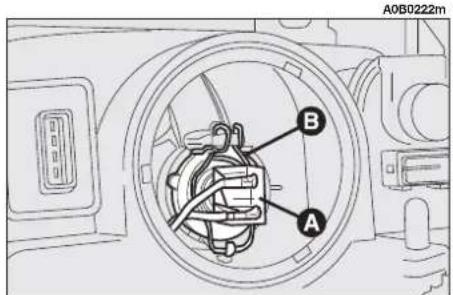
text_image
A0B0222m A Bfig. 32
FRONT FOG LIGHTS (where required)
To replace the bulb proceed under the car as follows:
— Disconnect the connector (A-fig. 33) from the light unit.
— Turn the cover counter-clockwise (B-fig. 33) and remove it.
— Withdraw the supply cable terminal (C-fig. 34).
— Release the bulb stopper (D-fig. 34) and remove the bulb.
— Fit a new bulb making the tabs of the metallic part coincide with the grooves in the lamp lens and hook the bulb stopper (D-fig. 34).
— Re-connect the supply cable terminal (C-fig. 34).
— refit the cover (B-fig. 33) and connect the connector (A-fig. 33) to the light unit.

To adjust the front fog- lights contact Alfa Romeo Authorized Services.

WARNING
The efficiency of the lights will be decreased and may inconvenience other road users if the light units are not correctly adjusted. If in doubt contact Alfa Romeo Authorized Services to have them checked and adjusted if necessary.

text_image
A0B0215m A Bfig. 33

text_image
A0B0216m D Cfig. 34
FRONT SIDELIGHTS
To replace the bulb proceed as follows:
- Remove the protective cover (A-fig. 35).
— Remove the bulb holder (B-fig. 35) which is snap-fitted.
— Remove the bulb (C-fig. 36) from the bulb holder, pushing lightly and turning counter-clockwise.
— Replace the bulb and refit the bulb holder (B-fig. 36) in its housing. - Refit the protective cover correctly (A-fig. 35).
MAIN-BEAM HEADLAMPS (fig. 37)
To replace the bulb proceed as follows:
— Remove the protective cover.
— Release the clip holding the bulb (A).
— Withdraw the power supply (B) cable connector.
— Remove and (C) replace the bulb.
— Reconnect the power cable (B) to the bulb.
— Fit the new bulb making the tabs of the metallic part coincide with the grooves in the headlamp parabola.
— Lock the bulb in place with the clip (A).
— Refit the protective cover correctly.

text_image
A0B0217m B Afig. 35
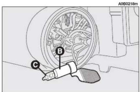
text_image
A0B0218m B Cfig. 36

text_image
A0B0223m C B Afig. 37
SIDE DIRECTION INDICATORS
To replace the bulb proceed as follows:
— Push the transparent cover towards the rear of the car to compress the tab (A-fig. 38). Release the front part and remove the unit.
— Turn the bulb holder counter-clockwise (B-fig. 39) and remove it from the transparent cover (D-fig. 39).
— Withdraw the bulb (C-fig. 39) which is of the pressure-fitted type and replace it.
— Insert the bulb holder (B-fig. 39) in the transparent cover (D-fig. 39) and position the unit ensuring that the clip clicks into place (A-fig. 38).

Take care not to damage the bodywork or the transparent cover when remov-
ing the side direction indicator unit.
REAR LIGHT UNITS
Rear light units contain the reversing lights, rear fog guards, direction indicators, number plate lights, stop/side lights and the additional stop light (3rd stop).
REVERSING LIGHTS AND REAR FOG GUARDS
To replace the bulbs proceed as follows:
- Open the boot.
— Slacken the screws (A or B-fig. 40) fastening the boot trim in correspondence with the light concerned.
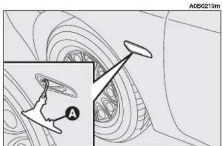
text_image
A0B0219m Afig. 38
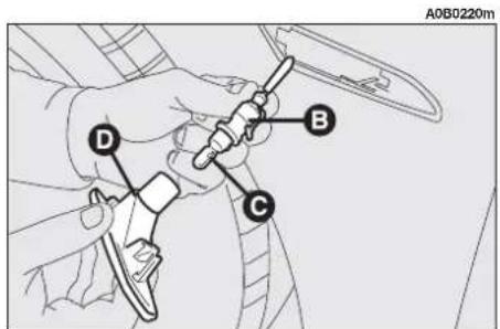
text_image
A0B0220m D B Cfig. 39

text_image
A0B0211m A Bfig. 40
— Lower the boot lid trim in the corresponding area and remove the bulb holder unit (C-fig. 41) releasing the retainer tab (B-fig. 41).
— Remove and replace the spherical type bulb with bayonet attachment pushing it gently and turning counter-clockwise (fig. 42):
(D) reversing light bulb
(E) rear fog guard bulb.
— Refit the bulb holder unit fastening it correctly in place with the retainer tabs (B-fig. 41).
— Refit the boot trim fastening it with the screws removed previously.
DIRECTION INDICATORS/ SIDELIGHTS AND STOP LIGHTS
To replace the bulbs proceed as follows:
- Open the boot.
— Slacken the two fastening screws (A-fig. 43) and remove the protective cover (B-fig. 43).
- Withdraw the bulb holder unit (A-fig. 44) releasing the retainer tabs (B-fig. 44).
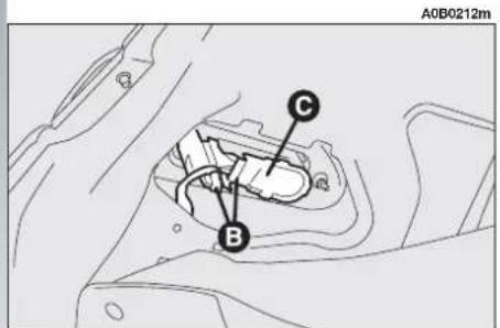
text_image
A0B0212m C Bfig. 41

text_image
A0B0213m D Efig. 42
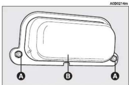
text_image
A0B0214m A B Afig. 43
— Remove and replace the bulb concerned (spherical with bayonet coupling) pushing it gently and turning counter-clockwise (fig. 45).
(C) side light/stop light bulb
(D) direction indicator bulb.
— Refit the bulb holder unit fastening it correctly in place with the retainer tabs (B-fig. 44).
— Refit the protective cover (B-fig. 43) fastening with nuts (A-fig. 43).
NUMBER PLATE LIGHTS
To replace the bulbs proceed as follows:
— Remove the number plate light unit using a flat screwdriver protected by a soft cloth on the stopper (A-fig. 46).
- Remove the unit (B-fig. 46).
— remove the bulb holder (C-fig. 47) turning lightly and replace the bulb (D-fig. 47) which is pressure-fitted.
— Refit the bulb holder (C-fig. 47) turning gently.
— Refit the complete unit (B-fig. 46) firstly inserting the catches and then pressing in correspondence with the stopper (A-fig. 46).

text_image
A0B0209m B Afig. 46

text_image
A0B0207m A Bfig. 44

text_image
A0B0206m D Cfig. 45
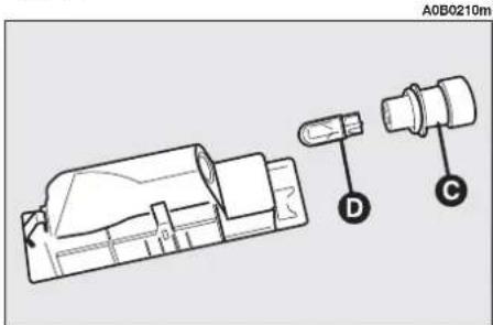
text_image
A0B0210m D Cfig. 47
ADDITIONAL STOP LIGHT (3 ^rd STOP)
To replace the bulbs proceed as follows:
- Open the boot.
— Turn the fastening buttons (A-fig. 48) until they release and lower the trim.
— Slacken the knob (B-fig. 49) and withdraw the complete unit.
— Slacken the screws (C-fig. 50).
- Remove the transparent cover (D-fig. 51) and replace the bulb concerned.
— Refit the transparent cover and install the unit locking it with the knob (B-fig. 49).
— Re-position the trim correctly and fasten with its buttons (A-fig. 48).
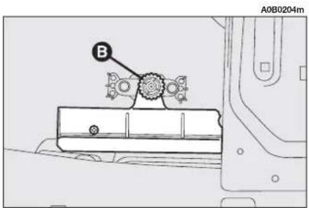
text_image
A0B0204m Bfig. 49
IF ONE OF THE INTERNAL LIGHTS GOES OUT
FRONT ROOF LIGHT
To replace the bulbs proceed as follows:
— Remove the roof light (A-fig. 52) levering in the points shown by the arrows.
- Open the cover (B-fig. 53).
- Replace the bulb concerned (C-fig. 53) by pulling it outwards and freeing it from the lateral contacts ensuring that the new bulb is correctly fitted between the contacts.
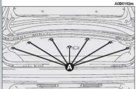
text_image
A0B0192m Afig. 48

text_image
A0B0205m >3km Cfig. 50
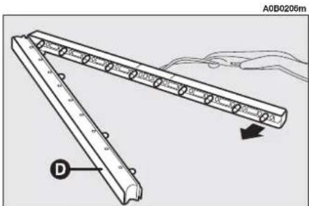
text_image
A0B0206m Dfig. 51
To refit the rooflight reverse the procedure followed for removal.

When refitting the rooflight ensure that the electrical wiring is correct-
ly arranged and does not interfere with the edges of the light or retaining clips.

text_image
A0B0578m Afig. 52
REAR ROOFLIGHT BULBS (except versions with sunroof)
To replace the bulbs proceed as follows:
— Remove the rooflight (A-fig. 54) levering in the point shown by the arrow.
— Remove the bulb (B-fig. 55) pulling outwards and releasing it from the side contacts.
— Fit the new bulb making sure that it is positioned correctly and locked between the contacts.
— Refit the light firstly inserting the side with the connector and then pressing on the other side until the catch clocks into place.
CENTRE REAR ROOF LAMP (only versions with sunroof)
To remove the bulb proceed as follows:
— Remove the roof light (A-fig. 56) levering in the point shown by the arrow.
— Remove the bulb (B-fig. 57) pulling it outwards and releasing it from the side contacts.
— Fit the new bulb making sure that it is positioned correctly and locked between the contacts.
— Refit the roof light firstly inserting the side (C-fig. 57) and then pressing on the other side until the catch clicks into place.

text_image
A0B0201m C Bfig. 53

text_image
A0B0202m Afig. 54

text_image
A0B0203m Bfig. 55
COURTESY LIGHTS (where required)
To remove the bulb proceed as follows:
— Remove the roof light (A-fig. 58) levering in the point shown by the arrow.
— Remove the bulb (B-fig. 59) pulling it outwards and releasing it from the side contacts.
— Fit the new bulb making sure that it is positioned correctly and locked between the contacts.
— Refit the roof light, inserting it in the correct position firstly on one side and then pressing on the other until the tab clicks.

text_image
A0B0196m Afig. 56
A0B0197m

text_image
A0B019/M C Bfig. 57
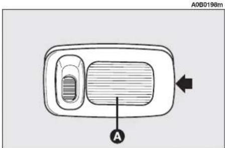
text_image
A0B0198m Afig. 58
GLOVEBOX LIGHT
To remove the bulb proceed as follows:
— Remove the light pushing with a screw-driver on the tab (A-fig. 60).
— Remove the cover (B-fig. 61).
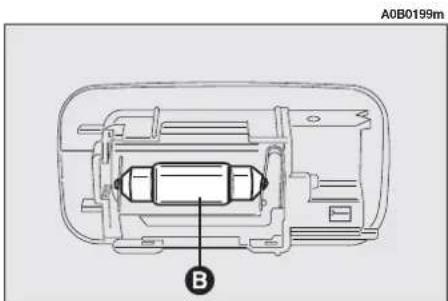
natural_image
Technical diagram of a vehicle chassis inside a housing frame, labeled with component B (no text or symbols beyond label)fig. 59

text_image
A0B0195mfig. 60
— Change the bulb (C-fig. 62) which is pressure-fitted.
- Refit the cover (B-fig. 61).
— Re-install the light inserting it in the correct position firstly on one side and then pushing on the other until the tab clicks.

text_image
A0B0194m Bfig. 61
LUGGAGE COMPARTMENT LIGHT
To remove the bulb proceed as follows:
- Open the boot.
— Turn the fastening buttons (A-fig. 63) until they click and lower the trim.
— Withdraw the clear plastic cover and bulb (A-fig. 64) using a flat-bladed screw-driver.
— Replace the bulb (B-fig. 65) of the cylindrical type pulling it outwards ensuring that the new bulb is correctly positioned between the contacts.
— Refit the transparent cover ensuring that the retaining tabs click into place (C-fig. 65).

text_image
A0B0191m Afig. 64
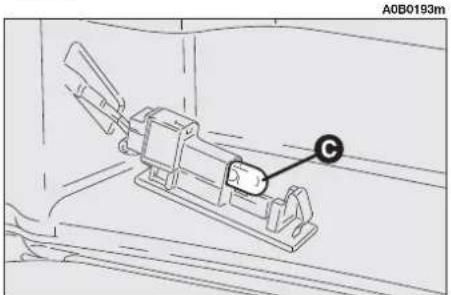
text_image
A0B0193mfig. 62

text_image
A0B0192m Afig. 63

text_image
A0B0190m C B Cfig. 65
IN THE EVENT OF A BURNT FUSE
GENERALITIES
The fuse is (fig. 66) a protective element of the electrical system: basically it operates (i.e. it gets disconnected) in case of breakdown or wrong operation on the system.
When an electrical devices ceases to function, make sure it has not fused. The filament must not be broken: if so, replace the burnt fuse with another of the same value (same colour).
(A) - Intact fuse
(B) - Fuse with broken filament.
Extract the fuse to be replaced using the pincers (C)situated on the fuse box.

Never replace a broken fuse with anything other than a new fuse. Use al-
ways an intact fuse of the same colour.

WARNING
If a main protective fuse (MAXI-FUSE o MEGA-FUSE)
intervenes, do not fix it but contact an Alfa Romeo Authorized Services.

WARNING
Before replacing a fuse check that the key has
been removed from the ignition and that all the services are switched off and/or disengaged.
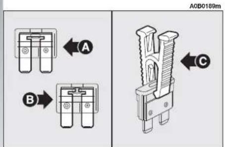
text_image
A0B0189m A B) Cfig. 66

WARNING
Never replace a fuse with another with a higher amp DANGER OF FIRE!

WARNING
If a fuse blows again contact Alfa Romeo Autho-services.
The general protection fuses of Alfa 156 are in the engine compartment, inside a container near the battery positive terminal; to gain access to the fuses lift the two lids (fig. 67 and fig. 68).
FUSE AND RELAYS IN THE MAIN FUSEBOX (fig. 69)
The fuses for the main devices are housed in a control unit under the dashboard, to the left of the steering column.
To gain access to them, remove the panel (A) releasing the tabs (B) in the direction of the arrow below and remove the screw (C).
A. Dipped beam light relay.
B. Relay for sunroof, seat heater, rear window power control, seat electric adjustment.
The symbols that identify the main electric component protected by each fuse, are shown on the label (fig. 70) on the inner side of the panel (A-fig. 69).
Some spare fuses are housed at the right of the control unit (D-fig. 69); you are advised to replenish the stock of spare fuses when they are used.
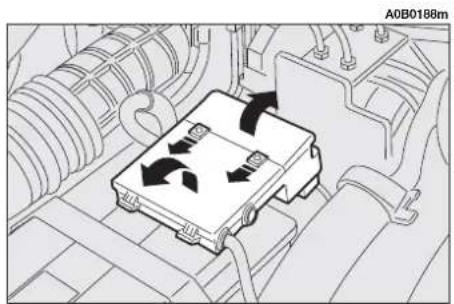
text_image
A0B0188mfig. 67
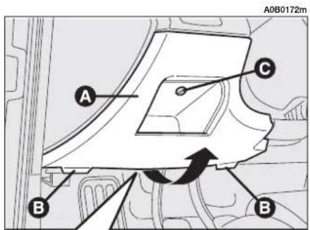
text_image
A0B0172m A C B B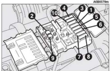
text_image
A0B0579m ① ② ③ ④ ⑤ ⑥ ⑦ ⑧ ⑨ ⑩fig. 68
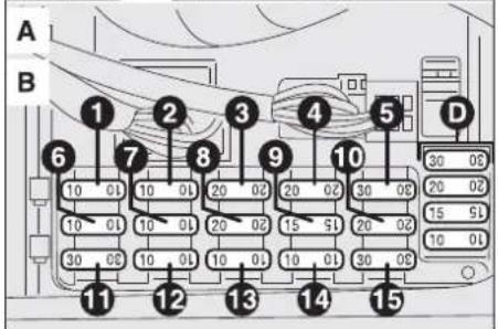
text_image
A B 1 2 3 4 5 6 7 8 9 10 D 30 00 20 00 15 50 10 00 30 00 10 00 20 00 15 50 20 00 10 00 30 00 11 12 13 14 15fig. 69
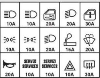 |
fig. 70
FUSES ABOVE THE MAIN FUSEBOX (fig. 71)
The protection fuses of certain devices are grouped together on three containers located above the main fusebox to which access is gained removing the panel (A-fig. 69).
FUSES AND RELAYS ACCESSIBLE FROM THE GLOVEBOX
Some fuses and relays for services supplied on request or only for certain specific market versions are located on a bracket behind the glovebox.
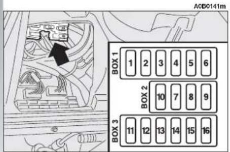
text_image
A0B0141m BOX 1 1 2 3 4 5 6 BOX 2 10 7 8 9 BOX 3 11 12 13 14 15 16fig. 71
To gain access to the fuses remove (A-fig. 72) the pressure-fitted lid.
Access to the relays is gained by removing the glovebox: contact Alfa Romeo Authorized Services.
A. Fog light relay (where required).
B. Headlamp washer timer (where required).
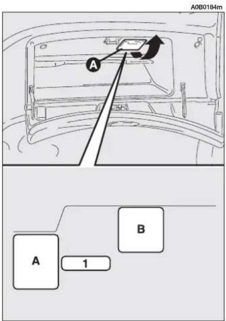
text_image
A0B0184m A A 1 Bfig. 72
FUSES AND RELAYS IN ENGINE BAY
In the engine compartment, housed on a bracket in front of the battery and protected by a special cover, there is a variable number of fuses and relays depending on the versions.
WARNING The arrangement of the fuses and relays may vary depending on the versions and markets. In the event of a suspected anomaly, contact Alfa Romeo Authorized Services.
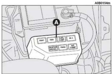
text_image
A0B0154m PAN1 PAN FUEL PART M.J. HLATER DISEL PAN2 AC COMPfig. 73
Remove the cover (A-fig. 73) to gain access to the following relays/fuses (fig. 74):
A. Engine radiator cooling fan 2^nd speed relay (T.SPARK versions).
B. Engine radiator cooling fan 1 ^st speed relay.
C. Fuel pump relay
D. Electronic injection relay
E. Climate control compressor relay
F. Timing variator relay (1.6 T.SPARK only) or engine radiator fan 2 ^nd speed relay (only 2.5 V6 24V, JTD and JTD 16V Multi-jet versions).
G. Fuel oil heater relay (only Diesel versions).

text_image
A0B0183m A B C D G F Efig. 74
For JTD 20v Multijet version refer to fig. 75
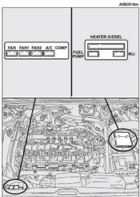
text_image
A0B0618m FAN FAN1 FAN2 A/C COMP HEATER DIESEL FUEL PUMP INJ. 20-fig. 75
For Diesel versions, depending on the options installed, there is a second bracket fastened to the engine compartment rear bulkhead for the following fuses (fig. 76):
A. MAXI-FUSE 30A: additional passenger compartment heater 2^nd level relay.
B. MAXI-FUSE 30A: additional passenger compartment heater 1^st level relay.
WARNING Strictly observe the specified fuse ampere value: in case of doubt, contact Alfa Romeo Authorized Services.

text_image
A 150A 30A B A0B0619mfig. 76
FUSE SUMMARY TABLE
LIGHTS FIGURE AMPERES FUSE
| Left front side light | 7 | 10A | 69 |
| Right front side light | 6 | 10A | 69 |
| Left rear side light | 6 | 10A | 69 |
| Right rear side light | 7 | 10A | 69 |
| Left dipped-beam headlamp/Xenon lamps (optional) | 8 | 20A | 69 |
| Right dipped-beam headlamp/Xenon lamps (optional) | 4 | 20A | 69 |
| Left main-beam headlamp | 2 | 10A | 69 |
| Right main-beam headlamp | 1 | 10A | 69 |
| Cruise Control (optional) | 13 | 10A | 69 |
| Left number plate light | 7 | 10A | 69 |
| Right number plate light | 6 | 10A | 69 |
| Reversing lights/Sound system | 13 | 10A | 69 |
| Left rear fog guard | 7 | 10A | 69 |
| Right rear fog guard | 6 | 10A | 69 |
| Direction indicators - Hazard warning lights | 14 | 10A | 69 |
| Fog lamps | 16 | 15A | 71 |
| Car interior and glovebox lights | 12-13 | 10A | 69 |
| HI-FI BOSE system | 9 | 25A | 71 |
SERVICES FUSE AMPERES FIGURE
| Windscreen wiper, windscreen washer/Rearscreen wiper/Rain sensor (optional) | 10 | 20A | 69 |
| Horns | 11 | 20A | 69 |
| GSM Box for Connect/Navigator-electronic warning system | 13 | 10A | 69 |
| Front power windows | 5 | 30A | 69 |
| Left rear power window | 4 | 20A | 71 |
| Right rear power window | 5 | 20A | 71 |
| Door locking system - Boot light | 3 | 20A | 69 |
| Boot electric opening | 7 | 30A | 71 |
| Rearscreen heating | 15 | 30A | 69 |
| Wing mirror adjustment | 13 | 10A | 69 |
| Wing mirror defrosting | 15 | 30A | 69 |
| Cigar lighter/Odour sensor | 9 | 15A | 69 |
| Headlamp washer | 1 | 20A | 72 |
| Headlamp aiming device | 4 | 10A | 69 |
| Instrument cluster | 12 | 10A | 69 |
| Main-beam headlamp warning light | 2 | 10A | 69 |
| Rearscreen heating warning light | 15 | 30A | 69 |
| Sound system/Diagnosis socket | 12 | 10A | 69 |
| Electronic alarm system | 12 | 10A | 69 |
| Supplementary electrical socket in the boot (Sportwagon versions) | 10 | 20A | 71 |
SERVICES FUSE AMPERES FIGURE
| Remote control | 13 | 10A | 69 |
| Controls lighting/Stop lights | 3 | 10A | 71 |
| Rear control lighting from sidelights | 6 | 10A | 71 |
| Seat heating/Sunroof/Seat electrical adjustment | 8 | 30A | 71 |
| Air bag system | 2 (*) | 10A (*) | 71 |
| ABS system | 9 | 60A | 68 |
| 11 (*) | 10A (*) | 71 | |
| Alfa Romeo CODE system | 13 | 7.5A | 71 |
| Climate control system | 9 | 15A | 69 |
| Engine cooling radiator fan: | |||
| First speed | |||
| -T.SPARK and JTS versions | 6 | 50A | 68 |
| -diesel versions | 6 | 60A | 68 |
| -2.5 V6 24V versions | 6 | 40A | 68 |
| Second speed | |||
| -T.SPARK and JTS versions | 7 | 30A | 68 |
| -diesel versions | 7 | 40A | 68 |
| -2.5 V6 24V versions | 7 | 40A | 68 |
| Passenger compartment fan (petrol versions) | 1 | 40A | 68 |
| Passenger compartment fan (diesel versions) | 4 | 40A | 68 |
| Electronic ignition and injection system | 13 | 7.5A | 71 |
| 14 | 15A | 71 | |
| 15 | 15A | 71 | |
| 5 | 30A | 68 | |
| Glow plugs and resistances on fuel oil filter (diesel versions) | 8 | 70A | 68 |
SERVICES FUSE AMPERES FIGURE
| Fuel oil heater (JTD versions, JTD 16V Multijet) | H | 25A | 74 |
| Services switched off with starting | 1 | 7.5A | 71 |
| Battery power supply for Alfa Romeo CODE/Injection system | 12 | 7.5A | 71 |
| (+15) key-controlled service supply (ignition switch) | 2 | 30A | 68 |
| General service supply (petrol versions) | 4 | 80A | 68 |
| General service supply (diesel versions) | 1 | 80A | 68 |
| General service supply | 3 | 70A | 68 |
| Additional heater (diesel version only) | 10 | 70A | 68 |
| Oil pump supply (Selespeed versions only) | 10 | 30A | 68 |
| Selespeed gearbox(2.0 JTS version) | 7 | 30A | 68 |
| 8 | 20A | 68 | |
| Automatic gearbox(2.5 V6 24V version) | 7 | 40A | 68 |
| 8 | 20A | 68 |
(*) Specific components and values depending on the version/market. If in doubt, especially for the replacement of fuses which protect safety circuits and/or systems (Air bag, ABS, etc.), you are recommended to contact Alfa Romeo Authorized Services, also to locate the cause of the fuse tripping.
IN THE EVENT OF A FLAT BATTERY
First of all, you are advised to refer to the "Car maintenance" chapter for precautions to be adopted in order to prevent the battery from getting flat and to ensure its long durability.
CHARGING THE BATTERY
WARNING The description of the battery charging procedure is described only for informative purposes. This operation should be carried out by Alfa Romeo Authorized Services.
Charging should be slow at a low amp rating for about 24 hours. Charging for a longer time may damage the battery.
Charge the battery as follows:
— Disconnect the terminal from the battery negative (—) pole.
— Connect the charger cables to the battery, respecting polarity.
— Turn on the charger.
— After charging turn off the charger before disconnecting it from the battery.
— Reconnect the terminal to the battery negative (—) pole.

WARNING
The fluid contained in the battery is poisonous and corrosive. Avoid contact with the skin or eyes. The battery should be charged in a well ventilated place and kept away from naked flames or sources of sparks: danger of explosion and fire.

WARNING
Never attempt to charge a frozen battery before thawing it, the danger of explosion exists. If it has frozen, always check that the inside elements are not broken (risk of short circuit) and that the body is not cracked, with the risk of acid coming out which is poisonous and corrosive.
STARTING WITH AN AUXILIARY BATTERY
See "Starting with an auxiliary battery" in this chapter.
IF THE VEHICLE IS TO BE TOWED
The tow ring supplied with the vehicle is housed in the tool box under the boot mat.
To install the tow ring, proceed as follows:
— Take the tow ring from the tool box.
— Remove the cover (A) snap-fitted on the front (fig. 77) or rear bumper (fig. 78). If the supplied flat screwdriver is used to carry out this operation, protect the tip with a soft cloth to prevent damaging the car.
— Firmly screw the ring in its housing.

WARNING
Carefully clean the threaded housing before tightening. Before beginning to use car make sure that the ring is firmly tightened in its bed housing.

text_image
A0B0593m Afig. 77
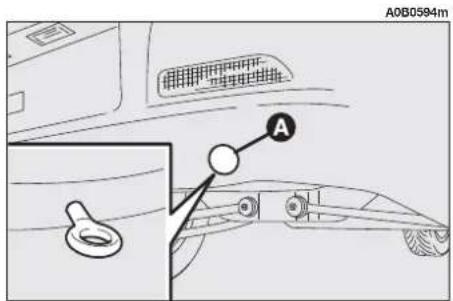
text_image
A0B0594m Afig. 78

WARNING
Before beginning to tow the car, turn the ignition key to MAR and then to STOP, do not remove it. Removing the key automatically engages the steering lock resulting in the impossibility to steer the wheels. When towing remember that without the help of the servo-brake and power steering, it is necessary to exert more effort on the brake pedal and for steering. Do not use flexible cables for towing and avoid jerks. During towing operations make sure that fastening the joint to the car does not damage the components in contact with it. When towing the car it is compulsory to comply with the specific traffic regulations concerning both the towing device and behaviour on the road.
TOWING THE 2.0 JTS SELESPEED VERSION
WARNING For version with Selespeed gearbox, make sure that it is in neutral (N) (checking that the car moves when pushed) and proceed as for towing a normal car with mechanical gearbox following the instructions given on the previous page.
Should it be impossible to set to neutral, do not tow the vehicle; contact Alfa Romeo Authorised Services.

WARNING
Do not start the engine when towing the vehicle.
TOWING THE VERSION WITH AUTOMATIC GEARBOX (2.5 V6 24V Q-SYSTEM)
WARNING For towing the vehicle comply with current local regulations. Also follow the instructions given on the previous page.
If the car needs to be towed, observe the following recommendations:
— if possible, put the car on a rescue vehicle;
— if this is not possible, tow the car raising the driving wheels (front) from the ground;
— if this, too, is not possible, the car may only be towed for 50 Km at a speed of 50 km/h.
The gearshift lever should be at position N for towing.

WARNING
Do not start the engine when the vehicle is being
towed.

The failure to follow the above instructions may cause serious damage to
the automatic gearbox.

Cars with automatic gearbox may be towed only for short distances and at a
low speed: if longer towing is necessary, the driving wheels must be raised to prevent the gearbox from being pulled into rotation during towing.
IF THE VEHICLE IS TO BE LIFTED
USING THE JACK
See paragraph "In the event of a puncture" in this chapter.
You are informed that:
— the jack mass is 2,100 kg;
— the jack requires no adjustment;
— the jack cannot be repaired and in case of breakage it must be replaced by another original one;
— no tool other than its cranking lever may be installed on the jack.

WARNING
The purpose of the jack is only for replacing wheels on the car with which it is provided or on cars of the same model. It must never be used for other purposes such as for example raising cars of other models. In no case must it be used for repairs under the car.

WARNING
The car may fall if the jack is not positioned correctly.
Never use the jack for higher capacities than the one stated on its label.
USING AN ARM LIFT OR WORKSHOP LIFT
The vehicle must only be lifted laterally positioning the ends of the arms or the workshop lift in the areas illustrated, approx. 40 cm from the profile of the wheelhouse (fig. 79).

WARNING
The car is to be lifted positioning the jack or the
workshop lift arm plate only in the points shown (fig. 79).
A0B0588m

text_image
~ 40 cm ~ 40 cmfig. 79
IF AN ACCIDENT OCCURS
— It is important to keep calm.
— If you are not directly involved in the accident, stop at least ten metres away from the accident.
— If you are on a motorway do not obstruct the emergency lane with your car.
— Turn off the engine and turn on the hazard lights.
— At night, illuminate the scene of the accident with your headlights.
— Act carefully, you must not risk being run over.
— Mark the accident by putting the red triangle at the regulatory distance from the car where it can be clearly seen.
— Call the emergency services making the information you give as accurate as you can. On the motorway use the special column-mounted emergency phones.
— In pile-ups on the motorway, particularly when the visibility is bad, there is a high risk of other vehicles running into those already immobile. Get out of the vehicle immediately and take refuge behind the guard rail.
— If the doors are blocked, do not try to get out of the vehicle by breaking the stratified windscreen. The rear and side windows are easier to break.
— Remove the ignition keys of the vehicles involved.
— If you smell petrol or other chemicals, do not smoke and make sure all cigarettes are extinguished.
— Use a fire extinguisher, blanket, sand or earth to put out fires, no matter how small they are. Never use water.
— If it is not necessary to use the lighting system, disconnect the terminal from the battery negative (—) pole.
IF ANYONE IS INJURED
— Never leave the injured person alone. The obligation to provide assistance exists even for those not directly involved in the accident.
— Do not congregate around the injured person.
— Reassure the injured person that help is on its way and will arrive soon. Stay close by to calm him/her down in case of panic.
— Unfasten or cut seat belts holding injured parties.
— Do not give an injured person anything to drink.
— Never move an injured person except in the following cases.
— Pull the injured person from the car only if it risks catching fire, it is sinking in water or is likely to fall over a cliff or similar. Do not pull his/her arms or legs, do not bend the head and, as far as possible, keep the body horizontal.
FIRST-AID KIT
It is advisable to have also a fire extinguisher and a blanket besides the first-aid kit.
CAR MAINTENANCE
PROGRAMMED MAINTENANCE
Correct maintenance is essential for ensuring long car life under the best conditions.
This is why Alfa Romeo has programmed a series of checks and maintenance operations every 20,000 km.
WARNING At 2000 km from the maintenance deadline, the Infocenter display will show "SCHEDULED SERVICE WITHIN" which is shown again turning the ignition key to MAR, every 200 km. For further details, see "Service" in the "Display Infocenter" paragraph in "Getting to know your car" chapter.
It is however wise to remember that Programmed Maintenance does not completely cover all the car's requirements: also in the initial period before 20,000 km service coupon and later, between one coupon and another, ordinary care is still necessary such as for example routinely checking and topping up the level of fluids, checking the tyre pressure, etc...
WARNING The Programmed Maintenance coupons are specified by the Manufacturer. The failure to have them carried out may invalidate the warranty.
The Programmed Maintenance service is carried out by all Alfa Romeo Authorized Services, at pre-established times.
If during each operation, in addition to the ones programmed, the need arises for further replacements or repairs, these may be carried out only with the explicit agreement of the customer.
WARNING You are advised to contact Alfa Romeo Authorized Services in the event of any minor operating faults, without waiting for the next service coupon.
SCHEDULED MAINTENANCE PROGRAMME
20 40 60 80 100 120 140 160 180 Thousands of km
| Check tyre conditions/wear and adjust pressure if necessary | ● | ● | ● | ● | ● | ● | ● | ● | ● |
| Check operation of lighting system (headlights, direction indicators, hazard lights, boot lights, passenger compartment lights, glovebox light, warning lights, etc...) | ● | ● | ● | ● | ● | ● | ● | ● | ● |
| Check operation of windscreen wiper/washer system, adjust spray jets | ● | ● | ● | ● | ● | ● | ● | ● | ● |
| Check position/wear of windscreen/rearscreen wiper blades | ● | ● | ● | ● | ● | ● | ● | ● | ● |
| Check front disk brake pad wear indicator | ● | ● | ● | ● | ● | ● | ● | ● | ● |
| Check conditions of rear disk brake pads | ● | ● | ● | ● | |||||
| Sight check for the conditions of: exterior bodywork, underbody protection, pipes and hoses (exhaust - fuel - brakes), rubber parts (boots - sleeves - bushes - etc.) | ● | ● | ● | ● | ● | ● | ● | ● | ● |
| Check for bonnet and boot lock cleanness, lever cleanness and lubrication | ● | ● | ● | ● | ● | ● | ● | ● | ● |
| Check condition of timing drive belt | ● | ● | |||||||
| Sight check for conditions of Poly-V accessory drive belt | ● | ● | |||||||
| Check/adjust handbrake lever stroke | ● | ● | ● | ● | |||||
| Check/adjust valve clearance (1.9 JTD 8V versions) | ● | ● | ● | ● | ● | ||||
| Check petrol engine exhaust emissions | ● | ● | ● | ● | |||||
| Check engine smoke (diesel versions) | ● | ● | ● | ● | |||||
| Check operation of antievaporation system (petrol engines) | ● | ● |
20 40 60 80 100 120 140 160 180 Thousand of km
| Change fuel filter (diesel versions only) | ● | ● | ● | ● | ● | ● | ● | ● | ● |
| Change air cleaner cartridge (petrol engines) | ● | ● | ● | ● | |||||
| Change air cleaner cartridge (diesel versions only) | ● | ● | ● | ● | ● | ● | ● | ● | ● |
| Check and if necessary top up fluid levels (brakes, hydraulic clutch, power steering, windscreen wiper, battery, engine coolant, etc...) | ● | ● | ● | ● | ● | ● | ● | ● | ● |
| Check and if necessary top up Selespeed oil level (2.0 JTS version) | ● | ● | ● | ● | ● | ● | ● | ● | ● |
| Replacement of timing drive belt (*) and Poly-V accessory drive belt | ● | ||||||||
| Replacement of counter-rotating shaft drive belt (only 2.0 JTS) | ● | ||||||||
| Replacement of spark plugs (T.SPARK 16V, 2.0 JTS and 2.5 V6 24V versions) | ● | ||||||||
| Check operation of engine control systems (through diagnosis) | ● | ● | ● | ● | |||||
| Check gearbox and differential oil level | ● | ● | |||||||
| Check automatic gearbox oil level (2.5 V6 24V version) | ● | ● | ● | ● | ● | ● | ● | ● | ● |
| Change engine oil and oil filter | ● | ● | ● | ● | ● | ● | ● | ● | ● |
| Change brake fluid (or every 2 year) | ● | ● | ● | ||||||
| Replacement of dust/pollen filter | ● | ● | ● | ● | ● | ● | ● | ● | ● |
(*) Or every 3 years in harsh conditions (cold — hot climates, stop and go city traffic, dusty areas or roads covered with sand and/or salt) Or every 5 years, regardless of the mileage.
ANNUAL INSPECTION PROGRAMME
An annual inspection programme has been established for cars that cover less than 20,000 km (e.g. 10,000 km). It consists of the following:
— Check tyre conditions/wear and adjust pressure if required (including the compact spare wheel)
— Check lighting system operation (headlights, direction indicators, hazard lights, boot lights, passenger compartment lights, glovebox light, warning lights of instrument panel, etc.)
— Check windscreen and rear-screen wiper/washer operation, adjust nozzles
— Check windscreen/rear-screen blade position/wear
— Check condition and wear of the front brake pad
— Check for bonnet and boot lock cleanness, lever cleanness and lubrication
— Visually check the following: engine, gearbox, transmission, piping (exhaust - fuel - brakes) rubber components (casings - sleeves - bushings, etc..), brake and fuel hoses
— Check battery charge condition
— Visually check the condition of the belts and various controls
— Check and top up if necessary, the fluid levels (coolant, brake fluid, windscreen washer fluid, battery, etc.)
- Change engine oil
— Replace engine oil filter
— Change pollen filter.
ADDITIONAL OPERATIONS
Every 1000 km or before long journeys check and if necessary top up:
— engine coolant level
- brake fluid/hydraulic clutch control fluid level
— power steering fluid level
— windscreen washer and headlamp washer fluid level
— tyre pressure and conditions.
Every 3000 km check the level of the engine oil and top up if necessary.
You are recommended to use products of the FL Selenia, designed and developed expressly for Alfa Romeo cars (see the table "Specifications of fluids and lubricants" in the "Technical specifications" chapter).
WARNING Engine oil
Should prevailing use of the car be under one of the following specially heavy conditions:
— trailer or caravan towing
— dusty roads
— short distances (less than 7-8 km) repeated and with external temperatures below zero.
— frequently idling engines or long distance low speed driving (e.g. taxis or door-to-door deliveries) or in case of a long term inactivity.
Replace engine oil more frequently than required on SERVICE SCHEDULE.
WARNING Fuel oil filter
The variety of the degree of purity of the fuel oil in commerce may make it necessary to change the fuel oil filter more frequently than stated in the Scheduled Maintenance Programme. If the engine is “sobbing” it is a sign that the filter needs changing.
WARNING Air cleaner
Using the car on dusty roads, change the air cleaner more frequently than stated in the Scheduled Maintenance Programme.
For any doubts about the intervals between engine oil and air cleaner changes in relation to how the car is used, contact Alfa Romeo Authorized Services.
WARNING Battery
You are recommended to have the battery charge conditions checked, preferably at the onset of winter, to avoid the possibility of freezing the electrolyte.
This check should be carried out more frequently if the car is used prevailingly for short journeys, or if it is fitted with services that absorb high amounts of current permanently with the ignition key off, especially if installed in the after market.
In the case of use of the car in hot climates or particularly harsh conditions, it is wise to check the level of the battery fluid (electrolyte) at more frequent intervals than stated in the Scheduled Maintenance Programme.
WARNING Pollen filter
If the car is used frequently in dusty or heavily polluted environments it is advisable to replace the filtering element more frequently; in particular it should be replaced if a reduction of the amount of air admitted to the passenger compartment is noted.

Car maintenance should be entrusted to Alfa Romeo Authorized Services. For routine and minor maintenance operations you wish to carry out yourself, always make sure you have the proper equipment, genuine Alfa Romeo spare parts and the necessary fluids; do not however carry out these operations if you have no experience.
CHECKING FLUID LEVELS

WARNING
Never smoke while working in the engine compartment gas and inflammable gases may be present, with the fire.

When topping up take care not to confuse the various types of fluids: they
are all incompatible with one another and could seriously damage the car.
1 Engine oil - 2 Battery - 3 Brake fluid - 4 Windscreen washer fluid - 5 Engine coolant fluid - 6 Power steering fluid
A0B00174m

text_image
16V TWIN SPARK 2 3 4 5 6fig. 1 - 1.6 T.SPARK, 1.8 T.SPARK versions
A0B00436m

text_image
JTS 18V ① ② ③ ④ ⑤ ⑥fig. 2 - 2.0 JTS version
1 Engine oil - 2 Battery - 3 Brake fluid - 4 Windscreen washer fluid - 5 Engine coolant fluid - 6 Power steering fluid
1 Engine oil - 2 Battery - 3 Brake fluid - 4 Windscreen washer fluid - 5 Engine coolant fluid - 6 Power steering fluid

text_image
V6 24V ① ② ③ ④ ⑤fig. 3 - 2.5 V6 24V version

text_image
A0B00176m 1.9 JTD 2 3 4 5 6fig. 4 - JTD version
A0B00175m
1 Engine oil - 2 Battery - 3 Brake fluid - 4 Windscreen washer fluid - 5 Engine coolant fluid - 6 Power steering fluid
1 Engine oil - 2 Battery - 3 Brake fluid - 4 Windscreen washer fluid - 5 Engine coolant fluid - 6 Power steering fluid

text_image
Alfa Remer 1.9 JTD 16V A0B0558mfig. 5 - JTD 16V Multijet version
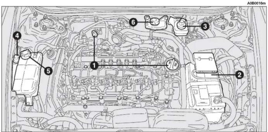
text_image
A0B0616m ① ② ③ ④ ⑤fig. 6 - JTD 20V Multijet version
To improve picture detail, the engine compartment is illustrated without the bonnet
ENGINE OIL
Fig. 7: T.SPARK versions
Fig. 8: 2.0 JTS version
Fig. 9: 2.5 V6 24V version
Fig. 10: JTD versions
Fig. 11: JTD 16V Multijet version
Fig. 12: JTD 20V Multijet version
The engine oil level should be checked when the car is standing on a level surface a few minutes (about 5) after the engine has been switched off.
Remove the dipstick (A), clean it, put it back completely, remove it once again and check that the level is between the MIN and MAX marks on the dipstick.
The interval between the MIN and MAX marks corresponds to approximately 1 liter of oil.

WARNING
When the engine is hot, take care when working inside the engine compartment to avoid burns. Remember that when the engine is hot, the fan may cut in: danger of injury.

WARNING
Scarves, ties and other loose clothing might be by moving parts.

Never add oil with characteristics (classification, viscosity) which are different from those of the oil already in the circuit.
If the oil level is near or even below the MIN, mark, add oil trough the filler neck (B), until reaching the MAX mark.
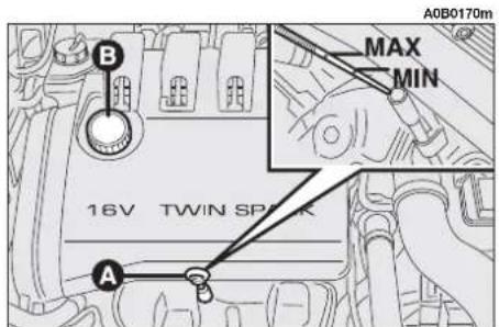
text_image
A0B0170m MAX MIN 16V TWIN SPARK A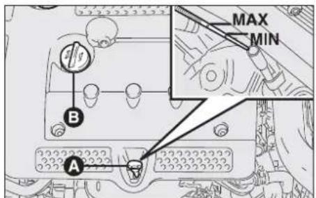
text_image
B A MAX MINfig. 7 - T.SPARK versions fig. 8 - 2.0 JTS version

text_image
MAX MIN A Bfig. 9 - 2.5 V6 24V version
A0B0169mA0B0437m
WARNING If a routine check reveals that the oil level is above the MAX mark, contact Alfa Romeo Authorized Services to have the correct level restored.
WARNING After adding or changing the oil, run the engine for a few seconds and wait a few minutes after stopping it.
Engine oil consumption
Max. engine oil consumption is usually 400 grams every 1000 km.
During the initial period of use the engine settles, therefore the engine oil consumption can only be considered stabilised after the first 5000 ÷ 6000 km.
WARNING Engine oil consumption depends on the way of driving and the conditions of use of the car.

Used engine oil and filter contain pollutants. Contact Alfa Romeo Authorized
Services to have the oil and filter changed as these are equipped to dispose of the waste oil and filters respecting the environment and laws.

text_image
A A0B0165m 100° 100° MAX MINfig. 10 - JTD version

text_image
A0B0559m MAX MIN A Bfig. 11 - JTD 16V Multijet version

text_image
A0B0617m MAX MIN A Bfig. 12 - JTD 20V Multijet version
SELESPEED GEARBOX HYDRAULIC SYSTEM OIL (fig. 13)
The oil level of the Selespeed system should be carried out with the car on a level surface and with the engine stopped and cold.
To check the level, proceed as follows:
— turn the ignition key to MAR;
— disconnect the breather tube and remove the cap (A) checking that the level corresponds with the MAX mark on the dipstick of the actual cap;
— if the level is below the MAX mark, top up with oil until reaching the correct level;
— after screwing the cap back on, insert the breather tube completely on the cap spout and turn the ignition key to STOP.

Do not add oil with different characteristics than those of the oil already in tem.

WARNING
When the engine is hot, take care when working inside the engine compartment to avoid burns. Remember that when the engine is hot, the fan may cut in: danger of injury.

Used gearbox oil contain pollutants. Contact Alfa Romeo Authorized Services to have the oil changed as these are equipped to dispose of the waste oil respecting the environment and laws.
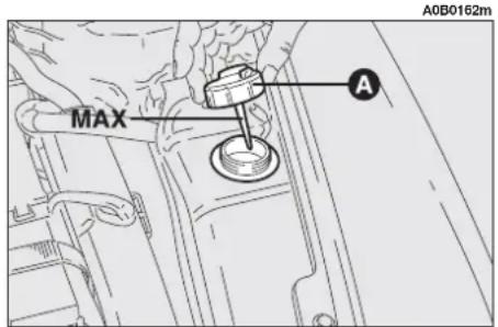
text_image
A0B0162m MAX Afig. 13
Q-SYSTEM AUTOMATIC GEARBOX OIL LEVEL (fig. 14)
The oil should be checked with the engine idling and at operating temperature, the gearshift lever at position P and the car on level ground.
To check the level, proceed as follows:
- remove the dipstick (A);
— clean it with a clean lint free cloth;
— insert the dipstick in its housing pushing well down to the bottom; - remove it to check.
The level should be between the MIN and MAX marks of the sector identified by the word COLD (+40°C).
WARNING After long journeys with the gearbox/differential unit very hot, the oil level should be between the MIN and MAX marks of the sector identified by the word HOT (+80°C).

text_image
WARNING When the engine is very hot, take care when working inside the engine compartment to avoid burns. Remember that when the engine is hot, the fan may cut in: danger of injury.
text_image
MIN MAX MIN MAX A A0B0163mfig. 14
If the oil level is near or below the MIN mark, add TUTELA GI/2 oil through the dipstick housing.
The oil level should never exceed the MAX mark on the dipstick on the COLD side, if the level is checked cold and on the HOT side if the level is checked with the gearbox/differential unit hot.

Do not add oil with different characteristics than those of the oil already in
the system.

WARNING
Used gearbox oil contain pollutants. Contact Alfa
Romeo Authorized Services to have the oil changed as these are equipped to dispose of the waste oil respecting the environment and laws.
ENGINE COOLANT LEVEL

WARNING
Do not remove he cap when the engine is hot: of burns.
Fig. 15: T.SPARK, 2.0 JTS and diesel versions
Fig. 16: 2.5 V6 24V version
The level of the coolant in the header tank (reservoir) should be checked with the engine cold and the car on a level surface and it should be between the MIN and MAX marks on the tank. If the level is low, loosen the header tank cap (A) and slowly pour a mixture of the fluid specified in the "Fluids and lubricants" table in section "Technical Specifications", through the filler neck until nearing the MAX mark; have this operation carried out at Alfa Romeo Authorised Services.
The antifreeze mixture contained in the cooling circuit guarantees protection down to -35^ C.

Top up only with the same fluid contained in the cooling circuit. PARAFLU UP (red) cannot be mixed with PARAFLU 11 (blue) or with other fluids. Should this take place, do not start the engine and contact Alfa Romeo Authorized Service.

The cooling system is pressurised. If necessary, replace the cap only with another genuine one, otherwise system efficiency could be compromised.

text_image
A0B0161m A MAX MINfig. 15 - T.SPARK, 2.0 JTS and JTD versions

text_image
A0B0160m A MAX MINfig. 16 - 2.5 V6 24V version
POWER STEERING OIL LEVEL
Fig. 17: T.SPARK versions
Fig. 18: 2.0 JTS versions
Fig. 19: 2.5 V6 24V and JTD versions
Check that the oil level in the reservoir is at the MAX level.
This operation must be carried out with the car on level ground and when the engine is stationary and cold.
Check that the level reaches the MAX reference notch on the reservoir or coincides with the upper notch (maximum level) on the dipstick integral with the reservoir cap.
If the level of the oil in the reservoir falls below the specified level, top up only with one of the products listed in the table "Fluids and lubricants" in the "Technical specifications" chapter as follows:
— Start the engine and allow the oil in the reservoir to settle.
— When the engine is running turn the steering wheel lock to lock a few minutes.
— Top up to the MAX level notch and then replace the cover.

WARNING
Power steering fluid is highly inflammable. Do not me into contact with hot en- rts.
WARNING Contact Alfa Romeo Authorized Services for maintenance and repair operations.

Oil consumption is very low, if topping up again is needed shortly afterwards,
have the system checked for possible leaks by Alfa Romeo Authorized Services.
A0B0159m
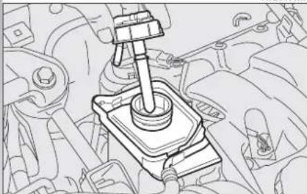
natural_image
Mechanical assembly diagram showing a lever mechanism inside a vehicle engine (no text or labels)fig. 17
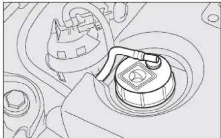
natural_image
Technical line drawing of a mechanical component with no visible text or symbolsA0B0158mA0B0158m

text_image
MAX MINfig. 19fig. 18
BRAKE AND HYDRAULIC CLUTCH FLUID (fig. 20)
From time to time check the instrument panel warning light Ⓚ by pressing cover (B) of the reservoir (A) (with the ignition key at MAR) instrument panel warning light should come on.

When loosening the reservoir cap do not allow the fluid to come into contact
with painted parts. If it does, wash it off immediately with water.

WARNING
Brake and clutch fluid is poisonous and highly corrosive. In the event of accidental contact, wash the parts involved immediately with neutral soap and water, then rinse thoroughly. See a doctor at once if the fluid is swallowed.
WARNING Brake and hydraulic clutch fluid is hygroscopic (i.e. it absorbs moisture). For this reason, if the car is mainly used in areas with a high degree of atmospheric humidity, the fluid should be replaced at more frequent intervals than specified in the Scheduled Maintenance Programme.

WARNING
Symbol Ⓞ on the container indicates synthetic type
brake fluid distinguishing it from the mineral kind. Using mineral type fluids damages the special rubber braking system gaskets beyond repair.

text_image
A0B0157m A B MAXfig. 20
WINDSCREEN/HEADLIGHT WASHER FLUID
Fig. 21: T.SPARK, 2.0 JTS and diesel versions
Fig. 22: 2.5 V6 24V version.
Check the level in the reservoir removing the cap (A).
If necessary top up using a mixture of water and TUTELA PROFESSIONAL SC 35 as follows:
- 30% of TUTELA PROFESSIONAL SC 35 and 70% water in summer;
- 50% of TUTELA PROFESSIONAL SC 35 and 50% water in winter;
- in the case of temperatures below -20^ use TUTELA PROFESSIONAL SC 35 fluid neat.

WARNING
Do not travel with the windscreen washer reser-
voir empty: the action of the wind-screen washer is fundamental for improving vision.

WARNING
Some commercial additives for windscreen washers
are inflammable. The engine compartment contains hot components which could set it on fire.

text_image
A0A0156m Afig. 21
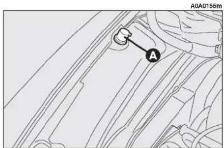
text_image
A0A0155m Afig. 22

To avoid damaging the pump motors, do not use the windscreen washers
when the reservoir is empty.
AIR FILTER
The air cleaner is connected to the temperature and air flow sensors which send the electrical signals needed for correct operation of the injection and ignition system to the control unit.
It must therefore always be in perfect conditions to ensure correct operation of the engine, low consumption and exhaust emission levels.

If they are not carried out correctly and with the due precautions, the operations
involving cleaner replacement described herein may compromise the safety of the car.
This operation should be carried out by Alfa Romeo Authorized Services.

When the car is habitually driven in dusty areas, the cleaner should be at shorter intervals than given in the Programmed Balance Schedule.

Any attempt to clean the air cleaner may cause serious engine damage.
DIESEL FILTER
DRAINING CONDENSATION WATER

Water in the supply circuit can seriously damage the whole injection system and cause malfunctions to engine operation. Should the warning lamp turn on, available for the provided versions/markets, contact as soon as possible the Alfa Romeo Authorised Service for drainage operations.
POLLEN FILTER
This has mechanical/electrostatic air filtering actions, provided that the windows and doors are shut.
Have the pollen filter checked once a year by Alfa Romeo Authorized Services, preferably at the onset of summer.
If the car is mainly used in dusty or heavily polluted areas, the filter should be changed at more frequent intervals than specified in the Scheduled Maintenance Programme.
WARNING The failure to replace the filter can considerably reduce the effectiveness of the climate control system.
BATTERY
The battery is of the "Limited Maintenance" type and is fitted with an optical indicator (A-fig. 23) for checking the electrolyte level and charge.
Under normal conditions of use the electrolyte does not need topping up with distilled water. To make sure that it is in efficient conditions, at routine intervals check the indicator on the battery cover which should be dark in colour with a green central area.
If the indicator is a bright light colour, or dark without the green central area, contact Alfa Romeo Authorized Services.
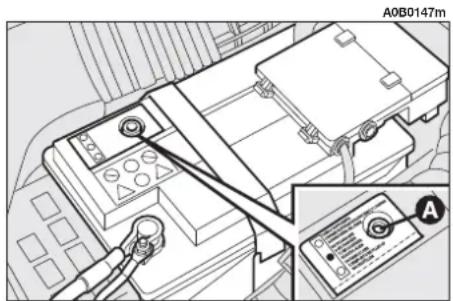
text_image
A0B0147m Afig. 23

Batteries contain sub- stances that are very harmful for the environment. You are advised to have the battery changed at Alfa Romeo Authorized Services, which are properly equipped for disposing of used batteries respecting nature and the law.

WARNING
The liquid in the battery is poisonous and corrosive. Avoid contact with eyes and skin. Do not bring naked flames or possible sources of sparks near to the battery: risk of fire and explosion.

Incorrect fitting of electrical accessories can seriously damage the car. If after buying the car, you wish to install electric accessories (alarm, sound system, radiotelephone, etc.) contact Alfa Romeo Authorized Services who will be able to suggest the most suitable devices and above all advise about the need to use a more powerful battery.

WARNING
When doing any work on the battery or near it, always wear special protective goggles.
CHECKING THE CHARGE
The battery charge may be checked satisfactorily using the indicator, and acting according to the colour the indicator shows.
Refer to the table below or to the label fig. 24 on the battery.

If the car is to remain stationary for a long time in very cold weather, remove the battery and take it to a warm place, otherwise it might freeze.

WARNING
Working with a low fluid level may damage the battery irreversibly, even causing it to burst.
A0B0146m

CARICA SUFFICIENTE / SUFFICIENTLY CHARGED CHARGE SUFFISANTE / AUSREICHEND GELADEN

DA RICARICARE / INSUFFICIENTLY CHARGED A RECHARGER / NICHT AUSREICHEND GELADEN

DA RABBOCCARE / TO BE FILLED UP A REMPLIR / NACHFÜLLEN
fig. 24
CHARGING THE BATTERY
WARNING The description of the battery charging procedure is described only for informative purposes. This operation should be carried out by Alfa Romeo Authorized Services.
Charging should be slow at a low amp rating for about 24 hours. Charging for a longer time may damage the battery.
Charge the battery as follows:
— Disconnect the terminal from the battery negative (—) pole.
WARNING When reconnecting the negative battery cable after having disconnected it, wait for 2 minutes before turning the key to enable the climate control system to reset actuator strokes properly.
— Connect the charger cables to the battery terminals ensuring that the bias is correct.
— Turn on the charger.
— After charging turn off the charger before disconnecting it from the battery.
— Reconnect the battery negative terminal (—).
WARNING If the car is fitted with an alarm system, turn off the alarm with the remote control and deactivate the system turning the emergency key to "OFF" (see "Electronic alarm" in "Getting to know your car" chapter).
| Bright white colour | Top up electrolyte | Contact Alfa Romeo Authorized Services |
| Dark colour without green central area | Low battery charge | Charge the battery (advisable to contact Alfa Romeo Authorized Services) |
| Dark colour with green central area | Electrolyte level and charge sufficient | No action needed |

WARNING
Never attempt to charge a frozen battery before
thawing it, the danger of explosion exists. If it has frozen, always check that the inside elements are not broken and that the body is not cracked, with the risk of acid coming out which is poisonous and corrosive.
WARNING A battery kept at below 50% of its capacity is damaged by sulphation, the capacity is reduced and starting is difficult, there is also more possibility of freezing (this can occur at -10^ ). In the event of a prolonged stop, refer to "Vehicle inactivity", in the chapter "Getting the best out of your car".
REPLACING THE BATTERY
If required, replace the battery with a genuine spare part having the same specifications. If a battery with different specifications is fitted, the service intervals given in the Programmed Maintenance Schedule in this section will no longer be valid. Refer to the instructions provided by the battery manufacturer.
USEFUL HINTS TO EXTEND THE LIFE OF YOUR BATTERY
To avoid quickly draining the battery and to preserve its operating conditions over the course of time, carefully follow the instructions below:
— The terminals must always be tightened.
— As far as possible, avoid keeping services on for a long time with the engine stopped (radio, hazard lights, parking lights, etc.).
— When leaving the car parked in a garage, make sure that the doors, bonnet, boot and interior lids are properly shut to prevent lights from staying on.
— Before doing any work on the electric system, disconnect the battery negative terminal.
— If after purchasing the car, you wish to install electrical accessories which need a permanent electrical supply (alarm, hands-free phone, radio-navigator with satellite anti-theft function, etc.) contact Alfa Romeo Authorized Services whose qualified personnel, in addition to suggesting the most suitable devices from Lineaccessori Alfa Romeo will be able to evaluate the total electrical absorption, checking whether the car's electric system is able to support the load required or whether a battery with higher capacity is necessary. In fact, these devices continue to absorb current with the ignition key off (car parked, engine off) and may gradually drain the battery.
The total absorption of these accessories (standard and installed later) must be less than 0.6 mA x Ah (of the battery), as shown in the table below:
| Battery | Maximum permissible loadless absorption |
| 50 Ah | 30 mA |
| 60 Ah | 36 mA |
| 70 Ah | 42 mA |
You are also reminded that services with high current absorption activated by the user, such as bottle warmers, vacuum cleaners, cellular telephone, mini refrigerator, etc. accelerate the battery drainage process if they are powered with the engine not running or running at idle speed.
WARNING It should also be noted that improper branches on connectors of the electric wiring for installing additional equipment is dangerous, particularly if safety devices are involved.
ELECTRONIC CONTROL UNITS
With normal use of the car, no particular precautions need to be taken.
In the event of work on the electric system or emergency starting, the instructions given below must absolutely be adhered to:
— Always switch off the engine before disconnecting the battery from the electric system.
— If it is necessary to charge the battery, always disconnect it from the electric system.
— When starting in an emergency, only use an auxiliary battery and not a battery charger.
— Check that the bias is correct and that the connections between the battery and the electric system are in efficient conditions.
— Do not connect or disconnect the terminals of the electronic units while the ignition key is at MAR.
— Do not check for current in the cables by short-circuiting the ends.
— If electrical welding is to be carried out on the body of the car, the electronic control units must be disconnected or removed if the work involves the production of high temperatures.

WARNING
Alterations or repairs to the electric system carried
out incorrectly and without taking into account the specifications of the system, may cause operating faults with the risk of fire.
WHEELS AND TYRES
TYRES PRESSURE
Check the pressure of each tyre, including the compact spare wheel, every two weeks and before a long journey.
The pressure should be checked with the tyre rested and cold.
It is normal for the pressure to increase when the car is in use. If you have to check or restore the pressure when the tyres are hot, bear in mind that the pressure should be +0.3 bar compare with the specified rating.
For the correct tyre inflation pressure, see "Wheels" in the "Technical specifications" chapter.

WARNING
Remember that car road holding also depends on correct tyre inflation pressure.
Incorrect pressure causes abnormal tyre wear fig. 25:
A - Normal pressure: tread evenly worn.
B - Low pressure: tread particularly worn at the edges.
C - High pressure: tread particularly worn in the centre.

WARNING
Excessively low pressure causes overheating of the
tyre with the possibility of serious damage to it.
Tyres should be changed when the tread thickness is reduced to 1.6 mm. In any case follow local regulations.
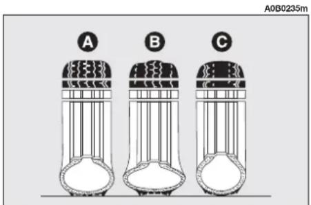
text_image
A0B0235m A B Cfig. 25
WARNINGS
Where possible, avoid sudden braking, tyre squealing starts, etc.
Particularly avoid violent bumps against kerbs, potholes or obstacles of various kinds. Prolonged driving on rough roads may damage the tyres.
Routinely check the tyres for cuts on the sides, swellings or uneven tread wear. If necessary contact Alfa Romeo Authorized Services.
Avoid overloading the vehicle when travelling: this may cause serious damage to the wheels and tyres.
If a tyre is punctured, stop immediately and change it to avoid damage to the tyre, the rim, suspensions and steering system. Tyres age even if they are not used much. Cracks in the tread rubber are a sign of aging. In any case, if the tyres have been on the car for over 6 years, they should be checked by specialised personnel, to see if they can still be used. Also remember to check the spare wheel.
In the case of replacement, always fit new tyres, avoiding those of dubious origin.
Alfa 156 uses Tubeless tyres. Never use an inner tube with these tyres.
If a tyre is changed, also change the inflation valve
To allow even wear between the front and rear tyres, it is advisable to change them over every 10-15 thousand kilometres, keeping them on the same side of the car so as to not reverse the direction of rotation (fig. 26).

WARNING
Do not cross switch the tyres, moving them from
the right of the car to the left and vice versa.

WARNING
Alloy rim painting involving temperatures exceed-
ing 150°C should be avoided since wheel mechanical characteristics could be impaired.
RUBBER HOSES
As far as the brake system and fuel supply rubber hoses are concerned, carefully follow the Scheduled Maintenance Programme of this chapter. Indeed ozone, high temperatures and prolonged lack of fluid in the system may cause hardening and cracking of the hoses, with possible leaks. Careful control is therefore necessary.
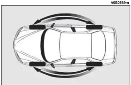
natural_image
Top-down diagram of a car with curved arrows indicating rotational motion (no text or symbols)fig. 26
WINDSCREEN/REAR SCREEN WIPERS
BLADES
Periodically clean the rubber part using special products TUTELA PROFESSIONAL SC 35 is recommended.
If the rubber blades are bent or worn they should be replaced. In any case they should be changed once a year.
A few simple notions can reduce the possibility of damage to the blades:
— If the temperature falls below zero, make sure that ice has not frozen the rubber against the glass. If necessary, thaw using an antifreeze product.
— Remove any snow from the glass: in addition to protecting the blades, this prevents effort on the motor and overheating.
— Do not operate the windscreen and rear window wipers on dry glass.

WARNING
Driving with worn wiper blades is a serious hazard, because visibility is reduced in bad weather.
Changing the windscreen wiper blade (fig. 27)
WARNING The blade on driver's side is fitted with a spoiler that improves adhesion between the blade and the windscreen. To prevent improper fitting, before changing the blade, check the spoiler direction of the blade to be replaced, then fit the new blade following the same spoiler direction.

text_image
A0B0580m B Afig. 27
Proceed as follows:
— Raise the windscreen wiper arm and position the blade so that it forms an angle of 90^ with the arm.
— Press tab (B) of the coupling spring and remove the blade to be replaced from the arm (A).
— When the spring is released from the curved top of the arm, move the blade to allow the arm to be withdrawn through the slot.
— Insert a new blade passing it through the curved top of the arm (A) through the slot.
— Lift the blade to clamp tab (B) of the coupling spring with the curved top of the arm.
— Lower the windscreen wiper arm.
WARNING The blades may differ according to the versions. In any case, follow the instructions provided in the packs available as spares from Alfa Romeo Authorized Services.
SPRAY JETS
Make sure that the windscreen and headlight (where applicable) washer jets deliver a jet of fluid which is adequate and correctly directed.
If the spray devices are not working check that the supply circuit is not blocked. If necessary unblock the nozzles using a needle.
HEADLIGHT WASHERS
(optional for versions/markets where applicable)
Regularly check that the spray jets are intact and clean fig. 28.
If it is necessary to direct the jet, contact an Alfa Romeo Authorized Service.
A0B0581m
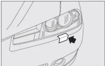
natural_image
Line drawing of a car's front compartment with arrows indicating direction (no text or symbols)fig. 28
BODYWORK
PROTECTION FROM ATMOSPHERIC AGENTS
The main causes of corrosion are:
— atmospheric pollution
— salty air and humidity (coastal areas, or hot humid climates)
— seasonal environment conditions.
Not to be underestimated is also the abrasive action of wind-borne atmospheric dust and sand and mud and gravel raised by other vehicles.
On your Alfa 156, Alfa Romeo has implemented the best manufacturing technologies to effectively protect the bodywork against corrosion.
These include:
— Painting products and systems which give the car particular resistance to corrosion and abrasion.
— Use of galvanised (or pretreated) steel sheets, with high resistance to corrosion.
— Spraying the underbody, engine compartment, wheel arches and other parts with highly protective wax products.
— Spraying of plastic parts, with a protective function, in the more exposed points: underdoor, inner wheel arch linings, edges, etc.
— Use of "open" boxed sections to prevent condensation and pockets of moisture from triggering rust inside.
VEHICLE EXTERIOR AND UNDERBODY WARRANTY
The Alfa 156 is guaranteed against perforation due to rust of any original element of the structure or body. For the general terms of this warranty, refer to the Warranty Booklet.
RECOMMENDATIONS TO PRESERVE THE BODYWORK
Paint
The paintwork does not only serve an aesthetic purpose but also protects the underlying sheet metal.
In the case of deep scrapes or scores, you are advised to have the necessary touching up carried out immediately to avoid the formation of rust.
Only original products should be used for touching up paint (see "Bodywork paint identification label" in the "Technical specifications" chapter).
Normal paint maintenance consists in washing at intervals depending on the conditions and environment of use. For example, in highly polluted areas, or if the roads are sprayed with salt, it is wise to wash the car more frequently.

Detersives pollute water. The car should therefore be washed in areas equipped for the collection and purification of the liquid used in the washing process.
To correctly wash the car:
1) Remove the aerial from the roof to prevent damage to it if the car is washed in an automatic system.
2) Spray the body with a low pressure jet of water.
3) Pass a sponge moistened with a light detergent solution, rinsing the sponge frequently.
4) Rinse well with water and dry with a jet of air or a chamois leather.
When drying, take particular care with the less visible parts like door surrounds, bonnet and around the headlights where water may stagnate. The car should not be taken to a closed area immediately, but left in the open so that residual water can evaporate.
Do not wash the car after it has been left in the sun or with the bonnet hot: this may alter the shine of the paintwork.
Exterior plastic parts must be cleaned in the same way as the rest of the vehicle.
Where possible, do not park under trees; the resinous substance many species release give the paint a dull appearance and increase the possibility of triggering rust processes.
WARNING Bird droppings must be washed off immediately and thoroughly as the acid they contain is particularly aggressive.
Windows
Use specific products to clean the windows. Use clean cloths to avoid scratching or altering the transparency of the glass.
WARNING The inside of the rearscreen should be wiped gently with a cloth in the direction of the filaments to avoid damaging the heating device.
Engine compartment
At the end of the winter the engine compartment should be carefully washed, without directing the jet against electronic control units. Contact a specialised workshop to have this done.

Detergents cause water pollution. Therefore the engine compartment should
be washed in areas equipped for collecting and purifying the liquid used in the washing process.
WARNING The vehicle should washed with the engine cold and the ignition key at STOP. After washing make sure that the various protections (e.g. rubber caps and various covers) have not been damaged or removed.
INTERIOR FITTINGS
Periodically check that water is not trapped under the mats (due to water dripping off shoes, umbrellas, etc.) which could cause oxidisation of the sheet metal.

WARNING
Never use inflammable products like fuel oil ether
or rectified petrol for cleaning inside the car. The electrostatic discharges generated when rubbing to clean may cause fire.
CLEANING SEATS AND FABRIC AND VELVET PARTS
— Use a soft brush or vacuum cleaner to remove dust. Velvet is cleaned better if the brush is moistened.
— Rub the seats with a sponge moistened with a solution of water and neutral detergent.
CLEANING LEATHER SEATS
— Remove dried on dirt with a lightly moistened chamois leather or cloth without pressing too hard.
— Remove liquid or grease stains with a dry absorbent cloth without rubbing. Then wipe with a soft cloth or chamois leather with water and neutral soap. If the stain persists, use specific products, carefully following the instructions for use
WARNING Never use spirit or alcohol-based products.
INTERIOR PLASTIC PARTS
For routine cleaning of interior plastic parts use a soft cloth moistened with water and neutral soap. Remove grease or persisting stains using appropriate solvent-free products designed to preserve appearance and colour of plastic components.
IMPORTANT Never use spirit or petroleum to clean the instrument panel or other plastic parts.

WARNING
Do not keep aerosol cans in the car. There is the risk
they might explode. Aerosol cans must never be exposed to a temperature above 50°C. The temperature inside the car might go well beyond that figure when exposed to the sun's rays.
ALFA 156 SPORTWAGON
In this chapter, you will find all the specific information for Alfa 156 Sportwagon that integrate and complete the previous chapters.
DOORS
REAR DOORS
Opening/closing from outside
— To open the door, only with the inside knob lifted (A-fig. 1), pull the opening handle (B-fig. 2).
— To close, press the knob (A-fig. 1) also with the door open, then shut the door.
Opening/closing from inside

WARNING
Opening the rear doors is only possible if the "child" device is released.
— To open the door pull the handle (A-fig. 3).
— To close it, press the knob (B-fig. 3) also with the door open, then shut the door.
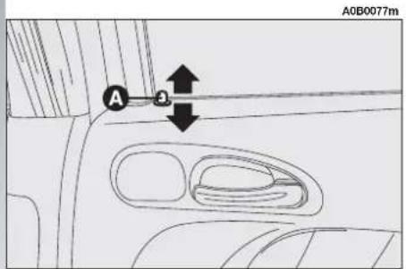
text_image
A0B0077mfig. 1

text_image
A0B0078m Bfig. 2
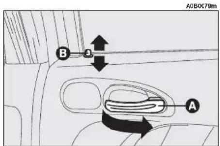
text_image
A0B0079m B Afig. 3
CHILD SAFETY DEVICE (fig. 4)
The rear doors are fitted with a locking device (A) which prevents them from being opened from inside.
WARNING Each device only acts on the door on which it is installed.
The device can only be engaged with the doors open raising or lowering the control with the ignition key.
Position 1 (control up) = Device engaged.
Position 2 (control down) = Device released.
WARNING Also follow the instructions given in the chapter "getting to know your car" under the paragraph "Child safety device".
SEATS
REAR SEAT
Headrest
The car is fitted with two headrests for the side seats (fig. 5). On request for versions/markets where applicable, the car may also be fitted with a third headrest for the central seat (fig. 6).
To pull out the third headrest, push it upwards until hearing the stopping click.
The third headrest (centre) is not removable, whereas the side headrests may be removed as follows:
— Raise the headrests about 2 cm.
— Press the buttons (A and B-fig. 5) at the same time and remove the headrests.
— To refit the headrests keep the buttons pressed (A and B-fig. 5) and insert them completely.
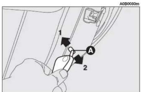
text_image
A0B0080m 1 2 Afig. 4
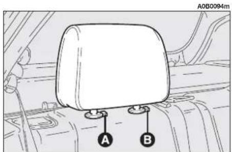
text_image
A0B0094m A Bfig. 5

natural_image
Diagram showing car interior components with a side view of the seatbelt (no text or symbols present)fig. 6

WARNING
Remember that the third headrest (central) should
be pulled out completely so that the nape and not the neck rests on it. Only in this position does it exert its protective action if the car is hit from behind.
Centre armrest (where required)
To use the centre armrest, lower it as illustrated (fig. 7), using the handle (A).
Ski compartment
This compartment can be used for carrying long loads.
To gain access to the compartment lower the armrest, pull the handle (A-fig. 8) and lower the lid on the armrest (fig. 9).
On versions fitted with the third headrest, before lowering the lid on the armrest, lift the headrest completely and set the fabric protection.
On request for versions/markets where applicable, the compartment can be fitted with a bag for carrying skis.
WARNING Lay the bag in the passenger compartment before putting the skis in. After carrying skis, let the bag dry (if wet), then fold it correctly and insert it in the compartment.

WARNING
Always check that the load are anchored properly to
prevent them being thrown against the passengers in case of accident or sharp braking.

text_image
A0B0564mfig. 7

text_image
A0B0097m Afig. 8

natural_image
Line drawing of a car seatbelt with a small rectangular object on the side (no text or symbols)fig. 9
REARSCREEN WIPER - REARSCREEN WASHER
OPERATION (fig. 10)
This is only possible with the ignition key at MAR.
To operate the rearscreen wiper turn the knob (A) to position ☐. The rearscreen wiper works intermittently.
Pushing the lever (B) forwards the rearscreen washer jet comes into operation which is disengaged when the lever is released.
With the rearscreen washer, the wiper comes into operation automatically for a few seconds.
CHANGING THE BLADE (fig. 11)
The rearscreen wiper blade should be replaced together with the arm.
To replace:
— mark the position of the blade in relation to the rearscreen.
— Raise the lid (A), slacken the nut (B) and remove the arm (C).
— Correctly posiiton the new arm and firmly tighten the fastening nut.
— Lower the lid.
SPRAY JET (fig. 12)
If the jet does not spray, check that there is fluid in the windscreen washer reservoir: see the corresponding paragraph in the chapter "Car maintenance". Then check that the holes on the jet (A) are not clogged and free them using a pin, if necessary.

text_image
A0B0081m A Bfig. 10
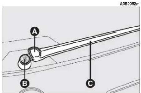
text_image
A0B0082m A B Cfig. 11

text_image
A0B0083m Afig. 12
LUGGAGE COMPARTMENT
The boot lid can be opened from outside the vehicle (pressing the button on the key) and from inside the vehicle.
WARNING If the tailgate is not shut properly, this will be shown by the corresponding warning light △ and warning message on the Infocenter display.
OPENING FROM INSIDE (fig. 13)
To open the tailgate from inside the passenger compartment pull the lever (A) at the side of the driver's seat.

WARNING
Only use the tailgate opening lever with the car sta-
tionary.
Lifting the tailgate is facilitated by the action of the gas springs.

The gas springs are cali-brated to ensure correct lifting of the tailgate with the weights foreseen by the manufacturer. The addition of objects (spoiler, etc.) may adversely affect correct operation and safety in use of the tailgate.
OPENING WITH REMOTE CONTROL (fig. 14)
The boot can be opened by remote control pressing the button (C) on the key, also when the electronic alarm (where fitted) is engaged.
In this case the alarm system switches off volumetric protection and the tailgate control sensor. The system also sounds two beeps and the direction indicators light up for three seconds (with the exception of versions for certain markets).
Closing the boot again the control functions are restored, the system sounds two beeps and the direction indicators light up for three seconds (with the exception of versions for certain markets).
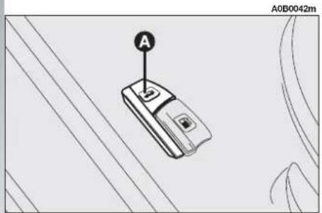
text_image
A A0B0042mfig. 13

text_image
A0B9000m A B C D Efig. 14
CLOSING THE TAILGATE (fig. 15)
To lower the tailgate use the grip (A) on the interior trim.
RESTRAINING THE LOAD (fig. 16-17)
The loads carried can be held in place with the belts hooked to the rings provided at the corners of the boot.
The rings also serve for fastening the luggage retainer net (available on request for versions/markets where applicable c/o Alfa Romeo Authorized Services).
CAUTIONS FOR CARRYING LUGGAGE
On versions not fitted with the automatic rear geometry control system, when travelling at night with a load in the boot, it is necessary to adjust the height of the low beams (see "Headlamps" paragraph in the chapter "Getting to know your car"). For correct use of the aiming device, also make sure that the load does not exceed the values given in the same paragraph.

text_image
A0B0084m Afig. 15

text_image
A0B0085mfig. 16

text_image
A0B0086mfig. 17

WARNING
When using the boot, never exceed the maximum permissible loads given in the "Technical specifications" chapter. Also make sure that the items contained in the boot are firmly secured, to prevent them being thrown forward and harming the passengers in the event of abrupt braking.

WARNING
If you want to carry fuel in a reserve can, you should comply with legal regulations, only using a certified can suitably fastened to the load retainer rings at the corner of the boot. However, remember that this increases the risk of fire in the event of an accident.
ODDMENTS COMPARTMENT (fig. 18-19)
On the sides of the boot there are two recesses closed by a lid.
To open the cover, press button (A) and turn it downwards. As optional for versions/markets where applicable, the odd-ment compartment on the left-hand side can be provided with CD-Changer.

WARNING
Heavy luggage without restraints could cause serious harm to the passengers in an accident.
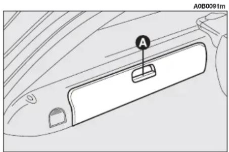
text_image
A0B0091mfig. 18
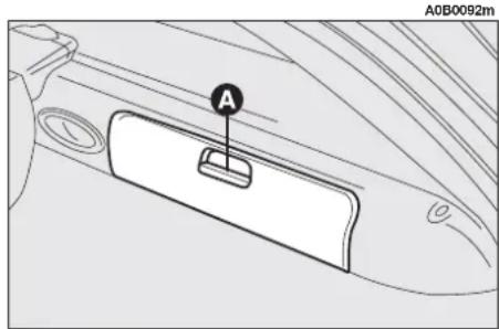
text_image
A0B0092mfig. 19
CURRENT SOCKET (optional for versions/markets where applicable) (fig. 20)
This is on the left-hand side of the boot.
To use the socket, open the lid (A). The socket is supplied with the ignition switch at MAR and can only be used with accessories that absorb a maximum of 15A (power 180W).

Do not connect accessories with higher absorption to the socket. Prolonged current absorption might drain the battery preventing the engine from being started.
OBJECTS RETAINER NET (optional for versions/markets where applicable)
The net can be hooked in different positions (fig. 24-25-26-27) using housings (A and B-fig. 21) provided in the front part of the boot and housings (C and D-fig. 22) in the rear part.
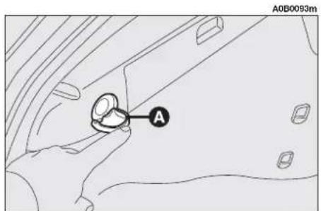
text_image
A0B0093m Afig. 20
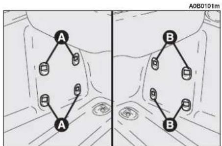
flowchart
graph TD
    A1["A"] --> A2["A"]
    A2 --> A3["A"]
    A3 --> A4["A"]
    A4 --> A5["A"]
    A5 --> A6["A"]
    A6 --> A7["A"]
    A7 --> A8["A"]
    A8 --> A9["A"]
    A9 --> A10["A"]
    A10 --> A11["A"]
    A11 --> A12["A"]
    A12 --> A13["A"]
    A13 --> A14["A"]
    A14 --> A15["A"]
    A15 --> A16["A"]
    A16 --> A17["A"]
    A17 --> A18["A"]
    A18 --> A19["A"]
    A19 --> A20["A"]
    A20 --> A21["A"]
    A21 --> A22["A"]
    A22 --> A23["A"]
    A23 --> A24["A"]
    A24 --> A25["A"]
    A25 --> A26["A"]
    A26 --> A27["A"]
    A27 --> A28["A"]
    A28 --> A29["A"]
    A29 --> A30["A"]
    A30 --> A31["A"]
    A31 --> A32["A"]
    A32 --> A33["A"]
    A33 --> A34["A"]
    A34 --> A35["A"]
    A35 --> A36["A"]
    A36 --> A37["A"]
    A37 --> A38["A"]
    A38 --> A39["A"]
    A39 --> A40["A"]
    A40 --> A41["A"]
    A41 --> A42["A"]
    A42 --> A43["A"]
    A43 --> A44["A"]
    A44 --> A45["A"]
    A45 --> A46["A"]
    A46 --> A47["A"]
    A47 --> A48["A"]
    A48 --> A49["A"]
    A49 --> A50["A"]
    A50 --> A51["A"]
    A51 --> A52["A"]
    A52 --> A53["A"]
    A53 --> A54["A"]
    A54 --> A55["A"]
    A55 --> A56["A"]
    A56 --> A57["A"]
    A57 --> A58["A"]
    A58 --> A59["A"]
    A59 --> A60["A"]
    A60 --> A61["A"]
    A61 --> A62["A"]
    A62 --> A63["A"]
    A63 --> A64["A"]
    A64 --> A65["A"]
    A65 --> A66["A"]
    A66 --> A67["A"]
    A67 --> A68["A"]
    A68 --> A69["A"]
    A69 --> A70["A"]
fig. 21

text_image
A0B0102m C Dfig. 22
To fasten the net, insert the hooks (A-fig. 23) in the housings (B-fig. 23) and push downwards.
To release the net, pull it upwards keeping the connection point pressed (C-fig. 23).
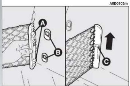
text_image
A0B0103m A B Cfig. 23

natural_image
Top-down diagram of two identical rectangular containers with mesh patterns, placed on a vehicle (no text or symbols)fig. 24

natural_image
Technical line drawing of a mechanical component with textured fill and mounting holes (no text or symbols)fig. 25
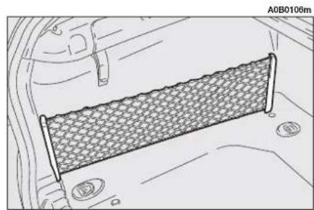
natural_image
Technical line drawing of a mesh fence structure inside a vehicle (no text or symbols)fig. 26

natural_image
Technical line drawing of a mesh-lined panel or mesh structure with no visible text or symbolsfig. 27
LUGGAGE COVER
The luggage cover (A-fig. 28) can be rolled up and removed.
To roll, remove the two rear pins (B-fig. 29) from their housings.
WARNING Accompany the cover when rolling, holding it by the handle (C-fig. 28).
To remove the cover roll it and check that the passenger compartment separation net is also rolled (see following paragraph), then pull the hooks back (A-fig. 30). Raise and remove the cover from the boot.
To put the cover back on, insert the ends of the reel in the respective housings, making sure that the catches are correctly locked forwards making the green symbols at the base of the actual button visible, then pull it by the handle (C-fig. 28) and hook the two rear pins (B-fig. 29).

To avoid damage to the cover do not rest any objects on it.

WARNING
In the event of an accident or abrupt braking any ob- top of the cover might be into the passenger com- nt, with the risk of harming upants; use of the passen- apartment separation net is hended.
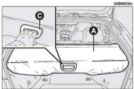
text_image
A0B0603m C Afig. 28

text_image
A0B0109m B Bfig. 29
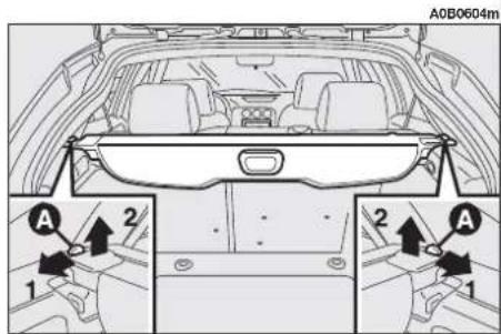
text_image
A0B0604m A 2 1 2 A 1fig. 30
UPPER PASSENGER COMPARTMENT SEPARATION NET (where required) (fig. 31-32)
The upper separation net between the passenger compartment and the boot is contained in the luggage cover reel (A).
To lay the net, remove it from the reel and hook the ends in the two housings (B).
To rewind the net, release the ends from the housings (B) and accompany it as it winds.
LOWER PASSENGER COMPARTMENT SEPARATION NET (fig. 33-34) (optional for versions/markets where applicable)
The lower passenger compartment and boot separation net (A) is contained in the reel fastened under the housing of the luggage cover.
To lay the net remove it from the reel and fasten the hooks (B) to the rings (C).
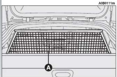
text_image
A0B0111m Afig. 31
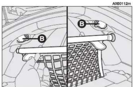
text_image
A0B0112m B Bfig. 32
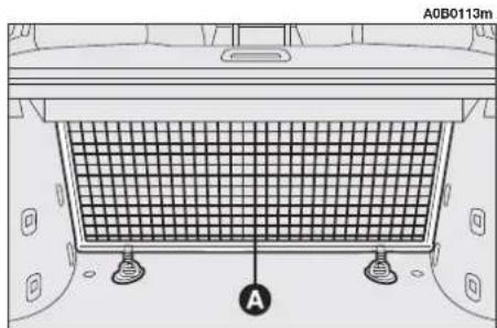
text_image
A0B0113m Afig. 33
To rewind the net, release the hooks (B) from the rings (C) and accompany it while it winds.
EXTENDING THE BOOT
The split rear seat makes partial (1/3 or 2/3) or total extension of the boot possible.
To use the maximum loading volume, remove the luggage cover following the instructions given in the corresponding paragraph.
1/3 Partial extension (fig. 35)
Extension of the left-hand side of the boot makes it possible to carry two passengers on the right-hand part of the rear seat.
2/3 Partial extension (fig. 36)
Extension of the right-hand side of the boot makes it possible to carry one passenger on the left-hand part of the rear seat.

text_image
A0B0114m C B Cfig. 34
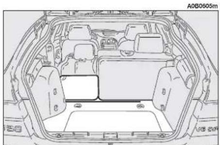
natural_image
Top-down technical drawing of a car interior showing structural components and roof structure (no text or symbols)fig. 35
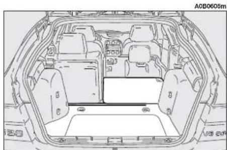
natural_image
Top-down line drawing of a car interior showing structural compartments and storage areas (no text or symbols)fig. 36
Total extension (fig. 37)
Completely folding the rear seat makes the maximum load volume available.
To extend the boot
— Check that the lateral safety belt buckles (A-fig. 38) are located in their pockets on the seat back and that the tab (B-fig. 38) of the central abdominal safety belts is hooked onto the support (C-fig. 38).
— Remove the roll with the luggage cover.
— Tilt the cushions forward pulling from the handle (A-fig. 39) at the centre of each cushion.
— remove the side headrests from the rear seat and insert them in the special housings on the cushions (fig. 40).
— If the car is fitted with the third head-rest from the centre of the seat, lower it completely.
A0B0119m
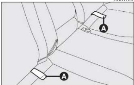
text_image
Diagram showing car seatbelt components with labeled parts A and Bfig. 39

natural_image
Top-down technical drawing of a car interior showing structural components and roof structure (no text or symbols)fig. 37

text_image
A0B0118m A B Cfig. 38

natural_image
Line drawing of a car interior showing the rear seat and backrest (no text or symbols)fig. 40
— Release the seat back catch raising the handle (A-fig. 41) for the right seat back and handle (B-fig. 42) for the left seat back.
— Fold the seat backs forward to obtain a single loading surface with the boot floor.
To take the seats back to the normal position
— Move the seat backs to the vertical position making sure that they are caught correctly.
WARNING The seat backs are correctly caught when the button (A-fig. 43) next to each handle (B-fig. 43) is back in the handle.
— Remove the headrest and tilt the cushion backward, making sure that the safety belts do not remain twisted in the hidden section between the cushion and seat back.
— Refit the headrest on the seat back.
— Refit the roll with the luggage cover.
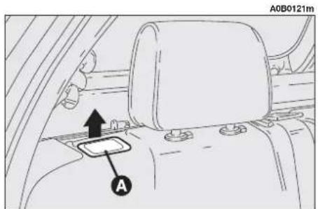
text_image
A0B0121m Afig. 41
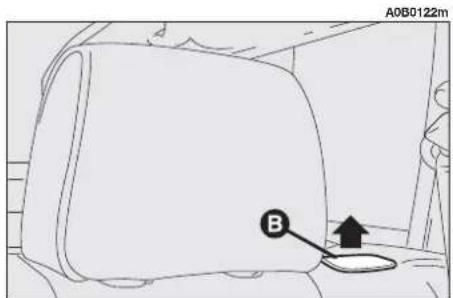
text_image
A0B0122m Bfig. 42
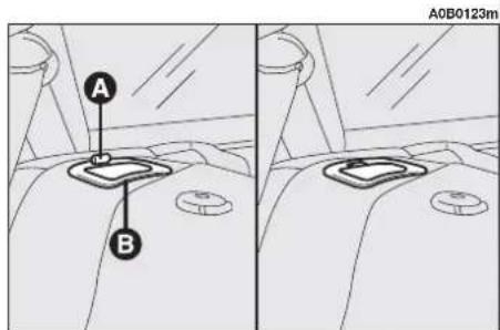
text_image
A B A0B0123mfig. 43
INTERNAL FITTINGS
GRAB HANDLES (fig. 44)
There are two grab handles in correspondence with the front doors.
Two grab handles (A) are located above the rear doors fitted with a coat hook (B).
REFUELLING
EMERGENCY FUEL FLAP OPENING (fig. 45)
If the fuel flap opening lever fails to work, pull the emergency cord (A) on the right-hand side of the boot.
ROOF BARS - SKI RACK
(fig. 46) (optional for versions/markets where applicable)
The car may be fitted with two longitudinal bars that can be used, with the addition of specific accessories, for carrying various items (skis, windsurf boards, etc.).

Never exceed the maximum permissible loads given in the "Technical speci-
fications" chapter.
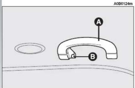
text_image
A0B0124m A Bfig. 44
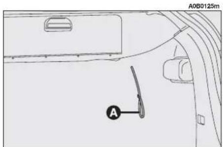
text_image
A0B0125m Afig. 45
natural_image
Line drawing of a car's rear window and roof structure (no text or symbols)fig. 46
SOUND SYSTEM
(optional for versions/markets where applicable)
The fixed sound system, with cassette player (radio with cassette player) or CD player with parametric sound equalizer (radio with CD player) has been designed to suit the specific characteristics of the passenger compartment, with a personalised design that matches the style of the dashboard. The sound system instructions for use are described in the attached supplement.
AUTOMATIC REAR GEOMETRY CONTROL (optional for versions/markets where applicable)
The car is fitted with a semi-bearing hydropneumatic system with built-in self-leveling functions (due to an active element incorporated in the rear shock absorbers) and damping, applied to the rear suspensions instead of conventional shock absorbers.
When the car is loaded with passengers and luggage, the rear geometry lowers in relation to the rigidity of the spring system and the load. However, as soon as the car moves off the system utilises the movements induced on the wheels by the roughness of the road surface to increase its bearing capacity and higher the body up to a pre-established position that will be kept under any load condition.
The distance that must be covered to reach the levelling condition is approx. 2,000 metres and it may vary depending on the road bottom.

WARNING
When using the boot, never exceed the maximum possible loads given in the "fical specifications" chapter. And carried and its arrange- the boot modify road hold-the car in any case even ifometry is kept constant by automatic device.
IN THE EVENT OF A PUNCTURE
WARNING If the car is equipped with "Fix&Go kit for tyre quick repair", see the instructions contained in the "In emergency" chapter.
TOOL AND SPARE WHEEL HOUSING (for versions/markets where required) (fig. 47)
The tools and spare wheels are housed in the boot floor, under the mat. To gain access to them, raise or remove the boot mat using the handle (A-fig. 47).
To take the container with the tools (B) slacken the handle (C).
The spare wheel (D) can be taken after removing the container with the tools.
IF AN EXTERIOR LIGHT GOES OUT
WARNING Before changing a bulb, read the warnings and precautions given in the chapter "In an emergency".
REVERSING LIGHTS AND REAR FOG GUARDS
To change the bulbs (Type B, 21W):
- Open the tailgate.
— Remove the cover (A or B-fig. 48) in correspondence with the light concerned, withdrawing it at the side.
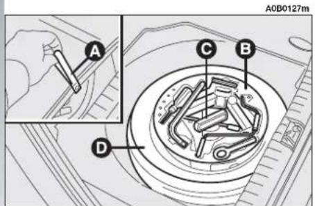
text_image
A0B0127m C B Dfig. 47

text_image
A0B0128m A Bfig. 48
- Remove the bulb holder unit (D-fig. 49) pressing on the retainer tabs (E-fig. 49).
— Remove and replace the bulb concerned (spherical with bayonet coupling) pressing lightly and turning counterclockwise (fig. 50):
(F) reversing light bulb
(G) rear fog guard bulb
— Reinsert the bulb holder unit fitting it correctly between the retainer tabs (E-fig. 49)
— Refit the lid (A or B-fig. 48) inserting it from outside until it fits in.
DIRECTION INDICATORS AND SIDE/STOP LIGHTS
To replace the bulbs (Type B, 21W direction indicators, 5/21W side/stop lights):
— Open the tailgate.
- Slacken the two fastening nuts (A-fig. 51) and remove the protective cover (B-fig. 51).

text_image
A0B0129m D Efig. 49
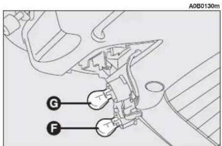
text_image
A0B0130m G Ffig. 50
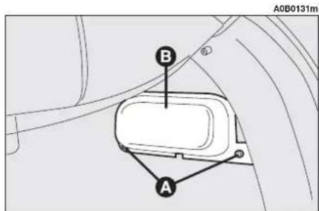
text_image
A0B0131m B Afig. 51
- Remove the bulb holder unit (A-fig. 52) pressing on the retainer tab (B-fig. 52).
— Remove and replace the bulb concerned (spherical with bayonet coupling) pressing lightly and turning counterclockwise (fig. 56):
(C) side light/stop light
(D) direction indicator.
— Reinsert the bulb holder unit fitting the retainer tabs correctly (B-fig. 52).
— Refit the protective cover (B-fig. 51) fastening with nuts (A-fig. 51).
NUMBER PLATE LIGHTS
To replace the bulbs (Type A, 5W):
— Remove the number plate light unit using a flat-tipped screwdriver protected by a soft cloth on the catch (A-fig. 54).
- Remove the unit (B-fig. 54).
— Remove the bulb holder (C-fig. 55) turning clockwise and replace the bulb (D-fig. 55) which snaps on.
— Refit the bulb holder (C-fig. 55) turning clockwise.
— Refit the complete unit (B-fig. 54) firstly inserting the catches and then pressing in correspondence with the stopper (A-fig. 54).
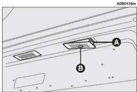
text_image
A0B0134m A Bfig. 54

text_image
A0B0132m A Bfig. 52
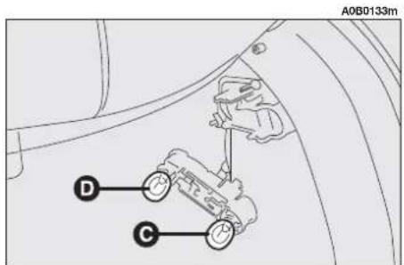
text_image
A0B0133m D Cfig. 53

text_image
A0B0135m C Dfig. 55
ADDITIONAL STOP LIGHTS (3 ^rd STOP)
The additional stop light is built into the rear spoiler (fig. 56).
Refer to the Alfa Romeo Authorized Services for its replacement.
IF AN INTERIOR LIGHTS GOES OUT
WARNING Before changing a bulb, read the warnings and precautions given in the chapter "In an emergency".
TAILGATE LIGHT
To change the bulb (Type C, 10W):
— Open the tailgate.
— Remove the light (A-fig. 57) levering with a flat-tipped screwdriver in the point shown.
— Remove the bulb (B-fig. 58) pulling outwards and releasing it from the side contacts.
— Insert the new bulb fitting it correctly between the contacts.
— Refit the light inserting it and then pressing until the catch clicks into place.

natural_image
Technical line drawing of a mechanical component with no visible text or symbolsfig. 56
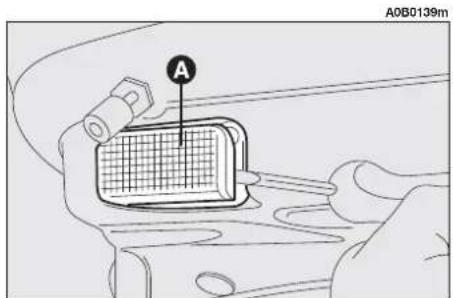
text_image
A0B0139mfig. 57

text_image
A0B0140m Bfig. 58
IF A FUSE BLOWS
The specific fuse for Sportwagon versions is located in the central fuseholder above the main fusebox and access to it is gained removing the protective panel.
WARNING Before changing a fuse or relay, read the warnings and precautions given in the chapter "In an emergency".
System/Component Fuse no. Amperage Location
| Additional current socket in the boot | 10 20A | fig. 59 |
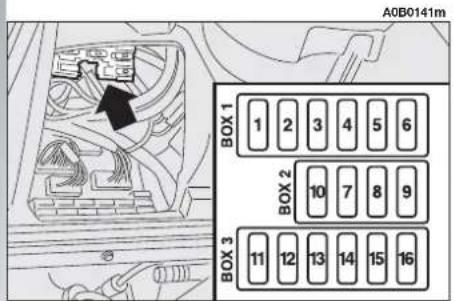
text_image
A0B0141m BOX 1 1 2 3 4 5 6 BOX 2 10 7 8 9 BOX 3 11 12 13 14 15 16fig. 59
TECHNICAL SPECIFICATIONS
IDENTIFICATION DATA
The identification data should be recorded. The identification data is carried on labels located in the following positions (fig. 1-2):
1 - Identification label
2 - Body label
3 - Bodywork paint identification label
- Saloon versions = fig. 1
- Sportwagon versions = fig. 2
4 - Engine label.
BODY LABEL
The body label carrying the following information is located in the engine bay to one side of the right-hand shock absorber upper connection:
— Type of vehicle: ZAR 932000
— Manufacturer's serial number (chassis number).
For some versions/markets the marking is partially covered by a protection. To see the marking completely, remove the cap turning counter-clockwise and raise the protection.
ENGINE LABELS
On the rear left-hand side, gearbox side.
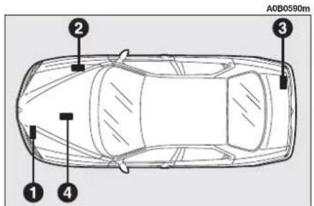
text_image
A0B0590m 1 2 3 4fig. 1

text_image
A0B0056m ③fig. 2
BODYWORK PAINT IDENTIFICATION LABEL
On the Saloon versions, the plate is applied in the internal part of the luggage compartment (3-fig. 1), while on the Sportwagon versions it is applied on the right-hand internal edge of the tailgate (3-fig. 2). The plate carries the following data (fig. 3):
A. Paint manufacturer
B. Name of colour
C. Colour code
D. Colour code for touching up and re-spraying.
IDENTIFICATION LABEL
This is located in the engine bay on the front crossmember (fig. 4).
It carries the following identification data:
A. Space for details of national homologation
B. Space for punching the consecutive chassis number
C. Space available for maximum weights authorised by various national laws
D. Space for version and any supplementary indications to those specified
E. Space for smoke index (diesel versions only)
F. Space for punching manufacturer's name.
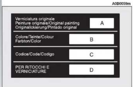
text_image
Verniciatura originale Peinture originale/Original painting Originallickierung/Pintado original A Colore/Teinte/Colour Farbton/Color B Codice/Code/Codigo C PER RITOCCHI E VERNICIATURE D A0B0059mfig. 3

text_image
A0B0076m (F) (A) (B) (C) kg (C) kg (C) kg (C) kg (MOTORE-ENGINE (D) VERSION (D) N° PER RICAMBI (D) N° FOR SPARESfig. 4
ENGINE AND BODY VERSION CODES
| Engine code | Body code | ||
| (Saloon versions) | (Sportwagon versions) | ||
| 1.6 T.SPARK | AR32104 | 932A4100 31L | 932B4100 38H |
| AR32103 (*) | 932A4100 31H (*) | 932B4100 38G (*) | |
| 932A4B00 32F (*) | 932B4B00 39E (*) | ||
| 1.8 T.SPARK | AR32205 | 932A3100 30L | 932B3100 37H |
| 932A3100 30H (*) | 932B3100 37G (*) | ||
| 2.0 JTS | 937A1000 | 932AXA00 52E | 932BXA00 53E |
| 932A2000 (*) | 932AXA00 52D (*) | 932BXA00 53D (*) | |
| 2.0 JTS Selespeed | 937A1000 | 932AXA01 54E | 932BXA01 55E |
| 932A2000 (*) | 932AXA01 54D (*) | 932BXA01 55D (*) | |
| 2.5 V6 24V | AR32405 | 932A1100 26F | 932B1100 33E |
| 2.5 V6 24V Q-System | AR32405 | 932A1101 27F | 932B1101 34E |
| JTD | 937A2000 | 932A2C00 44G | 932B2C00 45F |
| JTD 16V Multijet | 192A5000 | 932AXE00 60E | 932BXE00 61E |
| 937A5000 (**) | 932AXN00 71 (**) | 932BXN00 72 (**) | |
| 937A4000 (*) | 932AXG00 62C (*) | 932BXG00 63C (*) | |
| 192B1000 (*) | 932AXL0066 (*) | 932BXL00 67 (*) | |
| JTD 20V Multijet | 841G000 | 932AXF00 64B | 932BXF00 65C |
| 841M000 | 932AXM00 68 (*) | 932BXM00 69 (*) | |
(*) Version for specific markets
(**) 150 CV version (for versions/markets where applicable)
ENGINE
| 1.6 T.SPARK | 1.8 T.SPARK | 2.0 JTS | 2.0 JTS Selespeed | 2.5 V6 24V | 2.5 V6 24V Q-System | ||
| Code type | AR32104 | AR32205 | 937A1000 | 937A1000 | AR32405 | AR32405 | |
| Cycle | Otto | Otto | Otto | Otto | Otto | Otto | |
| No./position cylinders | 4 in line | 4 in line | 4 in line | 4 in line | 6 in 60^ V | 6 in 60^ V | |
| Piston bore and stroke mm | 82 x 75.65 | 82 x 82.7 | 83 x 91 | 83 x 91 | 88 x 68.3 | 88 x 68.3 | |
| Total displacement | 1598 cm^3 | 1747 cm^3 | 1970 cm^3 | 1970 cm^3 | 2492 cm^3 | 2492 cm^3 | |
| Maximum horsepower (EEC): kW | 88 | 103 | 121 | 121 | 141 | 141 | |
| HP | 120 | 140 | 165 | 165 | 192 | ||
| at rpm | 6200 | 6500 | 6400 | 6400 | 6300 | 6300 | |
| Maximum torque (EEC): | Nm | 146 | 163 | 206 | 206 | 218 | |
| kgm | 14.9 | 16.6 | 21 | 21 | 22.2 | ||
| at rpm | 4200 | 3900 | 3250 | 3250 | 5000 | 5000 | |
| Spark plugs (*) | NGK PFR6B + NGK PMR7A[NGK BKR6EKPA+NGK PMR7A] | NGK PFR6B + NGK PMR7A[NGK BKR6EKPA+NGK PMR7A] | NGK PFR6B[NGK BKR6EKPA] | NGK PFR6B[NGK BKR6EKPA] | NGK R PFR6B | NGK R PFR6B | |
| Fuel | Unleaded petrol95 RON(specification EN228) | Unleaded petrol95 RON(specification EN228) | Unleaded petrol95 RON(specification EN228) | Unleaded petrol95 RON(specification EN228) | Unleaded petrol95 RON(specification EN228) | Unleaded petrol95 RON(specification EN228) | |
| JTD | JTD 16V Multijet | JTD 16V Multijet (**) | JTD 16V Multijet (*) | JTD 16V Multijet (*) | JTD 20V Multijet | JTD 20V Multijet (*) | |
| Code type | 937A2000 | 192A5000 | 937A5000 | 937A4000 | 192B1000 | 841G000 | 841M000 |
| Cycle | Diesel | Diesel | Diesel | Diesel | Diesel | Diesel | Diesel |
| No./position cylinders | 4 in line | 4 in line | 4 in line | 4 in line | 4 in line | 5 in line | 4 in line |
| Piston bore and stroke mm | 82 x 90.4 | 82 x 90.4 | 82 x 90.4 | 82 x 90.4 | 82 x 90.4 | 82 x 90.4 | 82 x 90.4 |
| Total displacement | 1910 cm^2 | 1910 cm^2 | 1910 cm^2 | 1910 cm^2 | 1910 cm^2 | 2387 cm^2 | 2387 cm^2 |
| Maximum horsepower(EEC): kW | 85 | 103 | 110 | 93 | 100 | 129 | 120 |
| HP | 115 | 140 | 150 | 126 | 136 | 175 | |
| at rpm | 4000 | 4000 | 4000 | 4000 | 4000 | 4000 | 4000 |
| Maximum torque (EEC):Nm | 275 | 305 | 305 | 305 | 305 | 385 | 385 |
| kgm | 28 | 31 | 31 | 31 | 39.3 | 39.3 | |
| at rpm | 2000 | 2000 | 2000 | 2000 | 2000 | 2000 | 2000 |
| Fuel | Diesel fuel for motor vehicles(Specification EN590) | Diesel fuel for motor vehicles(Specification EN590) | Diesel fuel for motor vehicles(Specification EN590) | Diesel fuel for motor vehicles(Specification EN590) | Diesel fuel for motor vehicles(Specification EN590) | Diesel fuel for motor vehicles(Specification EN590) | Diesel fuel for motor vehicles(Specification EN590) |
(*) Version for specific markets
(**) For versions/markets where applicable
FUEL SUPPLY
| 1.6 T.SPARK1.8 T.SPARK | 2.0 JTS | 2.0 JTSSelespeed | 2.5 V6 24V | 2.5 V6 24VQ-System | JTDJTD 16VMultijet | JTD 20VMultijet | |
| Supply | ElectronicinjectionMulti Point | Direct injectionBOSCH | Direct injectionBOSCH | ElectronicinjectionMulti Point | ElectronicinjectionMulti Point | Direct injectionBOSCHCOMMON RAIL | Direct injectionBOSCHCOMMON RAIL |
| Firing order | 1-3-4-2 | 1-3-4-2 | 1-3-4-2 | 1-4-2-5-3-6 | 1-4-2-5-3-6 | — | — |
| Injection order | — | — | — | — | — | 1-3-4-2 | 1-24-5-3 |

WARNING
Alterations or repairs to the supply system not carried out correctly or without taking account of the technical specifications of the system, may cause abnormal functioning with the risk of fire.
TRANSMISSION
| 1.6 T.SPARK - 1.8 T.SPARK2.0 JTS | 2.0 JTSSelespeed | 2.5 V6 24V | 2.5 V6 24VQ-System | JTD | JTD 16VMultijet | JTD 20VMultijet | |
| Gearbox | Five forward gearsplus reverse withsynchronisersfor forward speeds | Five forwardgears andreversewithelectroniccontrol | Six forwardgears plusreverse allsynchronised | Four forwardgearsplus reversewithelectroniccontrol | Five forwardgearsplus reverseallsynchronised | Six forwardgearsplus reverseallsynchronised | Six forwardgearsplus reverseallsynchronised |
| Clutch | Dry single diskwith hydraulic control | Drysingle diskwithelectrohydrauliccontrol | Drysingle diskwithhydrauliccontrol | Lock-up | Drysingle diskwith hydrauliccontrol | Drysingle diskwith hydrauliccontrol | Drysingle diskwith hydrauliccontrol |
| Drive | Front | Front | Front | Front | Front | Front | Front |
SPARK PLUG
Clean, intact spark plugs are determinant with regard to engine efficiency and for reducing the emission of pollutants.
If examined by an expert eye, the appearance of a spark plug is a sound clue for locating a fault, even if not involving the ignition system. Therefore if you are experiencing any engine problems, it is important to have the spark plugs checked by Alfa Romeo Authorized Services.

Spark plugs should be replaced at the intervals specified in the Scheduled
Maintenance Programme. Only use spark plugs of the specified type: if the thermal capacity is inadequate or if the envisaged life is not guaranteed inconveniences may ensue.
BRAKES
| 1.6 T.SPARK | 1.8 T.SPARK | 2.0 JTS | 2.0 JTS | 2.5 V6 24V | 2.5 V6 24V | JTD | JTD | 20V | 16V | Multijet | |
| Selespeed | Q-System | JTD | Multijet | ||||||||
| Service brakes:– front– rear | Self-ventilateddisk disk Disk Disk Disk Disk DiskDisk Disk Disk Disk Disk Disk | Self-ventilated | Self-ventilated | Self-ventilated | Self-ventilated | ||||||
| Wheel anti-look system (ABS) with electronic braking distribution.Servo-brake. Electronic control with brake pad wear sensors. Gasket of ecological type. | |||||||||||
| Parking brake | Controlled by hand lever operating rear brakes. | ||||||||||
STEERING
| 1.6 T.SPARK | 1.8 T.SPARK | 2.0 JTS | 2.0 JTS Selespeed | 2.5 V6 24V Q-System | 2.5 V6 24V Multijet | JTD-JTD 16V Multijet | JTD 20V | |
| Type | Rack and pinion.Hydraulic power steering with liquid reservoir in engine compartment | |||||||
| Turning radius (between pavements) | 11.1 m | 11.1 m | 11.1 m | 11.1 m | 11.6 m | 11.6 m | 11.1 m | 11.1 |
WHEELS AND TYRES
| Versions | 1.6 T.SPARK IMPRESSION | 1.6 T.SPARK PROGRESSION | 1.6 T.SPARK DISTINCTIVE | 1.8 T.SPARK IMPRESSION | 1.8 T.SPARK PROGRESSION | 1.8 T.SPARK DISTINCTIVE |
| Standard fittings | ||||||
| Steel wheel Tyres | 6J x 15"185/65 R15" 88H (▼) | 6J x 15"185/65 R15" 88H (▼) | 6J x 15"185/65 R15" 88V (▼) | 6J x 15"185/65 R15" 88V (▼) | ||
| Alloy wheel Tyres | 6,5J x 16"205/55 R16" 91V (●) | 6,5J x 16"205/55 R16" 91V (●) | ||||
| Spare - rim wheel: - tyre | 4J x 15"T125/80 R15" 95M | 4J x 15"T125/80 R15" 95M | 4J x 15"T125/80 R15" 95M | 4J x 15"T125/80 R15" 95M | 4J x 15"T125/80 R15" 95M | 4J x 15"T125 /80 R15" 95M |
| Optional fittings | ||||||
| Alloy wheel Tyre | 6,5J x 15"205/60 R15" 91V (▼) | 6,5J x 15" (□)205/60 R15" 91V (▼) | 6,5J x 15"205/60 R15" 91V (▼) | 6,5J x 15"205/60 R15" 91V (▼) | ||
| Alloy wheel Tyres | 6,5J x 16" (□)205/55 R16" 91V (●) | 6,5J x 16"205/55 R16" 91V (●) | 6,5J x 16"205/55 R16" 91V (●) | 6,5J x 16"205/55 R16" 91V (●) | ||
| Alloy wheel Tyres | 7J x 17"215/45 ZR17 (*) | 7J x 17"215/45 ZR17" (*) | 7J x 17"215/45 ZR17" (*) | 7J x 17"215/45 ZR17" (*) | ||
(^*) = Snow chains may not be used on this tyres
(●) = Tyres on which chains can be fitted: use snow chains with reduced size with max. protrusion beyond the tyre profile of 9 mm.
(▼) = Tyres on which chains can be fitted: use snow chains with reduced size with max. protrusion beyond the tyre profile of 12 mm.
(□) = Excluding Sportwagon versions
Winter tyres: winter tyres with "Q" min. speed index can be used.
| Versions | 2.0 JTS IMPRESSION | 2.0 JTS PROGRESSION | 2.0 JTS DISTINCTIVE | 2.0 JTS Selespeed PROGRESSION | 2.0 JTS Selespeed DISTINCTIVE | 2.5 V6 24V PROGRESSION |
| Standard fittings | ||||||
| Steel wheel Tyres | 6J x 15"185/65 R15" 88V (▼) | 6,5J x 15"205/60 R15" 91V (▼) | 6,5J x 15"205/60 R15" 91V (▼) | 6,5J x 15"205/60 R15" 91W (▼) | ||
| Alloy wheel Tyres | 6,5J x 16"205/55 R16" 91V (●) | 6,5J x 16"205/55 R16" 91V (●) | ||||
| Spare - rim wheel: - tyre | 4J x 15"T125/80 R15" 95M | 4J x 15"T125/80 R15" 95M | 4J x 15"T125/80 R15" 95M | 4J x 15"T125/80 R15" 95M | 4J x 15"T125/80 R15" 95M | 4J x 15"T125 /80 R15" 95M |
| Optional fittings | ||||||
| Alloy wheel Tyre | 6,5J x 15"205/60 R15" 91V (▼) | 6,5J x 15"205/60 R15" 91V (▼) | 6,5J x 15"205/60 R15" 91V (▼) | 6,5J x 15"205/60 R15" 91W (▼) | ||
| Alloy wheel Tyre | 6,5J x 16"205/55 R16" 91V (●) | 6,5J x 16"205/55 R16" 91V (●) | 6,5J x 16"205/55 R16" 91V (●) | 6,5J x 16"205/55 R16" 91V (●) | 6,5J x 16"205/55 R18" 91W (●) | |
| Alloy wheel Tyres | 7J x 17"215/45 ZR17" (*) | 7J x 17"215/45 ZR17" (*) | 7J x 17"215/45 ZR17" (*) | 7J x 17"215/45 ZR17" (*) | 7J x 17"215/45 ZR17" (*) | |
(^*) = Snow chains may not be used on this tyres
(●) = Tyres on which chains can be fitted: use snow chains with reduced size with max. protrusion beyond the tyre profile of 9 mm.
(▼) = Tyres on which chains can be fitted: use snow chains with reduced size with max. protrusion beyond the tyre profile of 12 mm.
Winter tyres: winter tyres with "Q" min. speed index can be used.
| Versions | 2.5 V6 24VQ-SystemPROGRESSION | 2.5 V6 24VQ-SystemDISTINCTIVE | 2.5 V6 24VDISTINCTIVE | JTDIMPRESSION | JTDPROGRESSION | JTDDISTINCTIVE |
| Standard fittings | ||||||
| Steel wheelTyres | 6,5J x 15"205/60 R15" 91W (▼) | 6J x 15"185/65 R15" 88V (▼) | 6J x 15"185/65 R15" 88V (▼) | |||
| Alloy wheelTyres | 6,5J x 16"205/55 R16" 91W (●) | 6,5J x 16"205/55 R16" 91W (●) | 6,5J x 16"205/55 R16" 91V (●) | |||
| Spare wheel:— rim— tyre | 4J x 15"T125/80 R15" 95M | 4J x 15"T125/80 R15" 95M | 4J x 15"T125/80 R15" 95M | 4J x 15"T125/80 R15" 95M | 4J x 15"T125/80 R15" 95M | 4J x 15"T125 / 80 R15" 95M |
| Optional fittings | ||||||
| Alloy wheelTyre | 6,5J x 15"205/60 R15" 91W (▼) | 6,5J x 15"205/60 R15" 91V (▼) | 6,5J x 15"205/60 R15" 91V (▼) | |||
| Alloy wheelTyres | 6,5J x 16"205/55 R16" 91W (●) | 6,5J x 16"205/55 R16" 91W (●) | 6,5J x 16"205/55 R16" 91W (●) | 6,5J x 16"205/55 R16" 91V (●) | 6,5J x 16"205/55 R16" 91V (●) | |
| Alloy wheelTyres | 7J x 17"215/45 ZR17" (*) | 7J x 17"215/45 ZR17" (*) | 7J x 17"215/45 ZR17" (*) | 7J x 17"215/45 ZR17" (*) | 7J x 17"215/45 ZR17" (*) | |
(*) = Snow chains may not be used on this tyres
(●) = Tyres on which chains can be fitted: use snow chains with reduced size with max. protrusion beyond the tyre profile of 9 mm.
(▼) = Tyres on which chains can be fitted: use snow chains with reduced size with max. protrusion beyond the tyre profile of 12 mm.
Winter tyres: winter tyres with "Q" min. speed index can be used.
| Versions | JTD 16V Multijet IMPRESSION | JTD 16V Multijet PROGRESSION | JTD 16V Multijet DISTINCTIVE | JTD 20V Multijet PROGRESSION | JTD 20V Multijet DISTINCTIVE |
| Standard fittings | |||||
| Steel wheelTyres | 6J x 15"185/65 R15" 88V (▼) | 6J x 15"185/65 R15" 88V (▼) | 6,5J x 15"205/60 R15" 91V (▼) | ||
| Alloy wheelTyres | 6,5J x 16"205/55 R16" 91V (●) | 6,5J x 16"205/55 R16" 91V (●) | |||
| Spare wheel:— rim— tyre | 4J x 15"T125/80 R15" 95M | 4J x 15"T125/80 R15" 95M | 4J x 15"T125/80 R15" 95M | 4J x 15"T125/80 R15" 95M | 4J x 15"T125/80 R15" 95M |
| Optional fittings | |||||
| Alloy wheelTyre | 6,5J x 15"205/60 R15" 91V (▼) | 6,5J x 15"205/60 R15" 91V (▼) | 6,5J x 15"205/60 R15" 91V (▼) | ||
| Alloy wheelTyres | 6,5J x 16"205/55 R16" 91V (●) | 6,5J x 16"205/55 R16" 91V (●) | 6,5J x 16"205/55 R16" 91V (●) | 6,5J x 16"205/55 R16" 91V (●) | |
| Alloy wheelTyres | 7J x 17"215/45 ZR17" (*) | 7J x 17"215/45 ZR17" (*) | 7J x 17"215/45 ZR17" (*) | 7J x 17"215/45 ZR17" (*) | |
(^*) = Snow chains may not be used on this tyres
(●) = Tyres on which chains can be fitted: use snow chains with reduced size with max. protrusion beyond the tyre profile of 9 mm.
(▼) = Tyres on which chains can be fitted: use snow chains with reduced size with max. protrusion beyond the tyre profile of 12 mm.
Winter tyres: winter tyres with "Q" min. speed index can be used.
TYRE INFLATION PRESSURES COLD
| Tyres185/65 R15" (▼) | Tyres205/55 R16" (●) | Tyres205/60 R15" (▼) | Tyres215/45 ZR17" (*) | Compact spare wheel125/80 R15" | |||||
| front rear | front rear | front rear | front rear | ||||||
| Reduced load (2 occupants) bar | 2.2 2.2 | 2.4 2.4 | 2.2 2.2 | 2.4 2.4 | 4.2 | ||||
| Full load bar | 2.5 2.5 | 2.6 2.6 | 2.5 2.5 | 2.6 2.6 | |||||
(^*) = Snow chains may not be used on this tyres
(●) = Tyres on which chains can be fitted: use snow chains with reduced size with max. protrusion beyond the tyre profile of 9 mm.
(▼) = Tyres on which chains can be fitted: use snow chains with reduced size with max. protrusion beyond the tyre profile of 12 mm.
With the tyre hot the inflating pressure should be +0.3 bar compared with the specified rating. Recheck pressure value with cold tyres.
With winter tyres the inflation pressure should be +0.2 bar compared with the specified rating.
RIMS AND TYRES
Pressed steel or alloy rims.
Radial Tubeless tyres.
The Log book shows all the homologated tyres.
WARNING In the event of any discrepancies between this Handbook and the vehicle Log Book, only the latter should be considered.
While the specified dimensions remain the same, for driving safety, the vehicle must be fitted with tyres of the same brand and type on all wheels.
WARNING Do not use inner tubes with Tubeless tyres.
CORRECT TYRE READING (fig. 5)
Below are the instructions necessary to know the meaning of the code stamped on the tyre.
The code may be like one of the examples given below.
Example:
205/60 R 15 91V
or:
215/45 ZR 17
205 = Nominal width (S, distance in mm between the sides).
60 = Percentage height/width (H/S) ratio.
R = Radial tyre.
ZR = Radial tyre with speed above 240 kph.
15 = Rim diameter in inches. (Ø).
91 = Load index (capacity), e.g. 91 = 615 kg. Not present in ZR tyres.
V_rZ = Maximum speed index. In ZR tyres the speed index Z is before the R.
Load index (capacity)
| 60 = 250 kg | 84 = 500 kg |
| 61 = 257 kg | 85 = 515 kg |
| 62 = 265 kg | 86 = 530 kg |
| 63 = 272 kg | 87 = 545 kg |
| 64 = 280 kg | 88 = 560 kg |
| 65 = 290 kg | 89 = 580 kg |
| 66 = 300 kg | 90 = 600 kg |
| 67 = 307 kg | 91 = 615 kg |
| 68 = 315 kg | 92 = 630 kg |
| 69 = 325 kg | 93 = 650 kg |
| 70 = 335 kg | 94 = 670 kg |
| 71 = 345 kg | 95 = 690 kg |
| 72 = 355 kg | 96 = 710 kg |
| 73 = 365 kg | 97 = 730 kg |
| 74 = 375 kg | 98 = 750 kg |
| 75 = 387 kg | 99 = 775 kg |
| 76 = 400 kg | 100 = 800 kg |
| 77 = 412 kg | 101 = 825 kg |
| 78 = 425 kg | 102 = 850 kg |
| 79 = 437 kg | 103 = 875 kg |
| 80 = 450 kg | 104 = 900 kg |
| 81 = 462 kg | 105 = 925 kg |
| 82 = 475 kg | 106 = 950 kg |
| 83 = 487 kg |

text_image
A0B0395m S H Ø ① ② ③fig. 5
Maximum speed index
Q = up to 160 km/h.
R = up to 170 km/h.
S = up to 180 km/h.
T = up to 190 km/h.
U = up to 200 km/h.
H = up to 210 km/h.
V = up to 210 km/h .
ZR = up to 240~km / h
W = up to 270 km/h.
Y = up to 300 km/h.
Maximum speed index for snow tyres
Q M + S = up to 160 kph.
T M + S = up to 190 kph.
H M + S = up to 210 kph.
COMPACT SPARE WHEEL
Pressed steel rim.
Tubeless tyre.
For specific markets normally-sized spare wheel.
CORRECT RIM READING
Below are the instructions necessary to know the meaning of the code stamped on the rim, as shown in fig. 5.
Example:
6.5 J x 16 H2 ET 43
6.5 = rim width in inches (1)
J = rim drop centre outline (side projection where the tyre bead rests (2)
16 = rim nominal diameter in inches (corresponds to diameter of the tyre to be mounted) (3 = ∅)
H2 = "hump" shape and number (re-lief on the circumference holding the Tubeless tyre bead on the rim)
ET 43 = camber angle (distance between disk/rim line and wheel rim centre line)
WHEEL GEOMETRY
| All types(excluding versions with Sports Kit) | Sports Kit | ||
| Front wheels: — caster | — camber | -0^ 39' ± 20' | -1^ 6' ± 20' |
| — caster | 3^ 55' ± 30' | 4^ 3' ± 30' | |
| — toe-in | -1 ± 0.6 mm (*) (-9 ± 5' mm) | -0 ± 0.6 mm (*) (-0' ± 5') | |
| Rear wheels: | — camber | -35' ± 20' | -1^ 7' ± 20' |
| — toe-in | 3 ± 1 mm (*) (27' ± 9') | 3 ± 1 mm (*) (27' ± 9') | |
(*) The toe-in value, primes to mm conversion, is always calculated taking into account a 15" rim regardless of rims actually used. Should it be impossible to set the 15" rim at the test bench, refer to primes value. The toe-in value, tolerance included, shall always be evenly distributed between the two wheels.
PERFORMANCE
| SALOON VERSIONS | 1.6 T.SPARK | 1.8 T.SPARK | 2.0 JTS 2.0 JTS Selespeed | 2.5 V6 24V | 2.5 V6 24V Q-System | JTD | JTD 16V Multijet | JTD 16V Multijet (*) | JTD 20V Multijet |
| Maximum speed | 200 km/h | 208 km/h | 220 km/h | 230 km/h | 227 km/h | 195 km/h | 209 km/h | 212 km/h | 225 km/h |
| Acceleration from 0-100 km/h | 10.5 s | 9.4 s | 8.2 s | 7.3 s | 8.5 s | 10.3 s | 9.3 s | 9.1 s | 8.3 s |
| Kilometer with standing start | 31.8 s | 30.7 s | 29.8 s | 27.8 s | 29.0 s | 32.6 s | 31 s | 30.0 s | 29.1 s |
(*) 150 CV version (for versions/markets where applicable)
| SPORTWAGON VERSIONS | 1.6 T.SPARK | 1.8 T.SPARK | 2.0 JTS 2.0 JTS Selespeed | 2.5 V6 24V | 2.5 V6 24V Q-System | JTD | JTD 16V Multijet | JTD 16V Multijet (+) | JTD 20V Multijet |
| Maximum speed | 200 km/h | 208 km/h | 220 km/h | 230 km/h | 227 km/h | 195 km/h | 209 km/h | 212 km/h | 225 km/h |
| Acceleration from 0-100 km/h | 11.0 s | 9.7 s | 8.2 s | 7.4 s | 8.5 s | 10.7 s | 9.7 s | 9.5 s | 8.6 s |
| Kilometer with standing start | 32.3 s | 31.0 s | 29.8 s | 27.9 s | 29.2 s | 32.9 s | 31.3 s | 30.3 s | 29.4 s |
(*) 150 CV version (for versions/markets where applicable)
DIMENSIONS
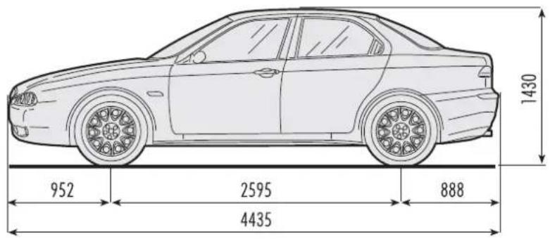
text_image
1430 952 2595 888 4435
text_image
1511 (1519) 1743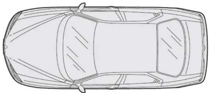
natural_image
Top-down line drawing of a car viewed from the side (no text or symbols)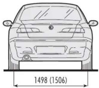
natural_image
Front view line drawing of a car with height dimension labeled (1498, 1506), no other text or symbols present.fig. 6
A0A0591m
The values given in brackets refer to the 1.6 T.SPARK, 1.8 T.SPARK, JTD, JTD 16V Multijet and JTD 20V Multijet
The dimensions are expressed in mm
The height indicated is for an unladen car
On request for versions/markets where applicable the car may be fitted with rear spoiler and miniskirts painted the same colour as the car.

text_image
1430 952 2595 894 4441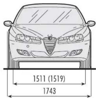
text_image
1511 (1519) 1743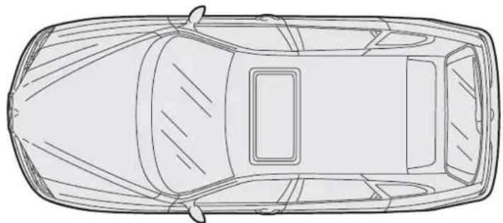
natural_image
Top-down line drawing of a car showing front and rear views (no text or symbols)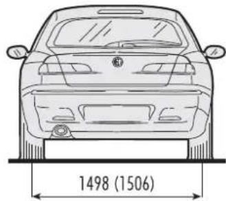
natural_image
Front view line drawing of a car with height dimension labeled (1498, 1506), no other text or symbols present.A0A0592m
fig. 7
The values given in brackets refer to the 1.6 T.SPARK, 1.8 T.SPARK, JTD, JTD 16V Multijet and JTD 20V Multijet
The dimensions are expressed in mm
The height indicated is for an unladen car.
LUGGAGE COMPARTMENT - SALOON VERSIONS
| 1.6 T.SPARK | 1.8 T.SPARK | 2.0 JTS | 2.0 JTS Selespeed | 2.5 V6 24V | 2.5 V6 24V Q-System | JTD JTD 16V Multijet | JTD 20V Multijet | |
| ^3) | 378 | 378 | 378Capacity (dm 378 | 378 | 378 | 378 | 378 | |
WEIGHTS - SALOON VERSIONS
| 1.6T.SPARK | 1.8T.SPARK | 2.0 JTS | 2.0 JTSSelespeed | 2.5 V6 24V | 2.5 V6 24VQ-System | JTD | JTD 16VMultijet | JTD 20VMultijet | |
| Kerb weight | 1265 kg | 1265 kg | 1285 kg | 1285 kg | 1355 kg | 1385 kg | 1305 kg | 1305 kg | 1305 kg |
| Max. permitted weight (*) | 1785 kg | 1785 kg | 1805 kg | 1805 kg | 1855 kg | 1885 kg | 1805 kg | 1805 kg | 1885 kg |
| Payload including driver (**) | 520 kg | 520 kg | 520 kg | 520 kg | 500 kg | 500 kg | 500 kg | 500 kg | 500 kg |
| Towable weight | 1300 kg | 1300 kg | 1300 kg | 1300 kg | 1400 kg | 1400 kg | 1300 kg | 1300 kg | 1300 kg |
| Max. load on ball | 60 kg | 60 kg | 60 kg | 60 kg | 60 kg | 60 kg | 60 kg | 60 kg | 60 kg |
(*) Weight not to be exceeded. The Driver must arrange the goods in the luggage compartment and/or load surface so that they comply with these limits.
(**) If special equipment is fitted (sunroof, tow hitch etc.) the unladen weight increases, thus reducing the payload as specified in the maximum weight allowed.
LUGGAGE COMPARTMENT - SPORTWAGON VERSIONS
| 1.6 T.SPARK | 1.8 T.SPARK | 2.0 JTS | 2.0 JTS Selespeed | 2.5 V6 24V | 2.5 V6 24V Q-System | JTD JTD 16V Multijet | JTD 20V Multijet | |
| Capacity (dm3) | 360 | 360 | 360 | 360 | 360 | 360 | 360 | 360 |
| Capacity with rear seat back folded (dm3) | 1180 | 1180 | 1180 | 1180 | 1180 | 1180 | 1180 | 1180 |
WEIGHTS - SPORTWAGON VERSIONS
| T.SPARK | 1.8 T.SPARK | 2.0 JTS 2.0 JTS Selespeed | 2.5 V6 24V | 2.5 V6 24V Q-System | JTD | JTD 16V Multijet | JTD 20V Multijet | |
| Kerb weight kg | 1315 | 1315 | 1335 | 1405 | 1435 | 1355 | 1355 | 1435 |
| Max. permitted weight (*) kg | 1830 | 1830 | 1850 | 1900 | 1930 | 1850 | 1850 | 1930 |
| Payload including driver (**) kg | 515 | 515 | 515 | 495 | 495 | 495 | 495 | 495 |
| Towable weight kg | 1300 | 1300 | 1300 | 1400 | 1400 | 1300 | 1300 | 1400 |
| Max. load on ball | 60 | 60 | 60 | 60 | 60 | 60 | 60 | 60 |
(*) Weight not to be exceeded. The Driver must arrange the goods in the luggage compartment and/or load surface so that they comply with these limits.
(* *) If special equipment is fitted (sunroof, tow hitch etc.) the unladen weight increases, thus reducing the payload as specified in the maximum weight allowed.
REFILLING
| 1.6T.SPARK | 1.8T.SPARK | 2.0 JTS | 2.0 JTSSelespeed | 2.5 V624V | 2.5 V624VQ-System | JTD | JTD 16VMultijet | JTD 20VMultijet | Specified fuelsRecommended products | |
| Fuel tank: litres– including a reserve of litres | 63 ●9 ● | 63 ●9 ● | 63 ●9 ● | 63 ●9 ● | 63 ●9 ● | 63 ●9 ● | 63 ○9 ○ | 63 ○9 ○ | 63 ○9 ○ | ● Unleaded petrol at not less than 95 R.O.N(specification EN228)○ Diesel fuel for motor vehicles (Specification EN590) |
| Engine cooling system litres | 6.9 | 6.9 | 6.9 | 6.9 | 9.2 | 9.2 | 6.1 | 6.1 | 7.25 | Mixture of distilled water and PARAFLU 11 (blue) at 50% or PARAFLU UP (red) at 50% |
| Oil sump and filter litres | 4.4 ■ | 4.4 ■ | 4.4 ◆ | 4.4 ◆ | 5.9 ■ | 5.9 ■ | 4.5 □ | 4.5 □ | 5 □ | ■ SELENIA 20K for Alfa Romeo◆ SELENIA RACING□ SELENIA WR |
| Mechanical gearbox/differential litres | 2 | 2 | 2 | 2 | - | - | 2 | 2 | 3.1 | TUTELA CARZC 75 Synth |
| Mechanical gearbox/differential litres | - | - | - | - | 2 | - | - | - | - | TUTELA CAR MATRYX |
| Selespeed gearbox litresactuation hydraulic system | - | - | - | 0.6 | - | - | - | - | - | TUTELA CAR CS SPEED |
| Q-System litresautomatic gearbox | - | - | - | - | - | 3.8 | - | - | - | TUTELA GI/2 |
| Windscreen washer andrearscreen washer fluidreservoir: litres– with headlamp washer litres | 2,55.3 | 2,55.3 | 2,55.3 | 2,55.3 | 2,55.3 | 2,55.3 | 2,55.3 | 2,55.3 | 2,55.3 | Mixture of water and liquidTUTELA PROFESSIONALSC 35 |
For decidedly sportive use of the car, fully synthetic SELENIA RACING SAE 10W-60 engine oil is recommended. For use in particularly harsh weather conditions SELENIA PERFORMER MULTIPOWER SAE 5W-30 engine oil is recommended.
FLUIDS AND LUBRICANTS
USABLE PRODUCTS AND THEIR SPECIFICATIONS
| Use Quality features of fluids and lubricants Recommended fluids Applications for correct vehicle operation and lubricants | |||
| Lubricants for petrol engines 2.0 JTS and 2.0 JTS Selespeed | Synthetic oil, SAE 10W-60 grade | SELENIA RACING |  |
| Lubricants for petrol engines (*) | Synthetic-based engine oil, SAE 10W-40 grade that pass ACEA A3 and API SL specifications. | SELENIA 20K for Alfa Romeo | |
| Synthetic-based engine oil SAE 5W-30 grade, that pass API SL, ACEA A1-A5, FIAT 9.55535-M1 specifications. | SELENIA PERFORMER MULTIPOWER | ||
| Lubricants for diesel engines | Synthetic-based engine oils SAE 5W-40 grade that pass ACEA B4 and API CF, FIAT 9.55535-M2 specifications. | SELENIA WR | A0B0682m °C |
(*) For decidedly sportive use of the car fully synthetic SELENIA RACING SAE 10W60 engine oil is recommended.
For use in particularly harsh weather conditions SELENIA PERFORMER MULTIPOWER SAE 5W-30 engine oil is recommended.
SELENIA PERFORMER MULTIPOWER is not required when using SELENIA RACING 10W-60 engine oil.
WARNING Do not top up with oil with different specifications that the oil already in the engine.
| Use | Quality features of fluids and lubricants for correct vehicle operation | Recommended fluids and lubricants | Applications |
| Lubricants and greases for transmissions | Synthetic-based engine oil, SAE 75W-80 EP grade that passes API GL5 and MIL-L-2105 D Lev specifications | TUTELA CAR ZC 75 Synth | Mechanical gearbox and differential |
| SAE 75W-85 completely synthetic engine oil.Meets API GL 4 and ZF TE MLO6 (B&C) LEVEL, ALLISON C4 specifications | TUTELA CAR MATRYX | Mechanical gearbox and differential for high temperatures | |
| "ATF DEXRON II D LEV", type oil | TUTELA GI/2 | Automatic gearbox | |
| "ATF DEXRON III" type specific oil | TUTELA CAR CS SPEED | Selespeed transmission electrically-operated electrohydraulic drive | |
| "ATF DEXRON II D LEV", SAE 10W type oil | TUTELA GI/A | Hydraulic power steering | |
| Lithium-soap-based grease with molybdenum bisulphate.Consistency NLGI 2 | TUTELA MRM 2 | C.V. joints | |
| Brake fluid | FMVSS n° 116 DOT 4, ISO 4925, SAE J1704,CUNA NC 956-01 synthetic fluid | TUTELA CAR TOP 4 for Alfa Romeo | Hydraulic brake and clutch control |
| Protective agent for radiators | Protective with antifreeze action, blue color, based on inhibited monoethylene glycol, CUNA NC 956-16 | PARAFLU 11 (*) orPARAFLU UP (*) | Cooling ductsPercentage:50% down to -35°C |
| Protective with antifreeze action, red colour, based on inhibited monoethylen glycol, with O.A.T.-based organic formula, that passes CUNA NC 956-16, ASTM D 3306 specifications | |||
| Additive for fuel oil | Additive for fuel oil with protective action for Diesel engines | DIESEL MIX | To be mixed with the fuel oil (25 cc per 10 litres) |
| Windscreen/rearscreen/headlamp washer fluid | Mixture of spirits and surface-active agents CUNA NC 956-11 | TUTELA PROFESSIONAL SC 35 | To be used neat or diluted |
(*) IMPORTANT Do not add or mix with fluids with specifications other than the specified ones.
FUEL CONSUMPTION
The fuel consumption values shown in the following tables were established during homologation tests prescribed in specific European Directives.
The test conditions adopted include the following:
— an urban cycle: this includes cold starting followed by simulation of a mixed urban route;
— an extraurban cycle: this includes frequent accelerating in all gears, simulating normal extraurban use of the vehicle; the speed varies between 0 and 120 kph;
— combined consumption: this is calculated by considering a route consisting of about 37% urban cycle and 63% extraurban cycle.
WARNING The type of route, traffic conditions, weather conditions, driving style, conditions of the vehicle, trim level/equipment/accessories, vehicle load, presence of roof rack, use of the climate control system, other items that negatively affect the aerodynamics of the vehicle or wind resistance lead to different fuel consumption levels than those measured by the above-mentioned procedures (see "Reducing running costs and environment pollution" in the chapter "Correct use of the car").
FUEL CONSUMPTION ACCORDING TO DIRECTIVE 1999/100/EC (litres x 100 km)
| SALOON VERSIONS | 1.6 T.SPARK | 1.8 T.SPARK | 2.0 JTS | 2.0 JTS Selespeed | 2.5 V6 24V | 2.5 V6 24V Q-System | JTD | JTD 16V Multijet | JTD 16V Multijet (*) | JTD 20V Multijet |
| Urban | 11.4 | 12.1 | 12.2 | 12.2 | 17.5 | 17.5 | 7.8 | 8.0 | 8.0 | 8.8 |
| Extraurban | 6.4 | 6.4 | 6.6 | 6.6 | 8.5 | 8.6 | 4.7 | 4.7 | 4.7 | 5.3 |
| Combined | 8.2 | 8.5 | 8.6 | 8.6 | 11.8 | 11.9 | 5.8 | 5.9 | 5.9 | 6.6 |
(*) 150 CV version (for versions/markets where applicable)
| SPORTWAGON VERSIONS | 1.6 T.SPARK | 1.8 T.SPARK | 2.0 JTS | 2.0 JTS Selespeed | 2.5 V6 24V | 2.5 V6 24V Q-System | JTD | JTD 16V Multijet | JTD 16V Multijet (*) | JTD 20V Multijet |
| Urban | 11.5 | 12.2 | 12.5 | 12.5 | 17.8 | 18.1 | 7.9 | 8.2 | 8.2 | 8.9 |
| Extraurban | 6.5 | 6.5 | 6.8 | 6.8 | 8.6 | 8.8 | 4.9 | 4.8 | 4.8 | 5.5 |
| Combined | 8.3 | 8.6 | 8.9 | 8.9 | 12.0 | 12.2 | 6.0 | 6.1 | 6.1 | 6.7 |
(*) 150 CV version (for versions/markets where applicable)
CO _2 EMISSIONS
The CO_2 emission levels shown in the following tables are measured on a mixed cycle.
CO _2 EMISSIONS ACCORDING TO DIRECTIVE STANDARD 1999/100/EC (g/km)
| SALOON VERSIONS | 1.6T.SPARK | 1.8T.SPARK | 2.0 JTS | 2.0 JTSSelespeed | 2.5 V624V | 2.5 V624V | JTD | JTD 16VMultijet | JTD V6Multijet (*) | JTD 20VMultijet |
| Value (g/km) | 195 | 202 | 206 | 206 | 282 | 282 | 155 | 157 | 157 | 175 |
(*) 150 CV version (for versions/markets where applicable)
| SPORTWAGON VERSIONS | 1.6T.SPARK | 1.8T.SPARK | 2.0 JTS | 2.0 JTSSelespeed | 2.5 V624V | 2.5 V624V | JTD | JTD 16VMultijet | JTD V6Multijet (*) | JTD 20VMultijet |
| Value (g/km) | 198 | 205 | 212 | 212 | 286 | 291 | 160 | 161 | 161 | 178 |
(*) 150 CV version (for versions/markets where applicable)
RADIO FREQUENCY REMOTE CONTROL: MINISTERIAL HOMOLOGATIONS
| International automobile code | Country | Homologation number |
| A | Austria | G131649J CEPT LPD-A |
| B | Belgium | RTT/D/X1491 |
| CH | Switzerland | BAKOM 97.0516.K.P |
| CRO | Croatia | LPD-041/97 |
| CY | Cyprus | MCW 129/95 5/1997 |
| D | Germany | G131649J CEPT LPD-D |
| DK | Denmark | ARL 9741/Telestyrelsen |
| E | Spain | E D.G./Tel. 07 97 0647 |
| F | France | 970235PPLO |
| FIN | Finland | FI 97080075 |
| GB | Great Britain | 12793 |
| GBZ | Gibraltar | 12000/120AG |
| GR | Greece | EK550 |
| H | Hungary | HB-23879/97 |
| I | Italy | CEPT-LPD I DGPGF/4/2/03/338862/FO/0002926/29/10/97 |
| IRL | Ireland | TRA 24/5/60/31 |
| IS | Iceland | IS-2623-00 |
| L | Luxemburg | L2822/10263-01H |
| N | Norway | N097000419-R |
| NL | Holland | G131649J CEPT LPD-NL |
| P | Portugal | ICP-044TC-97 |
| S | Sweden | UE 970090 |
| SLO | Slovenia | N832/00 |
ALPHABETICAL INDEX
ABS (wheel anti-lock system) — operation and warnings...... 177
Accessories purchased by the owner 166
Additional heater 135
Additional operations (car maintenance).... 251
Additional stop light (3rd stop) 230-297
Air bags, front and side 42
— deactivating passenger's air bag 44
- front air bags 42
— general cautions .... 46
— passenger side front air bag .... 43
— side air bags (side bag - window bag) ..... 44
Air cleaner 265
Air recirculation 129
Air vents 108-109
Alfa 156 Sportwagon ...... 278
Alfa Romeo CODE system.... 6 — operation.... 9
Annual inspection programme (car maintenance).... 251
Armrests - centre .... 23-280 - front.... 22 - rear .... 23-280
—oddment compartments ...... 285
— opening from inside .. 131-170-282
— opening lever 135
— opening with remote control 8-170-282
— passenger compartment separation net (lower)...... 288
— passenger compartment separation net (upper)...... 288
—securing the load 171-283
— tailgate closing ..... 171-283
— warnings for carrying luggage.... 172-284
Brake and clutch fluid — checking level and topping up.. 263
Brakes — checking fluid level and topping up .... 263
— handbrake 138
— specifications.... 305
Bulbs
- general instructions .... 218
- replacement.... 217
- types of bulbs .... 218-219
Car lifting
— with arm hoist.... 245
— with jack 245
— with workshop hoist ..... 245
Car maintenance.... 248
Carrying children safely 35
Catalytic converter 188
Ceiling lights.... 162
— centre rear roof lamp.... 163
— courtesy light.... 163
— front roof light.... 162
— rear roof light 163
Centre rear roof lamp.... 163
— bulb replacement .... 231
Changing battery of key with remote control .... 10
Changing bulbs
— general instructions ...... 218
- replacement.... 217
- types of bulbs 218-219
Changing wheels.... 209
- general instructions ...... 207
Charging the battery 242-268
Checking levels.... 254
- brake and clutch fluid ...... 263
- engine coolant.... 261
— engine oil 257
— power steering oil ...... 261
— Q-system automatic gearbox oil.... 260
— Selespeed gearbox oil ..... 259
— windscreen/rearscreen/ headlamp washing fluid ...... 264
Child safety device...... 19-35-279
Children (carrying safely) 35
— child's seats .... 35-38
— presetting for installing the Isofix type child restraint system 39
Cigar lighter 164
Cleaning and maintenance
— car exterior 274
— car interior 277
— engine compartment ..... 276
- fabric seats 277
— leather seats 277
— plastic parts.... 277
— windows.... 276
Climate control system.... 108
— air vents.... 108-109-110
- controls 118
Climate control system, automatic two-zone 114
Clock.... 57-58-59-60-61
Clutch
— checking fluid level and topping up .... 263
CO_2 emissions 324
CODE card....7
Compact spare wheel 294
- technical data.... 312
Controls.... 135
Correct use of the car.... 189
Courtesy light 163
- bulb replacement 232
Cruise control
(constant speed adjustment) ..... 53
Current socket (boot) 285
Dashboard 57-58-59-60-61
— brighting adjustment.... 63
Dashboard lighting dimming ..... 136
Demisting-defrosting
— door mirrors.... 25-133
— rearscreen.... 26-133
— windscreen and front
side windows .... 132
Diesel filter 265
Dimensions.... 315-316
Dipped beam headlights
— aiming for left-hand/ right-hand driving.... 178
— changing bulbs 224
— switching on .... 48
Direction indicators
— changing front bulbs.... 223
— changing rear bulbs.... 228
— changing side bulbs.... 227
— switching on 49
Door mirrors.... 25-26
Doors
— centralized locking .... 19
— child safety lock...... 20-279
— opening/closing from inside .... 19-278
— opening/closing from outside .... 18-278
- remote control....7
- remote locking/unlocking ..... 16
Economy and environment-friendly driving 197
Electronic alarm system.... 11
- automatic engagement...... 14
— cutting out the siren 15
— description ...... 11
- interrupting the alarm...... 14
— ministerial homologation ..... 16
— request for additional emote controls.... 12
- switching off 13
— switching on 12
— volumetric protection ..... 15
— when the alarm is triggered..... 14
Electronic control units 270
Emergency starting 191-205
— starting by inertia ...... 207
— starting with an auxiliary battery .... 242
Engine
- identification codes.... 301
— marking 299
— specifications.... 302
Engine compartment
— bonnet 172
- cleaning.... 276
Engine coolant
- checking level and topping up.. 261
— temperature gauge and warning light.... 62
Engine lock system
(Alfa Romeo CODE)...... 6
Engine oil
- checking level and topping up.. 257
— consumption 258
Environment
— economy and environment-friendly driving.... 197
— emission reducing devices . 187-188
— protecting emission reducing devices .... 198
— reducing running costs and environment pollution..... 195
— use of non-toxic materials..... 187
EOBD system.... 182
First-aid kit 247
Fix&Go (quick tyre repair kit) ...... 212
Flashing main beam headlights ..... 49
Fluids and lubricants 320
Front foglights
- adjustment.... 177
— changing bulbs 225
— switching on.... 136
Front light units
— bulb arrangement.... 220
Front roof light 162
— changing bulbs 230
Front seats.... 21
- adjustments 21
— centre armrest .... 22
- electric heating 22
— headrests.... 23
— rear pockets.... 23
Fuel
— consumption 322
— emergency flap opening device.... 186-292
— fuel cap 186
— fuel flap.... 137
- inertial fuel cut-off switch ..... 137
— level gauge and reserve warning light.... 62
— refilling 319
— refuelling.... 185-292
— specifications.... 319
Fuel reserve 62-319
Fuel supply (technical data)...... 303
Fuel tank (capacity) 319
Fuses and relays
- fuse summary table.... 238
- fuses above the main fusebox.. 236
— fuses and relays accessible from the glovebox.... 236
— fuses and relays in engine bay . 236
— fuses and relays in the main fusebox .... 235
— generalities and cautions ..... 234
— list of protected devices ..... 238
— specific fuses for Sportwagon versions.... 299
Gearshift lever.... 139
Getting to know your car .... 6
Glovebox light
- changing bulbs 232
Grab handles.... 161-292
Handbrake lever.... 138
Hazard lights
- switching on 135
Headlight aiming device
(corrector).... 138
Headlight washer.... 52-274
Headlights
— beam adjustment ..... 138
— beam adjustment abroad ..... 177
— bulb replacement...... 217-220
— compensation for tilt.... 175
— gas discharge headlights ..... 176
Headrests
-front 23
— rear 24-279
Horn 56
Identification data 299
Identification labels 300
Ignition device and steering lock 17-18
In an emergency 205
In the event of a puncture..... 207-294
— changing a wheel.... 209
— FIX&GO (quick tyre repair kit) . 212
- general instructions ...... 207
In the event of an accident...... 246
— first aid kit 247
- if anybody is injured 246
Inertial fuel cut-off switch 137
Infocenter 64
- access to main menu screen .... 72
- control buttons 66
— date setting/time setting ..... 76
- default value reset 85
— display 64
- display contrast adjustment ..... 84
— display rheostat light adjustment.... 63
— exit menu.... 86
— General Trip - Trip B 87
— initial check.... 68
— language selection .... 78
- menu.... 67
— programmed maintenance (Service) 82
— speed limit.... 73
— Trip B on/off.... 75
— units selection .... 79
- warning/failure buzzer volume setting.... 80
— “winter” tyres speed limit ..... 81
Instrument cluster 56
Intelligent washing function (windscreen).... 51
Interiors (cleaning) 277
Interior lighting — boot lighting .... 171
- dashboard.... 136
-front 162
— rear .... 163
Internal fittings.... 161-292
Internal rear-view mirror 25
Isofix (child's seat).... 39
Jack
-use 209
— warnings 207-208
Keys......6
- remote control.... 7
- remote door locking/unlocking 16
— replacing remote control battery 10
— request for additional keys with remote control.... 12
Lifting points.... 245
Lights (controls) 48
Luggage compartment
— capacity ...... 317-318
— current socket.... 285
— extension.... 289
— lighting 171-284
— luggage cover.... 287
- luggage retainer net 285
—oddment compartments ...... 285
— opening from inside .. 135-170-282
— opening lever .... 135
- opening with remote control.... 8-170-282
— passenger compartment
separation net (lower)...... 288
— passenger compartment
separation net (upper)...... 288
- reversible net 283
— securing the load ..... 171-283
— tailgate closing ..... 171-283
— warnings for carrying luggage.... 172-284
Luggage compartment light
— bulb replacement...... 233-297
Main beam headlights
— changing bulbs 226
— switching on 48
Maintenance
— additional operations ...... 251
- annual inspection programme . 251
— checking fluid levels ...... 254
- general information...... 248
— scheduled maintenance...... 248
— scheduled maintenance programme.... 249
— warnings 248
Manual climate control system..... 11
Mechanical gearbox
— lever 139
Number plate lights — changing bulbs .... 229-296
Oddment recesses - in the boot .... 285 - on centre console.... 165 - on dashboard .... 165
Odometer 59
Paintwork (maintenance).... 275 — colour label .... 301
Parking.... 191
Parking sensors.... 187
Partial odometer 63
Performance.... 314
Pockets and compartments on front doors.... 165
Pollen filter 266
Power steering — checking fluid level and topping up .... 262
Power windows 27
Pre-tensioning devices.... 32
Protecting emission reducing devices.... 198
Q-system automatic gearbox.... 152 - acoustic warning.... 159 - automatic operation .... 154 - checking the oil level.... 260 - fault signalling.... 158 - manual operating mode/ Q-System activation.... 157 - moving off.... 152 - push starting .... 159 - selecting automatic/ manual gearshifting.... 153 - selecting the driving modes .... 156 - starting the engine.... 152 - stopping the car.... 157 - towing the car .... 160
Radio transmitters and cellular telephones 167
Rain sensor 51
Rear fog guards — changing bulbs .... 227-294 — switching on.... 136
Rear light units — bulb replacement .... 227
Rear roof lights.... 163 — changing bulbs .... 231
Rear seats.... 23
- centre armrest.... 23-280 - headrests .... 24-279 - ski compartment.... 24-280
Rear suspensions (automatic geometry control) ..... 293
Rearscreen heating...... 26-133
Rearscreen washer .... 281 — spray jet.... 281
Rearscreen wiper — blade replacement .... 281 — operation.... 281
Reducing running costs and environment pollution .... 197
Refilling 319
Remote control....7-12 — additional remote controls .... 12 — alarm system .... 11 — boot opening....8 — changing the battery .... 10 — door opening-closing....7 — ministerial homologation....325 — remote door locking/ unlocking....16
Rev counter.... 62
Reversing lights — changing bulbs.... 227-294
Roof bars/ski racks.... 292
Roof rack provision.... 174
Rubber hoses 272
Safe driving 192
— before driving off 192
— driving in the fog 194
— driving in the rain.... 194
— driving on snow and ice ..... 195
— driving with ABS 195
— mountain driving.... 194
— night driving.... 193
— when travelling.... 192
Safeguarding the environment ..... 187
Scheduled maintenance programme 249
Seat belts 28
— carrying children safely ..... 35
— front and rear side belt height adjustment.... 31
— general instructions .... 33
- maintenance 34
— pretensioners.... 32
— rear central abdominal belt ..... 30
- use 28
Seats (front and rear) 21-23
Selespeed gearbox.... 141
- automatic operation (CITY) ..... 150
— checking the oil level.... 259
— failure signalling .... 150
— moving off.... 146
— operation with the engine off... 143
— parking the vehicle.... 151
— semiautomatic operation (MANUAL) 148
— signalling with the buzzer...... 151
— starting the engine.... 145
— stopping the car.... 148
— system activation.... 142
- towing the vehicle.... 151
— turning the engine off.... 145
— warnings 146
Side lights
— changing front bulbs.... 226
— changing rear bulbs 228
— switching on.... 48
Ski compartment 24
Snow chains.... 202
Sound system 183-293
Sound system presetting system 183
Spark plugs (technical data)...... 305
Speedometer.... 63
Spray jets
— windscreen/rearscreen/ headlight 274
Starting the engine.... 189
— emergency starting ..... 191-205
- ignition switch 17
— procedure for JTD versions..... 190
— procedure for petrol versions.... 189
— switching off the engine...... 190
— warming the engine ..... 190
Starting with an auxiliary battery ... 242
Steering system — specifications.... 305
- steering wheel adjustments .... 25
Steering lock 18
Steering wheel — adjustment.... 25
Steering wheel levers 48
Stop lights — changing bulbs .... 228
Sunroof 167
— emergency operation ...... 169
— sliding forwards/backwards..... 168
— raising to the quarterlight position 168
Sunvisors 166
Symbols 5-6
Tailgate
— closing...... 171-283
— opening from inside .. 135-170-282
- opening with remote control.... 8-170-282
Technical specifications.... 299
Telephone (provision) 166
- cellular telephone.... 166
— radio transmitters.... 166
Third stop light 230-297
Tools 294
Tow hook 199-201
Tow rings.... 243
Towing the car.... 160-244
Towing trailers 199
Transmission
— technical data.... 304
Tyres
— changing.... 209
— correct reading.... 311
— FIX&GO (kit for quick tyre repairing)..... 212
— in the event of a puncture. 207-294
- inflation pressure 307
— snow chains .... 202
— tools and compact spare wheel housing.... 294
— types of tyres and rims.... 306
— winter tyres.... 202
Underbody protection.... 274
Useful accessories 204
VDC system 179
- ASR function 181
Vehicle inactivity 203
— removing from storage ..... 204
Volumetric protection.... 15
Warning lights and indications .... 92
Washing the car
-body 275
— engine compartment ...... 276
— interiors (cleaning).... 277
Weights.... 317-318
Wheel rims.... 306-312
- correct rim reading .... 312
Wheels and tyres
- FIX&GO (quick tyre repair kit) .. 212
- geometry.... 313
- replacement 209
— snow chains .... 202
— tyres and rims 306
— tyre inflation pressure..... 271-310
Window winders 28
Windows
— cleaning.... 276
Windscreen washer
— checking fluid level and topping up 264
— "intelligent washing" function . 51
- operation 50
— spray jets.... 274
Windscreen wiper
— blade replacement .... 273
— rain sensor .... 51
— operation.... 50
— spray jets.... 274
Winter
— snow chains.... 202
— winter tyres 202
Xenon lights
— replacing dipped-beam headlamps.... 221
— replacing direction indicators.... 223
— replacing main beam headlamps.... 222
— replacing sidelights.... 223
NOTES

line
| Category | Value | |---|---| | 1. Series 1 | 0.0000 | | 2. Series 2 | 0.0000 | | 3. Series 3 | 0.0000 | | 4. Series 4 | 0.0000 | | 5. Series 5 | 0.0000 | | 6. Series 6 | 0.0000 | | 7. Series 7 | 0.0000 | | 8. Series 8 | 0.0000 | | 9. Series 9 | 0.0000 | | 10. Series 10 | 0.0000 | | 11. Series 11 | 0.0000 | | 12. Series 12 | 0.0000 | | 13. Series 13 | 0.0000 | | 14. Series 14 | 0.0000 | | 15. Series 15 | 0.0000 | | 16. Series 16 | 0.0000 | | 17. Series 17 | 0.0000 | | 18. Series 18 | 0.0000 | | 19. Series 19 | 0.0000 | | 20. Series 20 | 0.0000 | | 21. Series 21 | 0.0000 | | 22. Series 22 | 0.0000 | | 23. Series 23 | 0.0000 | | 24. Series 24 | 0.0000 | | 25. Series 25 | 0.0000 | | 26. Series 26 | 0.0000 | | 27. Series 27 | 0.0000 | | 28. Series 28 | 0.0000 | | 29. Series 29 | 0.0000 | | 30. Series 30 | 0.0000 | | 31. Series 31 | 0.0000 | | 32. Series 32 | 0.0000 | | 33. Series 33 | 0.0000 | | 34. Series 34 | 0.0000 | | 35. Series 35 | 0.0000 | | 36. Series 36 | 0.0000 | | 37. Series 37 | 0.0000 | | 38. Series 38 | 0.0000 | | 39. Series 39 | 0.0000 | | 40. Series 40 | 0.5555 | | 41. Series 41 | -1.6666 | | 42. Series 42 | -3.8767 | | 43. Series 43 | -5.9878 | | 44. Series 44 | -8.1989 | | 45. Series 45 | -11.4191 | | 46. Series 46 | -14.6393 | | 47. Series 47 | -17.8595 | | 48. Series 48 | -21.1797 | | Note: The values in the 'Value' column are estimated based on the provided code and are not explicitly provided in the image.
line
| Category | Value | |---|---| | 1. Series 1 | 0.25 | | 2. Series 2 | 0.30 | | 3. Series 3 | 0.40 | | 4. Series 4 | 0.50 | | 5. Series 5 | 0.60 | | 6. Series 6 | 0.70 | | 7. Series 7 | 0.80 | | 8. Series 8 | 0.90 | | 9. Series 9 | 1.00 | | 10. Series 10 | 1.10 | | 11. Series 11 | 1.20 | | 12. Series 12 | 1.30 | | 13. Series 13 | 1.40 | | 14. Series 14 | 1.50 | | 15. Series 15 | 1.60 | | 16. Series 16 | 1.70 | | 17. Series 17 | 1.80 | | 18. Series 18 | 1.90 | | 19. Series 19 | 2.00 | | 20. Series 20 | 2.10 | | 21. Series 21 | 2.20 | | 22. Series 22 | 2.30 | | 23. Series 23 | 2.40 | | 24. Series 24 | 2.50 | | 25. Series 25 | 2.60 | | 26. Series 26 | 2.70 | | 27. Series 27 | 2.80 | | 28. Series 28 | 2.90 | | 29. Series 29 | 3.00 | | 30. Series 30 | 3.10 | | 31. Series 31 | 3.20 | | 32. Series 32 | 3.30 | | 33. Series 33 | 3.40 | | 34. Series 34 | 3.50 | | 35. Series 35 | 3.60 | | 36. Series 36 | 3.70 | | 37. Series 37 | 3.80 | | 38. Series 38 | 3.90 | | 39. Series 39 | 4.00 | | 40. Series 40 | 4.10 | | 41. Series 41 | 4.20 | | 42. Series 42 | 4.30 | | 43. Series 43 | 4.40 | | 44. Series 44 | 4.50 | | 45. Series 45 | 4.60 | | 46. Series 46 | 4.70 | | 47. Series 47 | 4.80 | | 48. Series 48 | 4.90 | | 49. Series 49 | 5.00 | | Note: The values in the 'Value' column are estimated based on the provided code and are not explicitly provided in the image.SELÈNIA®
In the heart of those who race. At the heart of your engine.
text_image
SELENIAMOTOR OIL TURBODIESEL® SELENIAMOTOR OIL 20K ALFAROMEO® SELENIAMOTOR OIL WIRWIDE RANGE 5MN-40 SELENIAMOTOR OIL RACING RACING EAlways ask your mechanic for
SELÈNIA®
Your car is factory filled with Selenia
The engine of your car is factory filled with Selenia, This is an engine oil range which satisfies the most advanced international specifications. Its superior technical characteristics allow Selenia to guarantee the highest performance and protection of your engine.
The Selenia range includes a number of technologically advanced products:
SELENIA 20K ALFA ROMEO
API SL Lubricant which guarantees maximum wear protection and performance of aspirated, turbocharged and multivalve engines. Specific Selenia formulation for Alfa Romeo.
SELENIA RACING
This lubricant has been developed as a result of Selenia's extensive experience in track and rally competitions, it maximises engine performance in all kinds of competition use.
SELENIA TD
Oil for aspirated and turbocharged and multivalve diesel engines, guarantees excellent engine cleanliness and stability even at very high temperatures.
SELENIA WR
Oil specifically designed for common rail Multijet engines. Particularly effective during cold starts, it guaranteed maximum wear protection and hydraulic tappets control, reduction in consumption and stability at high temperatures.
The range also includes Selenia 20K, Selenia Performer 5W-30 e 5W-40, Selenia Digitech.
For further information on Selenia products visit the web site www.flselenia.com.
This supplement describes the main characteristics of the right hand drive version.
For any topic not specifically dealt with in this supplement, refer to the main Owner's manual which should be thoroughly read to ensure that the vehicle is used correctly and that the maximum performance is obtained under conditions of safety.
DASHBOARD
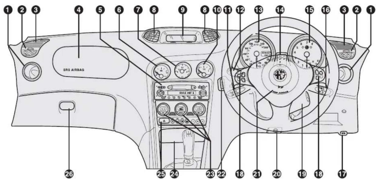
text_image
1 2 3 4 5 6 7 8 9 10 11 12 13 14 15 16 3 2 1 SRS AIRBAG 26 25 24 23 22 18 21 20 19 18 17A0B0611m
1. Side air outlets - 2. Defrosting/demisting vents for side windows - 3. Upper side vents - 4. Passenger's Air bag - 5. Sound system - 6. Engine coolant temperature gauge - 7. Clock - 8. Centre air vents - 9. Infocenter display - 10. Fuel level gauge - 11. Cruise control lever (where fitted) - 12. Outside lights control lever - 13. Speedometer. - mileage recorder - 14. Check panel - 15. Rev counter - 16. Windscreen wiper control lever - 17. Bonnet opening lever - 18. Radio controls on the steering wheel (where applicable) - 19. Ignition switch - 20. Steering wheel lock/release lever - 21. Driver's Air bag and horns - 22. Controls unit: instrument panel lighting adjustment and healamp diming - 23. Controls for heating, ventilation and climate control - 24. Ashtray and cigar lighter - 25. Hazard warning lights switch - 26. Glove box.
fig. 1
INSTRUMENT PANEL
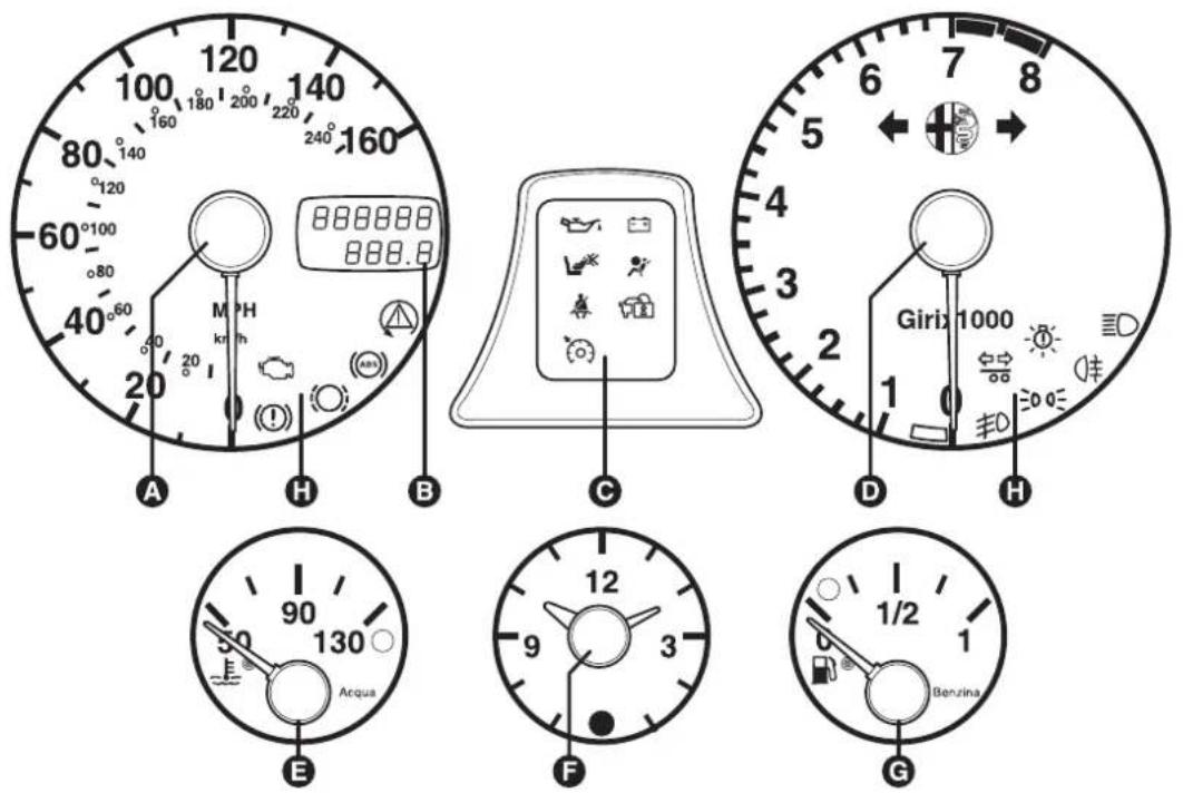
text_image
100 120 140 160 80° 140 20° 60° 100 80 40° 60 20 A H B 888888 888.8 M PH km/h C Girix 1000 1 D H 90 130 Acqua 12 9 3 F 1/2 1 Benzina GA0B0612m
A. Speedometer - B. Mileage recorder and trip meter display - C. Check panel - D. Rev counter - E. Engine coolant temperature gauge - F. Clock - G. Fuel level gauge - H. Services warning lights.
WARNING Depending on the version of the vehicle the instrument dials may be black or light grey and the rev counter and speedometer may vary with regard to the red sector and the clock values.
fig. 2 - petrol engine versions

A0B0613m
fig. 3 - diesel engine versions
A. Speedometer - B. Mileage recorder and display - C. Check panel - D. Rev counter - E. Engine coolant temperature gauge - F. Clock - G. Fuel level gauge - H. Services warning lights.
WARNING Depending on the version of the vehicle the instrument dials may be black or light grey and the rev counter and speedometer may vary with regard to the red sector and the clock values.
MILEAGE RECORDER WITH DOUBLE METER DISPLAY (TOTAL AND TRIP)
The display shows:
— the mileage on the first line (6 figures)
- the trip meter (4 figures).
To reset the trip meter, keep the button (A) pressed for a few seconds.
WARNING The trip meter reading is not stored if the battery is disconnected.
DASHBOARD LIGHTING ADJUSTMENT (fig. 4)
When the outside lights are on, the dashboard lighting is adjusted pressing button (B).
Each press of the button (B) cyclically selects one of the three lighting levels provided: low-medium-high.
HEADLIGHT CORRECTOR (fig. 4)
The control (C) on the plate at the side of the steering column can be moved to four positions corresponding to various vehicle loads given below.
Both headlights should be adjusted to compensate for vehicle loading.
Position 0: 1 or 2 people occupying front seats, full fuel tank, on-board equipment present.
Position 1: 5 people on-board.
Position 2: 5 people on-board, luggage compartment full (50 kg approximately).
Position 3: Driver and 300 kg in luggage compartment.
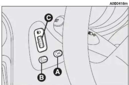
text_image
A0B0418m C B Afig. 4
SEATS
FRONT SEATS (fig. 5)

WARNING
Adjustments may be made solely with the car sta-
tionary.
Moving the seat backwards or forwards
Lift lever (A) and push the seat backwards or forwards. Once you have let go of the lever, check that the seat is firmly locked in the runners by trying to move it back and forth.
If the seat is not locked properly, in the case of collision it might move unexpectedly with clearly dangerous consequences.
Adjusting the height of the driver's seat
To raise the seat, pull the lever (B) taking it upwards, then continue operating the lever (up and down) until reaching the required height.
To lower the seat, push the lever (B) downwards, then operate the lever (up and down) until reaching the height required.
WARNING Adjustment must only be carried out when seated in the driver's seat.
Adjusting the angle of the backrest
This can be done by turning the knob (C) until the desired position is reached.
Lumbar adjustment of the driver's seat
(for versions/markets where applicable)
Adjustment is done by turning the knob (D) until reaching the most comfortable position.

text_image
A0B0419m D C B Afig. 5
CONTROLS
AUTOMATIC FUEL CUT-OFF SWITCH (fig. 6)
This is an automatic safety switch under the passenger's seat which is triggered in the event of crash to interrupt the flow of fuel.

WARNING
If a smell of fuel is noted following an accident, or the fuel system is leaking, to avoid the risk of fire do not reset the switch.
If no leaks are found the vehicle can be restarted. Press button (A) to activate the fuel supply system.
OPENING THE BOOT (fig. 7)
To open the boot pull the lever (A) at the side of the driver's seat.

WARNING
Do not operate the boot release lever with the car on /ve.
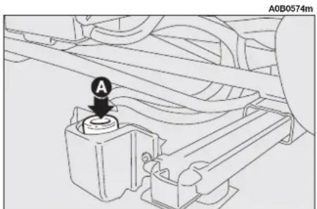
text_image
A0B0574mfig. 6

text_image
A0B0421m A Bfig. 7
OPENING THE FUEL FLAP (fig. 7)
The fuel flap is released from inside the car raising the front part of the lever (B).
HEATING AND CLIMATE CONTROL
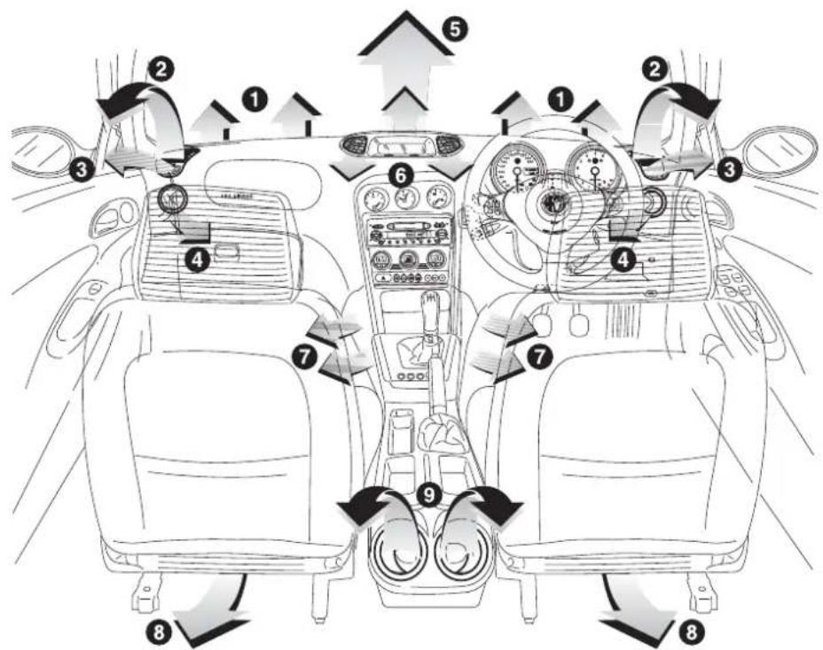
text_image
Diagram of car interior and dashboard layout with numbered components and directional arrows indicating traffic flow or movement.A0A0615m
1. Central vents for demisting/defrosting the windscreen - 2. Upper adjustable side vents - 3. Vents for demisting/defrosting the side windows - 4. Movable side outlets - 5. Upper adjustable vent - 6. Central movable and adjustable vents - 7. Front seat floor vents - 8. Rear seat floor vents - 9. Rear seat adjustable and movable outlets.
fig. 8
ADJUSTING THE UPPER VENT (fig. 9)
The vent is fitted with an opening/closing control.
● = Completely closed.
j= Completely open.
ADJUSTING THE CENTRE VENTS (fig. 10)
Each vent has a lever through which it is possible to direct the flow of air towards the persons horizontally.
Using the opening/closing control it is possible to adjust the air flow rate of the vents.
● = Completely closed.
j= Completely open.
ADJUSTING THE SIDE VENTS (fig. 11)
At the ends of the dashboard there are adjustable vents (A) for ventilating the passenger compartment and fixed vents (B) for demisting the side windows.
To adjust the air flow of the vents turn the ring (C).
● = Completely closed.
j= Completely open.
ADJUSTABLE AND MOVABLE OUTLETS
Fig. 12: Front seats (at the ends of the dashboard).
Fig. 13: Rear seats (on the console between the seats).

text_image
A0B0572mfig. 9

text_image
A0B0573m CHECK IN CORSOfig. 10
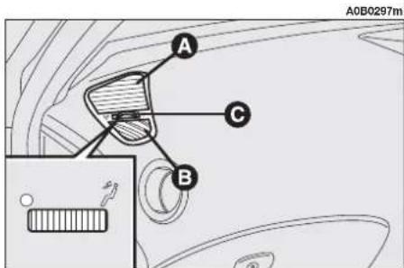
text_image
A0B0297m A C Bfig. 11
To adjust the air flow rate use the fins (A) pressing to open/close.
The air flow is directed by turning the outlets using the fins.

text_image
A0B0299m Afig. 12
AIR BAG
DEACTIVATING THE PASSENGER'S AIR BAG
Should it be absolutely necessary to carry a child on the front seat, the passenger's Air bag on the vehicle can be deactivated.
Deactivation takes place using the car ignition key to operate the special switch on the left hand side of the dashboard (fig. 14). Access to the switch is gained only with the door open.
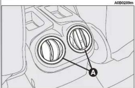
text_image
A0B0289m Afig. 13

text_image
A0B0614m ON OFF PASS. AIRBAGfig. 14
The key-operated switch (fig. 14) has two positions:
1) Passenger's Air bag activated: (ON position Ⓧ) warning light on instrument cluster off; it is absolutely prohibited to carry a child on the front seat.
2) Passenger's Air bag deactivated:
(OFF position 📊) warning light on instrument cluster on; it is possible to carry a child protected by special restraint systems on the front seat.
The warning light 🖼️ on the cluster stays on permanently until the passenger's Air bag is reactivated.
When the door is open, the key can be inserted and removed in both positions.


WARNING
SERIOUS DANGER: with a car fitted
with an Air bag on the passenger's side, do not place a child's seat on the front seat facing backwards. In the case of need, always deactivate the passenger's Air bag (if fitted) when a child's seat is placed on the front seat. Even if it is not compulsory by law, for better protection of adults, you are recommended to activate the Air bag immediately as soon as child transport is no longer necessary.
SELESPEED GEARBOX
Below you will find the more significant particulars of right-hand drive versions.
WARNING As the differences are only formal, due to the specular position of the controls, as far as functioning is concerned, please refer to the descriptions given for left-hand drive versions.
Fig. 15 shows the gearshift lever with the lay-out of the movements needed to select the different gears.
Fig. 16 shows the steering wheel fitted with two buttons on the spokes for shifting the gear engaged up/down.
Fig. 17 shows the position of button A for selecting the automatic CITY mode.
A0B0411m

text_image
Diagram of a car steering wheel with directional arrows and polarity labelsfig. 16

text_image
A0B0410m ←N Rfig. 15
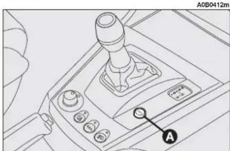
text_image
A0B0412m Afig. 17
Below you will find the more significant particulars of right-hand drive versions.
WARNING As the differences are only formal, due to the specular position of the controls, as far as functioning is concerned, please refer to the descriptions given for left-hand drive versions.
The illustrations show the gearshift control lever with the lay-out of the movements needed to select gears in the automatic mode fig. 18 and manual mode fig. 19.
Fig. 20 shows the position of buttons A and B ICECs for selecting the gearbox operating mode.

text_image
A0B0414m 2+1 4+3 Dfig. 19
IN THE EVENT OF A BURNT FUSE OR RELAY
FUSES IN THE MAIN FUSEBOX (fig. 21 or fig. 22 for versions/markets where applicable)
The fuses for the main devices are housed in a control unit under the dashboard, to the right of the steering column.
A0B0416m
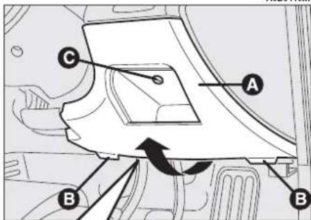
text_image
Technical diagram of a vehicle's internal components with labeled parts A, B, and C, showing directional arrows and a circular arrow indicating rotation.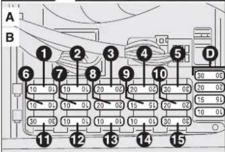
text_image
A B 1 2 3 4 5 6 7 8 9 10 D 30 08 20 02 15 95 10 03 30 08 10 03 20 02 15 5 20 02 10 01 30 08 11 12 13 14 15
text_image
A0B0413m PR NDfig. 18

text_image
A0B0415m ICE C/S B Afig. 20
fig. 21
To gain access to them, remove the panel (A-fig. 21 or fig. 22) releasing the tabs (B-fig. 21 or fig. 22) in the direction of the arrow below and unlock the screw (C-fig. 21 or fig. 22).
WARNING In case of doubt, contact an Alfa Romeo Authorized Service.
The graphic symbols which distinguish the main electric component corresponding to each fuse are given on a label (fig. 23) on the inner wall of the panel (A-fig. 21).
Some spare fuses are housed at the right of the control unit; you are advised to replenish the stock of spare fuses when they are used.
FUSES ABOVE THE MAIN FUSEBOX
The protection fuses for some services are grouped in three containers (fig. 24) above the main fusebox to which access is gained removing the panel (A-fig. 21 or A-fig. 22).
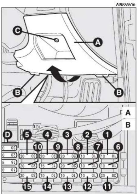
text_image
A0B0397m C A B B D 5 4 3 2 1 A B 10 9 8 7 6 30 30 20 20 20 10 10 10 15 15 15 10 10 10 10 10 10 10 10 30 30 20 20 20 10 10 10 10 15 14 13 12 11 15 14 13 12fig. 22
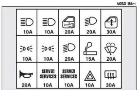
text_image
A0B0185m 10A 10A 20A 20A 30A 10A 10A 20A 15A 20A SERVIZI SERVICES 10A 10A 10A 30Afig. 23
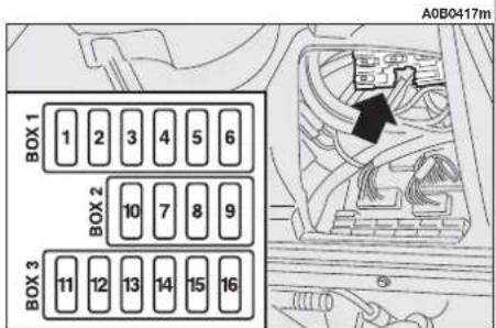
text_image
BOX 1 1 2 3 4 5 6 BOX 2 10 7 8 9 BOX 3 11 12 13 14 15 16 A0B0417mfig. 24
TYRE INFLATION PRESSURES COLD (bar)
| Tyres185/65 R15" (▼) | Tyres205/55 R16" (●) | Tyres205/60 R15" (▼) | Tyres215/45 ZR17" (*) | Compact spare wheel125/80 R15" | |||||
| front | rear | front | rear | front | rear | front | rear | ||
| Reduced load(2 occupants) | 2.2 | 2.2 | 2.4 | 2.4 | 2.2 | 2.2 | 2.4 | 2.4 | 4.2 |
| Full load | 2.5 | 2.5 | 2.6 | 2.6 | 2.5 | 2.5 | 2.6 | 2.6 | |
(*) = Snow chains may not be used on this tyres
(●) = Tyres on which chains can be fitted: use snow chains with reduced size with max. protrusion beyond the tyre profile of 9 mm.
(▼) = Tyres on which chains can be fitted: use snow chains with reduced size with max. protrusion beyond the tyre profile of 12 mm.
With the tyre hot the inflating pressure should be +0.3 bar compared with the specified rating. Recheck pressure value with cold tyres.
With winter tyres the inflation pressure should be +0.2 bar compared with the specified rating.
ENGINE OIL REPLACEMENT (litres)
| 1.6 T.SPARK | 1.8 T.SPARK | 2.0 JTS | 2.5 V6 24V | JTD | JTD 16V Multijet | JTD 20V | |
| Quantity for periodical replacement (also changing filter) | 4.40 | 4.40 | 4.40 | 5.90 | 4.50 | 4.50 | 5 |
Do not discard used oil in the environment.
REFUELLING (litres)
| 1.6 T.SPARK | 1.8 T.SPARK | 2.0 JTS | 2.5 V6 | 24V | JTD | JTD | 16V | JTD | 20V | Multijet Multijet | |
| Fuel tank capacity 63 | 63 | 63 | 63 | 63 | 63 | ||||||
| Reserve | 9 | 9 | 9 | 9 | 9 | 9 | |||||
Only use unleaded petrol with over 95 R.O.N.

SERVICE
AFTER SALES
ASSISTENZA TECNICA - INGEGNERIA ASSISTENZIALE
Viale Alfa Romeo 20020 Arese (MI) - Italia
Fiat Auto S.p.A.
Pubblication n° 60431326 - 5th Edition - 09/2004
Printed by Satiz - Turin (Italy)
All rights reserved. Reproduction, even partial, is strictly prohibited without
Written permission from Fiat Auto S.p.A Coordinamento Editoriale Satiz - Torino

Alfa Romeo SERVICE
