PowerScan PM8500 - Barcode Reader DATALOGIC - Free user manual and instructions
Find the device manual for free PowerScan PM8500 DATALOGIC in PDF.

User questions about PowerScan PM8500 DATALOGIC
0 question about this device. Answer the ones you know or ask your own.
Ask a new question about this device
Download the instructions for your Barcode Reader in PDF format for free! Find your manual PowerScan PM8500 - DATALOGIC and take your electronic device back in hand. On this page are published all the documents necessary for the use of your device. PowerScan PM8500 by DATALOGIC.
USER MANUAL PowerScan PM8500 DATALOGIC
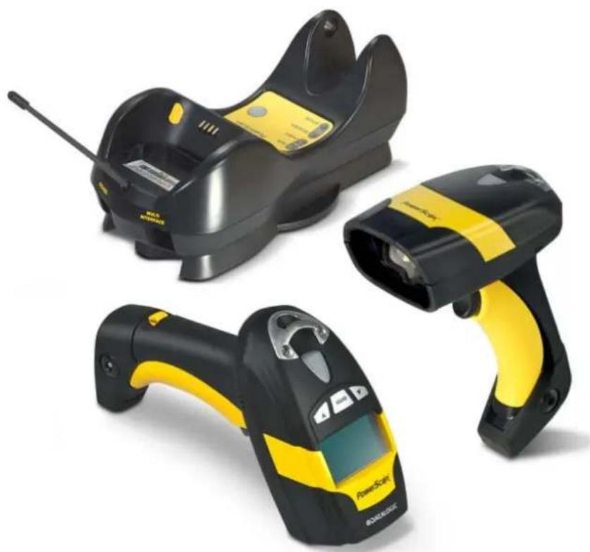
Industrial Handheld Area Imager Bar Code Reader with Datalogic's STAR Cordless System™
natural_image
Three black and yellow barcode scanner devices with visible brand logos (no text or symbols on the devices themselves)Product Reference Guide
Datalogic Scanning, Inc.
959 Terry Street
Eugene, Oregon 97402
USA
Telephone: (541) 683-5700
Fax: (541) 345-7140
An Unpublished Work - All rights reserved. No part of the contents of this documentation or the procedures described therein may be reproduced or transmitted in any form or by any means without prior written permission of Datalogic Scanning, Inc. or its subsidiaries or affiliates ("Datalogic" or "Datalogic Scanning"). Owners of Datalogic products are hereby granted a non-exclusive, revocable license to reproduce and transmit this documentation for the purchaser's own internal business purposes. Purchaser shall not remove or alter any proprietary notices, including copyright notices, contained in this documentation and shall ensure that all notices appear on any reproductions of the documentation.
Should future revisions of this manual be published, you can acquire printed versions by contacting your Datalogic representative. Electronic versions may either be downloadable from the Datalogic website (www.scanning.datalogic.com) or provided on appropriate media. If you visit our website and would like to make comments or suggestions about this or other Datalogic publications, please let us know via the "Contact Datalogic" page.
Disclaimer
Datalogic has taken reasonable measures to provide information in this manual that is complete and accurate, however, Datalogic reserves the right to change any specification at any time without prior notice.
Datalogic and the Datalogic logo are registered trademarks of Datalogic S.p.A. in many countries, including the U.S.A and the E.U. All other brand and product names referred to herein may be trademarks of their respective owners.
Microsoft Windows ^® , Windows ^® 2000, Windows ^® CE, Windows ^® NT, Windows ^® XP and the Windows logo are registered trademarks of Microsoft Corporation.
Patents
This product is covered by one or more of the following patents:
Design Pat. AU 310201; AU 310202; CN 693980; CN 735959; HK 0602013.5M001; HK 0602013.5M002; JP 1305693; KR 30-0460940; US D570,843 S.
US Pat. 6,478,226 B2; 6,512,218 B1; 6,808,114 B1; 6,877,664 B1; 6,997,385 B2; 7,053,954 B1; 7,102,116 B2; 7,282,688 B2; 7,387,246.
European Pat. 996,284 B1; 999,514 B1; 1,128,315 B1; 1,396,811 B1.
Additional patents pending.
Preface 7
About this Guide 7
Manual Overview 7
Manual Conventions 8
References 8
Service and Support 8
PRODUCTS 8
SERVICE & SUPPORT 8
CONTACT US 8
Compliance 9
Aiming System 9
Power Supply 12
WEEE Compliance 13
Introduction.... 15
Overview 15
General View 16
Powerscan® M8500 Readers 16
BC-80X0 / C-8000 CRADLES 17
Using the Reader 18
Aiming System 18
Normal Operation....19
Configuration Methods ....19
Reading Configuration Codes 19
Using Datalogic Aladdin™ 19
Sending Configuration Strings from Host 19
Autoscanning 20
Normal Mode....20
Pattern Mode 20
Camera Control 20
Defining Data Formatting ....21
Concatenation 22
PowerScan M8500 Setup.... 23
Package Contents....23
Installation 23
BC-80X0 Interface Cable Connections 23
RS-232 Connection 24
USB 24
IBM USB POS 24
WEDGE Connection 25
PEN Emulation Connection 25
Network Connections 26
BC-8060 Network Connectors 26
Network Cabling 26
Network Termination 27
PowerScan® M8500 Battery Maintenance 28
Battery Charging 28
Replacing PowerScan® M8500 Batteries 28
Mounting The BC-80X0 / C-8000 Cradle.... 30
Desktop Mounting 31
Portable Desktop Use ....31
Fixed Desktop Use 32
Wall Mounting 33
System and Network Layouts 35
Stand-Alone Layouts 35
Contents
Multiple Stand-Alone Layouts....36
Multidrop STAR-System™ Network Layouts.... 37
Host Master Layout ....37
BC-8060 Master Layout ....38
Master BC-8060 Network Troubleshooting ....38
Setup Procedures 39
PowerScan® M8500/BC-80X0 Point-to-Point Setup 39
PowerScan® M8500/BC-80X0 Stand-Alone Setup 40
Using Multiple M-Series Readers with Same Cradle 42
PowerScan® M8500/STAR-Modem™ in Stand-Alone Mode 42
PowerScan® M8500/STAR-System™ Setup 43
BC-8060 STAR-System™ Network Setup 45
Interface Selection 47
RS-232 47
POS Terminals 47
PEN 47
WEDGE....48
IBM Terminals 31xx, 32xx, 34xx, 37xx: 48
KEY TRANSMISSION MODE 48
ALT MODE 49
WYSE TERMINALS 49
KEYBOARD TYPE 49
DIGITAL TERMINALS 50
USB Configuration 50
USB Start-up 50
Configuration Using Code Symbols.... 53
Configuration Parameters 53
Reading Configuration Barcodes 54
RS-232 PARAMETERS ....55
Baud Rate 56
Parity....56
Data Bits 57
Stop Bits 57
Handshaking....57
ACK/NACK Protocol....58
FIFO 58
Inter-character Delay 58
RX Timeout 59
Serial Trigger Lock 59
USB PARAMETERS 60
USB-COM 61
Handshaking....61
ACK/NACK Protocol....61
FIFO 61
Inter-character Delay 62
RX Timeout 62
Serial Trigger Lock 63
USB-KBD 64
Keyboard Nationality....64
FIFO 65
Inter-character Delay 66
Inter-code Delay 66
USB Keyboard Speed 66
WEDGE PARAMETERS 67
Keyboard Nationality....68
Caps Lock 69
Caps Lock Auto-Recognition (IBM AT compatible only)....70
Num Lock....70
Inter-character Delay 70
Inter-code Delay 71
Keyboard Setting 71
Control Character Emulation....73
PEN EMULATION 74
Operating Mode 75
Minimum Output Pulse 76
Conversion to Code 39 76
Conversion to Code 128....77
Overflow....77
Output Level 77
Idle Level 78
Inter-Block Delay 78
NETWORK PARAMETERS 79
RS-485 Network 80
Network Baud Rate 80
Slave Address Range 81
Network Warning Message 81
Reception Warning Message 81
Master Cradle Header 82
Master Cradle Terminator 83
DATA FORMAT 84
Code Identifier 85
Custom Code Identifier 86
Header 89
Terminator....90
Code Length Tx 91
Address Stamping 91
Address Delimiter 92
Time Stamping 92
Time Stamping Delimiter 93
Symbology Dependent Parameters 94
Symbology Specific Format 95
Symbology Headers....95
Headers....96
Symbology Terminators....96
Terminators....96
Symbology Character Substitution 97
Character Substitution 97
Symbology Character Deletion 97
Character Deletion 98
Symbology Specific Format Default 98
Concatenation 99
Define Concatenation 99
Concatenation Enable/Disable 99
Concatenation Length 99
First Concatenated Code Length 99
Second Concatenated Code Length....99
Third Concatenated Code Length 100
Fourth Concatenated Code Length 100
Concatenation with Intercode Delay.... 100
Concatenation Failure Transmission 100
Concatenation Timeout 100
Transmission After Timeout.... 101
Concatenation Result Code ID 101
CAMERA CONTROL 102
Exposure Mode 102
AIMING SYSTEM 103
Good Read Spot 103
CODE SELECTION 104
Issue Identical Codes 104
Linear Symbologies 105
UPC/EAN/JAN Family 105
Code 39 Family 106
Contents
Code 32 Family 107
Interleaved 2 of 5 Family 107
Codabar Family....108
Code 128 Family.... 109
Code 93 Family 110
GS1 Databar™ Family 111
2D Symbologies 112
PDF417 112
Micro PDF417 113
DataMatrix Family 113
QR Family 113
Micro QR....114
Postal Codes Family 114
Australian Table Selection 115
Intelligent Mail Barcode 115
Maxicode Family 115
Aztec 116
Composite Codes.... 116
READING PARAMETERS 117
Trigger Mode 118
Trigger Type 118
Flash Mode 118
Beeper Tone....118
Beeper Volume 119
Beeper Duration 119
Reads per Cycle.... 119
Scan Timeout.... 119
User Defined Beeper 120
User Defined Beeper Tone....120
User Defined Beeper Volume 120
User Defined Beeper Duration 120
Test User Defined Beeper 120
Code Ordering and Selection 121
Codes per Scan 121
Central Code Transmission.... 121
Order By Code Length.... 121
Order By Code Symbology 121
Autoscan 122
Autoscan Mode 122
Autoscan Aiming System 122
Autoscan Hardware Trigger 122
Autoscan Illumination System 122
Safety Time 123
Safety Time Duration.... 123
RADIO PARAMETERS 124
Radio Protocol Timeout.... 125
Radio RX Timeout 125
Power-Off Timeout 126
Reader Shut-Down 126
Transmission Mode 126
Beeper Control for Radio Response 127
Single Store 128
Batch Mode 129
Find Me 129
DISPLAY and KEYPAD PARAMETERS 130
DISPLAY PARAMETERS 131
Date and Time....131
Contrast 131
Font Size 131
Backlight 132
Display-Off Timeout.... 132
Display Mode.... 132
KEYPAD PARAMETERS 133
Keypad 133
Advanced Data Formatting.... 135
Format Definition 136
Method 1 - Extracting Information from Barcode .... 137
Method 2 - Manipulating the Barcode Data ....142
Match Conditions 151
Format Enable/Disable 152
Mismatch Result 153
References 155
RS-232 Parameters 155
Handshaking....155
ACK/NACK Protocol.... 156
PowerScan® M8500 Readers 156
FIFO 156
PowerScan® M8500 Readers 156
RX Timeout....157
Pen Parameters 157
Minimum Output Pulse 157
Conversion to Code 39 and Code 128.... 157
PowerScan® M8500 Series Readers 157
Overflow 157
Output and Idle Levels 158
Inter-Block Delay 158
Network Parameters 158
Slave Address Range First/Last 158
Network Warning Message 159
Reception Warning Message.... 159
Master Header/Terminator Selection 159
Data Format 160
Header/Terminator Selection 160
Define Special Key Sequence 161
Address Stamping 168
Address Delimiter 168
Time Stamping Format.... 168
Time Stamping Delimiter 168
Reading Parameters 168
Trigger Signal 168
Reads per Cycle....168
Safety Time....169
Configuration Editing Commands.... 169
Radio Parameters 170
Radio Protocol Timeout.... 170
Radio RX Timeout 170
Power-Off Timeout.... 170
Transmission Mode 171
Beeper Control for Radio Response 171
Single Store 171
Batch Mode 172
Find Me 172
Display Parameters 173
Display Mode 173
Default Parameters for POS Terminals 174
Message Formatting 175
Standard Message Formatting 175
Messages from Host to Reader 175
Cursor Control.... 176
Font Selection 177
Clearing Display.... 177
Contents
LED and Beeper Control 177
Setting RTC 177
Messages from SCANNER Command Keys 178
PowerScan M8500 Keypad 178
Technical Features 179
Technical Features 179
BC-80X0 / C-8000 184
System and Radio Features 185
Indicators 186
PowerScan® M8500 LED Indicators 186
Beeper 186
Good Read Spot 187
Default Settings 189
Host Configuration Strings.... 193
Serial Configuration Strings 194
Programming for Expert Users.... 209
Function Description 209
FindStringByStarting&EndingChar (FSTR) 210
FindStringByStartingChar&Len (FLSTR) 210
SelectString (SSTR) 210
FindPosition (FPOS) 211
StringLength (LSTR) 211
StringConcatenation 211
StringDiscard 211
InsertString (ISTR) 211
ReplaceString (RSTR) 211
Using Format Output in Format Definition 212
Code Identifier Table 213
Sample Barcodes 215
Test Code Symbols 215
Hex & Numeric Table.... 217
Hex Numeric Table 219
Autoscan Pattern Code 222
About this Guide
This Product Reference Guide (PRG) is provided for users seeking advanced technical information, including connection, programming, maintenance and specifications. The Quick Reference Guide (QRG) and other publications associated with this product are downloadable free of charge from the website listed on the back cover of this manual.
Typically, units are factory-programmed for the most common terminal and communications settings. If you need to modify any programmable settings, custom configuration can be accomplished by scanning the programming barcodes within this guide.
Programming can alternatively be performed using the Datalogic Aladdin™ Configuration application which is downloadable from the Datalogic website listed on the back cover of this manual. This multi-platform utility program allows device configuration using a PC. It communicates to the device using a serial or USB cable and can also create configuration barcodes to print.
Manual Overview
Chapter 1, Introduction gives an general description of the product.
Chapter 2. PowerScan M8500 Setup provides information needed to get the device up and running.
Chapter 3. Configuration Using Code Symbols defines options for all symbologies and provides programming barcodes necessary for configuring these features.
Chapter 4, Advanced Data Formatting, provides information about advanced formatting parameters.
Chapter 5. References gives additional, more detailed information for some complex parameters.
Chapter 6, Message Formatting explains the communication format between the reader and the host.
Appendix A, Technical Features lists physical and performance characteristics, as well as environmental and regulatory specifications and functions and behaviors of the reader's LED and Beeper indicators.
Appendix B, Host Configuration Strings provides a description of how to modify the device configuration using serial strings sent from the host.
Appendix C. Programming for Expert Users describes programming language for expert users who want to define a personalized code formatting.
Appendix D, Code Identifier Table lists Code IDs for various symbologies.
Appendix E, Sample Barcodes provides test code symbols allowing you to check the reader's functioning.
Appendix F, Hex & Numeric Table includes numeric barcodes to be scanned for certain parameter settings.
Manual Conventions
The following conventions are used in this document:
The symbols listed below are used in this manual to notify the reader of key issues or procedures that must be observed when using the reader:

Notes contain information necessary for properly diagnosing, repairing and operating the reader.

The CAUTION symbol advises you of actions that could damage equipment or property.
CAUTION

A WARNING symbol calls attention to actions that could result in personal injury.
WARNING
References
Current versions of the Product Reference Guide (PRG), Quick Reference Guide (QRG), Datalogic Aladdin™ Configuration application, and any other manuals, instruction sheets and utilities for this product can be downloaded from the website listed on the back cover of this manual. Alternatively, printed copies or product support CDs can be purchased through your Datalogic reseller.
Service and Support
Datalogic provides several services as well as technical support through its website. Log on to www.scanning.datalogic.com and click on the links indicated for further information including:
PRODUCTS
Search through the links to arrive at your product page where you can download specific Manuals and Software & Utilities including:
- Datalogic Aladdin™ a multi-platform utility program that allows device configuration using a PC. It provides RS-232 interface configuration as well as configuration barcode printing.
SERVICE & SUPPORT
- Technical Support - Product documentation and programming guides and Technical Support Department in the world
• Service Programs - Warranty Extensions and Maintenance Agreements - Repair Services - Flat Rate Repairs and Return Material Authorization (RMA) Repairs.
- Downloads – Manuals & Documentation, Data Sheets, Product Catalogues, etc.
CONTACT US
Information Request Form and Sales & Service Network
Compliance
Figure 1. POWERSCAN® PM8500 Reader Product Label

text_image
Aiming System Imager Beam Output Window DO NOT STAND US BEAM The product consists with in C# 20000000 MABO LIGHT. DO NOT STAND ATCO BEAM CLASS 1 LED PRODUCT MA. OUTPUT SAGARER 3.4 MHz BATTORI 19500000 800-850 mm NEMES 2001 Size Pig for patent listing OUTOCULAR GUBBER LIFE WIRE OPEN SIDE ENROLLS LIME Light RESISTED POLDING POLDERS CLASS 1 LED PRODUCT Desaropic Scanning Inc. - Vicer: POWERSCAN DB539 Eugene, Oregon USA Made in Boise Republica MPG DATE, January 2008 Serial No: 504P00000 This device complies with Part 16 of the FCC Rules. Operation is subject to the following two conditions: (1) this device may not cause harmful interference, and (2) this device must accept any interference received, including interference that may cause undesired operation. © N263 CE C SE US 239045Aiming System
The PowerScan® PM8500 aiming system meets the requirements for laser safety.
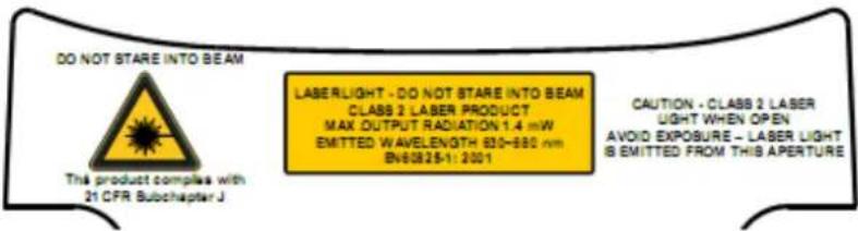
text_image
DO NOT STARE INTO BEAM This product complies with 21 CFR Subchapter J LASERLIGHT - DO NOT STARE INTO BEAM CLASS 2 LASER PRODUCT MAX OUTPUT RADIATION 1.4 mW EMITTED WAVELENGTH 830-880 nm BN60825-1: 2001 CAUTION - CLASS 2 LASER LIGHT WHEN OPEN AVOID EXPOSURE - LASER LIGHT IS EMITTED FROM THIS APERTURE| IDFE | |||
| LA LUCE LASER È VISIBILEALL'OCCHIO UMANO E VIENEEMESSA DALLA FINESTRAINDICATA NELLA FIGURA. | DIE LASER-STRAHLUNG ISTFÜR DAS MENSCHLICHE AUGESICHTBAR UND WIRD AMSTRAHLAUS-TRITTSFENTSTER AUSGESEN-DET (SIEHE BILD) | LE RAYON LASER EST VISIBLEÀ L'OEUIL NU ET IL EST ÉMISPAR LA FENÊTRE DÉSIGNÉESUR L'ILLUSTRATION DANS LAFIGURE | LA LUZ LÁSER ES VISIBLE ALOJO HUMANO Y ES EMITIDAPOR LA VENTANA INDICADAEN LA FIGURA. |
| LUCE LASER NON FISSARE ILFASCIOAPPARECCHIO LASER DICLASSE 2 MASSIMA POTENZAD'USCITA:LUNGHEZZA D'ONDA EMESSA:CONFORME A EN 60825-1(2001) | LASERSTRAHLUNG NICHT INDEN STRAHL BLICKENPRODUKT DER LASERKLASSE2 MAXIMALE AUSGANGSLEISTUNG:WELLENLÄGE:ENTSPR. EN 60825-1 (2001) | RAYON LASER EVITER DEREGARDER LE RAYON APPAREIL LASER DE CLASSE 2 PUISSANCE DE SORTIE:LONGUER D'ONDE EMISE:CONFORME A EN 60825-1(2001) | RAYO LÁSER NO MIRAR FIJOEL RAYO APARATO LÁSER DECLASE 2 MÁXIMA POTENCIADE SALIDA:LONGITUD DE ONDA EMITIDA:CONFORME A EN 60825-1(2001) |
ENGLISH
The following information is provided to comply with the rules imposed by international authorities and refers to the correct use of your terminal.
STANDARD LASER SAFETY REGULATIONS
This product conforms to the applicable requirements of both CDRH 21 CFR 1040 and EN 60825-1 at the date of manufacture.
For installation, use and maintenance, it is not necessary to open the device.

Use of controls or adjustments or performance of procedures other than those specified herein may result in exposure to hazardous visible laser light.
WARNING
The product utilizes a low-power laser diode. Although staring directly at the laser beam momentarily causes no known biological damage, avoid staring at the beam as one would with any very strong light source, such as the sun. Avoid allowing the laser beam to hit the eye of an observer, even through reflective surfaces such as mirrors, etc.
ITALIANO
The POWERSCAN ^® PM8500 Hand-Held Reader is not user-serviceable. Opening the case of the unit can cause internal damage and will void the warranty.
Power Supply
This device is intended to be supplied by a UL Listed or CSA Certified Power Unit marked "Class 2" or "LPS" output rated 5-30 V, minimum 0.75 A which supplies power directly to the scanner via the jack connector on the cable.
WEEE Compliance

Waste Electrical and Electronic Equipment (WEEE) Statement
English
For information about the disposal of Waste Electrical and Electronic Equipment (WEEE), please refer to the website at www.scanning.datalogic.com.
Italian
The PowerScan® PM8500 cordless handheld Reader Family packs a lot of performance into an attractive, rugged, handheld device. It operates in commercial and industrial environments as well as the front office.
In all applications where mobility is a value, the PowerScan® PM8500 represents the key to increase productivity and flexibility in the working area. PowerScan® PM8500 communicates through a low power, license free radio in the 433 MHz band (910 MHz for USA version) and allows bi-directional communication between the base station and the host. PowerScan® PM8500 also includes a display and a 3-key keypad. Thanks to these features, the operator can receive information from the host, interact with the central system and visualize the code read. The cordless system offers scalable solutions to solve simple applications and complex projects:
- Point to point: each reader is associated with its own base station;
- Multipoint: up to 32 readers transmit data to one base station;
- Network: to cover a wide area, connecting up to 16 bases and 512 readers simultaneously working in automatic roaming.
PowerScan ^® PM8500 is 100% compatible with STAR-System ^™ , the Datalogic RF narrow band solution for mobile applications that provides the widest family of narrow band devices on the market. In addition, the main feature of PowerScan PM8500 are:
| Omni-directional Operating | To read a symbol, simply aim at the code and pull the trigger. Since PowerScan® PM8500 is a powerful omni-directional reader, the orientation of the symbol is not important. |
| Decoding and Imaging | Thanks to powerful algorithms, PowerScan® PM8500 reliably decodes all major 1D (linear) barcodes, 2D stacked codes (such as PDF417), 2D matrix symbols (such as DataMatrix), postal codes (such as POSTNET, PLANET). The data stream — acquired from decoding a symbol — is rapidly sent to the host. The reader is immediately available to read another symbol. |
| Flash Memory | Flash technology allows upgrade of the PowerScan® PM8500 reader as new symbologies are supported or as improved decoding algorithms become available. |
| USA Driver License Parsing | The PowerScan® PM8500 reader can be set up to select and output a subset of data elements from USA Driver License PDF417 barcodes. This feature can be enabled using either Datalogic AladdinTM or the barcodes in the USA Driver License Parsing Quick Reference Guide (QRG), available on the Datalogic website. |
Your PowerScan® reader is supplied with its own Quick Reference Guide, which provides connection, diagrams, reading diagrams, basic application parameter settings, default values, and specific technical features. You can use either the Quick Reference Guide or this Manual for initial configuration in order to set the default values and select the interface for your application. This manual provides all the necessary information for complete mechanical installation and system software configuration.
General View
Powerscan® M8500 Readers
Figure 2. PowerScan ^® M8500 Readers

text_image
LEDs POWERSCAN® M8500 Battery Cover TriggerFigure 3. PowerScan ^® M8500 Reader with Display

text_image
PowerScan Display Keypad LEDsBC-80X0 / C-8000 CRADLES
Figure 4. BC-8000
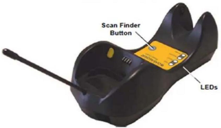
text_image
Scan Finder Button LEDsThe label on the cradle contains LED indicators and a scan finder button. When the button is pressed, the cradle transmits a “broadcast” message. All properly configured scanners (Radio RX Timeout set to keep the radio “awake”) linked to that base (through a bind or a join sequence) and within radio range coverage will emit a beep sequence once every 2 seconds for 30 seconds. A scanner is considered to be linked when the last transmission ends properly.
The scan finder works only in stand-alone layout (point to point or multiple readers).
Figure 5. Figure D - C-8000
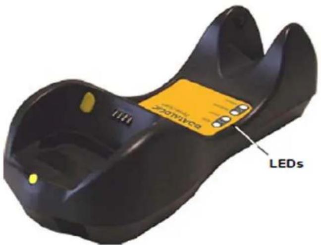
text_image
ZONIMYCS LEDsUsing the Reader
Aiming System
The PowerScan® M8500 reader uses an intelligent aiming system similar to those on cameras. By partially pulling the trigger, the aiming system indicates a field of view to be positioned over the code:
Figure 6. Aiming System

natural_image
Simple geometric shape with a red diamond at center and corner corners (no text or symbols)When you pull the trigger completely a red beam illuminates the code. If the aiming system is centered and the entire symbology is within the aiming system, you will get a good read. The field of view changes size as you move the reader closer or farther away from the code.
Figure 7. Relative Size and Location of Aiming System Pattern
Linear barcode 2D Matrix symbol

text_image
Barcode image with red circular symbol in center, surrounded by red corner markers
text_image
QR code image with red square overlay and corner red corner markersThe field of view indicated by the aiming system will be smaller when the PowerScan® PM8500 is closer to the code and larger when it is farther from the code. Symbologies with smaller bars or elements (mil size) should be read closer to the unit. Symbologies with larger bars or elements (mil size) should be read farther from the unit. (See "Technical Features" starting on page 179 for further details).
Normal Operation
PowerScan® M8500 normally functions by capturing and decoding codes.
Point the reader at the target and pull the trigger partially to enable the aiming system. Then, pull it completely to capture and decode the image. The reader will repeatedly flash until the symbol is decoded or timeout is reached. In between the flashes of the reader, the aiming system keeps on showing the field of view on the target (see Figure 7 on page 18).
As you are reading code symbols, adjust the distance at which you are holding the reader.

The PowerScan ^® M8500 hand-held reader aiming system is designed for general reading and decoding of 1D and 2D symbols. Some variation in reading distance will occur due to narrow bar width and other factors.

If reading codes positioned on reflective surfaces, it may be necessary to tilt the reader with respect to the barcode and/or set the Camera Control parameters (see page 102).
Configuration Methods
Reading Configuration Codes
This manual can be used for complete setup and configuration. If you wish to change the default settings, you can configure the PowerScan® PM8500 reader by reading the programming code symbols in this manual. Configuration commands and their relative arguments are read individually using the symbols in this manual. See "Configuration Using Code Symbols" starting on page 53.
Using Datalogic Aladdin™
Datalogic Aladdin ^™ is a multi-platform utility program providing a quick and user-friendly configuration method via the RS-232/USB-COM interface. Aladdin, available on the CD-ROM provided, allows you to program the reader by selecting configuration commands through a user-friendly graphical interface running on a PC. These commands are sent to the reader over the current communication interface, or they can be printed as barcodes to be scanned.
It also provides the ability to perform a software upgrade for the connected device (see the Datalogic Aladdin™ Help On-Line for more details).
Sending Configuration Strings from Host
An alternative configuration method is provided in Appendix B, Host Configuration Strings using the RS-232 or USB COM interface. This method is particularly useful when many devices need to be configured with the same settings. Batch files containing the desired parameter settings can be prepared to configure devices quickly and easily.
The PowerScan ^® M8500 reader incorporates a multi-standard interface, which can be connected to a Host by plugging the correct interface cable into the connector and closing the cable cover.
Autoscanning
Normal Mode
PowerScan® M8500 provides an autoscan command (see page 205), which when enabled, causes the reader to scan continuously and to monitor the central zone of its reading area. In this way, PowerScan® M8500 is ready to capture any image (containing a potential code) positioned on a uniform background.
The aiming system can be enabled to indicate the reading area of the potential code to be captured. The illumination system can also be enabled when the ambient light conditions are not sufficient to autodetect the potential code to be captured; furthermore, the illumination system increases in intensity for an instant when capturing and decoding an image. A safety time may be defined to prevent PowerScan® M8500 from reading the same code repeatedly.
If the decoding is completed successfully, the reader starts monitoring the reading area again. In case of decoding failure, PowerScan® M8500 keeps on decoding until a potential code is present in the central zone of the reading area.
Pattern Mode
The Autoscan pattern mode is particularly advised when reading barcodes positioned on a non-uniform background. In these cases PowerScan® M8500 may perceive some elements of the background as barcodes and start the decoding. To avoid this undesired effect, the Autoscan Pattern Code is placed in the PowerScan® M8500 reading area which prevents decoding. Using this code as the background, code reading takes place normally by presenting desired codes to be read over the Pattern Code. Between each code read, the Pattern Code must be presented to the reader.
The Pattern Code can be printed from this manual (see Autoscan Pattern Code in Appendix F).
In case of low ambient light conditions, PowerScan® M8500 automatically activates the illumination system. If desired, the illumination system can be enabled so that it is always active.
Camera Control
Exposure and Calibration
Three automatic control modes are available to optimize the reading performance:
- A utomatic based on entire image: camera control mode based on the analysis of the whole image. This mode works well in most standard applications. It is the default setting.
- Au tomatic based on central image: camera control mode based on the analysis of a restricted area positioned in the central zone of the image. This mode is suggested when reading small codes positioned in a dark and extensive background.
- A automatic for highly reflective surfaces: camera control mode allowing reading of codes on highly reflective surfaces. This mode is suggested, for example, when reading codes positioned on plastic or metal surfaces.
Refer to CAMERA CONTROL on page 102 for configuration codes.
Defining Data Formatting
The string of a decoded code to be sent to the host may be formatted as follows:
• defining simple data formatting (see page 84)
- defining advanced data formatting giving complete flexibility in changing the format of data (see Advanced Data Formatting on page 135).
When both simple and advanced data formatting are selected the info is processed in the following order:
- the string of the decoded code is processed according to the advanced formatting rules;
- the resulting string is processed according to the selection type rules of the simple data formatting;
- character substitution is performed on the resulting string;
- character deletion is performed on the resulting string;
- code concatenation is performed;
- code ID is attached to the resulting string;
- global headers and terminators are attached to the resulting string;
The codes to be sent to the host may also be selected or ordered depending on the following two conditions:
One Code Per Scan
- PowerScan® M8500 sends the code being closest to the image center. If the "Central Code Transmission" command is enabled, only the code containing the image center will be transmitted (see page 205);
All Codes Per Scan
- The codes to be sent to the host may be ordered either by length or by symbology starting from the code being closest to the image center (see page 205). When enabling both these criteria, codes belonging to the same symbology are sent to the host depending on their length.
Concatenation
It is possible to concatenate up to 4 different codes, set their length and enable the Intercode Delay between them (the intercode delay is set in the specific interface parameters, see "Configuration Using Code Symbols" starting on page 53). When enabling the delay one or more global headers and terminators are added to the decoded data. The concatenation procedure may occur in different ways depending on the number of codes to be decoded per image:
One Code Per Scan
- If the code resulting from the single decoding of an image belongs to one of the code families to be concatenated, it is saved to the PowerScan® M8500 memory waiting for other codes to complete the concatenation.
- If the code belongs to the same family of a code previously saved, it overwrites the old one.
- If the code resulting from the decoding does not belong to one of the code families to be concatenated, it causes the concatenation failure and clears the temporary memory. If the "Concatenation Failure Transmission" command is set to "Tx codes causing failure" (see page 100), this code will be sent in the output message.
All Codes Per Scan
- All codes resulting from the decoding of an image and belonging to one of the families to be concatenated are saved to the PowerScan® M8500 memory waiting for other codes to complete the concatenation.
- If one or more codes resulting from the decoding belong to the same family of codes previously saved, they overwrite the old ones.
- When the image contains no code to be concatenated, the concatenation fails and the reader temporary memory is cleared. If the "Concatenation Failure Transmission" command is set to "Tx codes causing failure" (see page 100), the codes causing the concatenation failure will be sent in the output message.
Package Contents
The following parts are included in the PowerScan® PM8500 package contents:
• PowerScan® PM8500 Hand-Held Reader
- CD-ROM containing the PowerScan® PM8500 Configuration Tools software and PowerScan® PM8500 Reference Manual
• PowerScan® PM8500 Quick Reference Manual
You may want to save your packing material in case you need to ship the reader at some later time.
Installation
BC-80X0 Interface Cable Connections
The BC-80X0 incorporates a multi-standard interface, which can be connected to a Host by simply plugging the correct interface cable into the Host connector, placed on the base of the cradle. In addition the cradle must be connected to an external power supply.
Figure 8. BC-80X0 Connectors
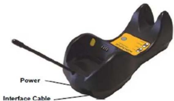
text_image
Power Interface CableFigure 9. Disconnecting the BC-80X0 Cable

natural_image
Close-up of a black robotic device with a circular highlight and directional arrows indicating movement or force (no text or symbols)To disconnect the cable, insert a paper clip or other similar object into the hole corresponding to the Host connector on the body of the cradle.
Push down on the clip while unplugging the cable.
RS-232 Connection

USB

IBM USB POS
WEDGE Connection

PEN Emulation Connection
Network Connections
BC-8060 Network Connectors
The multidrop network is a bus system which is propagated from one BC-8060 cradle to another using individual cables. This is possible thanks to the RS-485 connector on the front panel of the cradle.
Figure 10. Network Connectors
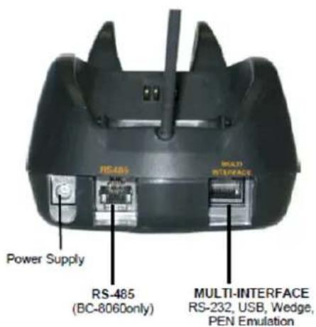
text_image
RS-485 Power Supply RS-485 (BC-8060only) MULTI-INTERFACE RS-232, USB, Wedge, PEN EmulationAll cradles are connected together within the bus system through the Datalogic RS-485 splitter cable (CAB-428, part number 90A051950), which must be inserted in the RS-485 cradle connector.
Cable length should be kept to a minimum, as with all bus systems.
Network Cabling
The Multidrop line is made using RJ45 connectors and a cable having the following specifications:
• twisted pair AWG 24 wires
- 120 Ω im pedance
• maximum network cable length 1200 meters
Pin Function
| 1 RS-485 + | |||
| 2 RS-485 - | |||
| 3 | N | . | C |
| 4 | V | D | C |
| 5 | V | D | C |
| 6 | N | . | C |
| 7 | V | D | C |
| 8 | V | D | C |

text_image
Multidrop Cables Pin 1 Data and Power Supply Data only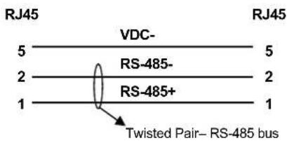
text_image
RJ45 VDC- 5 RS-485- 2 RS-485+ 1 1 RJ45 5 2 2 1 Twisted Pair– RS-485 bus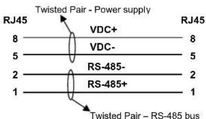
text_image
Twisted Pair - Power supply RJ45 8 VDC+ 8 VDC- 5 2 RS-485- 2 RS-485+ 1 1 RJ45 Twisted Pair - RS-485 busWhen wiring the multidrop cables, note the following:
- Pin 8 (or 7) can be connected only if the power has to be propagated from a cradle to a STARGATE™ base station or STAR-Box™ converter via the cable.
- Pins 5 (or 4) should always be connected as r eference ground.
• To avoid excessive voltage drop, it is recommended not to propagate power between BC-8060 cradles when used as battery chargers but to supply each cradle individually. The total number of devices, which can be connected to a single power supply, depends on the power supply voltage, the wire length and resistance and therefore the voltage drop. Do NOT connect VDC+ between network devices that are individually powered.
Network Termination
The first and last cradles of the chain (the two ends of the bus) must be properly terminated. The cradle has an internal terminator that can be selected via jumper. For this selection you must open the device.
Figure 11. Terminator for Multidrop Network

text_image
No Termination Static DynamicStatic termination works for all network configurations. However, the network is always under load even when no data transmission takes place.
Dynamic termination can be used for baud rates at or above 38400 and provides less load on the network when idle.
PowerScan® M8500 Battery Maintenance
Battery Charging
Once the system is connected and powered, you can place the PowerScan ^® M8500 into the cradle to charge the battery.
When the reader is correctly inserted in the cradle, the "Reader" red LED on the cradle goes on to indicate that the battery is charging. The "Reader" green LED on the cradle goes on when the battery is completely charged.

natural_image
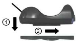
Close-up of a handheld electronic device with black body, yellow clasp, and antenna (no visible text or symbols)Replacing PowerScan® M8500 Batteries
- To change the battery pack in your PowerScan ^ M8500 scanner, push the Release Button as indicated by Arrow 1 and extract the battery pack from the reader handle.

natural_image
Two-step illustration of a handheld barcode scanner, showing step 1 and step 2 with arrows indicating direction (no text or symbols on device)
When the batteries are extracted from the scanner, the timer maintains the current hour and date for about 1 minute.
- Then, insert the new battery pack into the reader handle until a 'click' is heard and the Release Button moves back to its neutral position.

WARNING
Do not discharge the battery using any device except for the scanner. When the battery is used in devices other than the designated product, it may damage the battery or reduce its life expectancy. If the device causes an abnormal current to flow, it may cause the battery to become hot, explode or ignite and cause serious injury.
Lithium-ion battery packs may get hot, explode or ignite and cause serious injury if exposed to abusive conditions. Be sure to follow the safety warnings listed below:
- Do not place the battery pack in fire or heat.
- Do not connect the positive terminal and negative terminal of the battery pack to each other with any metal object (such as wire).
- Do not carry or store the battery pack together with metal objects.
- Do not pierce the battery pack with nails, strike it with a hammer, step on it or otherwise subject it to strong impacts or shocks.
- Do not solder directly onto the battery pack.
- Do not expose the battery pack to liquids, or allow the battery to get wet.
- Do not apply voltages to the battery pack contacts.
In the event the battery pack leaks and the fluid gets into your eye, do not rub the eye. Rinse well with water and immediately seek medical care. If left untreated, the battery fluid could cause damage to the eye.

CAUTION
Always charge the battery at 32^-104^ ( 0^-40^ ) temperature range.
Use only the authorized power supplies, battery pack, chargers, and docks supplied by your Datalogic reseller. The use of any other power supplies can damage the device and void your warranty.
Do not disassemble or modify the battery. The battery contains safety and protection devices, which, if damaged, may cause the battery to generate heat, explode or ignite.
Do not place the battery in or near fire, on stoves or other high temperature locations.
Do not place the battery in direct sunlight, or use or store the battery inside cars in hot weather. Doing so may cause the battery to generate heat, explode or ignite. Using the battery in this manner may also result in a loss of performance and a shortened life expectancy.
Do not place the battery in microwave ovens, high-pressure containers or on induction cookware.
Immediately discontinue use of the battery if, while using, charging or storing the battery, the battery emits an unusual smell, feels hot, changes color or shape, or appears abnormal in any other way.
Do not replace the battery pack when the device is turned on.
Do not remove or damage the battery pack's label.
Do not use the battery pack if it is damaged in any part.
Battery pack usage by children should be supervised.
As with other types of batteries, Lithium-Ion (LI) batteries will lose capacity over time. Capacity deterioration is noticeable after one year of service whether the battery is in use or not. It is difficult to precisely predict the finite life of a LI battery, but cell manufacturers rate them at 500 charge cycles. In other words, the batteries should be expected to take 500 full discharge/charge cycles before needing replacement. This number is higher if partial discharging / recharging is adhered to rather than full / deep discharging,
The typical manufacturer advertised useful life of LI batteries is one to three years, depending on usage and number of charges, etc., after which they should be removed from service, especially in mission critical applications. Do not continue to use a battery that is showing excessive loss of capacity, it should be properly recycled / disposed of and replaced. For most applications, batteries should be replaced after one year of service to maintain customer satisfaction and minimize safety concerns.
Collect and recycle waste batteries separately from the device in compliance with European Directive 2006/66/EC, 2002/95/EC, 2002/96/EC and subsequent modifications, US and China regulatory and others laws and regulations about the environment.
Mounting The BC-80X0 / C-8000 Cradle
The cradle package contains the following items:
• BC-80X0 / C-8000 Cradle
• BC-80X0 Quick Reference / C-8000 Quick Reference
• BC-8000 Antenna • 2 wall-mounting lock hinges
• 2 adhesive strips • 4 rubber feet
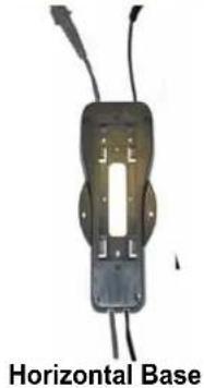
- 1 horizontal base • 1 inclined base
The cradle (either BC-80X0 or C-8000) can be mounted for portable or fixed desktop usage, or it can be fixed to a wall. The horizontal base allows portable and fixed desktop usage, while the inclined base provides desktop and wall mounting guaranteeing a comfortable handling of the PowerScan® M8500 reader.
Figure 12. BC-80X0/C-8000 Cradle mounted on the Horizontal Base

natural_image
Black and yellow object resembling a medical or anatomical device with a protruding rod (no text or symbols visible)Figure 13. BC-80X0/C-8000 Cradle mounted on the Inclined Base

natural_image
Two black mechanical components with wires, shown from different angles (no text or symbols visible)Desktop Mounting
For desktop usage, you can mount the cradle either on the horizontal base, for reduced overall dimensions, or on the inclined base for a more ergonomic removal and insertion of the reader onto the cradle.
Figure 14. Horizontal base

text_image
Mounting Tabs (4) Mounting Holes (2) Top View
text_image
Rubber Foot Seat (4) Adhesive Strip Seat (2) Cable Channels Bottom ViewFigure 15. Inclined base
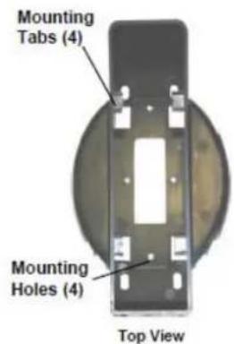
text_image
Mounting Tabs (4) Mounting Holes (4) Top View
text_image
Adhesive Strip Seat (2) Rubber Foot Seat (4) Cable Channels Bottom ViewPortable Desktop Use
- Correctly position the BC-80X0/C-8000 onto the base by sliding it along the mounting tabs until aligned.
text_image
Diagram showing a mechanical component with labeled parts and directional arrows indicating motion or force
natural_image
3D diagram of a mechanical component with two directional arrows indicating movement or force (no text or symbols)- Carefully clean the rubber foot seats of the base to remove any impurities that could reduce adhesion.
- Remove the protective plastic from the rubber feet and stick them onto the bottom surface of the base.
- If mounting the BC-80X0 cradle, insert the antenna in the appropriate hole on the body of the cradle and screw it clockwise until tight.
Fixed Desktop Use
For fixed desktop installation, use the adhesive strips or fixing screws (not provided) according to your needs.
For mounting with adhesive strips:
- Position the cradle onto the base by sliding it along the mounting tabs until aligned.
- Carefully clean the adhesive strip seats of the base to remove any impurities that could reduce adhesion.
- Remove the protective plastic from one side of the adhesive strips and stick them onto the base surface.
- Position the cables to be connected to the BC-80X0/C-8000 cradle along the dedicated channels, as shown in the figures below:
natural_image
Horizontal base electronic component with wires and a central slot (no text or symbols visible)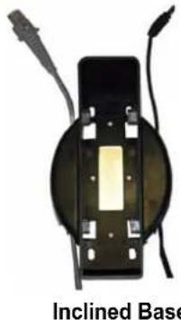
natural_image
Close-up of an inclined base component with wires and connectors (no text or symbols visible)-
Remove the plastic from the other side of the strips and affix the base to the table.
-
If mounting the BC-80X0 cradle, insert the ante nna in the appropriate hole on the body of the cradle and screw it clockwise until tight.
For mounting with screws:
- Position the cables to be connected to the BC-80X0/C-8000 cradle along the dedicated channels, as shown in the figures below:
- Position the base on the table and affix it by means of the screws (not provided).
- Position the cradle on the base by sliding it along the mounting tabs until aligned.
- If mounting the BC-80X0 cradle, insert the antenna in the appropriate hole on the body of the cradle and screw it clockwise until tight.
Wall Mounting

natural_image
Black and yellow object resembling a stylized microphone or antenna, no visible text or symbols- Remove the yellow caps and insert the two wall mounting lock hinges provided with your cradle.

natural_image
Close-up of a hand holding a yellow object with a circular highlight, next to a close-up of a black mechanical component (no visible text or symbols)-
Position the cables to be connected to the BC-80X0/C-8000 cradle along the dedicated channels (see figures on page 32.)
-
Complete the procedure using one of the following two methods:
If using the adhesive strips:
- Carefully clean the adhesive strip seats of the base to re move any impurities that could reduce adhesion.
- Remove the protective plastic from one side of the adhesive strips and stick them onto the base surface.
- Remove the plastic from the other side of the strips and affix the base to the wall as indicated in the figure below.
If using the mounting screws:
- Using the mounting holes on the base as a pattern, mark the wall where you desire to mount the BC-80X0/C-8000.
- Drill the appropriate size holes and insert the threaded dowels (not provided) into the holes.
- Position the base on the wall as indicated in the figure below and affix it by means of the screws (not provided).
Figure 16. Inclined Base Wall-Mounting

natural_image
Black plastic object with a pointed tip and side profile (no text or symbols visible)- Attach the cradle on the base by sliding it along the mounting tabs until aligned.
- If mounting the BC-80X0 cradle, insert the antenna in the appropriate hole on the body of the cradle and screw it clockwise until tight.
There are two basic system layouts that can be employed: Stand-alone systems (including Point-to-Point layouts) and Multidrop STAR-System™ Networks.
System and Network Layouts
Stand-Alone Layouts
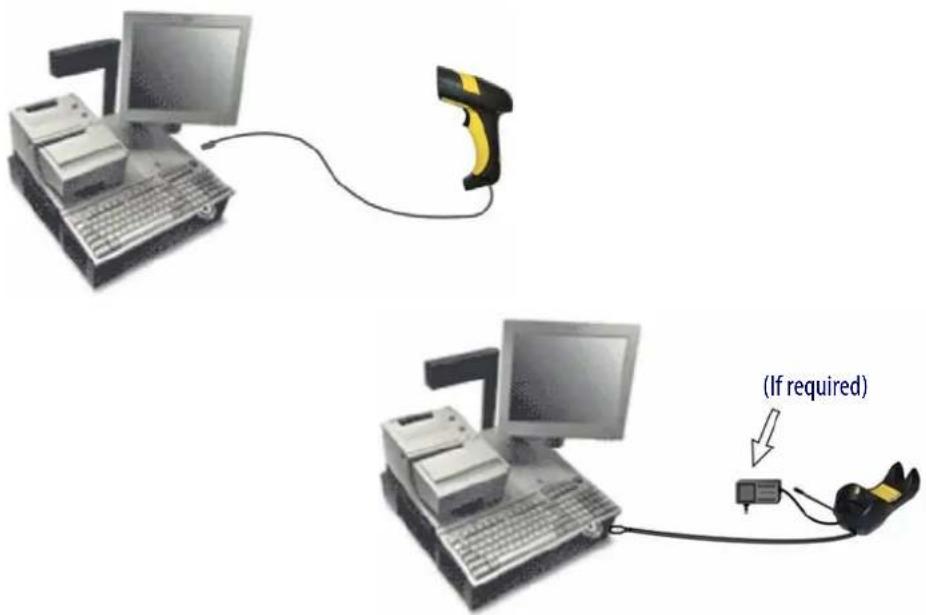
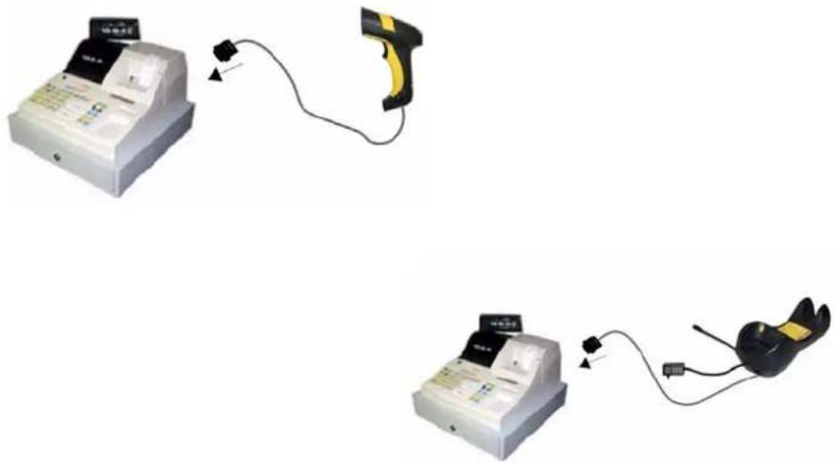
Figure 17. Point-to-Point Reader Layout
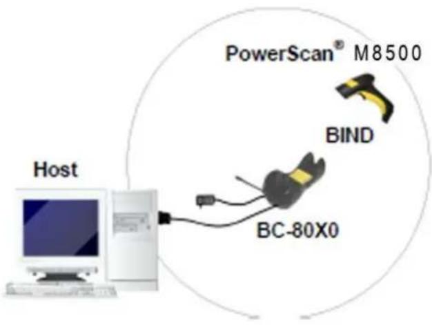
text_image
PowerScan® M8500 BIND BC-80X0 HostFigure 18. Stand-Alone Layout with Multiple Readers
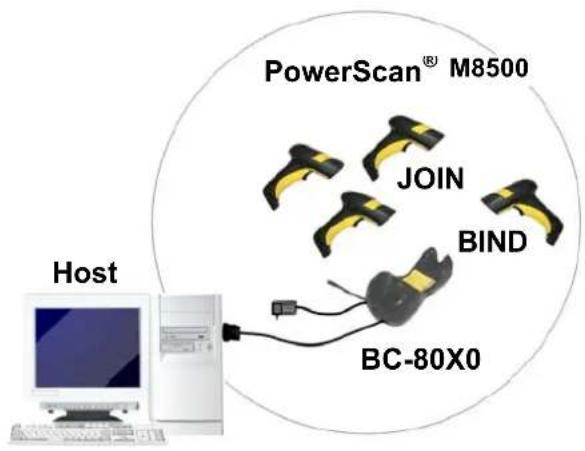
flowchart
graph TD
    A["Host"] --> B["PowerScan® M8500"]
    B --> C["JOIN"]
    B --> D["BIND"]
    B --> E["BC-80X0"]
In stand-alone systems, each cradle is connected to a single Host.
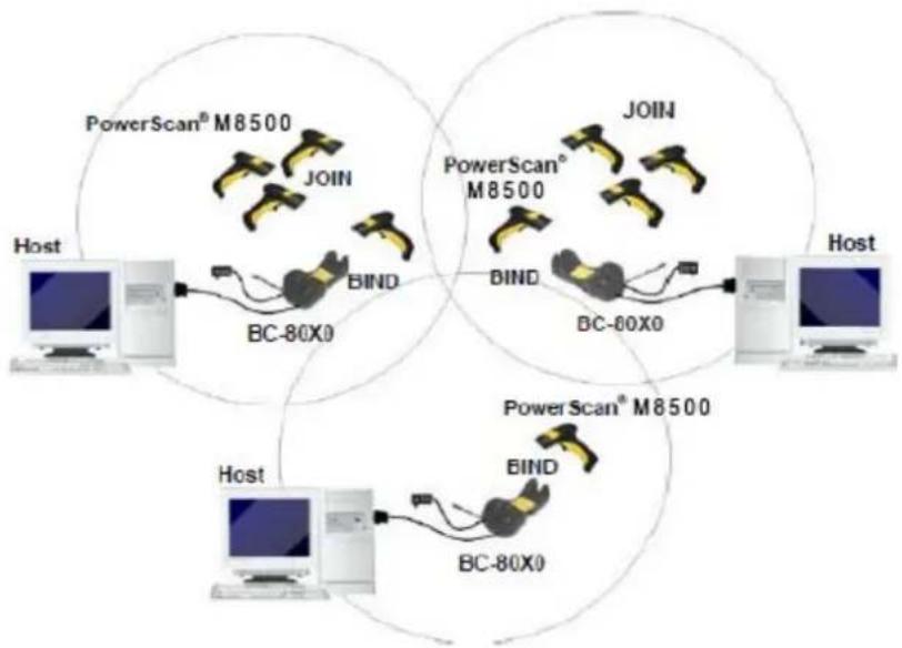
Multiple Stand-Alone Layouts
Many stand-alone connections can operate in the same physical area without interference, provided all readers and cradles in the system have different addresses.
Figure 19. Multiple Stand-alone Systems in the Same Area
flowchart
graph TD
    subgraph Host
        A["Computer"] --> B["BC-80X0"]
        B --> C["PowerScan® M8500"]
        C --> D["BOOT"]
        D --> E["BC-80X0"]
        E --> F["PowerScan® M8500"]
        F --> G["BOOT"]
        G --> H["BC-60X0"]
        H --> I["PowerScan® M8500"]
        I --> J["BOOT"]
    end
    subgraph PowerScan® M8500
        K["Computer"] --> L["BC-80X0"]
        L --> M["PowerScan® M8500"]
        M --> N["BOOT"]
        N --> O["BC-60X0"]
        O --> P["PowerScan® M8500"]
        P --> Q["BOOT"]
    end
    style Host fill:#f9f,stroke:#333
    style PowerScan® M8500 fill:#ccf,stroke:#333
    style BC-80X0 fill:#cfc,stroke:#333
    style PowerScan® M8500 fill:#fcc,stroke:#333
Since the cradles can communicate to multiple PowerScan ^® M8500 readers, you might find it useful to employ one or more C-8000 battery chargers in addition to the BC-80X0 cradle, so that the battery re-charging operation can be performed for several scanners at the same time.
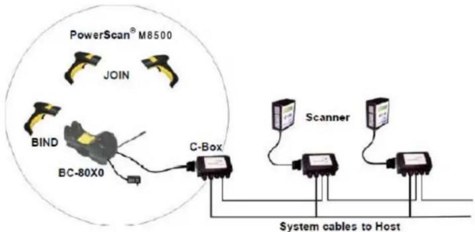
Figure 20. C-BOX Layout
flowchart
graph TD
    A["PowerScan® M8500"] --> B["JOIN"]
    B --> C["BIND"]
    C --> D["BC-80X0"]
    D --> E["C-Box"]
    E --> F["Scanner"]
    F --> G["System cables to Host"]
    style A fill:#f9f,stroke:#333
    style B fill:#f9f,stroke:#333
    style C fill:#f9f,stroke:#333
    style D fill:#f9f,stroke:#333
    style E fill:#ccf,stroke:#333
    style F fill:#ccf,stroke:#333
    style G fill:#ccf,stroke:#333
In this layout the BC-80X0 cradle is connected by a dedicated cable using the RS-232 interface to a C-BOX connection box as part of a fixed scanner network. This allows the flexibility of a hand-held reading station integrated into a variety of fixed scanning applications so that all readers (both fixed and hand-held), in the system provide communications to the Host.
The various C-BOX models provide many interface types for the Host system such as RS-232, RS-485, and Profibus.
Multidrop STAR-System™ Network Layouts
Even though many stand-alone systems can operate in the same physical area without interfering with each other, it may be desirable to bridge data from multiple base stations in a network to a single Host. PowerScan® M8500 readers are compatible with STAR-System™ networks. These networks provide seamless active roaming for any RF reading device in the system.
Host Master Layout
Figure 21. Example of Multidrop STAR-System™ Network with Host as Master

flowchart
graph TD
    A["Computer"] -->|RS-232| B["Internal Termination"]
    B -->|RS-485 + VDC| C["Internal Termination"]
    C -->|RS-485 Only| D["CAB-428 Splitter"]
    D -->|RS-485 + VDC| E["Internal Termination"]
    style A fill:#f9f,stroke:#333
    style B fill:#ccf,stroke:#333
    style C fill:#cfc,stroke:#333
    style D fill:#fcc,stroke:#333
    style E fill:#ffc,stroke:#333
A. Host Master with STAR-Link™
B. STAR-Box™ converter
C. BC-8060 slave cradles
D. STARGATE™ base stations
In this layout the Host acts as the Master using STAR-Link™ software. The Host is connected in RS-232 to a STAR-Box™ converter, which is connected to the first slave in the RS-485 network. In this way the base stations provide communications between a single Host and all readers in the system. STARGATE™ base stations are used as slaves in this network. The Slaves at the ends of the network must be terminated (reference the STARGATE™ and STAR-Box™ Installation Manuals and "Network Termination" on page 27).
See "PowerScan® M8500/STAR-System™ Setup" on page 43 and "BC-8060 STAR-System™ Network Setup" on page 45, or the Datalogic Aladdin™ Help On-Line, for system configuration specifications.
BC-8060 Master Layout
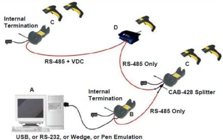
Figure 22. Example of Multidrop STAR-System™ Network with BC-8060 as Master
flowchart
graph TD
    A["USB, or RS-232, or Wedge, or Pen Emulation"] --> B["Internal Termination"]
    B --> C["RS-485 Only"]
    B --> D["RS-485 + VDC"]
    D --> E["CAB-428 Splitter"]
    E --> F["Internal Termination"]
    F --> G["RS-485 Only"]
    style A fill:#f9f,stroke:#333
    style B fill:#ccf,stroke:#333
    style C fill:#cfc,stroke:#333
    style D fill:#fcc,stroke:#333
    style E fill:#cff,stroke:#333
    style F fill:#ffc,stroke:#333
    style G fill:#fcc,stroke:#333
A. Host
B. BC-8060 Master cradle
C. BC-8060 Slave cradles
D. STARGATE™ base station
In this layout a BC-8060 cradle acts as the Master. The Host is connected to the BC-8060 Master using any one of the multi-standard interfaces (RS-232, USB, WEDGE, or PEN Emulation). The Master is then connected to the slaves in the RS-485 network. In this way the slave cradles provide communications between a single Host and all readers in the system. STARGATE™ base stations can also be used as slaves in this network. The devices at the ends of the network must be terminated (see "Network Termination" on page 27).
See "PowerScan® M8500/STAR-System™ Setup" on page 43 and "BC-8060 STAR-System™ Network Setup" on page 45, or the Datalogic Aladdin™ Help On-Line, for system configuration specifications.
Master BC-8060 Network Troubleshooting
Two diagnostic strings can be sent via RS-232 from the Host to the Master cradle in order to have feedback about the network itself.
#+LSlave
Returns a list of all the Slaves recognized at boot up.
Example: In a network where the Master cradle has address 0188 and one Slave cradle with address 0001, the response is:
188
1
#+Alive
Executes a continuous Alive request to the slave xxxx in order to monitor the performance of the connection. A diagnostic message is displayed on the Host.
Example: If this command is sent for slave cradle with address 0032, the response is:
/*32: BC-80X0 SOFTWARE RELEASE 1.00 20/10/2006*/
if there are no communication errors
/\*32: FAIL\*/
if there are communication errors.
To exit from this command, reset the system by cycling power to the Master cradle.
Setup Procedures
For PowerScan ^® M8500 Series readers, the setup procedures depend on two basic applications, Stand-alone or STAR-System ^™ .
Stand-alone applications allow communication with the Host by either the BC-80X0 cradle (page 40), or by the STAR-Modem ^TM radio modem (page 42).
STAR-System ^TM applications allow communication with the Host through an RS-485 network by the STARGATE ^TM RF base station or by the BC-8000 cradle (page 43 and 45).
Proceed as shown in the following diagram:

flowchart
graph TD
    A["Begin Setup by choosing the setup procedure for your PowerScan® reader as indicated below."] --> B["Stand Alone Applications\nPowerScan® M8500/BC-80X0\npage 39\npage 45\nOptional page 45 Step 1\nmultiple readers per BC-8000\nPowerScan® M8500/STAR-Modem™ in Stand Alone Mode"]
    A --> C["STAR-System™ Network Applications\nBC-8000\npage 43"]
    A --> D["STAR-System™ Applications\nPowerScan® M8500/STAR-System™\page 40\n• S T A R G A T E ™\n• BC-8000 Network\n• STAR-Modem™ in STAR-System™ Mode"]
    A --> E["End of Setup\nYour reader is now ready to read barcodes using the default settings."]
PowerScan ^® M8500/BC-80X0 Point-to-Point Setup
A rapid configuration procedure has been devised for point-to-point applications where a single reader is associated exclusively with its own BC-80x0 base station and where it is not necessary to set the Date and Time parameters.
A special pre-printed bind-address label provided in the BC-80x0 base station package can be used to bind the PowerScan ^® M8500 reader to the base station with the address coded on the label. The address is also written numerically on the label to be easily recognized. Valid addresses are in the range from 0000 to 1999. Make sure that all cradles used in the same area have different addresses.
To rapidly configure your point-to-point application:
- Apply the bind-address label onto the BC-80x0 base station as indicated in the BC-80x0 Quick Reference Guide.
-
When the BC-80X0 cradle is connected and powered, read the Bind-Address label to pair the PowerScan ^* M8500 to the BC-80X0 cradle.
The green LED on the PowerScan ^® M8500 will blink: the reader is ready to be positioned onto the cradle. -
Firmly position the reader onto the cradle within 10 seconds, a beep will be emitted, signaling that the BC-80X0 cradle has been paired to the PowerScan ^® M8500, and the green LED on the reader will go off.

natural_image
Close-up of a black handheld device with yellow and white latches, no visible text or symbolsIf it ever becomes necessary to change the reader, just read the bind-address label applied to the cradle and position the new reader onto the cradle.
Do not use multiple readers with this configuration method.
- Configure the BC-80X0 cradle; refer to the "BC-80X0 Quick Reference Guide".
END of procedure. YOUR READER IS NOW READY TO READ CODES.
PowerScan ^® M8500/BC-80X0 Stand-Alone Setup
Read the restore default parameters code below.
1.
Restore PowerScan ^® M8500 Default

Follow the procedure below to set the radio address and bind PowerScan ^® M8500 to the BC-80X0 cradle.
2.
Enter Configuration

3.
Set Date

six digits for Day, Month and Year (DDMMYY)
4.
Set Time

four digits for Hour and Minutes (HHMM)
5.
Set Radio Address

+
four digits for the PowerScan ^* M8500 Address (from 0000 to 1999).
All readers used in the same area must have different addresses.
6.
Exit and Save Configuration

- Read the Bind code to pair the PowerScan ^e M8500 to the BC-80X0 cradle. The reader is dedicated to the cradle. Any previously bound reader will be excluded.
To connect several readers to the same cradle see "Using Multiple M-Series Readers with Same Cradle" on page 42
Bind

The green LED on the PowerScan ^® M8500 will blink; the reader is ready to be inserted into the cradle.
- Firmly insert the reader into the BC-80X0 cradle within 10 seconds, a beep will be emitted, signaling that the BC-80X0 cradle has been paired to the PowerScan ^* M8500, and the green LED on the reader will go off.

text_image
green LED- Read the BC-80X0 restore default code:
Restore BC-80X0 Default

Go to "Interface Selection" on page 47.
Using Multiple M-Series Readers with Same Cradle
If you want to use several M-Series readers with the same BC-80X0 cradle, you must first Bind the cradle with one of the readers (see previously described configuration procedure).
Successive readers can be associated with the same cradle by following the configuration procedure substituting the Bind command with Join (see step 7. on page 41).
7.
Join

The green LED on the PowerScan ^® M8500 will blink: the reader is ready to be positioned onto the cradle. Complete step 8. on page 41.
END of procedure.

CAUTION
All readers associated with the same cradle must have different addresses.
YOUR READER IS NOW READY TO READ BARCODES.
To change the defaults see "Configuration Parameters" on page 53.
PowerScan ^® M8500/STAR-Modem ^™ in Stand-Alone Mode
To configure a PowerScan ^® M8500 reader to communicate with STAR-Modem ^™ in Stand-alone Mode, follow the procedure in "PowerScan ^® M8500/BC-80X0 Stand-Alone Setup" on page 40, substituting steps 6 and 7 with those below:
6.
STAR-Modem™ Address

Read the code above and the four-digit address of the STAR-Modem ^™ .
7.
Exit and Save configuration

END of procedure.
YOUR READER IS NOW READY TO READ BARCODES.
To change the defaults see "Configuration Parameters" on page 53.
PowerScan ^® M8500/STAR-System ^TM Setup
The following procedure allows configuring a PowerScan ^® M8500 reader to communicate with various STAR-System ^™ devices such as STARGATE ^™ RF base stations.
1.
Restore PowerScan ^® M8500 Default

2.
Enter Configuration

3.
Set Date

+
six digits for Day, Month and Year (DDMMYY)
4.
Set Time

+
four digits for Hour and Minutes (HHMM)
- Set the connection according to the length of the codes to be read:
Code Length ≤240 Characters

Code Length >240 Characters
(not for systems with BC-8000 as Master)

6.
Set Radio Address

+
four digits from the Numeric Table in the range 0000-1999.
All readers must have different addresses.
7.
First STAR-System™ Address

Read the code above and the four-digit address of the First STAR-System™ device in the system.
8.
Set Last STAR-System™ Address

Read the code above and the four-digit address of the Last STAR-System™ device in the system.

Whenever the system is composed of a single base station, the first and last base station addresses (steps 7 and 8) must have the same value.
9.
Exit and Save Configuration

END of procedure.
YOUR READER IS NOW READY TO READ BARCODES.
To change the defaults see "Configuration Parameters" on page 53.
BC-8060 STAR-System™ Network Setup
When the BC-8060 cradle model is used in an RS-485 network, it must be initially configured. To do this using configuration barcodes, follow the procedure below using any PowerScan ^® M8500 reader.
1.
Set BC-8060 Address

+
four digits for the BC-8060 Address (from 0000 to 1999).
All cradles used in the network must have different addresses.
2.
Exit and Save configuration

- Read the Bind code to pair the PowerScan ^® M8500 to the BC-8060 cradle for configuration.
Bind

The green LED on the PowerScan ^® M8500 will blink; the reader is ready to be inserted into the cradle.
- Firmly insert the reader into the BC-8060 cradle within 10 seconds, a beep will be emitted, signaling that the BC-8060 cradle has been paired to the PowerScan ^® M8500, and the green LED on the reader will go off.

text_image
green LED- Read the BC-8060 restore default code:
- Read the desired Enable Network code.
Enable RS-485 Master

Enable RS-485 Slave

END of procedure.
For Host Master Network Layouts (see page 37), the network configuration parameters can be changed through STAR-Link™ software running on the PC. Star-Link™ software can be downloaded free from the web site: www.scanning.datalogic.com.
For BC-8060 Master Network Layouts (see page 38), the network configuration parameters can be changed either through the Datalogic Aladdin™ configuration software running on the PC or by reading the barcode selections in the Network section of this manual starting on page 79. If using configuration barcodes, it is advised to completely configure the cradles before reconfiguring the PowerScan® M8500 reader (see below).

After completing the BC-8060 cradle configuration and connections in the network, you must reconfigure the PowerScan ^® M8500 reader using the STAR-System ^™ procedure on page 43.
Interface Selection
Read the interface selection code for your application.
RS-232
Standard

POS TERMINALS
Nixdorf Mode A

ICL Mode

Fujitsu

For POS terminal default settings refer to page 174.
PEN

WEDGE
IBM AT or PS/2 PCs

IBM XT

PC Notebook

IBM SURE1

IBM Terminal 3153

IBM TERMINALS 31XX, 32XX, 34XX, 37XX:
To select the interface for these IBM Terminals, read the correct KEY TRANSMISSION code. Select the KEYBOARD TYPE if necessary (default = advanced keyboard).
KEY TRANSMISSION MODE
make-only keyboard

make-break keyboard

WEDGE (continued)
KEYBOARD TYPE
◆ advanced keyboard

typewriter keyboard

ALT MODE
The ALT-mode selection allows barcodes sent to the PC to be interpreted correctly independently from the Keyboard Nationality used. You do not need to make a Keyboard Nationality selection. (Default=NumLock Unchanged).
Make sure the NumLock key on your keyboard is ON.
IBM AT - ALT mode

PC Notebook - ALT mode

WYSE TERMINALS
ANSI Keyboard

PC Keyboard

ASCII Keyboard

VT220 style Keyboard

DIGITAL TERMINALS
VT2xx/VT3xx/VT4xx

USB Configuration
The USB interface is available for BC-80x0 and C-8000 devices and is compatible with the following Operating Systems:
Windows 98 (and later) IBM POS for Windows
Mac OS 8.0 (and later) 4690 Operating System
USB Start-up
As with all USB devices, upon connection, the Host performs several checks by communicating with the device. During this phase normal operations are suspended. Two basic conditions must be met before the device is ready, the correct USB driver must be loaded and sufficient power must be supplied to the reader.
- For all systems, the correct USB driver for the default USB-KBD interface is included in the Host Operating System and will either be loaded automatically or will be suggested by the O.S. and should therefore be selected from the dialog box (the first time only).
Normally the Host supplies sufficient power to the device and the start-up phase ends correctly. (The reader's LED stops blinking and the reader emits the beep OK signal).
In rare cases, if the Host does not supply sufficient power to the device, a dialog box will appear on the Host and the device will be blocked (the reader's LED continues blinking). In this case, disconnect the USB device cable at the Host (the reader's LED stops blinking), and then try a different USB port as indicated by the Operating System message. (The device emits the beep OK signal. You can now read codes).

flowchart
graph TD
    A["Connect device to Host"] -->|reader LED blinks| B["Load drivers (if requested)"]
    B -->|reader LED off - BEEP OK| C["Select desired USB interface code (USB-KBD is default)"]
    C --> D["Load drivers (if requested)"]
    D --> E["Read test codes. Device is READY"]
- At this point you can read the USB interface configuration code according to your application. Load drivers from the O.S. (if requested). When configuring the USB-COM interface, the relevant files and drivers must be installed from the USB Device Installation software, which can be downloaded from the web page http://www.scanning.datalogic.com.
The device is ready. Successive start-ups will automatically recognize the previously loaded drivers.
USB Parameters
USB-KBD

USB-KBD-ALT-MODE

USB-KBD-APPLE

USB-COM*

USB-IBM-Table Top

USB-IBM-Hand Held

* When configuring USB-COM, the relevant files and drivers must be installed from the USB Device Installation software, which can be downloaded from the web site http://www.scanning.datalogic.com.
NOTES
Chapter 3
Configuration Using Code Symbols
This section provides programming barcodes to configure your reader by changing the default settings. For details about additional methods of programming, see "Configuration Methods" on page 19.

You must first enable your reader to read barcodes in order to use this section. If you have not done this, go to Setup Procedures, starting on page 39 and complete the appropriate procedure.
Configuration Parameters
Once the reader is set up, you can change the default parameters to meet your application needs. Refer to "Default Settings" on page 189 for initial configuration in order to set the default values and select the interface for your application.
The configuration parameters are divided into logical groups, making it easy to find the desired function based on its reference group.
The first four groups are for Standard Interface parameter configuration for all PowerScan M8500/BC-80X0 Stand-alone configurations only.
• "RS-232 PARAMETERS" on page 55
- "USB PARAMETERS" on page 60
• "WEDGE PARAMETERS" on page 67
• "PEN EMULATION" on page 74
This group of parameters is applicable only to BC-8060 Network configurations:
• "NETWORK PARAMETERS" on page 79
The following parameter groups are common to all interface applications:
- "DATA FORMAT" on page 84 parameters control the messages sent to the Host system.
- "CAMERA CONTROL" on page 102 covers the control mode managing the camera.
- "AIMING SYSTEM" on page 103 allows you to enable or disable the Aiming System.
- "CODE SELECTION" on page 104 parameters allow configuration of a personalized mix of codes, code families and their options.
- "READING PARAMETERS" on page 117 control various operating modes and indicators status functioning.
- "RADIO PARAMETERS" on page 124 allow configuration of radio control parameters.
- "DISPLAY and KEYPAD PARAMETERS" on page 130 (some M8500 series models only) allow configuration of reader display parameters.
Reading Configuration Barcodes

You must first enable your reader to read barcodes in order to use this section. If you have not done this, go to Setup Procedures, starting on page 39 and complete the appropriate procedure.
To configure your reader:
- Read the instructions for the setting that you want to configure.
- If needed, go to Appendix F with the hex-numeric table and bookmark it or print it so you can use it during the device configuration.
- Read the Enter Configuration code ONCE, available at the top of each page of configuration.
- Modify the desired parameters in one or more sections, following the procedures given for each group.
- Read the Ex it and Save Configuration code ONCE, available at the top of each page of configuration.
Reference notes providing detailed information for the more complex parameters are given in "References" beginning on page 155.
RS-232 PARAMETERS
PowerScan ^® M8500/BC-80X0 configurations only
| Baud Rate on page 56 |
| Parity on page 56 |
| Data Bits on page 57 |
| Stop Bits on page 57 |
| Handshaking on page 57 |
| ACK/NACK Protocol on page 58 |
| FIFO on page 58 |
| Inter-character Delay on page 58 |
- Read the Enter Configuration code ONCE, available at the top of each page.
- Read configuration codes from the desired groups.

= Read the code and follow the procedure given

= Default value
- Read the Exit and Save Configuration code ONCE, available at the top of each programming page.

RS-232 PARAMETERS

Baud Rate
300 baud

1200 baud

4800 baud

19200 baud

600 baud

2400 baud

◆ 9600 baud

38400 baud

Parity
none

odd parity

even parity


RS-232 PARAMETERS

Data Bits
7 bits

9 bits

◆ 8 bits

Stop Bits
◆ 1 stop bit

2 stop bits

Handshaking
◆ disable

hardware (RTS/CTS)

software (XON/XOFF)

RTS always ON

See "Handshaking" on page 155 for details.

RS-232 PARAMETERS

ACK/NACK Protocol
◆ disable

enable

See "ACK/NACK Protocol" on page 156 for details on implementing this parameter with PowerScan® M8500.
FIFO
disable

◆ enable

See "FIFO" on page 156 for more information.
Inter-character Delay
delay between characters transmitted to Host


Read 2 numbers from the Hex & Numeric Table where:
00 = DELAY disabled
01-99 = DELAY from 1 to 99 milliseconds
◆ delay disabled

RS-232 PARAMETERS

RX Timeout
timeout control in reception from Host


Read 2 numbers from the Hex & Numeric Table where:
00 = TIMEOUT disabled
01-99 = TIMEOUT from .1 to 9.9 seconds
◆ rx timeout 5 seconds
See "RX Timeout" on page 157 for details.
Serial Trigger Lock
disabled

enable and select characters


Read 2 characters from the Hex & Numeric Table in the range 00-FE where:
- First Character enables device trigger
- Second Character inhibits device trigger until the first character is received again.
USB PARAMETERS
| USB-COM |
| Handshaking on page 61 |
| ACK/NACK Protocol on page 61 |
| FIFO on page 61 |
| Inter-character Delay on page 62 |
| RX Timeout on page 62 |
| Serial Trigger Lock on page 63 |
| USB-KBD |
| Keyboard Nationality on page 64 |
| FIFO on page 65 |
| Inter-character Delay on page 66 |
| Inter-code Delay on page 66 |
| USB Keyboard Speed on page 66 |
| USB-IBM |
| No parameter selection required. |
- Read the Enter Configuration code ONCE, available at the top of each page.
- Read configuration codes from the desired groups.

= Read the code and follow the procedure given
◆ = Default value
- Read the Exit and Save Configuration code ONCE, available at the top of each programming page.
USB-COM
Handshaking
◆ disable

software (XON/XOFF)

hardware (RTS/CTS)

RTS always ON

See "Handshaking" on page 155 for details.
ACK/NACK Protocol
◆ disable

enable

See "ACK/NACK Protocol" on page 156 for details on implementing this parameter with PowerScan® M8500.
FIFO
disable

◆ enable

See "FIFO" on page 156 for more information.

USB PARAMETERS

USB-COM (cont)
Inter-character Delay
delay between characters transmitted to Host


Read 2 numbers from the Hex & Numeric Table where:
00 = DELAY disabled
01-99 = DELAY from 1 to 99 milliseconds
◆ delay disabled
RX Timeout
timeout control in reception from Host


Read 2 numbers from the Hex & Numeric Table where:
00 = TIMEOUT disabled
01-99 = TIMEOUT from.1 to 9.9 seconds
◆ rx timeout 5 seconds
See "RX Timeout" on page 157 for details.

USB PARAMETERS

USB-COM (cont)
Serial Trigger Lock
disabled

enable and select characters


Read 2 characters from the Hex & Numeric Table in the range 00-FE where:
- First Character enables device trigger
- Second Character inhibits device trigger until the first character is received again.

USB PARAMETERS

USB-KBD
Keyboard Nationality
Not Available for USB-KBD-ALT-MODE Interface.
This parameter default value is restored through the Interface Selection code and not Restore Default.
Belgian

French

Italian

Swedish

English (UK)

German

Spanish

USA


USB PARAMETERS

USB-KBD (cont)
The Japanese and Eastern Block Keyboard Nationality selections are valid only for IBM AT compatible PCs.
Japanese

Russian (Cyrillic)
Russian (Latin)


Slovenian, Croatian, Serbian (Latin)
Hungarian


Czech Republic
Romanian


FIFO
disable

◆ enable

See "FIFO" on page 156 for details.

USB PARAMETERS

USB-KBD (cont)
Inter-character Delay
delay between characters transmitted to Host


Read 2 numbers from the Hex & Numeric Table where:
00 = DELAY disabled
01-99 = DELAY from 1 to 99 milliseconds
◆ delay disabled
Inter-code Delay
delay between codes transmitted to Host


Read 2 numbers from the Hex & Numeric Table where:
00 = DELAY disabled
01-99 = DELAY from 1 to 99 milliseconds
◆ delay disabled
USB Keyboard Speed
Normal

Fast

WEDGE PARAMETERS
PowerScan ^® M8500/BC-80X0 configurations only
| Keyboard Nationality on page 68 |
| Caps Lock on page 69 |
| Caps Lock Auto-Recognition (IBM AT compatible only) on page 70 |
| Num Lock on page 70 |
| Inter-character Delay on page 70 |
| Inter-code Delay on page 71 |
| Keyboard Setting on page 71 |
| Control Character Emulation on page 73 |
- Read the Enter Configuration code ONCE, available at the top of each page.
- Read configuration codes from the desired groups.

= Read the code and follow the procedure given

= Default value
- Read the Exit and Save Configuration code ONCE, available at the top of each programming page.

WEDGE PARAMETERS

Keyboard Nationality
Belgian

French

Italian

Swedish

English (UK)

German

Spanish

USA


WEDGE PARAMETERS

The Japanese and Eastern Block Keyboard Nationality selections are valid only for IBM AT compatible PCs.
Japanese

Russian (Cyrillic)

Slovenian, Croatian, Serbian (Latin)

Czech Republic

Caps Lock
◆ caps lock OFF

Russian (Latin)

Hungarian

Romanian

caps lock ON

Select the appropriate code to match your keyboard caps lock status.

Caps lock manual configuration is ignored when Caps Lock Auto-Recognition is enabled.
For PC Notebook interface selections, the caps lock status is automatically recognized; therefore this command is not necessary.

WEDGE PARAMETERS

Caps Lock Auto-Recognition (IBM AT compatible only)
disable

◆ enable

Num Lock
toggle num lock

◆ num lock unchanged

This selection is used together with the Alt Mode interface selection for AT or Notebook PCs.
It changes the way the Alt Mode procedure is executed; therefore it should be set as follows:
- if your keyboard Num Lock is no normally on use num lock unchanged
- if your keyboard Num Lock is nor mally off use toggle num lock
In this way the device will execute the Alt Mode procedure correctly for your application.
Inter-character Delay
delay between characters transmitted to Host


Read 2 numbers from the Hex & Numeric Table where:
00 = DELAY disabled
01-99 = DELAY from 1 to 99 milliseconds
◆ delay disabled
Inter-code Delay
delay between codes transmitted to Host


Read 2 numbers from the Hex & Numeric Table where:
00 = DELAY disabled
01-99 = DELAY from 1 to 99 milliseconds
◆ delay disabled
Keyboard Setting
Alphanumeric Keyboard Setting
The device (reader or cradle) can be used with terminals or PCs with various keyboard types and nationalities through a simple keyboard setting procedure.
The type of computer or terminal must be selected before activating the keyboard setting command.
Keyboard setting consists of communicating to the device how to send data corresponding to the keyboard used in the application. The keys must be set in a specific order.
Press and release a key to set it.
Some characters may require more than one key pressed simultaneously during normal use (refer to the manual of your PC or terminal for keyboard use). The exact sequence must be indicated to the reader in this case pressing and releasing the different keys.
Example:
If one has to press the "Shift" and "4" keys simultaneously on the keyboard to transmit the character "\" to the video, to set the "\", press and release "Shift" then press and release "4".
Each pressed and released key must generate an acoustic signal on the device; otherwise repress the key. Never press more than one key at the same time, even if this corresponds to the normal use of your keyboard.
Press "Backspace" to correct a wrong key entry. In this case the device emits 2 beeps.

"CAPS LOCK" and "NUM LOCK" must be off before starting the keyboard setting procedure. "SHIFT" must be pressed for each character and cannot be substituted by "CAPS LOCK".
setting the alphanumeric keyboard


Read the code above.
Press the keys shown in the following table according to their numerical order.
Some ASCII characters may be missing as this depends on the type of keyboard: these are generally particular characters relative to the various national symbologies. In this case:
- The first 4 characters (Shift, Alt, Ctrl, and Backspace) can only be substituted with keys not used, or substituted with each other.
- Characters can be substituted with other single symbols (e.g. "SPA CE") even if not included in the barcode set used.
- Characters can be substituted with others corresponding to your keyboard.
The device signals the end of the procedure with 2 beeps indicating the keys have been registered.
Do not place the reader onto the BC-80X0 cradle during this procedure. Otherwise, the battery charging will occur, modifying the LED's functioning.

WEDGE PARAMETERS

Control Character Emulation
◆ Ctrl + Shift + Key

Ctrl + Key

PEN EMULATION
PowerScan ^® M8500/BC-80X0 configurations only
| Operating Mode on page 75 |
| Minimum Output Pulse on page 76 |
| Conversion to Code 39 on page 76 |
| Overflow on page 77 |
| Output Level on page 77 |
| Idle Level on page 78 |
| Inter-Block Delay on page 78 |
- Read the Enter Configuration code ONCE, available at the top of each page.
- Read configuration codes from the desired groups.

= Read the code and follow the procedure given
◆ = Default value
- Read the Exit and Save Configuration code ONCE, available at the top of each programming page.
Operating Mode

The operating mode parameters are complete commands and do not require reading the Enter and Exit configuration codes.
- interpret mode

Interprets commands without sending them to the decoder.
transparent mode

Sends commands to the decoder without interpreting them.

PEN EMULATION

Minimum Output Pulse
200 μs

◆ 600 μs

1 ms

high resolution code emulation
400 μs

800 μs

1.2 ms

low resolution code emulation
See "Minimum Output Pulse" on page 157 for details.
Conversion to Code 39
◆ disable conversion to Code 39

Transmits codes in their original
format. ◆ enable conversion to Code 39

Converts codes read into Code 39 format.
See "Conversion to Code 39 and Code 128" on page 157 for details.
Conversion to Code 128
enable conversion to Code 128

Converts codes read into Code 128 format.
See "Conversion to Code 39 and Code 128" on page 157 for details.
Overflow
narrow

wide

◆ medium

See "Overflow" on page 157 for details.
Output Level
normal

(white = logic level 0) inverted

(white = logic level 1)
See "Output and Idle Levels" on page 158 for details.

PEN EMULATION

Idle Level
normal

(black level)
inverted

(white level)
See "Output and Idle Levels" on page 158 for details.
Inter-Block Delay
delay between character blocks transmitted to Host


Read 2 numbers from the Hex & Numeric Table where:
00 = DELAY disabled
01-99 = DELAY from .1 to 9.9 seconds
◆ delay disabled
See "Inter-Block Delay" on page 158 for details.
NETWORK PARAMETERS
BC-8060 model configurations only
| RS-485 Network on page 80 |
| Network Baud Rate on page 80 |
| Slave Address Range on page 81 |
| Network Warning Message on page 81 |
| Reception Warning Message on page 81 |
| Master Cradle Header on page 82 |
| Master Cradle Terminator on page 83 |
- Read the Enter Configuration code ONCE, available at the top of each page.
- Read configuration codes from the desired groups.

= Read the code and follow the procedure given
◆ = Default value
- Read the Exit and Save Configuration code ONCE, available at the top of each programming page.

NETWORK PARAMETERS

RS-485 Network
◆ disable RS-485 network

enable RS-485 slave

enable RS-485 master

See "Multidrop STAR-System™ Network Layouts" on page 37 for details.

If a BC-8060 cradle is errantly configured as a Slave but not connected to a network, it may not be able to receive further commands from the reader. In this case it can be reconfigured by executing the BIND procedure, which returns the cradle to Stand-alone configuration.
Network Baud Rate
9600

19200

◆ 38400


NETWORK PARAMETERS

Slave Address Range
First Address


Read the code above and the four-digit address of the First Slave device in the system.
Last Address


Read the code above and the four-digit address of the Last Slave device in the system.
See "Slave Address Range First/Last" on page 158 for details.
Network Warning Message
◆ network warning message not transmitted

network warning message transmitted

See "Network Warning Message" on page 159 for details.
Reception Warning Message
reception warning message not transmitted

◆ reception warning message transmitted

See "Reception Warning Message" on page 159 for details.

NETWORK PARAMETERS

Master Cradle Header
◆ no header

one character header


two character header


three character header


four character header


five character header


six character header


seven character header


eight character header


After selecting one of the desired Header codes, read the character(s) from the HEX table.
Valid characters are in the range:
00-FE
Example:
four character header
Read

+ 41 + 42 + 43 + 44 = Header ABCD
For more details about default and WEDGE Interface Extended Keyboard values, see "Master Header/Terminator Selection" and "Header/Terminator Selection" on page 160, and "Define Special Key Sequence" on page 161.

NETWORK PARAMETERS

Master Cradle Terminator
◆ no terminator

one character terminator


two character terminator


three character terminator


four character terminator


five character terminator


six character terminator


seven character terminator


eight character terminator


After selecting one of the desired Terminator codes, read the character(s) from the HEX table.
Valid characters are in the range:
00-FE
Example:
two character terminator
Read

+ 0D + 0A = Terminator CR LF
For more details about default and WEDGE Interface Extended Keyboard values, see "Master Header/Terminator Selection" and "Header/Terminator Selection" on page 160, and "Define Special Key Sequence" on page 161.
DATA FORMAT
NOT FOR PEN INTERFACES
| Symbology Independent Parameters |
| Code Identifier on page 85 |
| Custom Code Identifier on page 86 |
| Header on page 89 |
| Terminator on page 90 |
| Code Length Tx on page 91 |
| Address Stamping on page 91 |
| Address Delimiter on page 92 |
| Time Stamping on page 92 |
| Time Stamping Delimiter on page 93 |
- Read the Enter Configuration code ONCE, available at the top of each page.
- Read configuration codes from the desired groups.

= Read the code and follow the procedure given
◆ = Default value
- Read the Exit and Save Configuration code ONCE, available at the top of each programming page.
Enter Reader Configuration

DATA FORMAT
Exit and Save Reader Configuration

Code Identifier
◆ disable

AIM standard

Datalogic standard

custom


DATA FORMAT

Custom Code Identifier
The following procedure sets a new Code Identifier for a specific barcode symbology:
- Read the Enter Reader Configuration code at the top of the page.
- Read one of the following codes that corresponds to the r equired barcode symbology.
- Define 1 or 2 identifying characters for each code type. If only 1 identifying character is required, the second character must be selected as FF (disabled). Read the hexadecimal value corresponding to the character(s) you want to define as identifiers for the symbology selected in step 2: valid characters are in the range 00-FD.
Example: To define Code 39 Code Identifier = @
Valid characters are in the range:
00-FD
Code 39
Read

+ 40 + FF
= @
EAN/UPC


CODE 128

CODABAR


CODE 93

CODE EAN 128


2/5 INTERLEAVED

CODE 39


DATA FORMAT

Custom Code Identifier — continued
CODE 32


PDF 417


MICRO PDF 417


MAXICODE


DATAMATRIX


QR CODE


MICRO QR


AZTEC


AUSTRALIAN POSTAL


INTELLIGENT MAIL BARCODE


JAPAN POSTAL


DATA FORMAT

Custom Code Identifier — continued
PLANET POSTAL


POSTNET POSTAL


KIX POSTAL


RM4SCC POSTAL


GS1 DATABAR


DATA FORMAT

Header
no header

two character header


one character header


three character header


four character header


five character header


six character header


seven character header


eight character header


After selecting one of the desired Header codes, read the character(s) from the HEX table. Valid characters are in the range 00-FE. For Wedge and USB-KBD interfaces, it is also possible to read the Special Key(s) described on page "Define Special Key Sequence" on page 161.
Example: Valid characters are in the range:
00-FE
four character header
Read

+ 41 + 42 + 43 + 44 = Header ABCD
For more details see "Header/Terminator Selection" on page 160 and "Define Special Key Sequence" on page 161.

DATA FORMAT

Terminator
no terminator

one character terminator


two character terminator


three character terminator


four character terminator


five character terminator


six character terminator


seven character terminator


eight character terminator


After selecting one of the desired Terminator codes, read the character(s) from the HEX table. Valid characters are in the range 00-FE. For Wedge and USB-KBD interfaces, it is also possible to read the Special Key(s). See "Define Special Key Sequence" on page 161 for more information.
Example: Valid characters are in the range:
00-FE
two character terminator
Read

+ 0D + 0A
= Terminator CR LF
For more details see "Header/Terminator Selection" on page 160 and "Define Special Key Sequence" on page 161
Code Length Tx
◆ code length not transmitted

code length transmitted in fixed 4-digit format

code length transmitted in variable-digit format

The code length is transmitted in the message after the Headers and Code Identifier characters. The code length is calculated after performing any field adjustment operations.
Address Stamping
◆ disable reader address stamping

enable reader address stamping

◆ disable cradle address stamping

enable cradle address stamping

See "Address Stamping" on page 168 for details.

DATA FORMAT

Address Delimiter
◆ disable reader address delimiter

◆ disable cradle address delimiter

enable reader address delimiter and select characters


Read 2 HEX characters in the range 00-FE

enable cradle address delimiter and select characters

Read 2 HEX characters in the range 00-FE
See "Address Delimiter" on page 168 for details.
Time Stamping
◆ disable

hour/minutes/seconds month/day/year

hour/minutes/seconds day/month/year

hour/minutes/seconds

month/day/year

day/month/year

See "Time Stamping Format" on page 168 for details.

DATA FORMAT

Time Stamping Delimiter
◆ disable

select delimiter


Read 2 HEX characters in the range 00-FE.
See "Time Stamping Delimiter" on page 168 for details.
Symbology Dependent Parameters
| Symbology Dependent Parameters |
| Symbology Specific Format on page 95 |
| Symbology Headers on page 95 |
| Headers on page 96 |
| Symbology Terminators on page 96 |
| Terminators on page 96 |
| Symbology Character Substitution on page 97 |
| Character Substitution on page 97 |
| Symbology Character Deletion on page 97 |
| Character Deletion on page 98 |
| Symbology Specific Format Default on page 98 |
| Define Concatenation on page 99 |
| Concatenation Enable/Disable on page 99 |
| Concatenation Length on page 99 |
| Concatenation with Intercode Delay on page 100 |
| Concatenation Failure Transmission on page 100 |
| Concatenation Timeout on page 100 |
| Transmission After Timeout on page 101 |
| Concatenation Result Code ID on page 101 |
The “Symbology Specific Format Default” code on page 98 allows you to restore the default values for symbology dependent parameters related to a specific code family.
Symbology Specific Format
Symbology Specific Format

- Select a Datalogic Standard Code Identifier from the Code Identifier Table in Appendix D.
- Formatting:
0 = select all - Stop
1 = select right - followed by Step 3
2 = select left - followed by Step 3
3 = select middle - followed by a number in the range 000-999 for the starting character and then, by Step 3
4 = discard right - followed by Step 3
5 = discard left - followed by Step 3
6 = discard middle - followed by a number in the range 000-999 for the starting character and then, by Step 3
- Set the number of characters to select/discard in the range 000-999.
Symbology Headers
Symbology Headers

- Select a Datalogic Standard Code Identifier from the Code Identifier Table in Appendix D.
- Set the number of characters in the range 0-5.
- Read the corresponding characters as Hex values from the Hex/Numeric table. Valid values are in the range:
• 00-7F for RS-232, USB BULK, USB COM, USB Generic HID
• 00-9B for Wedge and USB Keyboard
- Read the following code to enable the configuration you have set.
Headers
Headers

- Select a Datalogic Standard Code Identifier from the Code Identifier Table in Appendix D.
2.0 = disabled
1 = enabled
Symbology Terminators
Symbology Terminators

- Select a Datalogic Standard Code Identifier from the Code Identifier Table in Appendix D.
- Set the number of characters in the range 0-5.
- Read the corresponding characters as Hex values from the Hex/Numeric table. Valid values are in the range:
• 00-7F for RS-232, USB BULK, USB COM, USB Generic HID
• 00-9B for Wedge and USB Keyboard
- Read the following code to enable the configuration you have set.
Terminators
Terminators

- Select a Datalogic Standard Code Identifier from the Code Identifier Table in Appendix D.
- 0 = disabled
1 = enabled
Symbology Character Substitution
Symbology Character Substitution

- Select a Datalogic Standard Code Identifier from the Code Identifier Table in Appendix D.
- Read the corresponding character as Hex value from the Hex/Numeric table which identifies the character to be substituted. Valid value is in the range 00-7F.
- Read the corresponding character as Hex v alue from the Hex/Numeric table which identifies the new substituting character. Valid value is in the range 00-7F.
- Read the following code to enable the configuration you have set.
Character Substitution
Character Substitution

- Select a Datalogic Standard Code Identifier from the Code Identifier Table in Appendix D.
2.0 = disabled
1 = enabled
Symbology Character Deletion
Symbology Character Deletion

- Select a Datalogic Standard Code Identifier from the Code Identifier Table in Appendix D.
- Read the corresponding character as Hex v value from the Hex/Numeric table which identifies the character to be deleted. Valid value is in the range 00-7F.
- Read the following code to enable the configuration you have set.

DATA FORMAT

Character Deletion
Character Deletion

-
Select a Datalogic Standard Code Identifier from the Code Identifier Table in Appendix D.
-
0 = disabled 1 = enabled
Symbology Specific Format Default
Symbology Specific Format Default

Select a Datalogic Standard Code Identifier from the Code Identifier Table in Appendix D.
Concatenation
Define Concatenation
Define Concatenation

- Select the number of codes to concatenate in the range 2-4.
- Select the Datalogic Standard Code Identifier for each code to concatenate (repeat for same code types) from the table in Appendix D.
- Read the following code to enable the configuration you have set.
Concatenation Enable/Disable
Disabled Enabled


Concatenation Length
First Concatenated Code Length
Set First Concatenated Code Length

Read the number in the range 000-255.
000 = any code length
Second Concatenated Code Length
Set Second Concatenated Code Length

Read the number in the range 000-255.
000 = any code length
Third Concatenated Code Length
Set Third Concatenated Code Length

Read the number in the range 000-255.
000 = any code length
Fourth Concatenated Code Length
Set Fourth Concatenated Code Length

Read the number in the range 000-255.
000 = any code length
Concatenation with Intercode Delay
Disabled Enabled


This parameter is enabled with concatenation activated (see "Concatenation" on page 22 for details).
Concatenation Failure Transmission
TX Codes Causing Failure No Code TX


See "Concatenation" on page 22 for details.
Concatenation Timeout
Concatenation Timeout

05-99 = timeout from 5 to 99 seconds.

DATA FORMAT

Transmission After Timeout
No Code Transmission First Code Transmission


Second Code Transmission Third Code Transmission


Concatenation Result Code ID
No Code Identifier Use First Code Identifier


Use Second Code Identifier Use Third Code Identifier


Use Fourth Code Identifier


CAMERA CONTROL

CAMERA CONTROL
Exposure Mode
Automatic (Entire Image)

Automatic (Central Part of Image)

Automatic for Highly Reflective Surfaces

See "Camera Control" on page 20 for details.
AIMING SYSTEM
See "Aiming System" on page 18 for more information.
disable Aiming System

enable Aiming System

Good Read Spot
A green Good-Read Spot will be projected in the field of view when the reading is successful.
disabled

enable short enable medium


enable long enable continuous


CODE SELECTION

CODE SELECTION
Disable All Symbologies Disable All Linear Symbologies


Disable All 2D Symbologies

Issue Identical Codes
This parameter manages the code transmission when more than one code containing the same information is detected in a single scan.
All identical codes are transmitted to the Host when the parameter is enabled; if disabled, only one of the identical codes is sent.
Disabled Enabled


Linear Symbologies
| Linear Symbologies |
| UPC/EAN/JAN Family on page 105 |
| Code 39 Family on page 106 |
| Code 32 Family on page 107 |
| Interleaved 2 of 5 Family on page 107 |
| Codabar Family on page 108 |
| Code 128 Family on page 109 |
| Code 93 Family on page 110 |
| GS1 DatabarTM Family on page 111 |
UPC/EAN/JAN Family
EAN/UPC/JAN Disabled EAN/UPC/JAN Enabled


Add-On Disabled Add-On Enabled


UPCE Expansion Disabled UPCE Expansion Enabled


CODE SELECTION

Code 39 Family
Code 39 Std - Disabled Code 39 Std - No Check Digit Control


Code 39 Std - Check Digit Control without Transmission

Code 39 Std - Check Digit Control and Transmission

Code 39 Full ASCII - Disabled Code 39 Full ASCII- Enabled


Code Length Check - Disabled Code Length Check - Enabled


Minimum Code Length

Read the number in the range 001-255.
Maximum Code Length

Read the number in the range 001-255.

CODE SELECTION

Code 39 Family (continued)
Start-Stop Character Transmission - Disabled

Start-Stop Character Transmission - Enabled

Code 32 Family
Disabled Enabled


Interleaved 2 of 5 Family
Disabled Enabled - No Check Digit Control


Enabled - Check Digit Control and without Transmission

Enabled - Check Digit Control and Transmission

Code Length Check - Disabled Code Length Check - Enabled


Minimum Code Length

Read the number in the range 001-255.
Interleaved 2 of 5 Family (continued)
Maximum Code Length

Read the number in the range 001-255.
Codabar Family
Disabled Enabled - No Check Digit Control


Enabled - Check Digit Control without Transmission

Enabled - Check Digit Control and Transmission

Code Length Check - Disabled Code Length Check - Enabled


Minimum Code Length

Read the number in the range 001-255.
Maximum Code Length

Read the number in the range 001-255.

CODE SELECTION

Code 128 Family
Code 128 - Disabled Code 128 - Enabled


Code Length Check - Disabled Code Length Check - Enabled


Code 128 - Min. Code Length

Read the number in the range 001-255.
Code 128 - Max. Code Length

Read the number in the range 001-255.
EAN 128 - Disabled EAN 128 - Enabled


EAN 128 - Code Length Check Disabled

EAN 128 - Code Length Check Enabled


CODE SELECTION

Code 128 Family (continued)
EAN 128 - Min. Code Length

Read the number in the range 001-255.
Maximum Code Length

Read the number in the range 001-255.
Code 93 Family
Disabled Enabled


Code Length Check - Disabled Code Length Check - Enabled


Minimum Code Length

Read the number in the range 001-255.
Maximum Code Length

Read the number in the range 001-255.

CODE SELECTION

GS1 Databar™ Family
Disable GS1 DataBar Expanded Enable GS1 DataBar Expanded


Disable GS1 DataBar Limited Enable GS1 DataBar Limited


Disable GS1 DataBar Omnidirectional

Enable GS1 DataBar Omnidirectional

Disable GS1 DataBar Expanded Stacked

Enable GS1 DataBar Expanded Stacked

Disable GS1 DataBar Stacked Enable GS1 DataBar Stacked


CODE SELECTION

2D Symbologies
| 2D Symbologies |
| PDF417 on page 112 |
| Micro PDF417 on page 113 |
| DataMatrix Family on page 113 |
| QR Family on page 113 |
| Postal Codes Family on page 114 |
| Australian Table Selection on page 115 |
| Maxicode Family on page 115 |
| Aztec on page 116 |
| Composite Codes on page 116 |
PDF417
Disabled Enabled


Macro PDF417 Unbuffered Mode Macro PDF417 Buffered Mode


The following command carries out its specific function and does not require reading the Enter or Exit and Save Configuration codes.
Abort Macro PDF417 Buffered Mode

It stops buffering the read codes at any time. All the buffered codes will not be saved.

CODE SELECTION

Micro PDF417
Disabled Enabled


DataMatrix Family
Disabled Enabled


Minimum Code Length

Read the number in the range 0001-3600.
Maximum Code Length

Read the number in the range 0001-3600.
Rectangular Style – Disabled Rectangular Style - Enabled


QR Family
Disabled Enabled


CODE SELECTION

Micro QR
Disabled Enabled


Postal Codes Family
All Disabled Australian Post - Enabled


Japan Post - Enabled PLANET - Enabled


POSTNET - Enabled POSTNET with B and B' - Enabled


POSTNET and PLANET - Enabled POSTNET with B and B' and PLANET -

Enabled

KIX Code - Enabled Royal Mail Code (RM4SCC) - Enabled


Australian Table Selection
N Table C Table


Intelligent Mail Barcode
Disabled Enabled


Maxicode Family
Maxicode Mode 0 - Disabled Maxicode Mode 0 Enabled


Maxicode Mode 1 - Disabled Maxicode Mode 1 - Enabled


Maxicode Mode 2 - Disabled Maxicode Mode 2 - Enabled


Maxicode Mode 3 - Disabled Maxicode Mode 3 - Enabled


CODE SELECTION

Maxicode Family (continued)
Maxicode Mode 4 - Disabled Maxicode Mode 4 - Enabled


Maxicode Mode 5 - Disabled Maxicode Mode 5 - Enabled


Maxicode Mode 6 - Disabled Maxicode Mode 6 - Enabled


Aztec
Disabled Enabled


Composite Codes

Before enabling this symbology, it is necessary to enable the linear barcode family (among GS1 DATABAR, EAN128 or UPC/EAN) contained in the composite code to be read.
Disabled Enabled


Keep Linear Part Discard Linear Part


READING PARAMETERS
| Trigger Mode on page 118 |
| Trigger Type on page 118 |
| Flash Mode on page 118 |
| Beeper Tone on page 118 |
| Beeper Volume on page 119 |
| Beeper Duration on page 119 |
| Reads per Cycle on page 119 |
| Scan Timeout on page 119 |
| User Defined Beeper |
| User Defined Beeper Tone on page 120 |
| User Defined Beeper Volume on page 120 |
| User Defined Beeper Duration on page 120 |
| Test User Defined Beeper on page 120 |
| Code Ordering and Selection |
| Codes per Scan on page 121 |
| Central Code Transmission on page 121 |
| Order By Code Length on page 121 |
| Order By Code Symbology on page 121 |
| AutoScan |
| Autoscan Mode on page 122 |
| Autoscan Aiming System on page 122 |
| Autoscan Hardware Trigger on page 122 |
| Autoscan Illumination System on page 122 |
| Safety Time on page 123 |
| Safety Time Duration on page 123 |

READING PARAMETERS

Trigger Mode
Trigger Level Trigger Pulse


Trigger Type
Normal Trigger Software Trigger


Flash Mode
Flash ON Duration

Read a number in the range
01-99, which corresponds to a max 9.9 seconds duration.
Flash OFF Duration

Read a number in the range
01-99, which corresponds to a max 9.9 seconds duration.
Beeper Tone
Tone 1 Tone 2


Tone 3 Tone 4


READING PARAMETERS

Beeper Volume
Beeper OFF Low Volume


Medium Volume High Volume


Beeper Duration
Beeper Duration

Read a number in the range 01-99, which corresponds to a max 99 ms duration.
Reads per Cycle
One Read per Cycle Multiple Reads per Cycle


Scan Timeout
Define Timeout

Read a number in the range 01-99, which corresponds to a max 99 seconds duration. The timeout is activated when the decoding fails.

READING PARAMETERS

User Defined Beeper
In addition to the standard configuration settings for good/wrong reading and indicating errors, the PowerScan® M8500 basic software program can also manage the beeper (User Defined Beeper) when the reader is controlled by a Host PC. The beeper can be activated by a command from the Host to the reader via the current communication interface.
User Defined Beeper Tone
Tone 1 Tone 2


Tone 3 Tone 4


User Defined Beeper Volume
Beeper OFF Low Volume


Medium Volume High Volume


User Defined Beeper Duration
Set Duration

Read a number in the range
01-99, which corresponds to a
max 990 ms duration.
Test User Defined Beeper
The following command carries out its specific function and does not require reading the Enter or Exit and Save Configuration codes.
Test User Defined Beeper

Code Ordering and Selection
Codes per Scan
One Code per Scan All Codes per Scan


Central Code Transmission
The following command is available when working in "one code per scan".
Disabled Enabled


See "Defining Data Formatting" on page 21 for details.
Order By Code Length
The following command is available when working in "all codes per scan".
Disabled Enabled - Increasing Order


Enabled - Decreasing Order

Order By Code Symbology
The following command is available when working in "all codes per scan".
Set Order

- Select the number of codes in the range 0-9.
- Select the Datalogic Standard Code Identifier for each above defined code from the table in Appendix D.
See "Defining Data Formatting" on page 21 for details.

READING PARAMETERS

Autoscan
Autoscan Mode
Disabled Enabled in Normal Mode


Enabled in Pattern Mode

See "Autoscanning" on page 20 for details.
Autoscan Aiming System
Disabled Enabled


Autoscan Hardware Trigger
Disabled Enabled


Autoscan Illumination System
Disabled Enabled


The following commands can be activated only when One Code per Scan is enabled.
Safety Time
Disabled Enabled


Valid only with software trigger or autoscan enabled.
See "Safety Time" on page 169 for details.
Safety Time Duration
Set Duration

Read a number in the range
01-99, where 01 corresponds to
100 ms and 99 to 9.9 seconds.
RADIO PARAMETERS
PowerScan ^® M8500 Series readers only
| Radio Protocol Timeout on page 125 |
| Radio RX Timeout on page 125 |
| Power-Off Timeout on page 126 |
| Transmission Mode on page 126 |
| Beeper Control for Radio Response on page 127 |
| Single Store on page 128 |
| Batch Mode on page 129 |
| Find Me on page 129 |
- Read the Enter Configuration code ONCE, available at the top of each page.
- Read configuration codes from the desired groups.

= Read the code and follow the procedure given

= Default value
- Read the Exit and Save Configuration code ONCE, available at the top of each programming page.

RADIO PARAMETERS

Radio Protocol Timeout
radio protocol timeout


Read a number from the table where: 02-19 = timeout from 2 to 19 seconds
◆ 2 seconds
See "Radio Protocol Timeout" on page 170 for details.
Radio RX Timeout
radio RX timeout
◆ disable

specify timeout

always on

Read 2 numbers in the range 05-99:
05-99 = Radio RX timeout range from 05 to 99 seconds.

This functionality is available only for stand-alone layout.
See "Radio RX Timeout" on page 170 for details.

RADIO PARAMETERS

Power-Off Timeout
Power-off timeout


Read 2 numbers in the range 00-99:
00 = Power-off disabled; reader always ready
01-99 = corresponds to a max. 99 hour delay before power-off.
◆ power-off after 4 hours.
See "Power-Off Timeout" on page 170 for details.
Reader Shut-Down

The following label is a complete command and does not require reading of the Enter and Exit configuration codes.

Transmission Mode
One Way

Two-ways

See "Transmission Mode" on page 171 for details.

RADIO PARAMETERS

Beeper Control for Radio Response
normal

only good reception

only good decode

off

See "Beeper Control for Radio Response" on page 171 for details.

RADIO PARAMETERS

Single Store
◆ disable

two attempts

four attempts

six attempts

eight attempts

one attempt

three attempts

five attempts

seven attempts

nine attempts

See "Single Store" on page 171 for details.
Batch Mode
◆ disable batch

enable automatic batch

enable normal batch

See "Batch Mode" on page 172 for details.

The following batch management parameters are complete commands and do not require reading the Enter and Exit configuration codes.
start normal batch transmission

delete batch data

Find Me
disable

◆ enable

See "Find Me" on page 172 for details.
DISPLAY AND KEYPAD PARAMETERS
| Display Parameters |
| Date and Time on page 131 |
| Contrast on page 131 |
| Font Size on page 131 |
| Backlight on page 132 |
| Display-Off Timeout on page 132 |
| Display Mode on page 132 |
| Keypad Parameters |
| Keypad on page 133 |
- Read the Enter Configuration code ONCE, available at the top of each page.
- Read configuration codes from the desired groups.

= Read the code and follow the procedure given

= Default value
- Read the Exit and Save Configuration code ONCE, available at the top of each programming page.

DISPLAY and KEYPAD PARAMETERS

DISPLAY PARAMETERS
Date and Time
set date


Read 6 numbers for DDMMYY
set time


Read 4 numbers for HHMM
Contrast
lighter

darker

Read the code until the desired contrast is reached.
Font Size
◆ small

medium

large


DISPLAY and KEYPAD PARAMETERS

Backlight
◆ backlight off

backlight on

Display-Off Timeout
timeout

Read 2 numbers in the range 00-99: 00 = disables display timeout (always on) 01 to 99 = timeout from 1 to 99 seconds.
◆ display-off after 8 seconds.
◆ delay disabled
Display Mode
normal

local echo

clear display after decode

See "Display Mode" on page 173 for details.
KEYPAD PARAMETERS
Keypad
disable 3-key keypad

◆ enable 3-key keypad and select characters


Read 3 HEX characters in the range 00-FE, corresponding to the left, center and right keys respectively.
FF = KeyID disabled
◆ left = '<'
center = '='
right = '>'
See "PowerScan M8500 Keypad" on page 178 for details.
NOTES
Chapter 4
Advanced Data Formatting
Advanced data format has been designed to offer you complete flexibility in changing the format of barcode data before transmitting it to the host system. Advanced Formatting Parameters allow code concatenation and advanced formatting of messages towards the Host. It cannot be used with Pen Emulation connections.
Up to 5 advanced code management formats can be defined by completing the four given procedures following the desired order:
- "Format Definition"
- "Mismatch Result"
- "Format Enable/Disable"
- "Match Conditions"
The formats defined will be restored to default values when reading the general "Restore Default" code given in "PowerScan® M8500/BC-80X0 Stand-Alone Setup" on page 40.

flowchart
graph TD
    A["Read the Enter Configuration Command"] --> B["Define Format 1, 2, 3, 4, or 5"]
    B --> C["Choose the method and define the format"]
    C --> D["Method 1 Extract information from barcode"]
    C --> E["Method 2 Manipulate barcode data"]
    D --> F{Define another?}
    E --> F
    F --> G["Define Mismatch Result"]
    F --> H["Enable or Disable the Format"]
    G --> I["Define one or more Match Conditions"]
    H --> I
    I --> J["Read the Exit and save Configuration Command"]
    J --> K["Define Mismatch Result"]
    K --> G
Format Definition
STEP 1 FORMAT DEFINITION
Define Format 1 Define Format 2


Define Format 3

Define Format 4 Define Format 5


STEP 2
FORMAT DEFINITION
Method 1 - Extracting Information from Barcode
Method 1 allows extracting one or more fields by position or by characters from the decoded barcode. These fields are sent to the host computer as data of the output message, while the characters not included in the formatting procedure will be deleted and not inserted in the output message.
These two kinds of extraction (by position / by character) can be used together within the same format definition; furthermore, it possible to complete the new format by adding a new string of characters. Since there is no fixed rule, the procedures can be freely put in order and repeated according to your requirement.
The only limit is determined by the size of the internal reserved memory used to define the format.
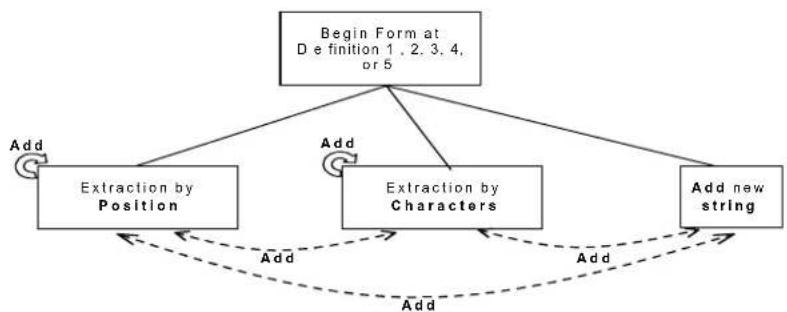
flowchart
graph TD
    A["Begin Form at D e finition 1, 2, 3, 4, or 5"] --> B["Add"]
    A --> C["Add"]
    C --> D["Extraction by Position"]
    C --> E["Add"]
    E --> F["Extraction by Characters"]
    E --> G["Add"]
    G --> H["Add new string"]
    H --> I["Add"]
    I --> J["Add"]
    J --> K["Add"]
    K --> L["Add"]
    L --> M["Add"]
    M --> N["Add"]
    N --> O["Add"]
    O --> P["Add"]
    P --> Q["Add"]
    Q --> R["Add"]
    R --> S["Add"]
    S --> T["Add"]
    T --> U["Add"]
    U --> V["Add"]
    V --> W["Add"]
    W --> X["Add"]
    X --> Y["Add"]
    Y --> Z["Add"]
    Z --> A
Example Method 1 Extracting Information from Barcode
Decoded code:
Formatting procedure : Add new string + Extract field by position + Add new string + Extract field by character + Add new string
Add New String
String
character(s) End String Add

Field Extraction by Position
Field
Starting Position
Field Ending Position
End Selection Add

+1+

+3+


Add New String
String character(s) End String Add

+32+31+


- Field Extraction by Character
End Selection Including Starting and Ending Characters Add
Field
Starting
Characters
Field Ending Character

+4F + 47 +

+72+


Add New String
String
character(s) End String End Format

+32+31+


Output message: <21DAT21OGICpr21>
FIELD EXTRACTION BY CHARACTER
a) Define Field Starting Character(s)
Field Starting Character(s)

Read the Hex value from the Hex/Numeric table identifying the starting character(s) of the field to be extracted. Valid values are in the range 00-7F.
b) Define Field Ending Character(s)
Field Ending Character(s)

Read the Hex value from the Hex/Numeric table identifying the ending character(s) of the field to be extracted. Valid values are in the range 00-7F.
c) Field Delimiter Selection
Include Start/End Characters

OR
Discard Start/End Characters

d) EITHER Add Field or String
Add

- To add other fields selected by characters read the code and repeat this procedure from stepa for each field to be selected;
- To add a new string of characters read the code and follow the procedure described on page 141.
- To add the procedure selecting new fields by position read the code and follow the description given on page 140.
OR End Format Definition
End Format Definition

Read the code to end the format definition.
FIELD EXTRACTION BY POSITION
a) Define Field Starting Position
Field Starting Position

Read a number corresponding to the field starting position.
b) Define Field Ending Position
Field Ending Position Last Position

Read a number corresponding to the field ending position.
OR

Read this code to set the field ending position to the last position of the code:
c) End Field Selection
End Selection

Read the code to end the field selection.
d) EITHER Add Field or String
Add

- To add other fields selected by position read the code and repeat this procedure from stepa for each field to be selected;
- To add a new string of characters read the code and follow the procedure described on page 141.
- To add the procedure selecting new fields by characters read the code and follow the description given on page 139.
OR End Format Definition
End Format Definition

Read the code to end the format definition.
ADD NEW STRING
a) Define New String
String Character(s)

Read the Hex value from the Hex/Numeric table identifying the character(s). Valid values are in the range 00-7F.
b) End String
End String

Read the code to end the string defined in step a.
c) EITHER Add Procedure
Add

• To add the procedure extracting fields by characters, follow the steps given on page 139;
- To add the procedure extracting fields by position follow the steps given on page 140.
OR
End Format Definition
End Format Definition

Read the code to end the format definition.
Method 2 - Manipulating the Barcode Data
Method 2 allows modifying the barcode data by means of one of the following procedures:
- String insertion;
- String deletion;
- String substitution;
- Field deletion.
Once the data has been modified, it is sent to the host computer as data of the output message.
Unlike Method 1 this method does not allow associating different procedures together. This means that each format definition corresponds to a single procedure. Despite this, it possible to add a new string of characters to the beginning or ending part of the formatted barcode.
The only limit is determined by the size of the internal reserved memory used to define the format.
STRING INSERTION
To complete this procedure proceed as follows:
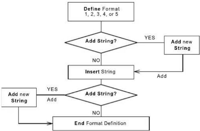
flowchart
graph TD
    A["Define Format 1, 2, 3, 4, or 5"] --> B{Add String?}
    B -->|YES| C["Add new String"]
    B -->|NO| D["Insert String"]
    C --> E["Add new String"]
    D --> F{Add String?}
    F -->|YES| G["Add new String"]
    F -->|NO| H["End Format Definition"]
    G --> H
Example:
Decoded code:
Formatting procedure: Add new string + Insert String
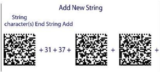
text_image
Add New String String character(s) End String Add + 31 + 37 + + + +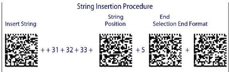
text_image
String Insertion Procedure Insert String String Position End Selection End Format ++ 31 + 32 + 33 + + 5 +Output message: <17DATA123LOGICproduct>
String Insertion Procedure
a) Insert String
Insert String

Read the Hex value from the Hex/Numeric table identifying the characters to be inserted. Valid values are in the range 00-7F.
b) Define String Position
String Position

Read a number corresponding to the string position within the barcode.
c) End Selection
End Selection

Read the code to end the field selection.
d) EITHER Add String
Add

To add a new string of characters read the code and follow the procedure described on page 150.
OR End Format Definition
End Format Definition

Read the code to end the format definition.
STRING DELETION
To complete this procedure proceed as follows:

flowchart
graph TD
    A["Define Format 1, 2, 3, 4, or 5"] --> B{Add String?}
    B -->|YES| C["Add new String"]
    B -->|NO| D["Delete String"]
    C --> E["End Format Definition"]
    D -->|Delete| F["Add new String"]
    F --> G{Add String?}
    G -->|YES| H["Add new String"]
    G -->|NO| I["End Format Definition"]
Example:
Decoded code:
Formatting procedure: Delete First String + Delete Second String + Add New String.

text_image
String Deletion Procedure Delete String Loop + 4C +4F + End Selection Add + 6F +64 + +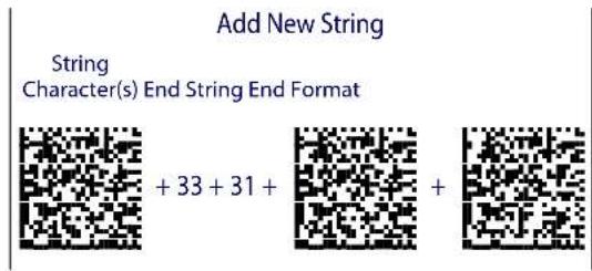
text_image
Add New String String Character(s) End String End Format + 33 + 31 + + +Output message:
String Deletion Procedure
a) Delete String
Delete

Read the Hex value from the Hex/Numeric table identifying the string character(s) to be deleted. Valid values are in the range 00-7F.
b) (optional) Select Other Strings to be Deleted
Loop

Read the code above and repeat the procedure from step a.
c) End Selection
End Selection

Read the code to end the selection.
d) EITHER Add String
Add

To add a new string of characters read the code and follow the procedure described on page 150.
OR End Format Definition
End Format Definition

Read the code to end the format definition.
STRING SUBSTITUTION
To complete this procedure proceed as follows:

flowchart
graph TD
    A["Define Format 1, 2, 3, 4, or 5"] --> B{Add String?}
    B -->|YES| C["Add new String"]
    B -->|NO| D["Substitute String"]
    C --> E["Add"]
    D --> F{Add String?}
    F -->|YES| G["Add new String"]
    F -->|NO| H["End Format Definition"]
    G --> H
Example
Decoded code:
Formatting procedure: Add new string + String substitution + Add new string.
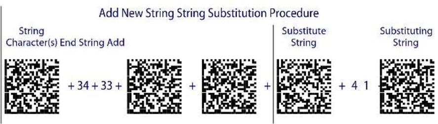
text_image
Add New String String Substitution Procedure String Character(s) End String Add + 34 + 33 + Substitute String Substituting String + 4 1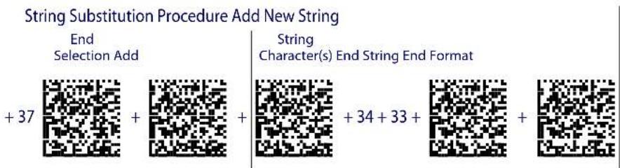
text_image
String Substitution Procedure Add New String End Selection Add + 37 + + String Character(s) End String End Format + 34 + 33 + +Output message: <43D7T7LOGICproduct43>
String Substitution Procedure
a) Define String to be Substituted
Substitute String

Read the Hex value from the Hex/Numeric table identifying the characters of the string to be substituted. Valid values are in the range 00-7F.
b) Define Substituting String
Substituting String

Read the Hex value from the Hex/Numeric table identifying the characters of the substituting string. Valid values are in the range 00-7F.
c) End Selection
End Selection

Read the code to end the selection.
d) EITHER Add String
Add

To add a new string of characters read the code and follow the procedure described on page 150.
OR End Format Definition
End Format Definition

Read the code to end the format definition.
FIELD DELETION
To complete this procedure proceed as follows:

flowchart
graph TD
    A["Define Format\n1, 2, 3, 4, or 5"] --> B{Add String?}
    B -->|YES| C["Add new String"]
    B -->|NO| D["Delete Field"]
    C --> D
    D --> E{Delete}
    E -->|Yes| F["Add new String"]
    E -->|No| G["End Format Definition"]
    F --> G
Example
Decoded code:
Formatting procedure: Delete First Field + Delete Second Field + Add New String.
Field Deletion Procedure
Delete 1

^st Field Starting Character

1^st Field Ending Character
+41+

+4C + 4F +
Field Deletion Procedure
End
Selection Loop


2nd Field Starting Character

+70+72+
2 ^nd Field
Ending
Character

Field Deletion Procedure Add New String
+75+
End
Selection Add


String
Character(s) End String End Format

+35+31+


Output message:
Field Deletion Procedure
a) Delete Field
Delete

Read the code to enable the command deleting the field.
b) Define Field Starting Character
Field Starting Character

Read the Hex value from the Hex/Numeric table identifying the starting characters. Valid values are in the range 00-7F.
c) Define Field Ending Character
Field Ending Character

Read the Hex value from the Hex/Numeric table identifying the ending character/s. Valid values are in the range 00-7F.
d) End Field Selection
End Selection

Read the code to end the field selection.
e) (optional) Select Other Fields to be Deleted
Loop

Read the following code and repeat the procedure from step b for each field to be deleted.
f) EITHER Add String
Add

To add a new string of characters read the code and follow the procedure described on page 150.
OR End Format Definition
End Format Definition

Read the code to end the format definition.
ADD NEW STRING
a) Define New String
String Character

Read the Hex value from the Hex/Numeric table identifying the starting characters. Valid values are in the range 00-7F.
b) End String and Define Procedure
End String Plus Procedure

Read the code to end the string selection and continue defining a new procedure belonging to Method 1.
OR
End String and Format
End String & Format

Read the code to end the string and the format definition.
Match Conditions
By setting one or more of the following conditions it is possible to select the codes to be formatted. Follow the given steps to define the desired condition.
MATCH WITH PREDEFINED SUBSTRING
Define Matching Substring
Match with Substring

Read the above code and:
- read a number in the range 1-5 corresponding to the desired format number;
- set the number of characters defining the matching string in the range 00-10;
- read the corresponding character as Hex value from the Hex/Numeric table identifying the substring character/s. Valid values are in the range 00-7F.
(optional) Define Substring Position
Matching Substring Position

Read the above code and:
- read a number in the range 1-5 corresponding to the desired format number;
- read the number corresponding to the substring position in the range 0-255;
AND/OR
MATCH CODE LENGTH
Define Code Length
Match Code Length

Read the above code and:
- read a number in the range 1-5 corresponding to the desired format number;
- read the number in the range 0-255;
AND/OR
MATCH SYMBOLOGY
Define Code Symbology
Match Symbology

Read the above code and:
- read a number in the range 1-5 corresponding to the desired format number;
- set the number of the matching code symbologies in the range 0-4;
- select the Datalogic Standard Code Identifier from the Code Identifier Table in Appendix D.
Format Enable/Disable
Format 1 Format 2

0 = d i s a b l e d 0 = d i s a b l e d
1 = enabled 1 = enabled

Format 3 Format 4

0 = d i s a b l e d 0 = d i s a b l e d
1 = enabled 1 = enabled

Format 5 Disable All Formats

0 = d i s a b l e d
1 = e n a b l e d

Mismatch Result
The result of each format may be set in case the match conditions previously selected are not satisfied.
Once the desired formats have been enabled and a code has been read, the results corresponding to each format will be concatenated together and transmitted in the output message. For this reason, it is strongly advised to set the mismatch result for each format.
Example
Decoded Code:
Format definition:
| Format | Enable/Disable | Match Condition | Function | Mismatch Result |
| Format 1 Enabled | Code having a length of 16 characters | Select field from position1 to position3 | No string | |
| Format 2 Disabled // / | ||||
| Format 3 Enabled | Code having a length of 25 characters | Substitute string "ab" with string "12" | Unformatted read code | |
| Format 4 Enabled | Code having the sub-string "AT" in position 2 | Insert string "789" in position 7 | Unformatted read code | |
| Format 5 Enabled | Code belonging to the PDF417 symbology | Delete string "DA" and "pr" | Unformatted read code |
Output message:
Format 1 Format 3
Format 4
Format 6
Define Mismatch Result
Mismatch Result

Read the code at left and:
- read a number in the range 1-5 corresponding to the desired format number;
- 0 = empty string as output 1 = unformatted read code as output.
NOTES
RS-232 Parameters
Handshaking
Hardware handshaking: (RTS/CTS)
The RTS line is activated by the decoder before transmitting a character. Transmission is possible only if the CTS line (controlled by the Host) is active.
Figure 23. RTS/CTS handshaking

text_image
Signals at EIA levels RTS TX Transmitted data Transmitted data CTS Host busySoftware handshaking: (XON/XOFF)
During transmission, if the Host sends the XOFF character (13 Hex), the decoder interrupts the transmission with a maximum delay of one character and only resumes when the XON character (11 Hex) is received.
Figure 24. XON/XOFF handshaking

text_image
TX Transmitted data Transmitted da RX FF Host busy XON XO Host readyACK/NACK Protocol
PowerScan ^® M8500 Readers
The transmission protocol takes place between reader, cradle and Host. The reader passes its data (code read) to the cradle, which sends it to the Host. The management of responses (from Host or cradle) depends on the Transmission Mode parameter, see page 171.
In the following descriptions the completed transmission is indicated by the Beeper Control for Radio Response parameter with its default setting to Normal, see page 171.
When ACK/NACK is disabled (in One-Way tx mode), there is no control from cradle to Host transmission, the reader responds with the good reception tone.
Figure 25. ACK/NACK disabled
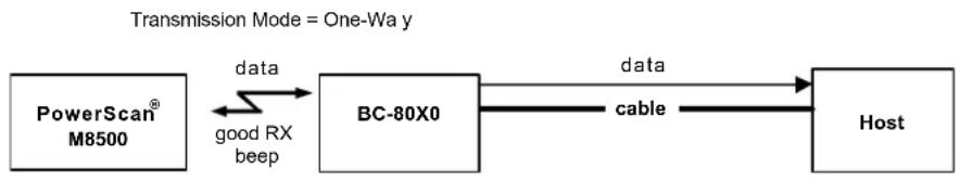
flowchart
graph LR
    A["PowerScan® M8500"] -->|data| B["BC-80X0"]
    B -->|data| C["Host"]
    B -->|cable| C
    A <-->|good RX beep| B
Figure 26. ACK/NACK enabled
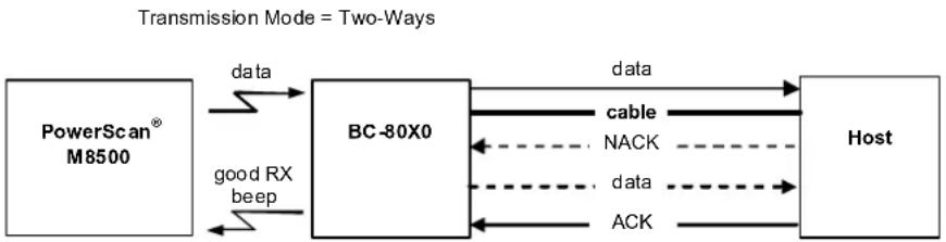
flowchart
graph LR
    A["PowerScan® M8500"] -->|data| B["BC-80X0"]
    B -->|data| C["Host"]
    B -->|good RX beep| A
    B -->|NACK| B
    B -->|data| B
    B -->|ACK| B
    style A fill:#f9f,stroke:#333
    style B fill:#ccf,stroke:#333
    style C fill:#cfc,stroke:#333
When ACK/NACK is enabled (in Two-Way tx mode), the Host sends an ACK character (06 HEX) in the case of good reception or the NACK character (15 HEX) requesting re-transmission, in the case of bad reception. Only after the ACK character is received by the BC-80X0 does the reader respond with the good reception tone.
If the BC-80X0 does not receive an ACK or NACK, transmission is ended after the RX Timeout, see page 157. See also Radio Protocol Timeout, page 170.
When ACK/NACK protocol is enabled, FIFO must be disabled manually, see below.
FIFO
PowerScan ^® M8500 Readers
If enabled, the BC-80X0 collects all messages sent by PowerScan ^® M8500 and sends them in order of acquisition to the connected Host.
If disabled, PowerScan ^® M8500 blocks message transmission until the BC-80X0 has completed transmission towards the Host.
RX Timeout
When the RS-232 interface is selected, the Host can be used to configure the device by sending it command strings (see Appendix B, Host Configuration Strings).
This parameter can be used to automatically end data reception from the Host after the specified period of time.
If no character is received from the Host, after the timeout expires, any incomplete string (any string not terminated by
Pen Parameters
Minimum Output Pulse
This parameter sets the duration of the output pulse corresponding to the narrowest element in the barcode. In this way the code resolution is controlled by the signal sent to the decoder, independently of the physical resolution of the code read.
The shortest pulse (200 s) corresponds to a high-resolution code emulation and therefore a shorter transfer speed to the decoder (for decoders able to work on high resolution codes). Likewise, longer pulses correspond to low-resolution code emulation and therefore a longer transfer time to the decoder.
Conversion to Code 39 and Code 128
PowerScan ^® M8500 Series Readers
When using these readers it is possible to choose between converting the decoded codes into either Code 39 format or Code 128 format. It is not possible to disable conversion.
Overflow
This parameter generates a white space before the first bar and after the last bar of the code. The selections are as follows:
narrow=space 10 times the minimum output pulse.
medium=space 20 times the minimum output pulse.
wide = space 30 times the minimum output pulse.
Output and Idle Levels
The following state diagrams describe the different output and idle level combinations for Pen emulation:
Figure 27. Output and Idle Levels

text_image
OUTPUT: Normal idle bar IDLE: Normal space barcode output OUTPUT: Normal idle space bar IDLE: Inverted space barcode output OUTPUT: Inverted idle space bar IDLE: Normal space barcode output OUTPUT: Inverted idle space bar IDLE: Inverted space barcode output OUTPUT: Normal black white OUTPUT: Normal black white OUTPUT: Inverted white IDLE: Normal black OUTPUT: Inverted white IDLE: Inverted blackInter-Block Delay
For the PEN Emulation interface, data are sent to the Host in fixed size blocks of 20 characters each. The inter-block delay parameter allows setting a delay between each block sent to the Host.
Network Parameters
Slave Address Range First/Last
These parameters define the valid addresses for the Slave cradles on the network. Valid values are in the range 0 to 1999. However, the maximum number of cradles in a single network is 16, (including the Master if present). All cradles in the system must have different addresses.
To reduce system boot time, it is recommended to number the Slaves consecutively, while it is not necessary that the Master cradle address is contained in the range. The network addresses correspond to the radio addresses, see "BC-8060 STAR-System™ Network Setup" on page 45.
At system power-up, the Master searches for and initializes all the Slaves found in the valid address range. During this phase the yellow LED on the Master cradle blinks. The time to complete the start up procedure varies depending on the complexity of the network but is typically between a few seconds to a few minutes. Start up cannot be interrupted. At the end of this procedure the system will be operative and can collect data from all devices.

CAUTION
All Slaves must be powered up either before or together with the Master. Slaves successively powered will not be recognized by the system even if their address is in the specified range.
Network Warning Message
The Master cradle can transmit warning messages to the Host regarding some network errors.
/*Slave xxxx not responding*/: when the Master can no longer communicate with the specified Slave previously identified at start up.
/*Frame out of sequence for terminal xxxx*/: if a reader is sending data packets out of sequence. This can happen if there are transmission problems on the network (either connection or communication), or if the reader has correctly transmitted data to a device not on the network (reader configuration error).
The message is sent in the following format:
"Message" CR LF
Reception Warning Message
The Master cradle can transmit warning messages to the Host regarding wrong reception of data. Example:
/*Two-Ways Out of Sequence! (....)*/
This message is transmitted to the Host by the Master cradle when the Master cradle receives a closing string from the Host for a Two-way tx communication, but this was either not open or already closed, therefore the data will be lost. See page 171.
Master Header/Terminator Selection
In addition to the standard header/terminator selection, the Master cradle can add its own header/terminator to the entire message sent to the Host.
In the STAR-System ^TM network headers and terminators for all RF Devices are disabled by default.
The Master header and terminator default values are as follows depending on the interface selection towards the Host:
• RS-232: no header, terminator CR-LF
- WEDGE: no header, terminator ENTER
See "Header/Terminator Selection" on page 160 and "Define Special Key Sequence" on page 161.
Data Format
For an overview of Message Formatting see Chapter 6.
Header/Terminator Selection
The header/terminator selection is not effected by the reading of the restore default code. In fact, header and terminator default values depend on the interface selection:
• RS-232: no header, terminator CR-LF
- WEDGE: no header, terminator ENTER
These default values are always restored through the reading of RS-232 or WEDGE interface selection code, see "Interface Selection" on page 47.
For the WEDGE interface, the following extended keyboard values can also be configured:
| EXTENDED KEYBOARD TO HEX CONVERSION TABLE | ||||
| IBM AT IBM 3153 APPLE ADB | IBM XT | IBM 31xx, 32xx, 34xx, 37xx | Wyse Digital | |
| HEX KEY | KEY KEY KEY | |||
| 83 ENTER ENTER FIELD EXIT RETURN | ||||
| 84 TAB TAB TAB | ||||
| 85 | F1 | F1 | F1 | F1 |
| 86 | F2 | F2 | F2 | F2 |
| 87 | F3 | F3 | F3 | F3 |
| 88 | F4 | F4 | F4 | F4 |
| 89 | F5 | F5 | F5 | F5 |
| 8A | F6 | F6 | F6 | F6 |
| 8B | F7 | F7 | F7 | F7 |
| 8C | F8 | F8 | F8 | F8 |
| 8D | F9 | F9 | F9 | F9 |
| 8E | F10 | F10 | F10 | F10 |
| 8F | F11 | ESC | F11 | F11 |
| 90 | F12 | BACKSPACE | F12 | F12 |
| 91 | HOME | HOME | ENTER | F13 |
| 92 | END | END | RESET | F14 |
| 93 | PG UP | PG UP | INSERT | F15 |
| 94 | PG DOWN | PG DOWN | DELETE | F16 |
| 95 | - | FIELD - | UP | |
| 96 | - | - | FIELD + | DOWN |
| 97 | - | - | ENTER (Paddle) | LEFT |
| 98 | * | RIGHT | ||
| 99 ESC | ESC | ESC | ||
| 9A | CTRL (Right) | CTRL (Right) | CTRL (Right) | |
| 9B | Euro | Space | Space | Space |
For all devices using IBM AT (compatible) Wedge or USB-KBD interfaces, all values from 9C to FE send the relative simulated keypress when available or else the relative ALT-Mode sequence. See the Hex to Character Conversion Table in Appendix F.
For all devices using other Wedge interfaces, all values from 9C to FE send the Space character.
Define Special Key Sequence
The Special Key(s) for Wedge IBM AT-PS/2 and USB-KBD interface users can be associated with a sequence of keyboard keys that otherwise could not be selected, i.e. ALT + F6, SHIFT + F1. These Special Keys can be used for:
- Headers/Terminators
- Character Replacement
- F i e l d A d j u s t m e n t
- C u s t o m C o d e I D
- Advanced Formatting – Define Field
- Advanced Formatting – Additional Fixed Field
Follow the procedure to define the desired Special Key sequence:
- Read the Enter Configuration code above and select the Special Key to define (one at a time):
Define Special Key 1 Define Special Key 2


Define Special Key 3 Define Special Key 4


Define Special Key 5


- Read only one code to be associated with the special key sequence:
SHIFT CTRL

OR

OR
ALT CTRL + SHIFT

OR

OR
ALT + SHIFT CTRL + ALT

OR

- Select the character to be associated with the Special Key sequence by reading the codes corresponding to the 3 character values from Appendix F.
Then, read the Exit and Save Configuration code above to complete the Special Key sequence.
The character values having the ^S and ^A symbols require SHIFT or ALT keys or key combinations in step 2, in particular:
s = the character is obtained in combination with SHIFT
A = the character is obtained in combination with ALT
The following character values change according to the keyboard nationality.
| CHAR\KEYB | ITA | USA | FR | BE | DE | UK | ES | SW | JP |
| !016 | S | 016^S | 04A 03E | 016 | S | 016^S | 016^S | 016^S | 016^S |
| "01E | S | 052^S | 026 026 | 01E | S | 01E^S | 01E^S | 01E^S | 01E^S |
| #052 | A | 026^S | 026^A | 026^A | 05D 05D | 026 | A | 026^S | 026^S |
| 025 | S | 025^S | 05B 05B | 025 | S | 025^S | 025^S | 025^A | 025^S |
| %02E | S | 02E^S | 052^S | 052^S | 02E^S | 02E^S | 02E^S | 02E^S | 02E^S |
| &036 | S | 03D^S | 016 016 | 036 | S | 03D^S | 036^S | 036^S | 036^S |
| ' | 04E 052 | 025 | 025 05D | S | 052 | 04E 05D | 03D | S | |
| ( | 03E^S | 046^S | 02E 02E | 03E | S | 046^S | 03E^S | 03E^S | 03E^S |
| )046 | S | 045^S | 04E 04E | 046 | S | 045^S | 046^S | 046^S | 046^S |
| * | 05B^S | 03E^S | 05D | 05B^S | 05B | 03E^S | 05B^S | 05D^S | 052^S |
| + | 05B 055 | S | 055^S | 04A^S | 05B 055 | S | 05B 04E | 04C | S |
| , | 041 | 041 | 03A | 03A | 041 | 041 | 041 | 041 | 041 |
| - | 04A | 04E | 036 | 055 | 04A | 04E | 04A | 04A | 04E |
| . | 049 | 049 | 041^S | 041^S | 049 049 | 049 | 049 | 049 | |
| / | 03D^S | 04A 049 | S | 049^S | 03D^S | 04A | 03D^S | 03D^S | 04A |
| 0 | 045 | 045 | 045^S | 045^S | 045 045 | 045 | 045 | 045 | |
| 1 | 016 | 016 | 016^S | 016^S | 016 016 | 016 | 016 | 016 | |
| 2 | 01E | 01E 01E | S | 01E^S | 01E 01E | 01E | 01E | 01E | |
| 3 | 026 | 026 | 026^S | 026^S | 026 026 | 026 | 026 | 026 | |
| 4 | 025 | 025 | 025^S | 025^S | 025 025 | 025 | 025 | 025 | |
| 5 | 02E | 02E 02E | S | 02E^S | 02E 02E | 02E | 02E | 02E | |
| 6 | 036 | 036 | 036^S | 036^S | 036 036 | 036 | 036 | 036 | |
| 7 | 03D | 03D | 03D^S | 03D^S | 03D 03D | 03D 03D | 03D | ||
| 8 | 03E | 03E 03E | S | 03E^S | 03E 03E | 03E | 03E | 03E | |
| 9 | 046 | 046 | 046^S | 046^S | 046 046 | 046 | 046 | 046 | |
| :049 | S | 04C^S | 049 049 | 049 | S | 04C^S | 049^S | 049^S | 052 |
| ;041 | S | 04C | 041 041 | 041 | S | 04C 041 | S | 041^S | 04C |
| < | 061 041 | S | 061 061 | 061 | 041 | S | 061 061 | 041 | S |
| =045 | S | 055 055 | 04A 045 | S | 055 | 045^S | 045^S | 04E^S | |
| >061 | S | 049^S | 061^S | 061^S | 061^S | 049^S | 061^S | 061^S | 049^S |
| ? | 04E | 04A^S | 03A^S | 03A^S | 04E^S | 04A^S | 04E^S | 04E^S | 04A^S |
| @04C | A | 01E^S | 045^A | 01E^A | 015^A | 052^S | 01E^A | 01E^A | 054 |
| [054 | A | 054 | 02E^A | 054^A | 052^S | 054 | 054^A | 03E^A | 05B |
| \ | 00E | 05D | 03E^A | 061^A | 04C^S | 061 00E | A | 04E^A | 051 |
| ] | 05B^A | 05B | 04E^A | 05B^A | 054^S | 05B | 05B^A | 046^A | 05D |
| ^055 | S | 036^S | 046^A | 054 | 00E 036 | S | 054^S | 05B^S | 055 |
| _04A | S | 04E^S | 03E | 055 04A | S | 04E^S | 04A^S | 04A^S | 051^S |
| '(accent) | - | 00E | 03D^A | 05D^A | 055^S | 00E | 054 | 055^S | 054^S |
| a | 01C | 01C | 015 | 015 | 01C | 01C | 01C | 01C | 01C |
| b | 032 | 032 | 032 | 032 | 032 | 032 | 032 | 032 | 032 |
| c | 021 | 021 | 021 | 021 | 021 | 021 | 021 | 021 | 021 |
| d | 023 | 023 | 023 | 023 | 023 | 023 | 023 | 023 | 023 |
| e | 024 | 024 | 024 | 024 | 024 | 024 | 024 | 024 | 024 |
| f | 02B | 02B | 02B | 02B | 02B | 02B | 02B | 02B | 02B |
| g | 034 | 034 | 034 | 034 | 034 | 034 | 034 | 034 | 034 |
| h | 033 | 033 | 033 | 033 | 033 | 033 | 033 | 033 | 033 |
| i | 043 | 043 | 043 | 043 | 043 | 043 | 043 | 043 | 043 |
| j | 03B | 03B | 03B | 03B | 03B | 03B | 03B | 03B | 03B |
| k | 042 | 042 | 042 | 042 | 042 | 042 | 042 | 042 | 042 |
| l | 04B | 04B | 04B | 04B | 04B | 04B | 04B | 04B | 04B |
| m | 03A | 03A | 04C | 04C | 03A | 03A | 03A | 03A | 03A |
| n | 031 | 031 | 031 | 031 | 031 | 031 | 031 | 031 | 031 |
| o | 044 | 044 | 044 | 044 | 044 | 044 | 044 | 044 | 044 |
| p | 04D | 04D | 04D | 04D | 04D | 04D | 04D | 04D | 04D |
| q | 015 | 015 | 01C | 01C | 015 | 015 | 015 | 015 | 015 |
| r 02D | 02D 02D 02D | 02D 02D | 02D 02D 02D | ||||||
| s 01B | 01B 01B 01B | 01B 01B | 01B 01B 01B | ||||||
| t 02C | 02C 02C 02C | 02C 02C | 02C 02C 02C | ||||||
| u 03C | 03C 03C 03C | 03C 03C | 03C 03C 03C | ||||||
| v 02A | 02A 02A 02A | 02A 02A | 02A 02A 02A | ||||||
| w 01D | 01D 01A 01A | 01D 01D | 01D 01D 01D | ||||||
| x 022 | 022 022 022 | 022 | 022 022 | 022 022 | |||||
| y | 035 | 035 | 035 | 035 | 01A | 035 | 035 | 035 | 035 |
| z 01A | 01A 01D 01D | 035 | 01A 01A | 01A 01A | |||||
| - | 054^S | 025^A | 046^A | 052 054 | S | 052^A | 03D^A | 05B^S | |
| | | 00E^S | 05D^S | 036^A | 016^A | 04C | 061^S | 016^A | 061^A | 06A^S |
| - | 05B^S | 055^A | 045^A | 054 | 05B^S | 05D^A | 045^A | 05D^S | |
| ~ | - | 00E^S | 01E^A | 04A^A | 04E | 05D^S | - | 05B^A | 055^S$ |

To use upper case letters, it is necessary to read one of the SHIFT commands from step 2 before the value corresponding to the lower case letters.
The following key values are common to all the keyboard nationalities.
| KEYB KEY | ITA | USA | FR | BE | DE | UK | ES | SW | JP |
| ENTER 05A 05A 05A | 05A 05A 05A | 05A 05A 05A | 05A 05A 05A | 05A | |||||
| TAB | 00D | 00D | 00D | 00D | 00D | 00D | 00D | 00D | 00D |
| F1 | 005 | 005 | 005 | 005 | 005 | 005 | 005 | 005 | 005 |
| F2 | 006 | 006 | 006 | 006 | 006 | 006 | 006 | 006 | 006 |
| F3 | 004 | 004 | 004 | 004 | 004 | 004 | 004 | 004 | 004 |
| F4 | 00C | 00C | 00C | 00C | 00C | 00C | 00C | 00C | 00C |
| F5 | 003 | 003 | 003 | 003 | 003 | 003 | 003 | 003 | 003 |
| F6 | 00B | 00B | 00B | 00B | 00B | 00B | 00B | 00B | 00B |
| F7 | 083 | 083 | 083 | 083 | 083 | 083 | 083 | 083 | 083 |
| F8 | 00A | 00A | 00A | 00A | 00A | 00A | 00A | 00A | 00A |
| F9 | 001 | 001 | 001 | 001 | 001 | 001 | 001 | 001 | 001 |
| F10 | 009 | 009 | 009 | 009 | 009 | 009 | 009 | 009 | 009 |
| F11 | 078 | 078 | 078 | 078 | 078 | 078 | 078 | 078 | 078 |
| F12 | 007 | 007 | 007 | 007 | 007 | 007 | 007 | 007 | 007 |
| Home | 26C | 26C | 26C | 26C | 26C | 26C | 26C | 26C | 26C |
| End | 269 | 269 | 269 | 269 | 269 | 269 | 269 | 269 | 269 |
| PG UP | 27D | 27D | 27D | 27D | 27D | 27D | 27D | 27D | 27D |
| PG down | 27A 27A | 27A 27A | 27A 27A 27A | 27A 27A 27A | |||||
| Up arrow | 275 | 275 | 275 | 275 | 275 | 275 | 275 | 275 | 275 |
| Down arrow | 272 | 272 | 272 | 272 | 272 | 272 | 272 | 272 | 272 |
| Left arrow | 26B 26B | 26B 26B | 26B 26B 26B | 26B 26B 26B | |||||
| Right arrow | 274 | 274 | 274 | 274 | 274 | 274 | 274 | 274 | 274 |
| Esc | 076 | 076 | 076 | 076 | 076 | 076 | 076 | 076 | 076 |
| Ctrl right | 214 | 214 | 214 | 214 | 214 | 214 | 214 | 214 | 214 |
| € | 02E^A | 02E^A | 024^A | 024^A | 024^A | 025^A | 02E^A | 02E^A | - |
| SPACE | 029 | 029 | 029 | 029 | 029 | 029 |

If Caps Lock Auto-Recognition is disabled, it is necessary to verify that the keyboard caps lock status matches the reader one.
EXAMPLES
- Defining Special Key Sequences -
- The following example allows defining Special Key 1 as SHIFT + F5:
enter
configuration define Special Key 1 SHIFT
Read + + +


codes from Appendix F
corresponding to the character value for F5
exit & save configuration
+
003
+

- The following example allows defining Special Key 2 as CTRL + S (upper case):
enter
configuration define Special Key 2 CTRL + SHIFT
Read + + +


codes from Appendix F
corresponding to the character value for s (lower case)
exit & save configuration
+
01B
+

- The following example allows defining Special Key 3 as Alt + F6:
enter
configuration define Special Key 3 ALT
Read + + +


codes from Appendix F
corresponding to the character value for F6
exit & save configuration
+
00B
+

- The following example allows defining Special Key 4 as Alt + Shift + F1:
enter
configuration define Special Key 4 ALT + SHIFT
Read + + +


codes from Appendix F
corresponding to the character value for F1
exit & save configuration
+
005
+

- Integrating Special Keys in Headers/Terminators -
- The following example allows setting Special Key 1 (defined in example 1 above) as terminator:
enter configuration

one character
terminator special key 1


exit & save configuration

- The following example allows setting Special Ke y 2 (defined in example 2 above) as header:
enter
configuration one character header special key 2


exit & save configuration

- tHe following example allows setting Special Key 3 (defined in example 3 above) as header:
enter
configuration one character header special key 3


exit & save configuration

- The following example allows setting Special Key 4 (defined in example 4 above) and ENTER character as terminators:
enter
configuration

two character
terminator special key 4


ASCII characters corresponding to the HEX value for character ENTER
83
exit & save configuration

+
Address Stamping
It is possible to include the reader address in the message sent to the host. The Reader Address Stamping and the Cradle Address Stamping parameters consist of a 4-digit number in the range 0000 to 1999.
For message output format, refer to "Message Formatting" starting on page 175
Address Delimiter
The Address Delimiter allows a character to be included to separate the reader Address stamping field from the next field in the message. Any character can be included in the hexadecimal range from 00 to FE.
For message output format, refer to "Message Formatting" starting on page 175.
Time Stamping Format
The Time Stamping parameter sets the format for hour and date information. It consists of 1 or 2 groups of numbers, each one made up of 6 decimal digits.
For example, setting the Hour/Minutes/Seconds/Month/Day/Year format, the information 17:03:16 on June 12, 2009 will be formatted as 170316061209.
Time Stamping Delimiter
The Time Stamping Delimiter allows a character to be included to separate the Time Stamping field from the next field in the message. Any character can be included in the hexadecimal range from 00 to FE.
Reading Parameters
Trigger Signal
This mode determines how the reading phase is controlled when the hardware trigger operating mode is selected:
- trigger active level: the reader goes ON when the trigger is pressed and goes OFF when it is released
- trigger active pulse: the reader goes ON at the first trigger press and goes OFF only at a second press
Reads per Cycle
In general, a reading cycle corresponds to the ON + OFF times of a device.
The resulting effects of this parameter on code reading depend on other related configuration conditions. Here are the definitions of ON and OFF times.
- For readers using the software trigger parameter (FL ASH MODE), a reading cycle corresponds to the flash on + flash off times. Code reading takes place during the flash on time.
-
For readers using the bar dware trigger parameter, a reading cycle corresponds to a trigger press (ON) + one of the following OFF events:
-
trigger release (for trigger active level)
- a second trigger press (for trigger active pulse)
When one read per cycle is selected, the device decodes only one code during the ON period and immediately turns the reader OFF. It is only possible to read another code when the next ON time occurs.
In multiple reads per cycle, the ON period is extended so that the device can continue decoding codes until an OFF event occurs. For software trigger mode, the flash on period is immediately reset after each read and therefore extended. If another code is decoded before the reset flash on period expires, it is again reset and the effect is that the device remains ON, decoding codes until the flash on or timeout period expires.
The Safety Time parameter should be used in this case to avoid unwanted multiple reading of the same code, see below.
Safety Time
Safety time prevents the device from immediately decoding the same code more than once. Same code consecutive reading can be disabled requiring the reader to be removed from the code (no decoding) for at least 400 ms, or a timeout can be set up to 9.9 seconds before the decoder will accept the same code. Reading is immediate if the code changes.
The safety time parameter is not applicable when reading stacked codes or when setting one read per cycle in hardware trigger operating mode, since these settings require voluntary action by the user.
Configuration Editing Commands
The following commands carry out their specific function and do not require reading the Enter or Exit and Save Configuration codes.
Command Description

Restore PowerScan ^® M8500 reader default configuration.

Transmit the PowerScan ^® M8500 reader Software release.

Transmit the PowerScan ^® M8500 current configuration in ASCII format to Host.

Transmit the PowerScan ^® M8500 current data format configuration in ASCII format to Host.
Radio Parameters
Radio Protocol Timeout
This parameter sets the valid time to wait before transmission between the M8500 series reader and BC-80X0 cradle is considered failed.
This parameter should be set taking into consideration the radio traffic (number of readers in the same area).
If the RS-232 interface is used with ACK/NACK enabled, this parameter should be at least equal to the RX Timeout parameter for low traffic environments. It should be increased if there are many readers in the same area.
It can be set between 2 and 19 seconds.
Radio RX Timeout
When the scanner is used in a standalone layout (point-to-point or with multiple readers) it can be configured to receive “asynchronous” messages from the host at any time.
There are two modes which can enable the scanner to receive messages from the host:
- Enable “2 way” Communication Protocol – After the transmission of each barcode, the scanner waits for an acknowledgement from the host. ^1
A message can be sent by the host accompanying this acknowledgement, or in place of it, to display something on the screen or execute a command (such as sound a beep sequence, turn an LED on or off, etc.). If no acknowledgement or message is received from the host within a programmable timeout duration, the radio will be switched off and an “error transmission” beep will be sounded.
- I independent of the Selected Protocol – The scanner can be configured to keep the radio receiver “awake” for a defined period of time following each transmission. Any message coming from the host1 before expiration of the timeout is accepted. The parameter “Radio RX Timeout” is used for specifying how long the scanner have to wait for a message after receiving each code transmission.
In this mode, the radio can also be “awakened” by pressing the trigger. The scanner can receive a message only if it is linked to the Base (i.e. the scanner has been joined to the Base and has had at last one “valid” transmission after the last power-on). Setting the “Radio RX timeout” value to “00” specifies that the radio never goes into sleep mode (always awake the scanner can receive a message at any time). Choosing this setting will, of course, consume battery life more quickly.
Power-Off Timeout
If this command is enabled, after the desired timeout in hours, the PowerScan ^® batteries are disconnected and all power consumption ceases. To restore power, press the trigger once. The reader will now be ready to read codes.
Power-off does not affect configuration parameters.
Transmission Mode
This parameter determines whether the reader receives responses or messages from the Host or not. In One-Way tx mode, neither Host nor cradle responds to the reader. In Two-Way tx mode, the reader must receive a response from either the cradle or the Host.
The cradle responds (empty message) to the reader, only after good transmission to the Host, for the following conditions: ACK/NACK enabled (page 156); WEDGE or PEN interface. For these conditions, it is suggested to prolong the Radio Protocol Timeout (page 170).
Enabling Two-Way tx mode temporarily disables FIFO buffering (see page 156).
With ACK/NACK disabled, the Host responds to the reader (through the cradle) with an answer message (message to reader display or command to reader), see "Messages from Host to Reader" on page 175, and the following figure.
Figure 28. Transmission Mode = Two Ways
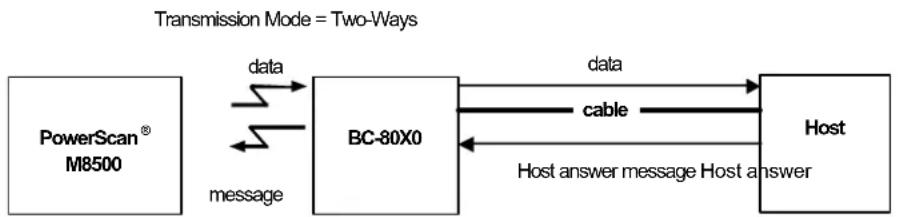
flowchart
graph LR
    A["PowerScan® M8500"] -->|message| B["BC-80X0"]
    B -->|data| C["Host"]
    B -->|cable| C
    C -->|Host answer message Host answer| B
    style A fill:#f9f,stroke:#333
    style B fill:#ccf,stroke:#333
    style C fill:#cff,stroke:#333
Beeper Control for Radio Response
For M8500 series readers, the data entry good read tone normally results in two beeps; the first indicates that the reader has decoded the code; the second indicates whether BC-80X0 has received the data.
This can be changed according to the following selections:
- Normal: both good decode and good r eceptions are signaled (two beeps).
- Only Good Decode: only the first beep indicating a good read is signaled.
- Only Good Reception: only the second beep indicating a good reception is signaled.
- Off: Neither good read nor good r eception beeps are signaled.
For all configurations, any transmission errors will always be signaled.
Single Store
When single store mode is enabled, if the PowerScan ^ M8500 fails to transmit a code to the cradle, it enters a special operating mode that prevents the user from reading barcodes.
When such operating mode is entered, the trigger no longer enables barcode reading but is used to retry transmission itself for the number of attempts selected in configuration. Once the transmission is successful the reader returns to the standard mode. If transmission is not successful after the number of configured attempts, the code is discarded.
Single store may be useful if you often read codes at the limit of the coverage area and there is a chance that code transmission can fail. In such case single store allows you to move to a more favorable position or location (i.e. closer to the cradle) and retry transmission without the necessity of re-reading the code since it is already stored in the reader.
Conversely, if single store is disabled, and the user wants to retry transmission, the code must be read again, and therefore the attempt must be made from basically the same location. If the user gives up, he does not know if the transaction was successful. (Actually the transmission could have been successful but the cradle may have been unable to acknowledge the message). There are applications in which there is no risk of transmission failure. In such cases it may be better to disable single store so that the user perceives a more consistent behavior of the trigger in that it always corresponds to code reading.
Batch Mode
This Operating Mode allows storing read codes in the internal reader memory. The stored codes are transmitted to the base station at a later time according to the type of batch mode selected.
Batch mode can be enabled either manually (normal batch mode) or automatically.
Normal batch mode temporarily suspends radio communication between reader and base station allowing codes to be stored in the reader on a FIFO (first in, first out) basis. This can be useful, for example, if codes must be read from a location where there is no radio network. Upon returning to the system working area, this mode requires reading the Start Normal Batch Transmission barcode to successively transmit the list of stored codes to the base station. The FIFO management assures that the first code read will be the first code to be transmitted to the base station.
The Delete Batch Data barcode allows canceling all barcode data stored in the reader.
Automatic batch mode allows codes to be stored in the reader on a FIFO basis whenever the reader is out of radio range. In this case radio communication is not suspended and transmission is attempted after each code read. If transmission cannot be successfully completed, then the code is added to the list. When the reader returns in range, transmission of the codes to the base station resumes automatically, according to the selected communication protocol, upon simply pressing and releasing the trigger or by successfully reading a new code.
In batch mode, the selected Transmission Mode determines the behavior of the reader at the time the list of codes is transmitted. If One-way mode is enabled, the codes are transmitted one after the other without interruption. In Two-way mode, after transmitting each code, the reader waits for the Host answer message to be shown on the display. Therefore, in Two-way transmission mode and normal batch mode, the Start Normal Batch Transmission barcode must be read after each code to continue; whereas with automatic batch mode, just pull and release the trigger after each code.
3-KEY MODEL
Each code is listed on the reader display together with its identifying position number and its total number of characters. The three keys under the display have the following function in batch mode:
| Key Function |
| ▲ (left) Key Scroll up in listENTER (center) Key Delete highlighted code▼ (right) Key Scroll down in list |
The code which has a transmission pending is shown on the display in reverse video, indicating that it cannot be deleted.
Find Me
If enabled, after a timeout of a few minutes in which PowerScan ^® M8500 is not used, it enters stand-by mode and its green LED starts blinking in order to signal its location.
Display Parameters
Display Mode
The user can control the reader display behavior according to the following selections:
Normal mode: When a barcode is read with the reader:
• The code is sent to the Host.
- The reader display is NOT CLEARED. Therefore if any previous data was displayed on the reader screen it remains.
- There is no Local Echo to the reader display.
Clear Display After Decode mode: When a barcode is read with the reader:
• The code is sent to the Host.
- The reader display IS CLEARED. Therefore if any previous data was displayed on the reader screen it is cancelled and the screen remains blank.
- There is no Local Echo of the code to the reader display.
Local Echo mode: When a barcode is read with the reader:
• The code is sent to the Host.
• The reader display IS CLEARED.
- The code is also sent to the reader display (Local Echo).
- The cursor is positioned after the last printed character on the reader display.
HOST MESSAGES SENT TO THE READER are always written to the reader display.
Default Parameters for POS Terminals
The default values of the RS-232 and Data Format parameters for POS terminals are listed in the following table:
| NIXDORF Mode A FUJITSU ICL Mode | |||
| RS-232 Group | |||
| Baud Rate 9600 9600 9600 | |||
| Parity Odd None Even | |||
| Data Bits 8 8 8 | |||
| Stop Bits 1 1 1 | |||
| Handshaking | Hardware (RTS/CTS) | None | RTS always ON |
| ACK/NACK Protocol | Disabled | Disabled | Disabled |
| FIFO | Disabled | Enabled | Enabled |
| Inter-Character Delay | Disabled | Disabled | Disabled |
| RX Timeout | 9.9 sec | 2 sec | 9.9 sec |
| Serial Trigger Lock | Disabled | Disabled | Disabled |
| Data Format Group | |||
| Code Identifier | Custom | Custom | Custom |
| Header | No Header | No Header | No Header |
| Terminator | CR | CR | CR |
| Field Adjustment | Disabled | Disabled | Disabled |
| Code Length TX | Not Transmitted | Not Transmitted | Not Transmitted |
| Character Replacement | Disabled | Disabled | Disabled |
| Address Stamping | Disabled | Disabled | Disabled |
| Address Delimiter | Disabled | Disabled | Disabled |
| Time Stamping | Disabled | Disabled | Disabled |
| Time Delimiter | Disabled | Disabled | Disabled |
The table below lists all the Code Identifiers available for the POS terminals:
| CODE | NIXDORF Mode A | FUJITSU | ICL Mode |
| UPC-A | A0 | A | A |
| UPC-E | C0 | E | E |
| EAN-8 | B | FF | FF |
| EAN-13 A | F | F | |
| Code 39 | M | None | C [code length] |
| Codabar | N | None | N [code length] |
| Code 128 | K | None | L [code length] |
| Interleaved 2 of 5 | I | None | I [code length] |
| Code 93 | L | None | None |
| Industrial 2 of 5 | H | None | H [code length] |
| UCC/EAN 128 | P | None | L [code length] |
| MSI | O | None | None |
| GS1 DATABARTM | E | None | None |
| Other | None | None | None |
Standard Message Formatting
The system always provides scanner to host data communication using the following message formatting:
Output Message from PowerScan ^ M8500 or standard PowerScan ^ M8500 Stand-alone Towards Host
[Header] [Scanner_Addr] [Scanner_Addr_delimiter] [Cradle_Addr] [Cradle_Addr_delimiter] [Time stamp] [Ts_delimiter] [Code ID] [Code Length] CODE [Terminator]
[Items in square brackets are optional.]
Output Message from PowerScan ^® M8500 STAR-System ^TM Towards Host
[Time stamp] [Ts_delimiter] [Header] [Code ID] [Code Length] CODE [Terminator]
[Items in square brackets are optional.]
For PowerScan ^® M8500 models with display, if the RS-232 interface is selected for communication between the Host and the BC-80X0 cradle, then the following additional communications between Host and Scanner can occur:
- The Host can send messages to any scanner associated with that cradle to control the Scanner's display, LEDs and beeper.
- The Scanner can send up to 3 user-defined characters to the Host using the 3 command keys on the Scanner.
Messages from Host to Reader
The general format to enable the Scanner for a two-way communication is:
[Scanner_Addr] [Scanner_Addr_delimiter] MESSAGE [CR]

If you have enabled the Scanner Address Stamping or the Scanner Address Delimiter, you must specify them in every message.
The format for other asynchronous messages is:
[Scanner_Addr] [Scanner_Addr_delimiter] [DC2] MESSAGE [CR]
where DC2 is ASCII 0x12 (^R) character.
- If you have not enabled the Scanner Address Stamping or the Scanner Address Delimiter, you must not specify them. In this case all messages will be implicitly addressed to the 'binded' Scanner of the cradle directly connected to the serial line.
- The Scanner can only receive messages if two-way mode is enabled. (See "Transmission Mode" on page 171.
- Messages cannot start with '\$+' because they would be interpreted as a configuration command.
- You can send a message to the Scanner only while it is on. This happens when it has sent a message to the host and the radio timeout has not yet expired. (See "Radio Protocol Timeout" on page 170).
- If you want to control the Scanner's beeper from the host, you will also probably want to disable the good transmission beep that is emitted when the code is received from the cradle. (See "Beeper Volume" on page 119).
The message field can store plain text and escape sequences.
- Escape sequences are interpreted as commands.
- Plain text is directly printed on the display. If writing beyond the end of line, the display does not wrap automatically. Extra characters are ignored. Control characters are not interpreted (i.e. LF, FF, etc.).
Cursor Control
ESC [n A Up n rows, no scroll
ESC [n B Down n rows, no scroll
ESC [n C Right n columns
ESC [nD Left n columns
ESC [G] CR
ESC [r;c H Move to row r, column c
(ESC[1;1H is the upper left character position of the display)
ESC D Down 1 row, with scroll
ESC E CR and cursor down 1 row with scroll
ESC M Up 1 row and scroll

- Since CR is used as the message terminator, you must use ESC [G or ESC E to print a CR.
- The cursor row position is not affected by the currently selected font. The display always has 4 rows, so when writing with the large font, actually two rows are written to: the current one and the one below it. You will need two ESC E commands to step from one row to the next when using the large font.
- The cursor column position is affected by the currently selected font. Therefore, column 6 is 36 pixels from the left border only if you last selected the 6x8 font; otherwise it could be 48 or 72 pixels from the left border.
Font Selection
ESC [0 m Normal mode
ESC [7 m] Reverse mode
ESC # 4 Large font: subsequent characters are written on the current row and the row below it using the 12x16 font which allows for two rows of eight characters on the display.
ESC # 5 Normal font: subsequent characters are written using the 6x8 font, which allows for four rows of sixteen characters on the display.
ESC # 7 Medium font: subsequent characters are written using the 8x8 font, which allows for four rows of twelve characters on the display.
Clearing Display
ESC [0 K From cursor position to end of line inclusive
ESC [1 K From beginning of line to cursor position (not inclusive)
ESC [2K] Entire line
ESC [0 J From cursor position to end of display inclusive
ESC [1 J From beginning of display to cursor position (not inclusive)
ESC [2 J Entire display; moves cursor to upper left corner on display
LED and Beeper Control
ESC [0 q Emit short High tone + short delay
ESC [1 q Emit short Low tone + short delay
ESC [2 q Emit long Low tone + short delay
ESC [3 q Emit good read tone
ESC [4 q Emit bad tx tone
ESC [5 q Wait 100 ms
ESC [6 q Turn on the green LED
ESC [7 q Turn off the green LED
ESC [8 q Turn on the red LED
ESC [9 q Turn off the red LED
The LED control escape sequences are intended to activate the LEDs for short periods of time and can be used in combination with the Beeper. The LED and Beeper will be controlled by the system after the entire command sequence is interpreted.
Example:
ESC [6 q ESC [3 q ESC [7 q
Turns on the green LED, emits a good read tone, and turns off the green LED.
ESC [6 q ESC [5 q ESC [7 q
Turns on the green LED for 100 ms and then turns off the green LED.
Setting RTC
ESC [0p ddmmyy
Set date to day, month, year
ESC [1 p h h m m
Set time to hours, minutes; seconds are automatically set to 00.
Messages from SCANNER Command Keys
PowerScan M8500 Keypad
The PowerScan ^® M8500 series scanners with display have 3 command keys that can each be associated with a character to send to the host.
By pressing the keys on the scanner, the associated character with its relative message formatting is sent to the Host. For example, keys can be used to select items from a menu sent to the scanner display by the application program.
The general format is:
[Header] [Scanner_Addr] [Scanner_Addr_delimiter] ] [Cradle_Addr] [Cradle_Addr_delimiter] [Time stamp] [Ts_delimiter] [Code ID] [Code Length] KeyID [Terminator]
[Items in square brackets are optional.]
The messages are handled by the system as if they were barcodes, that's why KeyID can have so many fields appended to it. If in your application there is some chance of reading a 1-char barcode identical to KeyID, the way you can distinguish between the two is to enable the Code ID: The KeyID is the only 1-character long EAN 8 code.
Refer to "Network Parameters" on page 158 for a compete description of the optional message fields in square brackets.
The default characters associated with each key (KeyID) are shown in the following table:
| Default Key Identifiers | ||
| Key | KeyID | |
| ▲ | (left) Key | '<' |
| ENTER | (center) Key | =' |
| ▼ | (right) Key | '>' |
Appendix A
Technical Features
Technical Features
PowerScan® M8500 Family Common Features
| Electrical Features | ||
| Battery Type 2150 Li-Ion battery pack | ||
| Time of recharge | max. 4 hours with external power supply max. 10 hours with Host power | |
| Operating autonomy (continuous reading) | 30,000 reads (typical) | |
| Display (Only available with some models) | LCD 4 lines x 16 chars Programmable font and backlight | |
| Indicators | Good Read LED green Good Read Spot green Beeper | |
| Radio Features European Models USA Models | ||
| Radio Frequency 433.92 MHz 910 MHz | ||
| Bit rate 19200 baud 36800 baud | ||
| Range (in open air) 50 m 30 m | ||
| System Configuration | BC-80X0 STARGATE ^TM | |
| Max. number of devices per base station | 32 | |
| Max. number of devices in the same reading area | 2000 | |
| Environmental Features | ||
| Operating Temperature | -10° to +50°C (+14° to +122°F) | |
| Storage Temperature | -20° to +70°C (-4° to +158°F) | |
| Humidity | 0 to 95% NC | |
| Drop Resistance | 2 m / 6.6 ft (over 50 drops to concrete) | |
| IP Sealing | IP65 (IP64 for models with display) | |
| Mechanical Features | ||
| Weight (with batteries) | about 360 g (12.70 oz) | |
| Dimensions | 212 x 109 x 71 mm (8.34 x 4.29 x 2.79 in) | |
| Material | Polycarbonate molded with rubber | |
| Decoding Capability | ||
| 1D | Interleaved 2 of 5, Code 39, Code 32, Code 128, EAN 128, Code93, UPC/EAN/JAN, Codabar, GS1 DataBar ^TM | |
| 2D | Aztec, PDF417, Micro PDF417, Macro PDF417, Maxicode, DataMatrix (ECC200), QR, Micro QR, Composite Codes | |
| Postal Codes | PLANET, Japan Post, Australia Post, Intelligent Mail Barcode, KIX Code, Royal Mail Code (RM4SCC) | |
PowerScan® M8500 Family Common Features (continued)
| Optical Features | |
| Sensor 1280 x 1024 pixel element, 2D CMOS Array | |
| Illuminator LED array | |
| Wavelength In the range 630 ~ 670 nm | |
| LED Safety Class Class 1 to EN 60825-1 | |
| Aiming System Visible Laser Diode | |
| Wavelength 650 nm | |
| Laser Safety Class Class 2 - EN 60825-1; Class II CDRH | |
| Ambient light 0 - 100000 lux | |
PowerScan® M8500™
| Optical Features | |||
| Focus distance 140 mm | |||
| Field of view 28°(H)×23°(V) | |||
| Horizontal field of view at distance (d) in mm | 0.52d+15 | ||
| Vertical field of view at distance (d) in mm | 0.42d+12 | ||
| Max Resolution | Linear codes - mm (mils) | PDF417 - mm (mils) | Datamatrix - mm (mils) |
| 0.10 (4) 0.10 (4) | 0.17 (6.6) | ||
| Depth of field* | |||
| 1D (linear): | X-dimension mm (mils) | DOF cm (in) | |
| Code39 0.13 (5) | 7.5 to 15.5 (2.95 to 6.10) | ||
| 0.5 (20) | 5.5 to 36.5 (2.17 to 14.37) | ||
| EAN13 0.33 (13) | 5.0 to 27 (1.97 to 10.63) | ||
| 2D: | X-dimension mm (mils) | DOF cm (in) | |
| PDF417 0.13 (5) | 8.0 to 18.5 (3.15 to 7.28) | ||
| 0.25 (10) | 4.0 to 25.5 (1.57 to 10.04) | ||
| QR 0.19 (7.5) | 8.0 to 16.5 (3.15 to 6.5) | ||
| 0.25 (10) | 7.0 to 19.5 (2.76 to 7.68) | ||
| DataMatrix 0.19 (7.5) | 8.0 to 16.5 (3.15 to 6.5) | ||
| 0.25 (10) | 7.0 to 19.5 (2.76 to 7.68) | ||
| Skew ±40° | |||
| Pitch ±35° | |||
| Rotation 360° | |||
| Print Contrast (Min.) 15% | |||
* Reading distances are measured from the nose of the reader.
NOTE: Typical performance at 20°C / 68°F on high quality bar codes.
PowerScan® M8500™ HD
| Optical Features | |||
| Focus distance 65 mm | |||
| Field of view 27° (H) x 22° (V) | |||
| Horizontal field of view at distance (d) in mm | 0.50d + 13 | ||
| Vertical field of view at distance (d) in mm | 0.40d + 10 | ||
| Max Resolution | Linear codes - mm (mils) | PDF 417 - mm (mils) | Datamatrix - mm (mils) |
| 0.05 (2 mils) 0.08 | (3 mils) 0.10 (4 mils) | ||
| Depth of field* | |||
| 1D (linear): | X-dimension mm (mils) | DOF cm (in) | |
| Code39 0.08 (3) 4.5 to 8.0 (1.77 to 3.15) | |||
| 0.13 (5) 3.5 to 9.5 (1.38 to 3.74) | |||
| 0.51 (20) 6.0 to 18.5 (2.36 to 7.28) | |||
| EAN13 0.33 (13) 5.0 to 14 (1.97 to 5.51) | |||
| 2D: | X-dimension mm (mils) | DOF cm (in) | |
| PDF417 0.08 (3) | 5.0 to 8.5 (1.97 to 3.35) | ||
| 0.13 (5) | 4.5 to 9.5 (1.77 to 3.74) | ||
| 0.25 (10) | 3.0 to 13.0 (1.18 to 5.12) | ||
| QR 0.10 (4) | 5.5 to 7.5 (2.17 to 2.95) | ||
| 0.19 (7.5) | 5.0 to 8.0 (1.97 to 3.15) | ||
| 0.25 (10) | 4.5 to 9.5 (1.77 to 3.74) | ||
| DataMatrix | 0.10 (4) | 5.5 to 7.5 (2.17 to 2.95) | |
| 0.19 (7.5) | 5.0 to 8.0 (1.97 to 3.15) | ||
| 0.25 (10) | 4.5 to 9.5 (1.77 to 3.74) | ||
| Skew | ±40° | ||
| Pitch | ±35° | ||
| Rotation | 360° | ||
| Print Contrast (Min.) | 23% | ||
Reading distances are measured from the nose of the reader. NOTE: Typical performance at 20^ C / 68^ F on high quality bar codes.
PowerScan® M8500™ WA
| Optical Features | |||
| Focus distance 110 mm | |||
| Field of view 57° x 46° | |||
| Horizontal field of view at distance (d) in mm | 1.09d + 38 | ||
| Vertical field of view at distance (d) in mm | 0.85d + 30 | ||
| Max Resolution | Linear codes - mm (mils) | PDF 417 - mm (mils) | Datamatrix - mm (mils) |
| 0.13 (5 mils) 0.13 | (5 mils) 0.19 (7.5 mils) | ||
| Depth of field* | |||
| 1D (linear): | X-dimension mm (mils) | DOF cm (in) | |
| Code39 0.13 (5) | 2.5 to 10.0 (0.98 to 3.94) | ||
| 0.51 (20) | 1.5 to 32 (0.59 to 12.60) | ||
| EAN 13 0.33 (13) | 1.5 to 26.0 (0.59 to 10.24) | ||
| 2D: | X-dimension mm (mils) | DOF cm (in) | |
| PDF417 0.13 (5) | 3.0 to 10.5 (1.18 to 4.13) | ||
| 0.25 (10) | 1.5 to 21.5 (0.59 to 8.46) | ||
| QR 0.19 (7.5) | 5.5 to 8.5 (2.17 to 3.35) | ||
| 0.25 (10) | 3.0 to 12.5 (1.18 to 4.92) | ||
| DataMatrix 0.19 (7.5) | 5.5 to 8.5 (2.17 to 3.35) | ||
| 0.25 (10) | 3.0 to 12.5 (1.18 to 4.92) | ||
| Skew ±40° | |||
| Pitch ±35° | |||
| Rotation 360° | |||
| Print Contrast (Min.) | 15% | ||
Reading distances are measured from the nose of the reader.
NOTE: Typical performance at 20°C / 68°F on high quality bar codes.
BC-80X0 / C-8000
| Electrical and General Features | |
| Supply Voltage | |
| External Power 10 to 30 VDC | |
| Host Power 5 VDC ±10% | |
| Power Consumption | |
| External Power max. 10 W (charging)* | |
| Host Power max. 500 mA (charging) | |
| Indicators | Ext. Power /Data yellow LEDHost Power/Datayellow LEDReader batt. state green/red LEDAux. batt. state green/red LED (BC-8000/C-8000 only)beeper |
| Recharge Time | |
| External Power max. 4 hours with 2150 mAh Li-Ion battery | |
| Host Power max. 10 hours with 2150 mAh Li-Ion battery | |
| Host Interfaces BC-80X0 C-8000 | |
| RS-232 300 to 38400 baud 9600 baud | |
| WEDGE | IBM AT or PS/2, XT, PC Notebook, IBM SURE1, IBM 3153, 31xx, 32xx, 34xx, 37xx terminals, Wyse terminals, Digital VT terminals, Apple ADB Bus supported Not supported |
| PEN Emulation Selectable minimum pulse from 200 μS to 1.2 mS Not supported | |
| USB | USB-KBD, USB-KBD-ALT-MODE, USB-KBD APPLE, USB-COM, USB-IBM-Table Top, USB-IBM-Hand Held USB-COM |
| Environmental Features | |
| Working Temperature | -20° to +50 °C / -4° to +122 °F** |
| Storage Temperature | -20° to +70 C / -4° to +158°F |
| Humidity | 90% non condensing |
| Protection | IP40 |
| Mechanical Features | |
| Weight without cable | about 380 g / 13.4 oz |
| Dimensions (without antenna) | 204 x 108 x 95 mm / 9.44 x 4.25 x 3.74 in |
| Material | ABS |
* Having a switching regulator inside, the BC-80X0 and C-8000 draw the same power, regardless of the supply voltage. i.e. as the input voltage increases the current drawn decreases.
** Batteries must be charged at a temperature ranging from 0° to +40 °C / +32° to +104 °F.
System and Radio Features
| Radio Features European Models USA | Models | |
| Radio Frequency 433.92 MHz 910 MHz | ||
| Bit Rate 19200 36800 | ||
| Range (in open air) 50 m 30 m | ||
| System Configurations BC-8000 model only STARGATE ^TM | ||
| Maximum number of devices per base station | 32 | 255 |
| Maximum number of devices in the same reading area | 2000 | |
| Maximum number of base stations in network | 16 (including cradle Master) | |
Indicators
PowerScan® M8500 LED Indicators
The PowerScan® M8500 family uses green LED indicators to signal the following reader functions:
| STATUS BEHAVIOR | |
| Power ON | At power-on, the LEDs blink briefly, then light up for 2 seconds to signal the power supply is present. |
| Normal Function | The LED lights up after a good decoding and will switch off only at the next trigger press. |
Beeper
The PowerScan® M8500 basic software provides beeper signals for good/wrong reading and for indicating errors. Its tone, volume and duration can be directly configured by using the codes given in the PowerScan® M8500 Reference Manual available on the website.
The application program can also manage the beeper (User Defined Beeper) when the reader is controlled by a Host PC. It is possible to activate the beeper by sending a command from the Host to the reader via the current communication interface.
| Symbol | Meaning |
| L low tone | |
| M medium tone | |
| H high tone |
POWERSCAN ^® M8500 READER START-UP
| Beeper Meaning | |
| LLL Parameters loaded correctly | |
| HHH long tones | Parameter loading error, reading or writing error in the non volatile memory |
| HLHL Hardware error in EEPROM | |
| HML reader correctly initialized | |
POWERSCAN® M8500 READER CONFIGURATION
| Beeper Meaning | |
| H H H H Correct entry or exit from Configuration mode | |
| L Good read of a command | |
| M L Enter configuration | |
| M L M L Exit configuration | |
| short H Good read of a command | |
| long L Command read error |
POWERSCAN® M8500 POWER
| Beeper LED Meaning | ||
| 10 short H 10 short blinks Low Battery | ||
| H M LL Power off | ||
| 10 short H 10 short blinks Low battery | ||
| H M L | off | Power off |
POWERSCAN® M8500 BIND & JOIN COMMANDS
| Beeper LED Meaning | ||
| Blinking | Command accepted; reader ready to be inserted into the cradle | |
| L | Success | |
| H L long tones | Failure | |
| H M L | off | Power off |
| no sound | blinking | Command accepted; reader ready to be inserted into the cradle |
| H | off | BIND command succeeded |
| M L H M L M L | off | JOIN command succeeded |
| L | off | BIND or JOIN command not succeeded |
Good Read Spot
A green Good-Read Spot will be projected in the field of view when the reading is successful.
BC-80X0/C-8000 POWER/COMMUNICATION
| Aux LED Host LED | Meaning | |
| Yellow Yellow | ||
| OFF OFF Device off | ||
| ON | Power applied through an external power supply | |
| ON | Power applied through the Host | |
| Flashing | Flashing | Transmission over the Host port |
BC-80X0/C-8000 CHARGE STATUS
| Reader LED | Meaning | ||
| Red Green Beeper | |||
| OFF OFF | No reader battery inserted | ||
| ON Reader battery in charge | |||
| ON | single beep Reader battery completely charged | ||
| Flashing orange Reader battery fault | |||
| Alternating red/green | repetitive beep | Charging out of temperature range, over-current or over-voltage conditions | |
| Alternating red/green every 30 seconds | beep every 30 seconds | Reader not correctly inserted onto cradle, no charging takes place | |
| Spare LED (not for BC-8010) | Meaning | ||
| Red Green Beeper | |||
| OFF OFF | No Spare battery inserted in the SBS-3000 slot | ||
| ON Spare battery in charge | |||
| ON Spare battery completely charged | |||
| Flashing orange Spare battery fault | |||
| Alternating red/green repetitive beep | Charging out of temperature range, over-current or over-voltage conditions | ||
| Alternating red/green every 30 seconds | beep every 30 seconds | Spare battery not correctly inserted into SBS-3000, no charging takes place | |
Default Settings
| Configuration Field Default Setting | |
| RS-232 Communication | |
| Baud Rate 115200 | |
| Parity, Data Bits, Stop Bits No parity; 8 Data bits; 1 Stop bit | |
| Handshake None | |
| ACK/NACK Protocol None | |
| FIFO Enabled | |
| Intercharacter Delay 0 | |
| Intercode Delay 0 | |
| RX Timeout 10 seconds | |
| Serial Trigger Lock Disabled | |
| Serial Trigger Lock Disable Character NUL | |
| Serial Trigger Lock Enable Character NUL | |
| USB COM Emulation | |
| Handshake None | |
| ACK/NACK Protocol None | |
| FIFO Enabled | |
| Intercharacter Delay 0 | |
| Intercode Delay 0 | |
| RX Timeout 10 seconds | |
| USB Keyboard Emulation | |
| FIFO Enabled | |
| Intercharacter Delay 0 | |
| Intercode Delay 0 | |
| *Keyboard Nationality USA | |
| *Keyboard Speed | Normal |
| WEDGE-Communication | |
| *Keyboard Nationality USA | |
| CapsLock | OFF |
| CapsLock Auto-Recognition | ON |
| NumLock | OFF |
| Intercharacter Delay 0 | |
| Intercode Delay 0 | |
| IBM USB Interface DEFAULT SETTINGS | |
| device usage | Handheld |
*The default values of these parameters are set when reading the interface selection.
| Data Format-Symbology Independent ParametersCode Identifier DisabledCustom Code Identifier DisabledCode Length Disabled*Header No headers*Terminator | CR and LF terminators for RS-232, USB BULK,USB COM, USB Generic HIDENTER terminator for Wedge, USB Kbd |
| Data Format-Symbology Dependent ParametersSymbology Specific Format Select AllHeader Symbology No headersTerminator Symbology No terminatorsSymbology Character Substitution No character to substituteSymbology Character Deletion No character to delete | |
| Data Format-ConcatenationConcatenation DisabledDefine Concatenation 2 EAN/UPC codes concatenatedSet First Concatenated Code Length 000 = any lengthSet Second Concatenated Code LengthSet Third Concatenated Code LengthSet Fourth Concatenated Code LengthConcatenation with Intercode Delay DisabledConcatenation TimeoutConcatenation Failure TransmissionTransmission after TimeoutConcatenation Result Code ID | 000 = any length000 = any length000 = any length10 secondsTx codes causing failureNo code transmissionNo code Identifier |
| Advanced FormattingFormat enable/disable | Disabled |
| Camera ControlExposure Mode | Automatic, based on entire image |
| Code SelectionIssue Identical Codes | Enabled |
*The default values of these parameters are set when reading the interface selection.
| EAN/UPC | |
| Selection | Enabled |
| Add-On | Disabled |
| UPCE Expansion | Disabled |
| Code 39 | |
| Selection Enabled - no check digit | |
| Code39 Full ASCII | Disabled |
| Code Length Check | Disabled |
| Minimum Length | 001 |
| Maximum Length | 255 |
| Start/Stop Character | Disabled |
| Code 32 | |
| Selection | Disabled |
| Interleaved 2 of 5Selection DisabledCode Length Check DisabledMinimum Length 014Maximum Length 255 | |
| CodabarSelection DisabledCode Length Check DisabledMinimum Length 001Maximum Length 255 | |
| Code 128Code128 Selection EnabledCode Length Check DisabledMinimum Length 001Maximum Length 255 | |
| EAN 128Selection DisabledCode Length Check DisabledMinimum Length 001Maximum Length 255 | |
| Code 93Selection DisabledCode Length Check DisabledMinimum Length 001Maximum Length 255 | |
| PDF417Selection EnabledOption Macro PDF417 Buffered ModeMicro PDF417 Disabled | |
| GS1 DataBarTM FamilyGS1 DataBar Expanded DisabledGS1 DataBar Limited DisabledGS1 DataBar Omnidirectional DisabledGS1 DataBar Expanded Stacked DisabledGS1 DataBar Stacked Disabled | |
| Data MatrixSelection Enabled - normal & invertedRectangular Style EnabledMinimum Code LengthMaximum Code Length | 00013600 |
| QRSelection Enabled | |
| microQRSelection Disabled | |
| Postal CodesSelection Disabled | |
| Australian TableSelection N Table | |
| IMBSelection Disabled | |
| MaxicodeMaxicode Mode 0 DisabledMaxicode Mode 1 DisabledMaxicode Mode 2 DisabledMaxicode Mode 3 DisabledMaxicode Mode 4 DisabledMaxicode Mode 5 DisabledMaxicode Mode 6 Disabled | |
| AztecSelection Disabled | |
| Composite CodesSelection DisabledDiscard Linear Part Enabled | |
| Reading ParametersTrigger Mode Trigger levelTrigger Type Normal triggerFlash ON 2 secFlash OFF 2 secBeeper Tone Tone 1Beeper Volume High volumeBeeper Duration 50 msReads per Cycle One read per cycleScan Timeout 5 secUser Defined Beeper Tone Tone 1User Defined Beeper VolumeUser Defined Beeper DurationCodes per ScanCentral Code TransmissionOrder by Code LengthOrder by Code SymbologyAutoscan Mode DisabledAutoscan Aiming SystemAutoscan Hardware TriggerAutoscan Illumination SystemSafety Time | High Volume100 msOne code per scanDisabledDisabledDisabledEnabledEnabledDisabledDisabled500 ms (if Autoscan mode or Software trigger type is selected and the Multiple Reads per Cycle option is enabled. |
| Radio CommunicationRadio Protocol TimeoutRadio RX Timeout disabledTransmission ModeBeeper Control for Radio ResponseFind Me | 2sone-waynormalenabled |
| Display and KeyboardDisplay ModeBacklightKeypad | local echoonenabled with default keymap ‘<’=’’ |
Appendix B
Host Configuration Strings
In this section we provide a description of how to modify the device configuration using serial strings sent from the Host.

This method requires the RS-232 or USB-Com interface.
The device configuration can be changed by receiving commands from the Host through the serial interface. When this method is used, the programming sequence format is the following:
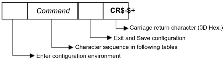
flowchart
graph TD
    A["Command"] --> B["CR-+"]
    B --> C["Carriage return character (0D Hex.)"]
    B --> D["Exit and Save configuration"]
    B --> E["Character sequence in following tables"]
    E --> F["Enter configuration environment"]
Example:
Multiple command programming sequence:
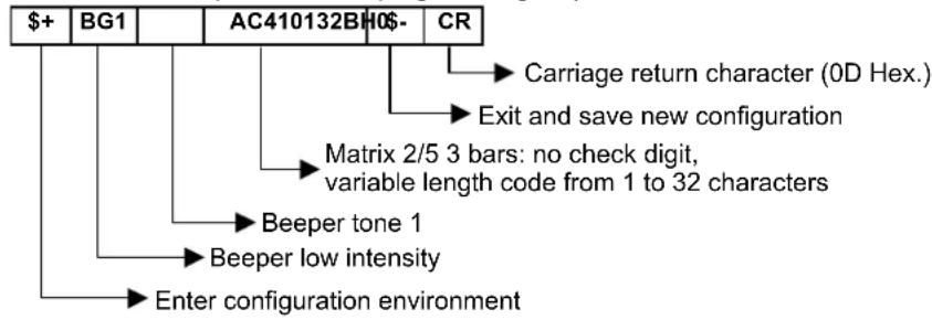
flowchart
graph TD
    A["$+"] --> B["BG1"]
    B --> C["AC410132BH0$-"]
    C --> D["CR"]
    D --> E["Carriage return character (0D Hex.)"]
    D --> F["Exit and save new configuration"]
    F --> G["Matrix 2/5 3 bars: no check digit, variable length code from 1 to 32 characters"]
    G --> H["Beeper tone 1"]
    H --> I["Beeper low intensity"]
    I --> J["Enter configuration environment"]
Each configuration parameter setting removes the condition previously active for that parameter.

The device buffer can contain about 400 characters. If your programming string goes over this value, you must split it into separate groups and send each group after a delay of at least 3 seconds to give the reader time to empty the buffer and interpret the commands.
Serial Configuration Strings
| SPECIAL CONFIGURATION COMMANDS | |
| DESCRIPTION | STRING |
| Enter Configuration | + |
| Exit and Save Configuration | - |
| Restore Default | +* |
| Transmit Software Release (not for PEN emulation) | +! |
| Transmit Device Configuration in ASCII (not for PEN emulation) | +& |
| Set Custom Default | +0 |
| Restore Custom Default | +1 |
These commands do not require \$-.
| INTERFACE SELECTION | |||
| DESCRIPTION | STRING | ||
| RS-232 | Standard | CP0 | |
| ICL Mode | CM0 | ||
| Fujitsu | CM1 | ||
| Nixdorf Mode A | CM2EC0 | ||
| WEDGE for | IBM AT | CP500 | |
| for IBM Terminals: 31xx, 32xx, 34xx, 37xx; make-break keyboard | CP501 | ||
| for IBM Terminals: 31xx, 32xx, 34xx, 37xx; make-only keyboard | CP502 | ||
| Keyboard Type for IBM Terminals 31xx, 32xx, 34xx, 37xx | typewriter | FK0 | |
| advanced | FK1 | ||
| for IBM XT | CP503 | ||
| for IBM Terminal 3153 | CP504 | ||
| for IBM PC Notebook | CP505 | ||
| for IBM SURE1 | CP506 | ||
| for IBM AT - ALT mode | CP507 | ||
| for IBM PC Notebook - ALT mode | CP508 | ||
| for Wyse Terminal - ANSI Keyboard | CP509 | ||
| for Wyse Terminal - PC Keyboard | CP510 | ||
| for Wyse Terminal - ASCII Keyboard | CP511 | ||
| for Wyse Terminal - VT220 style Keyboard | CP514 | ||
| for Digital Terminals VT2xx/3xx/4xx | CP512 | ||
| PEN EMULATION | CP6 | ||
| USB USB-KBD | UA03 | ||
| USB-KBD-ALT-MODE | UA04 | ||
| USB-KBD-APPLE | UA05 | ||
| USB-COM | UA02 | ||
| USB-IBM-Table Top | UA00 | ||
| USB-IBM-Hand Held | UA01 | ||
| RS-232 | ||
| DESCRIPTION | STRING | |
| Baud Rate 300 | CD1 | |
| 600 | CD2 | |
| 1200 | CD3 | |
| 2400 | CD4 | |
| 4800 | CD5 | |
| 9600 | CD6 | |
| 19200 | CD7 | |
| 38400 | CD8 | |
| Parity none | CC0 | |
| even | CC1 | |
| odd | CC2 | |
| Data Bits 7 | CA0 | |
| 8 | CA1 | |
| 9 | CA2 | |
| Stop Bits 1 | CB0 | |
| 2 | CB1 | |
| Handshaking disable | CE0 | |
| RTS/CTS | CE1 | |
| XON/XOFF | CE2 | |
| RTS always On | CE3 | |
| ACK/NACK Protocol disable | ER0 | |
| enable | ER1 | |
| FIFO disable | EC0 | |
| enable | EC1 | |
| Inter-character Delay(ms) | CK00 - CK99 | |
| RX Timeout (100 ms) | CL00 - CL99 | |
| Serial Trigger Lock | disable | CR0 |
| enable and select characters | CR1ab | |
a = Hex values representing an ASCII character from 00 to FE enabling the device trigger.
b = HEX values representing an ASCII character from 00 to FE inhibiting the device trigger.
| USB | ||
| DESCRIPTION | STRING | |
| USB-COM | ||
| Handshaking disable | CE0 | |
| RTS/CTS | CE1 | |
| XON/XOFF | CE2 | |
| RTS always ON | CE3 | |
| ACK/NACK Protocol disable | ER0 | |
| enable | ER1 | |
| FIFO disable | EC0 | |
| enable | EC1 | |
| Inter-character Delay (ms) | CK00 - CK99 | |
| RX Timeout (100 ms) | CL00 - CL99 | |
| Serial Trigger Lock disable | CR0 | |
| enable | CR1ab | |
| USB-KBD | ||
| Keyboard Nationality Belgian | FJ7 | |
| (not for USB-KBD-ALT-MODE) English (UK) | FJ4 | |
| French | FJ2 | |
| German | FJ3 | |
| Italian | FJ1 | |
| Spanish | FJ6 | |
| Swedish | FJ5 | |
| USA | FJ0 | |
| Keyboard Nationality Japanese | FJ8 | |
| (IBM AT compatible only) Russian (Latin) | FJ9 | |
| Russian (Cyrillic) | FJA | |
| Hungarian | FJB | |
| Slovenian, Croatian, Serbian (Latin) | FJC | |
| Romanian | FJD | |
| Czech Republic | FJE | |
| FIFO disable | EC0 | |
| enable | EC1 | |
| Delays Inter-Character | (ms) | CK00 - CK99 |
| Inter-Code (s) | FG00 - FG99 | |
| USB Keyboard Speed normal | UT10 | |
| fast | UT01 | |
a = Hex values representing an ASCII character from 00 to FE enabling the device trigger.
b = HEX values representing an ASCII character from 00 to FE inhibiting the device trigger.
| WEDGE | ||
| DESCRIPTION | STRING | |
| Keyboard Nationality Belgian | FJ7 | |
| English (UK) | FJ4 | |
| French | FJ2 | |
| German | FJ3 | |
| Italian | FJ1 | |
| Spanish | FJ6 | |
| Swedish | FJ5 | |
| USA | FJ0 | |
| Keyboard Nationality Japanese | FJ8 | |
| (IBM AT compatible only) Russian (Latin) | FJ9 | |
| Russian (Cyrillic) | FJA | |
| Hungarian | FJB | |
| Slovenian, Croatian, Serbian (Latin) | FJC | |
| Romanian | FJD | |
| Czech Republic | FJE | |
| Caps Lock caps Lock ON | FE1 | |
| caps Lock OFF | FE0 | |
| Caps Lock Auto-Recognition disable | FP0 | |
| (IBM AT compatible only) enable | FP1 | |
| Num Lock toggle num lock | FL1 | |
| num lock unchanged | FL0 | |
| Delays | Inter-Character (ms) | CK00 - CK99 |
| Inter-Code (s) | FG00 - FG99 | |
| Control Character Emulation | Ctrl + Shift + Key | FO0 |
| Ctrl + Key | FO1 | |
| PEN | ||
| DESCRIPTION | STRING | |
| Operating Mode interpret (does not require + or-) | ] | |
| transparent (does not require+ or -) | [ | |
| Minimum Output Pulse 200 | μs | DG0 |
| 400μs | DG1 | |
| 600μs | DG2 | |
| 800μs | DG3 | |
| 1 ms | DG4 | |
| 1.2 ms | DG5 | |
| Conversion to Code 39 and Code 128 | disable conversion to Code 39(D series only) | DA0 |
| enable conversion to Code 39 | DA1 | |
| enable conversion to Code 128(M series only) | DA2 | |
| Output Level normal | DD0 | |
| inverted | DD1 | |
| Idle Level normal | DE0 | |
| inverted | DE1 | |
| Overflow narrow overflow | DH0 | |
| medium overflow | DH1 | |
| wide overflow | DH2 | |
| Inter-block Delay(100 ms) | CK00-CK99 | |
| NETWORK | ||
| DESCRIPTION | STRING | |
| RS-485 Network Disable Network | RZ0 | |
| Enable RS-485 Slave | RZ1 | |
| Enable RS-485 Master | RZ2 | |
| Slave Address Range Minimum Address | JB0000-1999 | |
| Maximum Address | JC0000-1999 | |
| Network Baud Rate 9600 | JE0 | |
| 19200 | JE1 | |
| 38400 | JE2 | |
| Network Warning Message not transmitted | JG0 | |
| transmitted | JG1 | |
| Transmission Warning not transmitted | JH0 | |
| Message transmitted | JH1 | |
| Master Header no header | JA00 | |
| one character | JA01x | |
| two characters | JA02xx | |
| three characters | JA03xxx | |
| four characters | JA04xxxx | |
| five characters | JA05xxxxx | |
| six characters | JA06xxxxxxx | |
| seven characters | JA07xxxxxxx | |
| eight characters | JA08xxxxxxxx | |
| Master Terminator no terminator | JA10 | |
| one character | JA11x | |
| two characters | JA12xx | |
| three characters | JA13xxx | |
| four characters | JA14xxxx | |
| Five characters | JA15xxxxx | |
| six characters | JA16xxxxxx | |
| seven characters | JA17xxxxxxx | |
| eight characters | JA18xxxxxxx | |
x=Hex value from FE representing an ASCII character
| DATA FORMAT | ||
| NOT FOR PEN EMULATION INTERFACES | ||
| DESCRIPTION | STRING | |
| Code Identifier disable | EB0 | |
| Datalogic standard | EB1 | |
| AIM standard | EB2 | |
| custom | EB3 | |
| Custom Code Identifier | EHabc | |
| Headers no header | EA00 | |
| one character | EA01x | |
| two characters | EA02xx | |
| three characters | EA03xxx | |
| four characters | EA04xxxx | |
| five characters | EA05xxxxx | |
| six characters | EA06xxxxxx | |
| seven characters | EA07xxxxxxx | |
| eight characters | EA08xxxxxxxxx | |
| Terminators no terminator | EA10 | |
| one character | EA11x | |
| two characters | EA12xx | |
| three characters | EA13xxx | |
| four characters | EA14xxxx | |
| five characters | EA15xxxxx | |
| six characters | EA16xxxxxx | |
| seven characters | EA17xxxxxxx | |
| eight characters | EA18xxxxxxxxx | |
a = ASCII character.
b, c, x = HEX values representing an ASCII character.
a = ASCII character of the DATALOGIC STANDARD Code Identifier from the table in Appendix D.
b = Hex value of the first Custom Code Identifier character from 00 to FD;
FF = disable Code Identifier
c=Hex value of the second Custom Code Identifier character from 00 to FD;
FF = disable second character of Custom Code Identifier
x = Hex value from 00 to FE
| DATA FORMAT (continued) | ||
| NOT FOR PEN EMULATION INTERFACES | ||
| DESCRIPTION | STRING | |
| Code Length Tx not transmitted | EE0 | |
| transmitted in variable-digit format | EE1 | |
| transmitted in fixed 4-digit format | EE2 | |
| Field Adjustment disable | EF0 | |
| right addition | EFa0d | |
| left addition | EFa1d | |
| right deletion | EFa2d | |
| left deletion | EFa3d | |
| Field Adjustment Character | EGe | |
| Character Replacement disable character replacement | EO0 | |
| first character replacement | EO1afg | |
| second character replacement | EO2afg | |
| third character replacement | EO3afg | |
| Address Stamping disable reader address stamping | RU0 | |
| enable reader address stamping | RU1 | |
| disable cradle address stamping | RW0 | |
| enable cradle address stamping | RW1 | |
| Address Delimiter | disable reader address delimiter | RV0 |
| enable reader address delimiter and select character | RV1h | |
| disable cradle address delimiter | RY0 | |
| enable cradle address delimiter and select character | RY1h | |
| Time Stamping disable | IL0 | |
| hour/minutes/seconds/month/day/year | IL1 | |
| hour/minutes/seconds/day/month/year | IL2 | |
| hour/minutes/seconds | IL3 | |
| month/day/year | IL4 | |
| day/month/year | IL5 | |
| Time Stamping Delimiter disable time stamping delimiter | IM0 | |
| enable time stamping delimiter and select character | IM1h | |
a = ASCII character.
d = a number from the Hex/Numeric Table
e, f, g, h = HEX values representing an ASCII character
a=ASCII character of the DATALOGIC STANDARD Code Identifier from the table in Appendix D.
d=a number in the range 01-32 from the Hex/Numeric Table
e=Hex value from to FE
f= Hex value of the character to be replaced from 00 to FE
g = Hex value of the new character to insert from 00 to FE
FF = replace with no new character (remove character)
h = a HEX value in the range from 00 - FE representing the ASCII character.
| CODE SELECTION | |||
| DESCRIPTIONSTRING | |||
| Disable All Symbologies | AZA0 | ||
| Disable All Linear Symbologies | AXA0 | ||
| Disable All 2D Symbologies | AYA0 | ||
| Issue Identical Codes disabled | AWB0 | ||
| enabled | AWB1 | ||
| LINEAR SYMBOLOGIES | |||
| UPC/EAN/JAN disabled | AEA0 | ||
| enabled | AEA1 | ||
| Add-on | disabled | AEB0 | |
| enabled | AEB1 | ||
| UPCE extension enabled | AEC0 | ||
| disabled | AEC1 | ||
| Code 39 Standard disabled | ABA0 | ||
| no ccheck digit control | ABA1 | ||
| check digit control without transmission | ABA2 | ||
| check digit control and transmission | ABA3 | ||
| Full ASCII disabled | ABB0 | ||
| enabled | ABB1 | ||
| Code Len Check disabled | ABC0 | ||
| enabled | ABC1 | ||
| Minimum Code Length | ABDd | ||
| Maximum Code Length | ABEd | ||
| Start/Stop Char TX enabled | ABF0 | ||
| disabled | ABF1 | ||
| Code 32 disabled | ABL0 | ||
| enabled | ABL1 | ||
d = a number from the HEX/Numeric Table
d = a number in the range 001-255
| CODE SELECTION - LINEAR SYMBOLOGIES | |||
| DESCRIPTION | STRING | ||
| Interleaved 2/5 disabled | ACA0 | ||
| enabled – no check digit control | ACA1 | ||
| enabled – check digit control and without transmission | ACA2 | ||
| enabled – check digit control and transmission | ACA3 | ||
| Code Len Check disabled | ACB0 | ||
| enabled | ACB1 | ||
| Minimum Code Length | ACCd | ||
| Maximum Code Length | ACDd | ||
| Codabar disabled | ADA0 | ||
| enabled – no check digit control | ADA1 | ||
| enabled – check digit control and without transmission | ADA2 | ||
| enabled – check digit control and transmission | ADA3 | ||
| Code Len Check disabled | ADB0 | ||
| enabled | ADB1 | ||
| Minimum Code Length | ADCd | ||
| Maximum Code Length | ADDd | ||
| Code 128 disabled | AAA0 | ||
| enabled | AAA1 | ||
| Code Len Check disabled | AAB0 | ||
| enabled | AAB1 | ||
| Minimum Code Length | AACd | ||
| Maximum Code Length | AADd | ||
| EAN 128 disabled | AOA0 | ||
| enabled | AOA1 | ||
| Code Len Check disabled | AOB0 | ||
| enabled | AOB1 | ||
| Minimum Code Length | AOCd | ||
| Maximum Code Length | AODd | ||
| Code 93 disabled | AFA0 | ||
| enabled | AFA1 | ||
| Code Len Check disabled | AFB0 | ||
| enabled | AFB1 | ||
| Minimum Code Length | AFCd | ||
| Maximum Code Length | AFDd | ||
| GS1 DataBarTM Family | GS1 DataBar Expanded | disabled | AMA0 |
| enabled | AMA1 | ||
| GS1 DataBar Limited | disabled | AMB0 | |
| enabled | AMB1 | ||
| GS1 DataBar Omni-directional | disabled | AMC0 | |
| enabled | AMC1 | ||
| GS1 DataBar Expanded | disabled | AMD0 | |
| Stacked enabled | AMD1 | ||
| GS1 DataBar Stacked | disabled | AME0 | |
| enabled | AME1 | ||
d = a number from the HEX/Numeric Table
d = a number in the range 001-255
| CODE SELECTION - 2D SYMBOLOGIES | |||
| DESCRIPTION | STRING | ||
| PDF417 disabled | AGA0 | ||
| enabled | AGA1 | ||
| Macro PDF417 unbuffered mode | AVB0 | ||
| buffered mode | AVB1 | ||
| Micro PDF417 disabled | AGB0 | ||
| enabled | AGB1 | ||
| DataMatrix disabled | AHA0 | ||
| enabled | AHA1 | ||
| Minimum Code Length | AHCe | ||
| Maximum Code Length | AHDe | ||
| Rectangular Style disabled | AHE0 | ||
| enabled | AHE1 | ||
| QR Family disabled | AIA0 | ||
| enabled | AIA1 | ||
| Micro QR disabled | AIB0 | ||
| enabled | AIB1 | ||
| Postal Codes all disabled | ALA0 | ||
| Australian Post - enabled | ALA1 | ||
| Japan Post - enabled | ALA2 | ||
| PLANET - enabled | ALA3 | ||
| POSTNET - enabled | ALA4 | ||
| POSTNET with B and B' - enabled | ALA5 | ||
| POSTNET and PLANET - enabled | ALA6 | ||
| POSTNET with B and B' and PLANET - enabled | ALA7 | ||
| KIX Code - enabled | ALA8 | ||
| Royal Mail Code (RM4SCC) - enabled | ALA9 | ||
| Australian Table N Table | ALB0 | ||
| C Table | ALB1 | ||
| IMB disabled | ALC0 | ||
| enabled | ALC1 | ||
| Maxicode Mode 0 | disabled | AJL0 | |
| enabled | AJL1 | ||
| Mode 1 | disabled | AJM0 | |
| enabled | AJM1 | ||
| Mode 2 | disabled | AJN0 | |
| enabled | AJN1 | ||
| Mode 3 | disabled | AJO0 | |
| enabled | AJO1 | ||
| Mode 4 | disabled | AJP0 | |
| enabled | AJP1 | ||
| Mode 5 | disabled | AJQ0 | |
| enabled | AJQ1 | ||
| Mode 6 | disabled | AJR0 | |
| enabled | AJR1 | ||
| Aztec | disabled | AKA0 | |
| enabled | AKA2 | ||
| CODE SELECTION - 2D SYMBOLOGIES (continued) | ||
| DESCRIPTION | STRING | |
| Composite Code disabled | ANA0 | |
| enabled | ANA1 | |
| Discard Linear disabled | ANB0 | |
| Part enabled | ||
e = a number from the HEX/Numeric Table
e = a number in the range 0001-3600
| READING PARAMETERS | ||
| DESCRIPTION | STRING | |
| Trigger Mode trigger level | BAA0 | |
| trigger pulse | BAA1 | |
| Trigger Type normal trigger | BAB0 | |
| software trigger | BAB1 | |
| Flash On Duration | BB0f | |
| Flash Off Duration | BB1f | |
| Beeper Tone tone 1 | GBA1 | |
| tone 2 | GBA2 | |
| tone 3 | GBA3 | |
| tone 4 | GBA4 | |
| Beeper Volume off | GBB0 | |
| low | GBB1 | |
| medium | GBB2 | |
| high | GBB3 | |
| Beeper Duration | GBCf | |
| Reads per Cycle one read per cycle | BCA0 | |
| multiple reads per cycle | BCA1 | |
| Scan Timeout | BEAf | |
| User Defined Beeper Tone tone 1 | GBD1 | |
| tone 2 | GBD2 | |
| tone 3 | GBD3 | |
| tone 4 | GBD4 | |
| User Defined Beeper Volume off | GBE0 | |
| low | GBE1 | |
| medium | GBE2 | |
| high | GBE3 | |
| User Defined Beeper Duration | GBFf | |
| Perform User Defined Beep** | $?GGG | |
**this command carries out its specific function and does not need \+ and \-.
| CODE ORDERING AND SELECTION | ||
| Code per Scan one code per scan | BCB0 | |
| all codes per scan | BCB1 | |
| Central Code Transmission disabled | OAA0 | |
| enabled | OAA1 | |
| Order by Code Length disabled | OAB0 | |
| enabled - increasing order | OAB1 | |
| enabled - decreasing order | OAB2 | |
f = a number from the HEX/Numeric Table
f = a number in the range 01-99
| READING PARAMETERS | ||
| DESCRIPTION | STRING | |
| AUTOSCAN | ||
| Autoscan Mode | disabled | BBA0 |
| enabled in normal mode | BBA1 | |
| enabled in pattern mode | BBA2 | |
| Autoscan Aiming System | disabled | BBB0 |
| enabled | BBB1 | |
| Autoscan Hardware Trigger | disabled | BBC0 |
| enabled | BBC1 | |
| Autoscan Illumination System | disabled | BBD0 |
| enabled | BBD1 | |
| Safety Time | disabled | BGA0 |
| enabled | BGA1 | |
| Safety Time Duration | BGBf | |
| Good Read Spot | disabled | BIA0 |
| enable short | BIA1 | |
| enable medium | BIA2 | |
| enable long | BIA3 | |
| enable continuous | BIA4 | |
f = a number from the HEX/Numeric Table
f = a number in the range 01-99
| RADIO PARAMETERS | ||
| DESCRIPTION | STRING | |
| Radio Protocol Timeout enable (seconds) | RH02-RH19 | |
| Radio RX Timeout | RR00-RR99 | |
| Power-Off Timeout | RP00-RP99 | |
| Reader Shut-Downa | $?XYZ | |
| Transmission Mode | one-way | RI0 |
| two-way | RI1 | |
| Beeper Control For Radio Response | normal | BF0 |
| only good decode | BF1 | |
| only good reception | BF2 | |
| off | BF3 | |
| Single Store | disable | RO0 |
| one attempt | RO1 | |
| two attempts | RO2 | |
| three attempts | RO3 | |
| four attempts | RO4 | |
| five attempts | RO5 | |
| six attempts | RO6 | |
| seven attempts | RO7 | |
| eight attempts | RO8 | |
| nine attempts | RO9 | |
| Find Me | disable | Bk0 |
| enable | Bk1 | |
a. This command carries out its specific function and does not need \+ and \-.
| DISPLAY PARAMETERS | ||
| DESCRIPTION | STRING | |
| Date | IAddmmyy | |
| Time | IBhhmm | |
| Contrast | lighter | IC0 |
| darker | IC1 | |
| Font Size | small | ID0 |
| medium | ID1 | |
| large | ID2 | |
| Backlight | off | IE0 |
| on | IE1 | |
| Display-Off Timeout | IFa | |
| Display Mode | normal | IG0 |
| local echo | IG1 | |
| clear display after decode | IG2 | |
| Keypad | disabled keys | IK0 |
| enable and select KeyID characters | IK1bbb | |
ddmmyy = numbers from the Hex/Numeric Table representing day, month, year
hhmm = numbers from the Hex/Numeric Table representing hour, minutes
a = a number from the Hex/Numeric Table
b=HEX values representing an ASCII character
a=a number in the range 00-99 (sec.) from the Hex/Numeric Table
00 = Timeout disabled (always on).
b=3 Hex values from 00 to FE representing the left, center and right keys.
FF = KeyID disabled.
NOTES
Appendix C
Programming for Expert Users
This document is addressed to expert users who are familiar with software programming languages and want to define a personalized code formatting. The provided programming language allows creating either simple or complex formatting expressions by means of the basic functions connected together through the following operators: (, ), -, +.
The syntax to be used to transmit the expressions to the PowerScan® M8500 is the following:
\+ELBformatting expression\-
where:
is a number in the range 1-5 corresponding to the format to be defined; is the conventional character used as terminator of the command; - the formatting expression uses ASCII characters when containing text strings. For this reason, the string must be inserted between two quotation marks. The following example shows the ASCII conversion of the "ABC" string:
+ELB1 414243+#DS^C\- .$
Function Description
All the functions and conventions to be used within the formatting expressions are listed below:
| FUNCTION NAME DESCRIPTION | |
| FSTR | Searches for a defined substring by its starting and ending string. |
| FLSTR Searches for a defined substring by it | s starting string and its length. |
| SSTR Extracts a defined substring from the original string. | |
| FPOS Searches for a position of a defined substring within the original string. | |
| LSTR Returns a string length. | |
| ISTR Insert a substring in the original string. | |
| RSTR | Substitutes a defined substring contained in the original string with a new one. |
| CONVENTIONS DESCRIPTION | |
| + Concatenates two strings or fields. | |
| - Deletes a substring or a field from the original string. | |
| #DS Returns the string which has been decoded by the library. | |
| #F | Returns the result of a format which has been previously defined. Thevalue is in the range 1-4. |
FindStringByStarting&EndingChar (FSTR)
This function has the following syntax:
FSTR
This function searches for a substring having a defined starting character ("string_start") and a defined ending character ("string_stop") within the "source_string". It returns the string you searched for, or an empty one in case of failure.
If searching for a substring having characters already known, the "string_start" and "string_stop" arguments must share the same value.
The "mode" argument allows managing the starting character ("string_start") and the ending character ("string_stop"):
0 = include both starting and ending character
1 = include only starting character
2 = include only ending character
3 = discard both starting and ending character
FindStringByStartingChar&Len (FLSTR)
This function has the following syntax:
FLSTR
This function searches for a substring having a defined starting character ("string_start") and a defined length ("len") within the "source_string". It returns the string you searched for, or an empty one in case of failure.
If searching for a substring having a length already known, the "string_start" and "string_stop" arguments must share the same number.
The "mode" argument allows managing the starting character ("string_start"):
0 = include starting character
1 = discard starting character
SelectString (SSTR)
This function has the following syntax:
SSTR
It extracts a substring whose characters are between "pos_start" and "pos_end" from the "source_string".
If "pos_end" is longer than the "source_string" length, no error will be generated since the exceeding characters are ignored.
The first character of every string is in position 1.
FindPosition (FPOS)
This function has the following syntax:
FPOS
This function searches for a defined substring within the "source_string" and returns its position. If the substring is not found, the returned value is 1.
StringLength (LSTR)
This function has the following syntax:
LSTR
This function returns the length of the defined string.
StringConcatenation
This function has the following syntax:
string1 + string2→string
This function allows concatenating two different strings in order to get a single string as result.
StringDiscard
This function has the following syntax:
string1 - string2⇒string
This function discards all the strings having the same value as "string2" which can be found in "string1". If no "string2" is found within "string1", the result returns "string1".
InsertString (ISTR)
This function has the following syntax:
ISTR
This function inserts a new string ("string1") within the "source_string" and places it in the defined "position".
If the value of the "position" argument is longer than "source_string" length, "string1" will be placed after the last character of the source string.
ReplaceString (RSTR)
This function has the following syntax:
RSTR
This function searches for "string1" within the "source_string". All the strings having the same value as "string1" within the "source_string" will be replaced by "string2".
If no "string1" is found in the "source_string", the result returns the "source_string".
Examples
The string transmitted is "12345abcdef3790" and corresponds to the #DS function, as defined in the programming language.
- expression SSTR<#DS,1,5> + SSTR<#DS,11,15> + SSTR<#DS,6,9> result "12345f3790abcd"
2. expression ⇒ FSTR<#DS, }616263~, }616263~, 0> + SSTR<#DS,LSTR<#DS> -3, LSTR<#DS>
result ⇒ "abc3790"

3. expression ⇒ FS TR<#DS, }616272~, }616261~, 0>
result ⇒ "" null string

4. expression ⇒ # DS - FSTR<#DS, }616263~, }6566~, 0>
result "123453790"
During the format definition the decoded string represented by #DS does not change.
Using Format Output in Format Definition
The input used by the above functions to define the code formatting usually corresponds to the decoded code (#DS). Actually, the formatting expression of each function can also format the result (output) produced by a preceding code formatting.
The format output is represented as follows:
#F<n>, where:
<n> = format number in the range 1-4
#F = format output
Being Format 5 not included in other format expression, the format number is in the range 1-4. Furthermore, since a format expression operates upon the output of the preceding formats, the expression defining Format 1 will never contain the result of another format.
Example
The following expression is used to define Format 3:
#DS + FSTR<#F2, "6173", "6263", 0>
The expression input consists of the decoded code and the result produced by Format 2 (#F2).
The FSTR function searches for a defined substring within the #F2 result; then, it concatenates this substring and the decoded code. The result corresponds to #F3 output.
Appendix D
Code Identifier Table
EAN/UPC CODABAR


CODE 128 EAN 128


CODE 93 CODE 32


CODE 39 INTERLEAVED 2 OF 5


PDF417 MICRO PDF417


DATAMATRIX MAXICODE


QR MICRO QR


AUSTRALIA POST IMB


JAPAN POST POSTNET


PLANET GS1 DATABAR


KIX CODE RM4SCC


AZTEC

Appendix E
Sample Barcodes
The sample barcodes in this appendix are typical representations for their symbology types.
Test Code Symbols
Scan these 1D and 2D test symbols to check that the reader is imaging and decoding properly, according to your configuration.


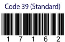

QR

PDF417

DataMatrix (Normal)

DataMatrix (Inverse)

Appendix F
Hex & Numeric Table
| CHARACTER TO HEX CONVERSION TABLE | ||||||||
| char decimal hex char decimal hex char decimal hex | ||||||||
| NUL | 000 00 | * | 042 2A | U | 085 55 | |||
| SOH | 001 01 | + | 043 2B | V | 086 56 | |||
| STX | 002 02 | , | 044 2C | W | 087 57 | |||
| ETX | 003 03 | - | 045 2D | X | 088 58 | |||
| EOT | 004 04 | . | 046 2E | Y | 089 59 | |||
| ENQ | 005 05 | / | 047 2F | Z | 090 5A | |||
| ACK | 006 06 | 0 | 048 30 | [ | 091 5B | |||
| BEL | 007 07 | 1 | 049 31 | \ | 092 5C | |||
| BS | 008 08 | 2 | 050 32 | ] | 093 5D | |||
| HT | 009 09 | 3 | 051 33 | ^ | 094 5E | |||
| LF | 010 0A | 4 | 052 34 | _ | 095 5F | |||
| VT | 011 0B | 5 | 053 35 | ` | 096 60 | |||
| FF | 012 0C | 6 | 054 36 | a | 097 61 | |||
| CR | 013 0D | 7 | 055 37 | b | 098 62 | |||
| SO | 014 0E | 8 | 056 38 | c | 099 63 | |||
| SI | 015 0F | 9 | 057 39 | d | 100 64 | |||
| DLE | 016 10 | : | 058 3A | e | 101 65 | |||
| DC1 | 017 11 | ; | 059 3B | f | 102 66 | |||
| DC2 | 018 12 | < | 060 3C | g | 103 67 | |||
| DC3 | 019 13 | = | 061 3D | h | 104 68 | |||
| DC4 | 020 14 | > | 062 3E | i | 105 69 | |||
| NAK | 021 15 | ? | 063 3F | j | 106 6A | |||
| SYN | 022 16 | @ | 064 40 | k | 107 6B | |||
| ETB | 023 17 | A | 065 41 | l | 108 6C | |||
| CAN | 024 18 | B | 066 42 | m | 109 6D | |||
| EM | 025 19 | C | 067 43 | n | 110 6E | |||
| SUB | 026 1A | D | 068 44 | o | 111 6F | |||
| ESC | 027 1B | E | 069 45 | p | 112 70 | |||
| FS | 028 1C | F | 070 46 | q | 113 71 | |||
| GS | 029 1D | G | 071 47 | r | 114 72 | |||
| RS | 030 1E | H | 072 48 | s | 115 73 | |||
| US | 031 1F | I | 073 49 | t | 116 74 | |||
| SPACE | 032 20 | J | 074 4A | u | 117 75 | |||
| ! | 033 21 | K | 075 4B | v | 118 76 | |||
| " | 034 22 | L | 076 4C | w | 119 77 | |||
| # | 035 23 | M | 077 4D | x | 120 78 | |||
| $ | 036 24 | N | 078 4E | y | 121 79 | |||
| % | 037 25 | O | 079 4F | z | 122 7A | |||
| & | 038 26 | P | 080 50 | { | 123 7B | |||
| ' | 039 27 | Q | 081 51 | | | 124 7C | |||
| ( | 040 28 | R | 082 52 | } | 125 7D | |||
| ) | 041 29 | S | 083 53 | ~ | 126 7E | |||
| T | 084 54 | DEL | 127 7F | |||||
| CHARACTER TO HEX CONVERSION TABLE (continued) | ||||||||
| char decimal hex char | decimal hex char | hex char decimal hex | ||||||
| € | 128 80 | a | 170 AA | O | 213 D5 | |||
| □ | 129 81 | « | 171 AB | Ö | 214 D6 | |||
| , | 130 82 | ¬ | 172 AC | x | 215 D7 | |||
| ENTER | 131 83 | - | 173 AD | ∅ | 216 D8 | |||
| TAB | 132 84 | ° | 174 AE | Ü | 217 D9 | |||
| F1 | 133 85 | - | 175 AF | Ü | 218 | DA | ||
| F2 | 134 86 | ° | 176 B0 | Ü | 219 DB | |||
| F3 | 135 87 | ± | 177 B1 | Ü | 220 | DC | ||
| F4 | 136 88 | 2 | 178 B2 | Y | 221 | DD | ||
| F5 | 137 89 | 3 | 179 B3 | p | 222 DE | |||
| F6 | 138 8A | ' | 180 B4 | ß | 223 DF | |||
| F7 | 139 8B | μ | 181 B5 | à | 224 E0 | |||
| F8 | 140 | 8C | ¶ | 182 B6 | á | 225 E1 | ||
| F9 | 141 8D | . | 183 B7 | â | 226 E2 | |||
| F10 | 142 8E | , | 184 B8 | ä | 227 E3 | |||
| F11 | 143 8F | 1 | 185 B9 | ä | 228 E4 | |||
| F12 | 144 90 | ° | 186 BA | å | 229 E5 | |||
| HOME | 145 91 | » | 187 BB | æ | 230 E6 | |||
| END | 146 92 | 1⁄4 | 188 BC | ç | 231 E7 | |||
| Pg UP | 147 93 | 1⁄2 | 189 BD | è | 232 E8 | |||
| Pg Down | 148 94 | 3⁄4 | 190 | BE | é | 233 E9 | ||
| ↑ | 149 95 | ¿ | 191 | BF | ê | 234 | EA | |
| ↑ | 150 96 | À | 192 C0 | ë | 235 EB | |||
| ← | 151 97 | Á | 193 C1 | ì | 236 | EC | ||
| → | 152 98 | Â | 194 C2 | í | 237 ED | |||
| ESC | 153 99 | Ä | 195 C3 | î | 238 | EE | ||
| CTRL(Right) | 154 9A | Ä | 196 C4 | ï | 239 | EF | ||
| € | 155 | 9B | Ä | 197 C5 | ð | 240 F0 | ||
| œ | 156 | 9C | Æ | 198 C6 | ñ | 241 F1 | ||
| □ | 157 9D | Ç | 199 C7 | ò | 242 F2 | |||
| ž | 158 9E | È | 200 C8 | ó | 243 F3 | |||
| Ÿ | 159 9F | É | 201 C9 | ô | 244 F4 | |||
| NBSP | 160 A0 | É | 202 CA | ö | 245 F5 | |||
| i | 161 A1 | É | 203 CB | ö | 246 F6 | |||
| ç | 162 A2 | I | 204 CC | ÷ | 247 F7 | |||
| £ | 163 A3 | í | 205 CD | ø | 248 F8 | |||
| α | 164 A4 | Í | 206 CE | ù | 249 F9 | |||
| ¥ | 165 A5 | ï | 207 CF | ú | 250 FA | |||
| ¡ | 166 A6 | Đ | 208 D0 | ù | 251 FB | |||
| § | 167 A7 | Ñ | 209 D1 | ü | 252 | FC | ||
| .. | 168 A8 | ò | 210 D2 | ý | 253 FD | |||
| © | 169 A9 | Ó | 211 D3 | Reserved | 254 | FE | ||
| Ô | 212 D4 | Reserved | 255 | FF | ||||
HEX NUMERIC TABLE
0

1

2

3

4

5

6

7

8

9

A

B

C

D

E

F

AUTOSCAN PATTERN CODE

NOTES
NOTES
NUMERICS
2D Matrix symbol 18
A
About this Guide 7_
ACK/NACK Protocol 58, 61, 156
Address Delimiter 92, 168
Address Stamping 91,168
Aiming System 9,18,103
Aladdin™ 19
All Codes Per Scan 21, 22
Alphanumeric Keyboard Setting 71
Alt Mode 49
Australian Table Selection 115
Autoscan 122
Aiming System 122
Autoscan Aiming System 122
Autoscan Mode 122
Hardware Trigger 122
Illumination System 122
Autoscanning 20
Normal Mode 20
Pattern Mode 20
Aztec code 116
B
Backlight 132
Batch Mode 129, 172
battery
WARNINGS 29
Battery Charging 28
Baud Rate 56
Network 80
BC-8060
Master Layout 38
Network Connectors 26
STAR-System™ Network Setup 45
BC-80X0
Interface Cable 23
BC-80X0 / C-8000 184
Cradles 17
BC-80X0 / C-8000 CRADLES 17
BC-80X0/C-8000
Charge Status 188
Power/Communication 188
Beeper 186
Duration 119
Tone 118
User Defined 120
Volume 119
Beeper Control for Radio Response 127, 171
C
Camera Control
Exposure and Calibration 20
Caps Lock 69
Central Code Transmission 121
Character Deletion 98
Character Substitution 97
Clearing Display 177
Codabar Family 108
Code 128 Family 109
Code 32 Family 107
Code 39 Family 106
Code 93 Family 110
Code Identifier 85
Code Length Tx 91
Code Ordering and Selection 121
Codes per Scan 121
Composite Codes 116
Concatenation 22
Define 99
Enable/Disable 99
Failure Transmission 100
Intercode Delay 100
Length 99
Result Code ID 101
Timeout 100
Transmission After Timeout 101
Configuration Editing Commands 169
Connections
Network 26
Contrast 131
Control Character Emulation 73
Conversion to Code 39 76
Conversion to Code 39 and Code 128 77, 157
Cursor Control 176
Custom Code Identifier 86
D
Data Bits 57
Data Format 84,160
Datalogic Aladdin™ 19
DataMatrix Family 113
Date and Time 131
Default Key Identifiers 178
Default Parameters for POS Terminals 174
Default Settings 189
Defining Special Key Sequences 166
Desktop Mounting 31
DIGITAL TERMINALS 50
Display Mode 132, 173
Display Parameters 173
Display-Off Timeout 132
Driver License Parsing 15
E
Exposure and Calibration 20
Exposure Mode 102
F
Field Deletion 148
Field Extraction by Character 139, 140
FIFO 58, 61, 65, 156
Find Me 129, 172
FindPosition (FPOS) 211
Fixed Desktop Use 32
Flash Mode 118
Font Selection 177
Font Size 131
Format Definition 136
Format Enable/Disable 152
G
General View 16
Good Read Spot 187
GS1 Databar™ 111
H
Handshaking 57, 61, 155
Header 89
Header/Terminator Selection 160
Hex & Numeric Table 217
Host Configuration Strings 193
Host Master Layout 37
I
IBM 31xx, 32xx, 34xx, 37xx 160
IBM Terminals 31xx, 32xx, 34xx, 37xx
Interface 48
IBM USB POS 24
Idle Level 78
Indicators 186
Installation 23
Integrating Special Keys in Headers/Terminators 167
Inter-Block Delay 78, 158
Inter-character Delay 58, 62, 66, 70
Inter-code Delay 66,71
Interface
IBM Terminals 31xx, 32xx, 34xx, 37xx 48
PEN 47
POS Terminals 47
RS-232 47
Wedge 48
Interface Selection 47
Interleaved 2 of 5 Family 107
Issue Identical Codes 104
K
Key Transmission Mode 48
Keyboard Nationality 64, 68
Keyboard Setting 71
Keyboard Type 49
KeyID 178
Keypad 133
L
LED and Beeper Control 177
Linear Symbologies 105
M
Master Cradle Header 82
Master Cradle Terminator 83
Master Header/Terminator Selection 159
Match Conditions 151
Maxicode Family 115, 116
Message Formatting 175
Messages from Host to Reader 175
Micro PDF417 113
Minimum Output Pulse 76, 157
Mismatch Result 153
N
Network
Baud Rate 80
Cabling 26
Connections 26
Parameters 158
Termination 27
Troubleshooting 38
Warning Message 81, 159
Normal Mode 20
Num Lock 70
0
Omni-directional Operating 15
One Code Per Scan 21
Operating Mode 75
Order By Code Length 121
Order By Code Symbology 121
Output and Idle Levels 158
Output Level 77
Overflow 77
P
Parity 56
Pattern Mode 20
PDF417 112
PEN 74
PEN Emulation Connection 25
Pen Interface 47
Portable Desktop Use 31
POS Terminals
Interface 47
Postal Codes 114
Power Supply 12
Power-Off Timeout 126, 170
Product Specifications 179
Q
QR Family 113, 114
R
Radio Parameters 124, 170, 206
Radio Protocol Timeout 125, 170
Radio RX Timeout 125, 170
Reading Configuration Barcodes 54
Reading Parameters 168
Reads per Cycle 119, 168
Reception Warning Message 81, 159
RS-232
Baud Rate 56
Data Bits 57
Handshaking 57
Interface 47
PARAMETERS 55
Parity 56
Stop Bits 57
RS-232 Connection 24
RX Timeout 59,62,157
S
Safety Time 123,169
Scan Timeout 119
Serial Configuration Strings 194
Serial Trigger Lock 59, 63
Service & Support 8_
Setting RTC 177
Setup Procedures 39
Single Store 128,171
Slave Address Range 81, 158
Software handshaking
(XON/XOFF) 155
Stand-Alone Layouts 35
Standard Message Formatting 175
Stop Bits 57
String Deletion Procedure 145
String Insertion Procedure 143
Symbology Character Deletion 97
Symbology Character Substitution 97
Symbology Headers 95
Symbology Specific Format Default 98
Symbology types 215
System and Network Layouts 35
T
Terminator 90, 96
Test Code Symbols 215
Test User Defined Beeper 120
Time Stamping 92
Time Stamping Delimiter 168
Time Stamping Format 168
Transmission After Timeout 101
Transmission Mode 126, 171
Trigger
Mode 118
Signal 168
Type 118
U
UPC/EAN/JAN Family 105
USB 24
USB Connection 24
USB Keyboard Speed 66
USB PARAMETERS 60
USB Parameters 60
USB Reader Configuration 50
USB Start-up 50
USB-COM 61
ACK/NACK Protocol 61
Handshaking 61
USB-KBD 64
User Defined Beeper 120
Using Multiple M-Series Readers with Same
Cradle 42
Using the Reader 18
W
Wall Mounting 33
Warning Message, Network 81, 159
Wedge 48,197
Connection 25
Interface 48
Parameters 67
WEEE Compliance 13
WYSE Terminals 49
X
XON/XOFF
Software handshaking 155
Australia
Datalogic Scanning Pty Ltd
Telephone: [61] (2) 9870 3200
australia.scanning@datalogic.com
France and Benelux
Datalogic Scanning Sarl
Telephone: [33].01.64.86.71.00
france.scanning@datalogic.com
Germany
Datalogic Scanning KK
Telephone: 81 (0)3 3491 6761
japan.scanning@datalogic.com
Latin America
Datalogic Scanning, Inc
Telephone: (305) 591-3222
latinamerica.scanning@datalogic.com
Singapore
Datalogic Scanning Singapore PTE LTD
Telephone: (65) 6435-1311
singapore.scanning@datalogic.com
Spain and Portugal
Datalogic Scanning Sarl Sucursal en España
Telephone: 34 91 746 28 60
spain.scanning@datalogic.com
United Kingdom
Datalogic Scanning LTD
Telephone: 44 (0) 1923 809500
uk.scanning@datalogic.com

text_image
DATALOGIC™www.scanning.datalogic.com
Datalogic Scanning, Inc.
959 Terry Street
Eugene, OR 97402
USA
Telephone: (541) 683-5700
Fax: (541) 345-7140
