IES-1248-51A ADSL 2+ - Router ZYXEL - Free user manual and instructions
Find the device manual for free IES-1248-51A ADSL 2+ ZYXEL in PDF.

User questions about IES-1248-51A ADSL 2+ ZYXEL
0 question about this device. Answer the ones you know or ask your own.
Ask a new question about this device
Download the instructions for your Router in PDF format for free! Find your manual IES-1248-51A ADSL 2+ - ZYXEL and take your electronic device back in hand. On this page are published all the documents necessary for the use of your device. IES-1248-51A ADSL 2+ by ZYXEL.
USER MANUAL IES-1248-51A ADSL 2+ ZYXEL
Provide Different DSL Port Speeds to different subscribers.... 4
How to apply the profile to ports....4
How to configure 802.1Q VLAN....10
How to set up a VLAN environment. 11
Triple play Application 14
How to set up a Multiple PVCs environment.... 15
802.1x Application.... 23
How to set up an 802.1x environment.... 23
Setting up the Syslog Server 28
How to set up a Syslog server.... 28
Setting up the Ring Environment 30
How to set up a Ring Environment.... 31
Setting up the IGMP Snooping/IGMP Filtering....37
How to set up IGMP snooping/IGMP filtering.... 38
Static Multicast....40
How to configure Static Multicast filter 42
Limit the users behind the certain DSL port 46
How to set up MAC Filter/Port Security 47
DHCP Relay Option 82 Application....49
How to set up DHCP Relay Option 82 Environment .... 50
Filter Some Certain Packet 60
How to Filter Some Specific Packet....60
Cascade two IES1248 (Daisy chain mode)....62
How to setup Daisy-chain mode.... 62
VLAN Application 63
How to configure VLAN: 64
FAQ 80
What is the maximum line rate of IES1248 ? 80
How many management instances can access IES-1248 at the same time?...... 80
What is the difference between IES1248-71 and IES1248-73 ? ...... 80
What is the power requirement of IES- 1248? 80
What kind of the DSL standard does IES1248 compliant ?...... 80
What is the ADSL chipset of IES1248? 80
What is the Network Processor of IES1248 ? 80
How many Flash memory and SDRAM that IES 1248 supports? 80
What kind of the features that IES 1248 supports ?......81
What is the default console rate of IES1248 ? 81
How many static VLAN entries can IES1248 support ? 81
How many VLANs can each ADSL port of IES1248 join ? 81
How many VLANs can each ADSL port of IES1248 join ? 81
What kinds of profiles can IES1248 supprot? 81
Trouble Shooting....83
If my computer can't access the DSLAM by WEB/Telnet/Ping from Ethernet port, only console screen can access successfully, what can I do?...... 83
If DHCP Relay Option 82 can't work, for example, PC can not get desired IP address from DHCP server, what can I do?...... 85
How to reset this device as factory default? 85
xDSL link fail? 90
Which new version I should upgrade? 90
I forgot the Password, how do I recover it? 91
I can not access the DSLAM via console port. What should I do?...... 91
There is no traffic could be transmitted through the DSLAM, what should I do?...... 92
Alarm Led is always on, what should I do? 92
Application Notes
Provide Different DSL Port Speeds to different subscribers
An ISP may provide different Line speeds for each DSL port. In our IES-1248 have an easy way to configure the line speed for each port. It can create some profiles which can set different parameters to meet the different users' requirement. In this application, we will set up two profiles. One is for low speed requirement with upstream/downstream is 2M/512Kbps and the other is for high speed requirement with upstream/downstream is 25M/1.2Kbps. We suppose there are general subscribers from port 1 to port 24 with a low speed profile and some enterprise users from port 25 to port 48 with high speed profile.
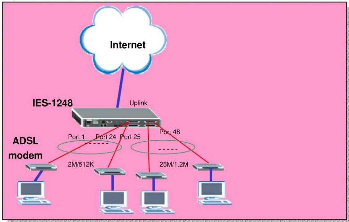
flowchart
graph TD
    A["Internet"] --> B["IES-1248"]
    B --> C["Uplink"]
    C --> D["ADSL modem"]
    D --> E["2M/512K"]
    D --> F["Port 1"]
    D --> G["Port 24"]
    D --> H["Port 25"]
    D --> I["Port 48"]
    D --> J["25M/1.2M"]
How to apply the profile to ports
In this application, we need to configure IES1-1248 and ADSL CPE. We use ZyXEL Prestige 660R-61 CPE here.
1. IES-1248 Settings
1.1 Profiles settings
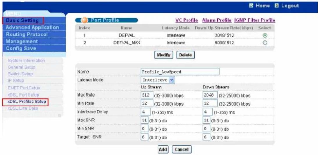
Click Basic Setting, xDSL Profiles Setup in the navigation panel to display configuration screen as shown.
text_image
Home Logout Basic Setting Advanced Application Routing Protocol Management Config Save System Information General Setup Switch Setup IP Setup ENET Port Setup xDSL Port Setup xDSL Profile Setup Add Cancel Port Profile VC Profile Alarm Profile IGMP Filter Profile Index Name Latency Mode Down/ Up Stream Rate( kbps) Select 1 DEFVAL Interleave 2048/512 2 DEFVAL_MAX Interleave 9008/512 Modify Delete Name Profile_LowSpeed Latency Mode Interleave Up Stream Down Stream Max Rate 512 (32-3000) kbps 2048 (32-25000) kbps Min Rate 32 (32-3000) kbps 32 (32-25000) kbps Interleave Delay 4 (1-255) ms 4 (1-255) ms Max SNR 31 (0-31) db 31 (0-31) db Min SNR 0 (0-31) db 0 (0-31) db Target SNR 6 (0-31) db 6 (0-31) db Add CancelSet up Low Speed Profile. Give this profile a name like Profile_LowSpeed and input the MaxRate for Up Stream and Down Stream. In this case, we set 512Kbps and 2048Kbps for Up Stream and Down Stream.

text_image
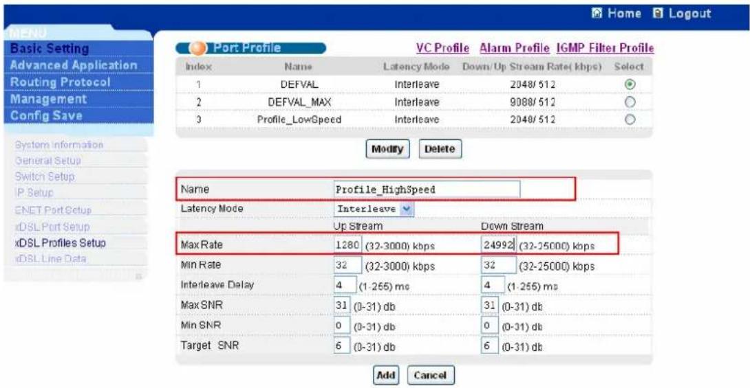
PORT Profile VC Profile Alarm Profile IGMP Filter Profile Index Name Latency Mode Down/ Up Stream Rate( kbps) Select 1 DEFVAL Interleave 2048/ 512 2 DEFVAL_MAX Interleave 9088/ 512 Modify Delete Name Profile_LowSpeed Latency Mode Interleave Up Stream Down Stream Max Rate 512 (32-3000) kbps 2048 (32-25000) kbps Min Rate 32 (32-3000) kbps 32 (32-25000) kbps Interleave Delay 4 (1-255) ms 4 (1-255) ms Max SNR 31 (0-31) db 31 (0-31) db Min SNR 0 (0-31) db 0 (0-31) db Target SNR 6 (0-31) db 6 (0-31) db Add CancelSet up High Speed Profile. Give this profile a name like Profile_HighSpeed and input the MaxRate for Up Stream and Down Stream. In this case, we set 1280Kbps and 24992Kbps for Up Stream and Down Stream.
text_image
Home Logout Basic Setting Advanced Application Routing Protocol Management Config Save System Information General Setup Switch Setup IP Setup ENET Port Setup xDSL Port Setup xDSL Profiles Setup xDSL Line Data Port Profile VC Profile Alarm Profile IGMP Filter Profile Index Name Latency Mode Down/Up Stream Rate( kbps) Select 1 DEFVAL Interleave 2048/512 2 DEFVAL_MAX Interleave 9088/512 3 Profile_LowSpeed Interleave 2048/512 Modify Delete Name Profile_HighSpeed Latency Mode Interleave Up Stream Down Stream Max Rate 1280 (32-3000) kbps 24992 (32-25000) kbps Min Rate 32 (32-3000) kbps 32 (32-25000) kbps Interleave Delay 4 (1-265) ms 4 (1-265) ms Max SNR 31 (0-31) db 31 (0-31) db Min SNR 0 (0-31) db 0 (0-31) db Target SNR 6 (0-31) db 6 (0-31) db Add Cancel1.2 Profile Assignment
Click Basic Setting, xDSL Port Setup in the navigation panel to display configuration screen as shown.

text_image
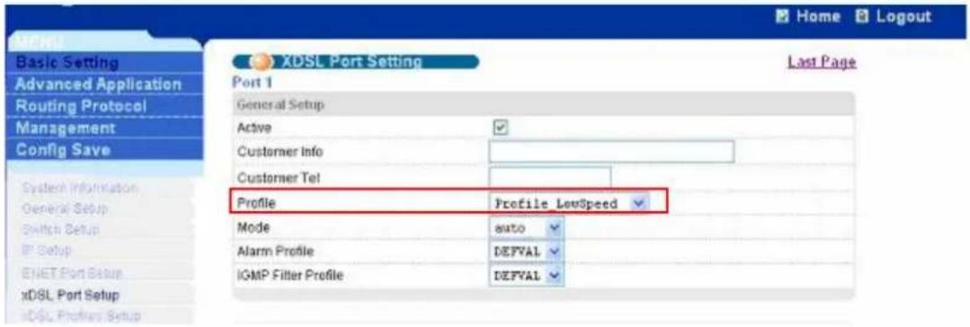
ZyXEL Home Logout MENU Basic Setting Advanced Application Routing Protocol Alarm Management Config Save System Information General Setup User Account Switch Setup IP Setup ENET Port Setup xDSL Port Setup xDSL Profiles Setup xDQL Line Data xDSL Port Setup Active Customer Info Customer Tel 2+ Features settings Paste Copy Port Profile&Mode IGMP filter Security Frame Type Virtual Channels Alarm Profile PyIDS&Priority Packet Filter Port Active Customer Info Customer Tel Profile Mode Channels 1 enabled DEFYAL_MAX auto 1 2 enabled DEFYAL_MAX auto 1 3 enabled DEFYAL_MAX auto 1 4 enabled DEFYAL_MAX auto 1 5 enabled DEFYAL_MAX auto 1 6 enabled DEFYAL_MAX auto 1 7 enabled DEFYAL_MAX auto 1 8 enabled DEFYAL_MAX auto 1 9 enabled DEFYAL_MAX auto 1 10 enabled DEFYAL_MAX auto 1 11 enabled DEFYAL_MAX auto 1Assign Profile_LowSpeed to port 1. Click a number 1 in the Port index field to enter Port setup screen. Select the Profile_LowSpeed profile and press Apply button.
text_image
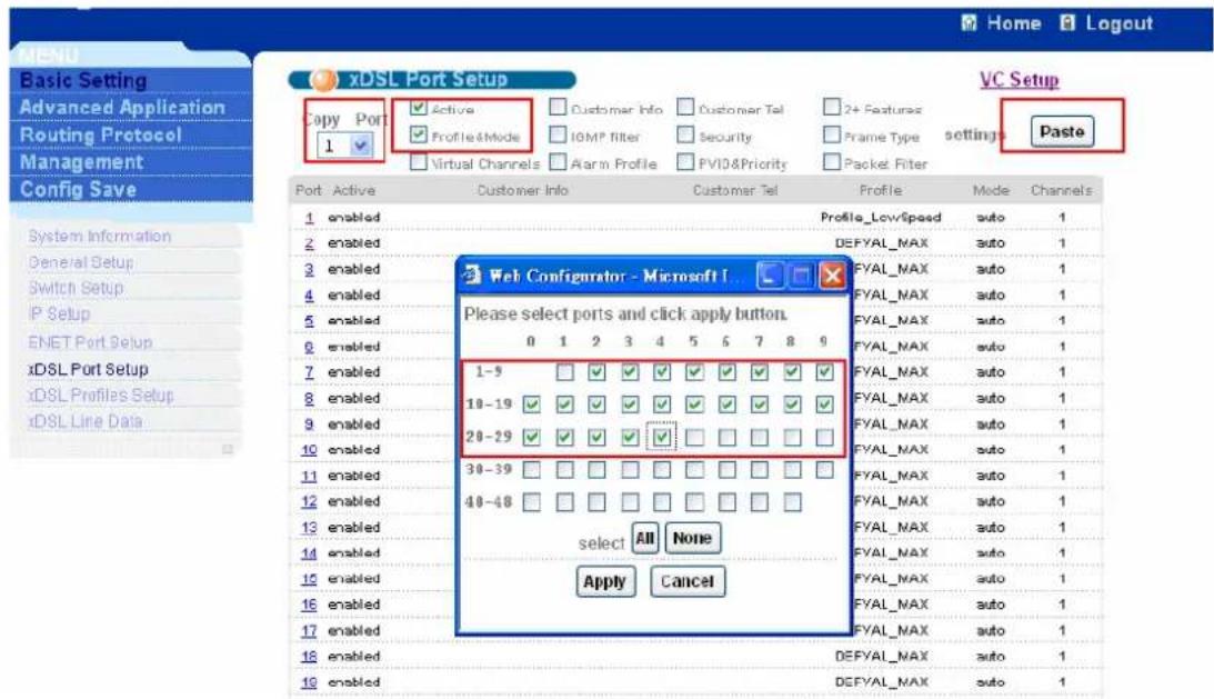
Basic Setting Advanced Application Routing Protocol Management Config Save System Information General Setup Switch Setup IP Setup ENET Port Setup xDSL Port Setup xDSL Port Setup XDSL Port Setting Last Page Port 1 General Setup Active Customer Info Customer Tel Profile Profile LowSpeed Mode auto Alarm Profile DEFVAL IGMP Filter Profile DEFVALCopy the settings of port 1 to the ports from 2 to 24. After finishing port 1 setting, the screen will be back to the xDSL port Setting screen. Select port 1 in Copy Port
combobox. Check the Active and Profile&Mode. After press the Paste button. It will pop up a screen to select the ports. Select the ports you want to copy the configuration to and press Apply button. The settings of port 1 will be copied to other ports.
text_image
xDSL Port Setup Copy Port 1 Active Profile&Mode Virtual Channels Customer Info IGMP Filter Alarm Profile Customer Tel Security PVIO&Priority 2+ Features Frame Type Packet Filter Settings Paste VC Setup Port Active Customer Info Customer Tel Profile Mode Channels 1 enabled Profile_LowSpeed auto 1 2 enabled DEFYAL_MAX auto 1 3 enabled FYAL_MAX auto 1 4 enabled FYAL_MAX auto 1 5 enabled FYAL_MAX auto 1 6 enabled FYAL_MAX auto 1 7 enabled FYAL_MAX auto 1 8 enabled FYAL_MAX auto 1 9 enabled FYAL_MAX auto 1 10 enabled FYAL_MAX auto 1 10 enabled FYAL_MAX auto 1 10 enabled FYAL_MAX auto 1 10 enabled FYAL_MAX auto 1 10 enabled FYAL_MAX auto 1 10 enabled FYAL_MAX auto 1 10 enabled FYAL_MAX auto 1 10 enabled FYAL_MAX auto 1 10 enabled FYAL_MAX auto 1 10 enabled FYAL_MAX auto 1 18 enabled DEFYAL_MAX auto 1 19 enabled DEFYAL_MAX auto 1For the high speed profile, you can set the Profile_HighSpeed to port 25. You also can select ADSL2+ mode in Mode combobox. That will fix the mode on ADSL2+ mode.

text_image
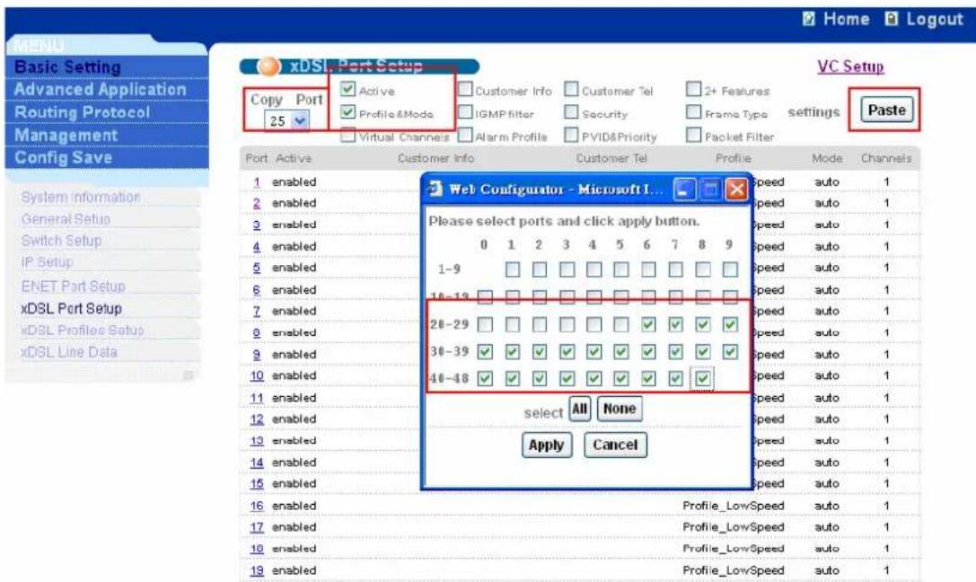
Basic Setting Advanced Application Routing Protocol Management Config Save System Information General Setup Switch Setup IP Setup ENET Port Setup xDSL Port Setup XDSL Port Setting Last Page Port 25 General Setup Active Customer Info Customer Tel Profile Profile_HighSpeed Mode ads12+ Alarm Profile DEFVAL IGMP Filter Profile DEFVALCopy the settings of port 25 to the ports from 26 to 48. You can follow the same procedures as port 1.
text_image
Home Logout MENU Basic Setting Advanced Application Routing Protocol Management Config Save xDSL - Port Setup Copy Port 25 Active Profile&Mode Virtual Channels Customer Info IGMP filter Alarm Profile Customer Tel Security PVID&Priority 2+ Features Frame Type Packet Filter VC Setup settings Paste Port Active Customer Info Customer Tel Profile Mode Channels 1 enabled 2 enabled 3 enabled 4 enabled 5 enabled 6 enabled 7 enabled 8 enabled 9 enabled 10 enabled 11 enabled 12 enabled 13 enabled 14 enabled 15 enabled Web Configurator - Microsoft I... Please select ports and click apply button. 0 1 2 3 4 5 6 7 8 9 1-9 10-13 20-29 30-39 40-48 select All None Apply Cancel Speed auto 1 Speed auto 1 Speed auto 1 Speed auto 1 Speed auto 1 Speed auto 1 Speed auto 1 Speed auto 1 Speed auto 1 Speed auto 1 Speed auto 1 Speed auto 1 Profile_LowSpeed auto 1 Profile_LowSpeed auto 1 Profile_LowSpeed auto 1 Profile_LowSpeed auto 12. Prestige 660R-61 Settings
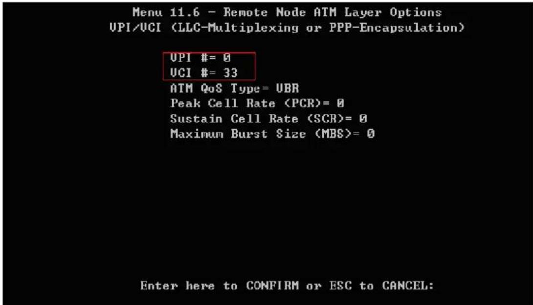
We configure Prestige 660R-61 as bridge mode. The default VPI/VCI of IES-1248 is 0/33. So we need to set up such values. Prestige 660R-61 has a Telnet server inside. We need to configure it via Telnet.
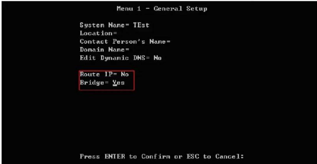
2.1 Menu1: General Setup
Go to Menu 1. In this menu, we must set "Rout IP = NO" and "Bridge = YES".
text_image
Menu 1 - General Setup System Name= TEst Location= Contact Person's Name= Domain Name= Edit Dynamic DMS= No Route IP= No Bridge= Yes Press ENTER to Confirm or ESC to Cancel:2.2 Menu4: Internet Access Setup
The encapsulation must be RFC 1483 for bridge mode. The Multiplexing should be the same as IES-1248. The LLC-based is default mode of IES1248. Additionally, we must check if the VPI/VCI is the same as IES-1248. The default VPI/VCI of IES1248 is 0/33.
Menu 4 - Internet Access Setup
ISP's Name= MyISP
Encapsulation= RFC 1483
Multiplexing= LLC-based
UPI #= 0
UCI #= 33
HIM QoS Type= UBR
Peak Cell Rate (PCR)= 0
Sustain Cell Rate (SCR)= 0
Maximum Burst Size (MBS)= 0
My Login= N/A
My Password= N/A
ENET ENCAP Gateway= N/A
IP Address Assignment= Static
IP Address= 0.0.0.0
Network Address Translation= SUA Only
Address Mapping Set= N/A
Press ENTER to Confirm or ESC to Cancel:
2.3 Menu11.1: Remote Node Profile
In menu11.1, we should activate this profile with “Active= Yes”. The Encapsulation and the Multiplexing are the same as the menu 4. Setting “Edit ATM Options=Yes” will enter Menu 11.6.
Menu 11.1 - Remote Node Profile
Rem Node Name = MyISP
Active = Yes
Route = None
Bridge = Yes
Encapsulation= RFC 1483
Multiplexing= LLC-based
Edit IP/Bridge= No
Edit ATM Options= Yes
Service Name= N/A
Incoming:
Edit Advance Options= N/A
Telco Option:
Rem Login= N/A
Rem Password= N/A
Allocated Budget(min) = N/A
Period(hr) = N/A
Outgoing:
My Login = N/A
My Password = N/A
Authen = N/A
Schedule Sets = N/A
Nailed-Up Connection = N/A
Press ENTER to Confirm or ESC to Cancel:
2.4 Menu11.6: Remote Node ATM Layer Options
Check the values above are the same as the IES-1248.
text_image
Menu 11.6 - Remote Node ATM Layer Options UPI/UCI (LLC-Multiplexing or PPP-Encapsulation) UPI #= 0 UCI #= 33 ATM QoS Type= UBR Peak Cell Rate (PCR)= 0 Sustain Cell Rate (SCR)= 0 Maximum Burst Size (MBS)= 0 Enter here to CONFIRM or ESC to CANCEL:You can click Basic Setting and xDSL Line Data in navigation Panel to display configuration screen as shown. Select the port connected to the IES-1248. You will see the link speed and link mode.

text_image
XDSL Line Rate Info Port: 24 Line Performance Refresh Port Name Rate Down/up Stream Rate(kbps): 2014/511 Down/up Stream Noise Margin(db): 31/30 Down/up Stream Attenuation(db): 0/8 Down/up Stream Attainable Rate(kbps): 25388/1360 Service Mode: ads12+ Trellis Encoding: On Down Stream Interleave Delay: 0 (ms) Up Stream Interleave Delay: 2 Down Stream Output power: 3 (dbm) Info Atur vendor id : 0000000000000000000000000000000000000000000000000000000000000000000000000000000000000000000000000000 Atur version number : 000000000000000000000000000000000000000000000 Atur serial number : 00000000000000000000000000000000000000 Atuc vendor id : 3032323232323232323232323232323232323232323232323232323232323232323232323232323232323232323232323232323 Atuc version number : 66323232323232323232323232323232323232323232323232323232323232323 Atuc serial number : 36323232323232323232323232323232323232323 xDSL Line DataHow to configure 802.1Q VLAN
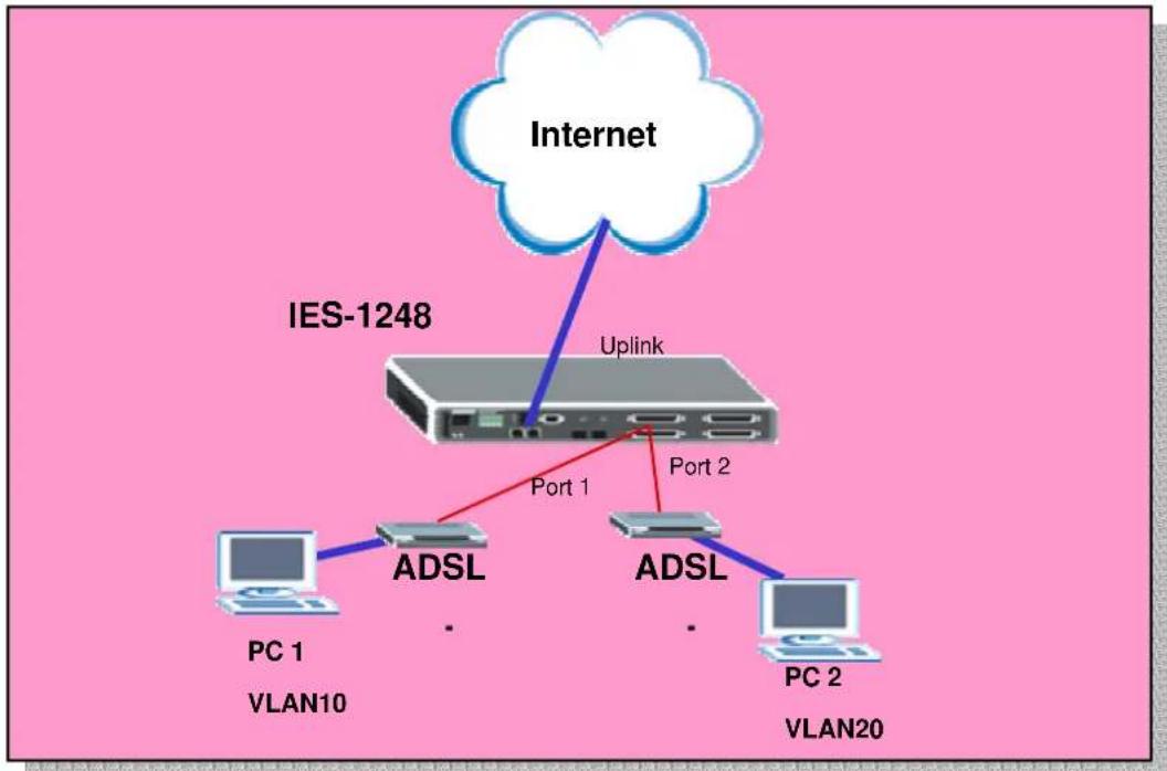
A VLAN (Virtual Area Network) allows a physical network to be partitioned into multiple logical networks. Stations on a logical network belong to one group called VLAN group. A station can belong to more than one group. The stations on the same VLAN group can communicate with each other. With VLAN, a station cannot directly talk to or hear from stations that are not in the same VLAN groups. We want to deploy VALN environment in this application. The following figure shows the VLAN example. Two PCs connect to the port 1 and port 2 of the line card
and belong to different VLAN. One is VLAN 10 and the other is VLAN 20. So they can't communication with each other. But both PC 1 and PC 2 can connect to Internet.
flowchart
graph TD
    A["Internet"] -->|Uplink| B["IES-1248"]
    B -->|Port 1| C["PC 1 VLAN10"]
    B -->|Port 2| D["PC 2 VLAN20"]
    B -->|Port 1| E["ADSL"]
    B -->|Port 2| F["ADSL"]
How to set up a VLAN environment.
In this application, we need to configure IES1-1248 and ADSL CPE. We use ZyXEL Prestige 660R-61 CPE here. Because the two ports belong to different VLAN want to go to the Internet via Uplink port of IES1248, we need to set up an extra VLAN and let the two ports be members of this VLAN.
1. IES-1248 Settings
1.1 VLAN settings
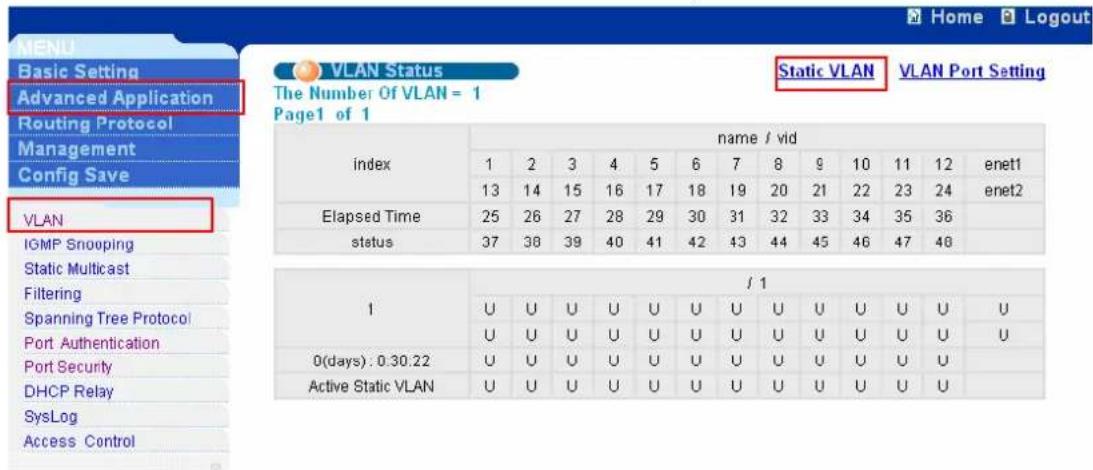
Click Advanced Application, VLAN in the navigation panel to display configuration screen as shown. Click Static VLAN to set the VLAN parameters.
text_image
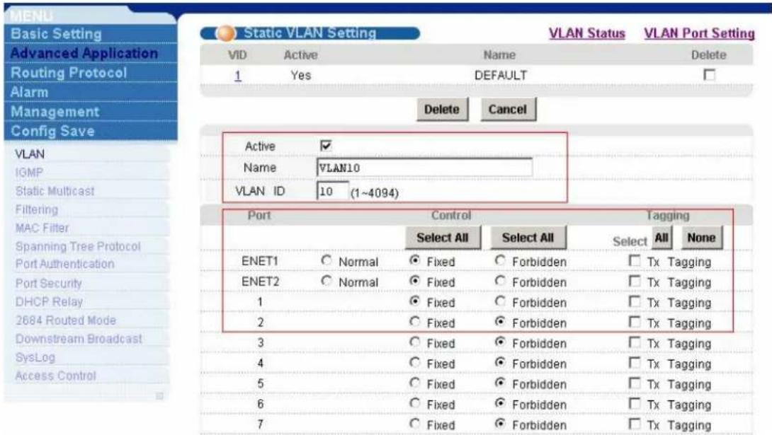
MENU Basic Setting Advanced Application Routing Protocol Management Config Save VLAN Status The Number Of VLAN = 1 Page1 of 1 Static VLAN VLAN Port Setting index name / vid 1 2 3 4 5 6 7 8 9 10 11 12=enet1 13 14 15 16 17 18 19 20 21 22 23 24=enet2 Elapsed Time 25 26 27 28 29 30 31 32 33 34 35 36 status 37 38 39 40 41 42 43 44 45 46 47 48 / 1 1 U U U U U U U U U U U U/U U/U/U/U/U/U U U/U/U/U/U/U/U/U/U/U/U/U/U/U/U/U 0(days) : 0.30.22 U/U/U/U/U/U/U/U/U/U/U/U/U/U/U/U Active Static VLAN U/U/U/U/U/U/U/U/U/U/U/U/U/U/U/UAdd VLAN10. Assign Port 1, ENET1 and ENET2 to be members of VLAN10 as shown.
text_image
MENU Basic Setting Advanced Application Routing Protocol Alarm Management Config Save VLAN IGMP Static Multicast Filtering MAC Filter Spanning Tree Protocol Port Authentication Port Security DHCP Relay 2684 Routed Mode Downstream Broadcast SysLog Access Control Static VLAN Setting VLAN Status VLAN Port Setting VID Active Name Delete 1 Yes DEFAULT Delete Cancel Active ✓ Name VLAN10 VLAN ID 10 (1~4094) Port Control Waying Select All Select All Select All None ENET1 Normal Fixed Forbidden Tx Tagging ENET2 Normal Fixed Forbidden Tx Tagging 1 Fixed Forbidden Tx Tagging 2 Fixed Forbidden Tx Tagging 3 Fixed Forbidden Tx Tagging 4 Fixed Forbidden Tx Tagging 5 Fixed Forbidden Tx Tagging 6 Fixed Forbidden Tx Tagging 7 Fixed Forbidden Tx TaggingAdd VLAN20. Assign Port 2, ENET1 and ENET2 to be members of VLAN20 as shown.

text_image
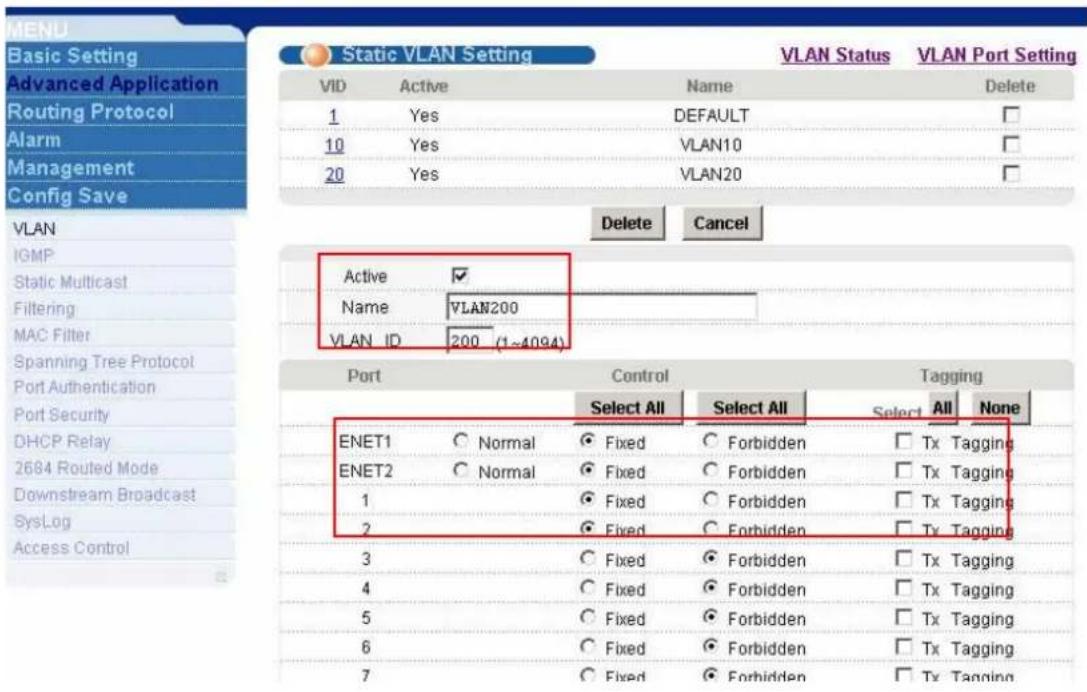
MENU Basic Setting Advanced Application Routing Protocol Alarm Management Config Save VLAN IGMP Static Multicast Filtering MAC Filter Spanning Tree Protocol Port Authentication Port Security DHCP Relay 2684 Routed Mode Downstream Broadcast SysLog Access Control Static VLAN Setting VLAN Status VLAN Port Setting VID Active Name Delete 1 Yes DEFAULT 10 Yes VLAN10 Delete Cancel Active ✓ Name VLAN20 VLAN ID 20 (1~4094) Port Control Waying Select All Select All Select All None ENET1 ○ Normal ● Fixed ○ Forbidden □ Tx Tagging ENET2 ○ Normal ● Fixed ○ Forbidden □ Tx Tagging 1 ○ Fixed ○ Forbidden □ Tx Tagging 2 ○ Fixed ○ Forbidden □ Tx Tagging 3 ○ Fixed ○ Forbidden □ Tx Tagging 4 ○ Fixed ○ Forbidden □ Tx Tagging 5 ○ Fixed ○ Forbidden □ Tx Tagging 6 ○ Fixed ○ Forbidden □ Tx Tagging 7 ○ Fixed ○ Forbidden □ Tx Tagging 8 ○ Fixed ○ Forbidden □ Tx TaggingAdd VLAN200. Assign Port 1, Port2, ENET1 and ENET2 to be members of VLAN200 as shown.
text_image
MENU Basic Setting Advanced Application Routing Protocol Alarm Management Config Save VLAN IGMP Static Multicast Filtering MAC Filter Spanning Tree Protocol Port Authentication Port Security DHCP Relay 2684 Routed Mode Downstream Broadcast SysLog Access Control Static VLAN Setting VLAN Status VLAN Port Setting VID Active Name Delete 1 Yes DEFAULT 10 Yes VLAN10 □ 20 Yes VLAN20 □ Delete Cancel Active ✓ Name VLAN200 VLAN ID 200 (1~4094) Port Control Waying Select All Select All Select All None ENET1 C Normal ● Fixed C Forbidden □ Tx Tagging ENET2 C Normal ● Fixed C Forbidden □ Tx Tagging 1 ● Fixed C Forbidden □ Tx Tagging 2 ● Fixed C Forbidden □ Tx Tagging 3 C Fixed C Forbidden □ Tx Tagging 4 C Fixed C Forbidden □ Tx Tagging 5 C Fixed C Forbidden □ Tx Tagging 6 C Fixed C Forbidden □ Tx Tagging 7 C Fixed C Forbidden □ Tx Tagging1.2 PVID settings
After set up the three VLAN, we can see Vlan10, Vlan20 and Vlan200 as shown. Now, click VLAN Port Setting to set the PVID.

text_image
MENU Basic Setting Advanced Application Routing Protocol Alarm Management Config Save VLAN IGMP Static Multicast Filtering MAC Filter Spanning Tree Protocol Port Authentication Port Security Static VLAN Setting VLAN Status VLAN Port Setting VID Active Name Delete 1 Yes DEFAULT 10 Yes VLAN10 20 Yes VLAN20 200 Yes VLAN200 Delete Cancel Active Name VLAN ID 0 (1~4094) Port Control TaggingWe assign VLAN 200(PVID) to ENET1, ENET2. Also, we assign VLAN 10 and VLAN 20 to Port1 and port2, respectively as shown.
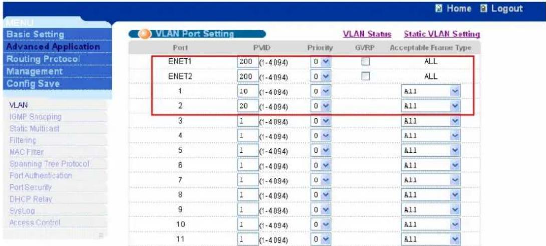
text_image
MENU Basic Setting Advanced Application Routing Protocol Management Config Save VLAN Port Setting VLAN Status Static VLAN Setting Port PVD Priority GVRP Acceptable Frame Type ENET1 200 (1-4094) 0 ▼ ALL ENET2 200 (1-4094) 0 ▼ ALL 1 10 (1-4094) 0 ▼ A11 2 20 (1-4094) 0 ▼ A11 3 1 (1-4094) 0 ▼ A11 4 1 (1-4094) 0 ▼ A11 5 1 (1-4094) 0 ▼ A11 6 1 (1-4094) 0 ▼ A11 7 1 (1-4094) 0 ▼ A11 8 1 (1-4094) 0 ▼ A11 9 1 (1-4094) 0 ▼ A11 10 1 (1-4094) 0 ▼ A11 11 1 (1-4094) 0 ▼ A111.3 Port Isolation
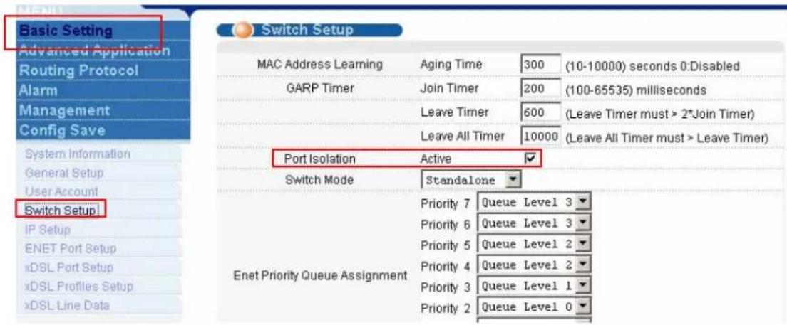
If we just want to isolate ports of IES-1248 and don't want to set any VLAN, there is another easy way to do this. Click Basic setting, Switch Setup in navigation panel to display configuration screen as shown. Check Port isolation Active check box.
text_image
MENU Basic Setting Advanced Application Routing Protocol Alarm Management Config Save System Information General Setup User Account Switch Setup! IP Setup ENET Port Setup xDSL Port Setup xDSL Profiles Setup xDSL Line Data Switch Setup MAC Address Learning Aging Time 300 (10-10000) seconds 0:Disabled GARP Timer Join Timer 200 (100-65535) milliseconds Leave Timer 600 (Leave Timer must > 2*Join Timer) Leave All Timer 10000 (Leave All Timer must > Leave Timer) Port Isolation Active ✓ Switch Mode Standalone Enet Priority Queue Assignment Priority 7 Queue Level 3 Priority 6 Queue Level 3 Priority 5 Queue Level 2 Priority 4 Queue Level 2 Priority 3 Queue Level 1 Priority 2 Queue Level 02. Prestige 660R-61 Settings
Please refer to the procedures in previous application.
Triple play Application
The IES-1248 allows you to use different channels(also called Permanent Virtual Circuits or PVCs) for different services. Define channels on each DSL port for different services and assign each channel a priority, a VLAN and ATM Quality of Service (QoS). The ATM QoS allows you to regulate the average rate and fluctuations of data transmission. This helps eliminate congestion to allow transmission of real time data (such as audio and video).
In this application, we demonstrate how to set up the multiple PVCs environment. From the figure below, the PC wants to access the two kinds of network services. One is the Internet service (data service) and the other is Video service. Because we hope we can see the video smoothly, we need to set the video service higher priority. In IES-1248, we can set the two services with different VLANs and assign the PVCs with different VLAN, priority and ATM QoS. That will make the video traffic get the higher priority than data traffic. We also can expand this application to triple play environment.

flowchart
graph TD
    A["IES-1248"] -->|DSL Port 1| B["Switch"]
    B -->|PVID=20| C["Internet Access"]
    B -->|PVID=10| D["Video Server VLAN 10"]
    B -->|PVID=10| E["CPE"]
    A -->|0/33 1/34| F["Computer"]
    style A fill:#f9f,stroke:#333
    style B fill:#ccf,stroke:#333
    style C fill:#cfc,stroke:#333
    style D fill:#fcc,stroke:#333
    style E fill:#cff,stroke:#333
    style F fill:#ffc,stroke:#333
How to set up a Multiple PVCs environment.
Following procedures will introduce the settings of IES-1248, VLAN-aware switch and ADSL CPE. We use ZyXEL ES-2024 and Prestige 660R-61 as VLAN-aware switch and ADSL CPE, respectively.
1. IES-1248 Settings
1.1 VLAN setup
We can set up VLAN like procedure described in VLAN application. Add VLAN10. Assign Port 1, ENET1 to be members of VLAN10 as show. We need to check the Tx Tagging on ENET1.
Add VLAN20. Assign Port 1, ENET1 to be members of VLAN20 as show. We need to check the Tx Tagging on ENET1.
1.2 VC profile setup
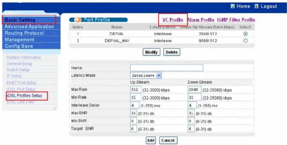
Click Basic Setting and xDSL Profile Setup in navigation panel to display the configuration screen as shown. Click VC profiles in this screen.
text_image
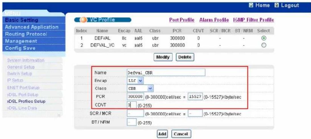
Basic Setting Advanced Application Routing Protocol Management Config Save System information General Setup Switch Setup IP Setup ENET Port Setup xDSL Port Setup xDSL Profiles Setup xDSL Line Data Port Profile VC Profile Alarm Profile IGMP Filter Profile Index Name Latency Mode Down/ Up Stream Rate( kbps) Select 1 DEFVAL Interleave 2048/512 2 DEFVAL_MAX Interleave 9088/512 Modify Delete Name Latency Mode InterLeave Up Stream Down Stream Max Rate 512 (32-3000) kbps 2048 (32-25000) kbps Min Rate 32 (32-3000) kbps 32 (32-25000) kbps Interleave Delay 4 (1-255) ms 4 (1-255) ms Max SNR 31 (0-31) db 31 (0-31) db Min SNR 0 (0-31) db 0 (0-31) db Target SNR 6 (0-31) db 6 (0-31) db Add CancelAdd Defval_CBR VC profile. Set up Encap, Class, PCR and CDVT as shown. Encap should be LLC the same as IES-1248. Class should be CBR which has higher priority in ATM QoS.
text_image
Home Logout Basic Setting Advanced Application Routing Protocol Management Config Save VC Profile Port Profile Alarm Profile IGMP Filter Profile Index Name Encap AAL Class PCR CDVT SCR / MCR BT / NRM Select 1 DEFVAL llc aa15 ubr 300000 0 - - + 2 DEFVAL_VC vc aa15 ubr 300000 0 - - + Modify Delete System Information General Setup Switch Setup IP Setup ENET Port Setup xDSL Port Setup xDSL Profiles Setup xDSL Line Data Name Defval_CBR Encap LLC Class CBR PCR 300000 (0-300000)cell/sec = 15527 (0-15527)/byte/sec CDVT 0 (0-255) SCR / MCR - (0-300000)cell/sec = - (0-15527)/byte/sec BT / NRM - (0-255) Add Cancel1.3 Multiple PVCs setup
Click Basic Setting and xDSL Port Setup in navigation panel to display the configuration screen as shown. Click VC Setup in this screen.
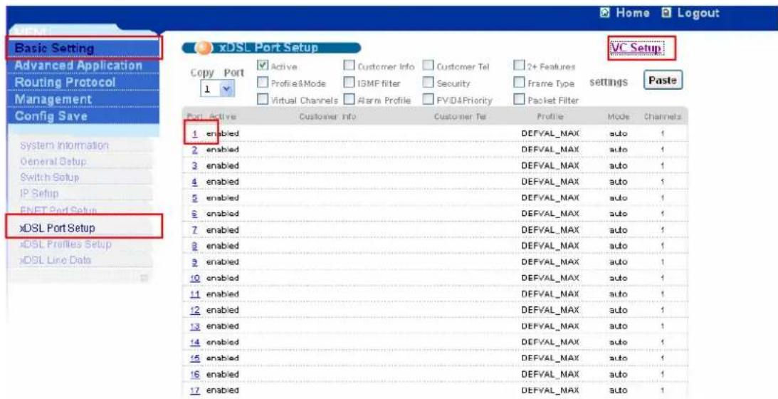
text_image
Basic Setting Advanced Application Routing Protocol Management Config Save xDSL Port Setup Copy Port 1 Active Customer Info Customer Tel 2+ Features Profile&Mode ISMF filter Security Frame Type Virtual Channels Alarm Profile FV/D&Priority Packet Filter Port Active Customer info Customer Tel Profile Mode Channels 1 enabled DEFVAL_MAX auto 1 2 enabled DEFVAL_MAX auto 1 3 enabled DEFVAL_MAX auto 1 4 enabled DEFVAL_MAX auto 1 5 enabled DEFVAL_MAX auto 1 6 enabled DEFVAL_MAX auto 1 7 enabled DEFVAL_MAX auto 1 8 enabled DEFVAL_MAX auto 1 9 enabled DEFVAL_MAX auto 1 10 enabled DEFVAL_MAX auto 1 11 enabled DEFVAL_MAX auto 1 12 enabled DEFVAL_MAX auto 1 13 enabled DEFVAL_MAX auto 1 14 enabled DEFVAL_MAX auto 1 15 enabled DEFVAL_MAX auto 1 16 enabled DEFVAL_MAX auto 1 17 enabled DEFVAL_MAX auto 1We hope VPI/VCI with 0/33 get the higher priority. We should modify this VPI/VCI with Defval_CBR profile which we created before. Press Apply button to make it take effect.
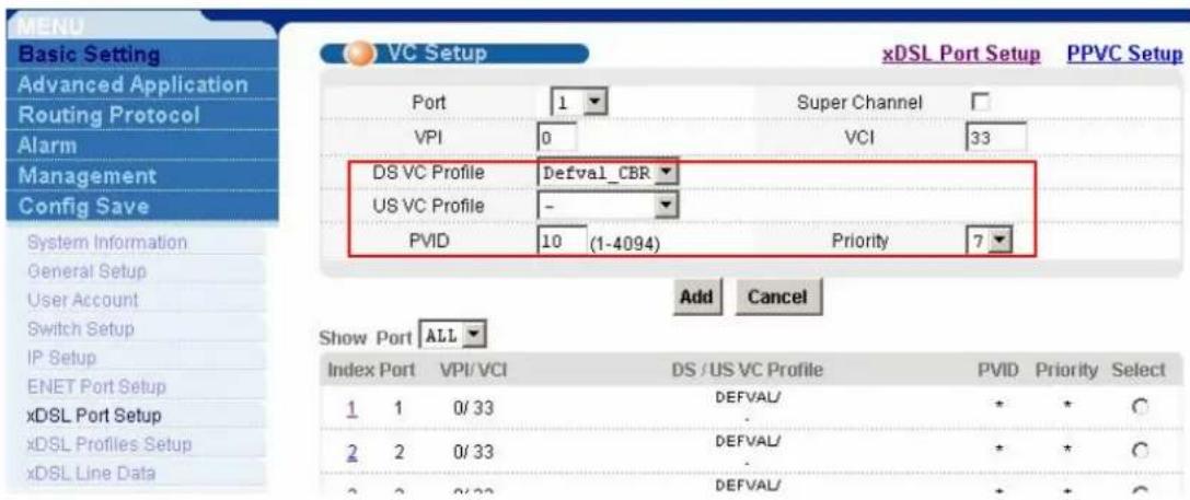
text_image
MENU Basic Setting Advanced Application Routing Protocol Alarm Management Config Save System Information General Setup User Account Switch Setup IP Setup ENET Port Setup xDSL Port Setup xDSL Profiles Setup xDSL Line Data VC Setup xDSL Port Setup PPVC Setup Port 1 Super Channel VPI 0 VCI 33 DS VC Profile Defval_CBR US VC Profile - PVID 10 (1-4094) Priority 7 Add Cancel Show Port ALL Index Port VPI/VCI DS /US VC Profile PVID Priority Select 1 1 0/ 33 DEFVAL/ . 2 2 0/ 33 DEFVAL/ . 2 2 0/ 33 DEFVAL/ . * + * * + * * + * * + *Then we add the VPI/VCI with 0/34. We apply the DEFVAL profile to this channel.
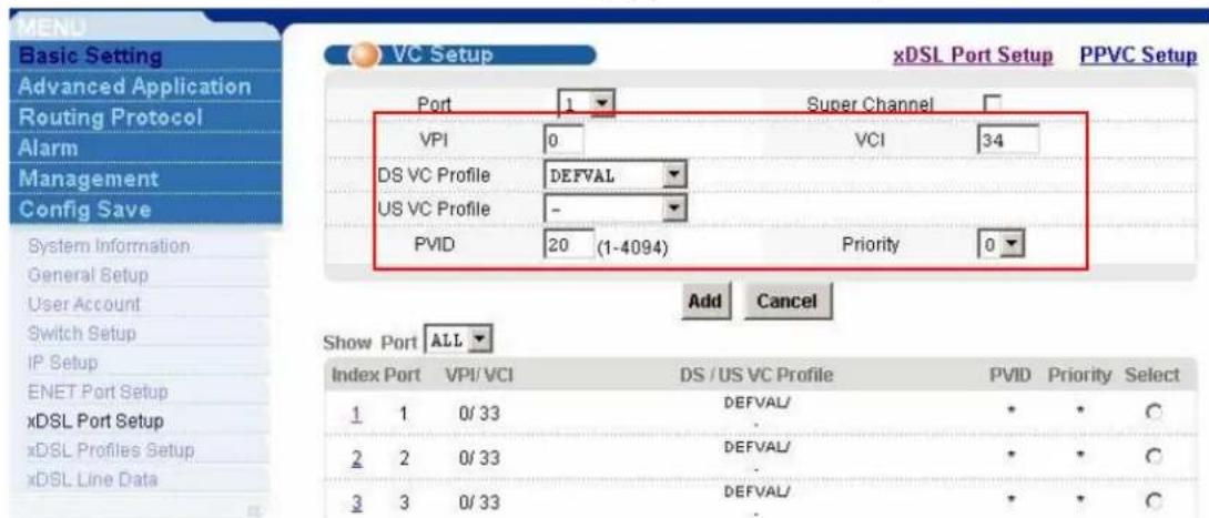
text_image
MEND Basic Setting Advanced Application Routing Protocol Alarm Management Config Save System Information General Setup User Account Switch Setup IP Setup ENET Port Setup xDSL Port Setup xDSL Profiles Setup xDSL Line Data VC Setup xDSL Port Setup PPVC Setup Port 1 Super Channel VPI 0 VCI 34 DS VC Profile DEFVAL US VC Profile - PVID 20 (1-4094) Priority 0 Add Cancel Show Port ALL Index Port VPI/ VCI DS / US VC Profile PVID Priority Select 1 1 0/ 33 DEFVAL/ * * C 2 2 0/ 33 DEFVAL/ * * C 3 3 0/ 33 DEFVAL/ * * C2. Prestige 660R-61 Settings
We need to set two channels. One is 0/33 and the other is 0/34. From former
application, we already knew how to set up CPE with one channel (0/33). We just demonstrate how to set up second channel.
2.1 Menu11.1: Remote Node Profile
In menu11.1, we should activate this profile with “Active= Yes”. The Encapsulation and the Multiplexing are the same as the menu 4. Setting “Edit ATM Options=Yes” will enter Menu 11.6.

text_image
Menu 11.1 - Remote Node Profile Rem Node Name= 2 Active= Yes Route= None Bridge= Yes Encapsulation= RFC 1483 Multiplexing= LLC-based Service Name= N/A Incoming: Rem Login= N/A Rem Password= N/A Outgoing: My Login= N/A My Password= N/A Authen= N/A Edit IP/Bridge= No Edit ATM Options= Yes Telco Option: Allocated Budget(min)= N/A Period(hr)= N/A Schedule Sets= N/A Nailed-Up Connection= N/A Session Options: Edit Filter Sets= No Idle Timeout(sec)= N/A Press ENTER to Confirm or ESC to Cancel:2.2 Menu11.6: Remote Node ATM Layer Options
We should set up another VPI/VCI with 0/34 the same as the IES-1248.
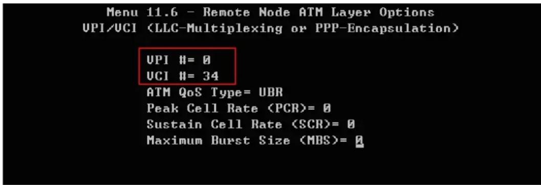
text_image
Menu 11.6 - Remote Node ATM Layer Options UPI/UCI (LLC-Multiplexing or PPP-Encapsulation) UPI #= 0 UCI #= 34 ATM QoS Type= UBR Peak Cell Rate (PCR)= 0 Sustain Cell Rate (SCR)= 0 Maximum Burst Size (MBS)= 03. ES-2024 settings
3.1 VALN
Click Advanced Application and VLAN in navigation panel to display configuration screen as shown. Click Static VLAN to show VLAN setup screen.
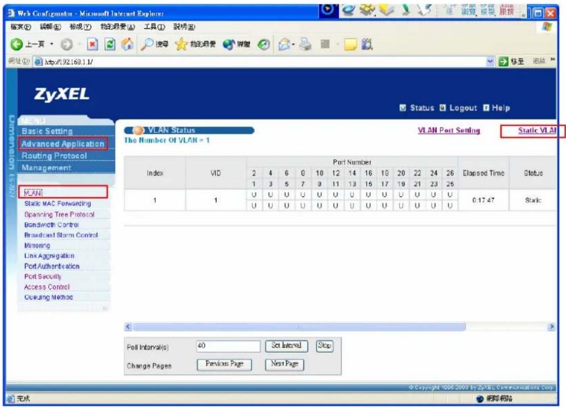
text_image
Web Configurator - Microsoft Internet Explorer 输入(E) 编辑(E) 标记(Y) 物的摘要(A) 工具(T) 説明(M) 上一页 搜索 我的摘要 媒体 网址(D) http://92.169.1.1/ 移至 连续 ZyXEL Status Logout Help VLAN Status The Number Of VLAN = 1 VLAN Post Setting Static VLAN Index VID Port Number Elapsed Time Status 2 4 6 8 10 12 14 16 18 20 22 24 26 1 3 5 7 9 11 13 15 17 19 21 23 25 1 U U U U U U U U U U U U U U U U U U U U U U U U U U U U U U U U U U U U U U 1 1 U U U U U U U U U U U U U U U U U U U U U U U U U U U U U U U U U 0:17:47 Static Poll Interval(s) 40 Set Interval Stop Change Pages Previous Page Next Page 完成 网络网络Add VLAN10. Assign Port 1, Port 10 to be members of VLAN10 as show. We need to check the Tx Tagging on Port 10.
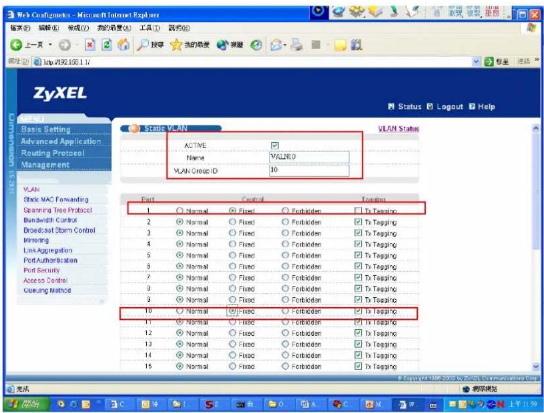
text_image
Web Configometer - Microsoft Internet Explorer 输入(E) 编辑(E) 常规(V) 我的最爱(A) 工具(T) 說明(R) 上一页 搜索 我的最爱 网络 网址 http://192.166.1.1/ ZyXEL Status Logout Help Basic Setting Advanced Application Routing Protocol Management Static VLAN VLAN Status ACTIVE ✓ Name VALNIO VLAN Group ID 10 VLAN Static MAC Forwarding Spanning Tree Protocol Bandwidth Control Broadcast Storm Control Mirroring Link Aggregation Port Authentication Port Security Access Control Cueuing Method Port Control Togeting 1 Normal Fixed Forbidden Tx Tagging 2 Normal Fixed Forbidden Tx Tagging 3 Normal Fixed Forbidden Tx Tagging 4 Normal Fixed Forbidden Tx Tagging 5 Normal Fixed Forbidden Tx Tagging 6 Normal Fixed Forbidden Tx Tagging 7 Normal Fixed Forbidden Tx Tagging 8 Normal Fixed Forbidden Tx Tagging 9 Normal Fixed Forbidden Tx Tagging 10 Normal Fixed Forbidden Tx Tagging 11 Normal Fixed Forbidden Tx Tagging 12 Normal Fixed Forbidden Tx Tagging 13 Normal Fixed Forbidden Tx Tagging 14 Normal Fixed Forbidden Tx Tagging 15 Normal Fixed Forbidden Tx Tagging 完成 源深模除Add VLAN20. Assign Port 2, Port 10 to be members of VLAN20 as show. We need to check the Tx Tagging on Port 10.
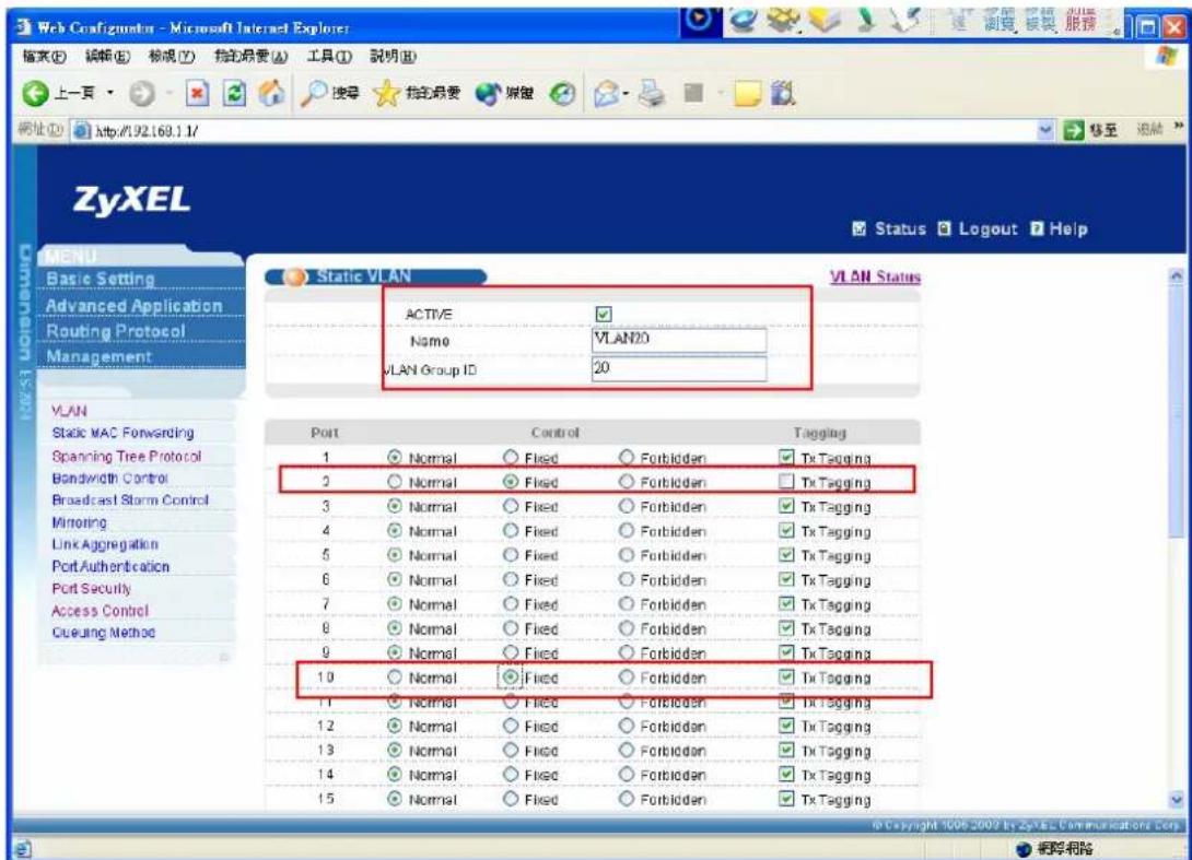
text_image
Web Configurator - Microsoft Internet Explorer 输入(E) 编辑(E) 标准(F) 拨定摘要(A) 工具(T) 說明(B) 上一页 搜索 拨定摘要 建信 地址(D) http://92.169.1.1/ Status Logout Help ZyXEL Status LOGOUT Help MENU Basic Setting Advanced Application Routing Protocol Management Static VLAN VLAN Status ACTIVE Name VLANID VLAN Group ID 20 VLAN Static MAC Forwarding Spanning Tree Protocol Bandwidth Control Broadcast Storm Control Mirroring Link Aggregation Port Authentication Port Security Access Control Cueuing Method Port Control Tagging 1 Normal Fixed Forbidden Tx Tagging 2 Normal Fixed Forbidden Tx Tagging 3 Normal Fixed Forbidden Tx Tagging 4 Normal Fixed Forbidden Tx Tagging 5 Normal Fixed Forbidden Tx Tagging 6 Normal Fixed Forbidden Tx Tagging 7 Normal Fixed Forbidden Tx Tagging 8 Normal Fixed Forbidden Tx Tagging 9 Normal Fixed Forbidden Tx Tagging 10 Normal Fixed Forbidden Tx Tagging 11 Normal Fixed Forbidden Tx Tagging 12 Normal Fixed Forbidden Tx Tagging 13 Normal Fixed Forbidden Tx Tagging 14 Normal Fixed Forbidden Tx Tagging 15 Normal Fixed Forbidden Tx Tagging © Copyright © 2006-2009 by ZyXEL Communications Corp. © Copyright © 2006-2009 by ZyXEL Communications Corp. 帮助帮助3.2 PVID setup
Click Advanced Application and VLAN in navigation panel to display configuration screen as shown. Click VLAN Port Setting to show PVID setup screen.

text_image
Web Configurations - Microsoft Internet Explorer 檔案(E) 編輯(E) 綠視(V) 拉的最愛(A) 工具(T) 說明(R) 上一頁 http://192.168.1.1/ 地址(D) http://192.168.1.1/ ZyXEL Status Logout Help VLAN Status The Number Of VLAN = 3 VLAN Port Setting Static VLAN Index VID Port Number Elapsed Time Status 2 4 6 8 10 12 14 16 18 20 22 24 26 1 3 5 7 9 11 13 15 17 19 21 23 25 1 U U U U U U U U U U U U U U U U U U U U U U U U U U U 2 - - - - T - - - - - - - - - - - - - - - - - - - - - - - - - - - - - - - - - - - - - - - - - U - - - - - T - - - - - - - - - - - - - - - - - - - - - - - - - - - - - - - 3 20 U - - - T - - -Let 10 be the PVID of Port 1 and 20 be the PVID of Port 2.
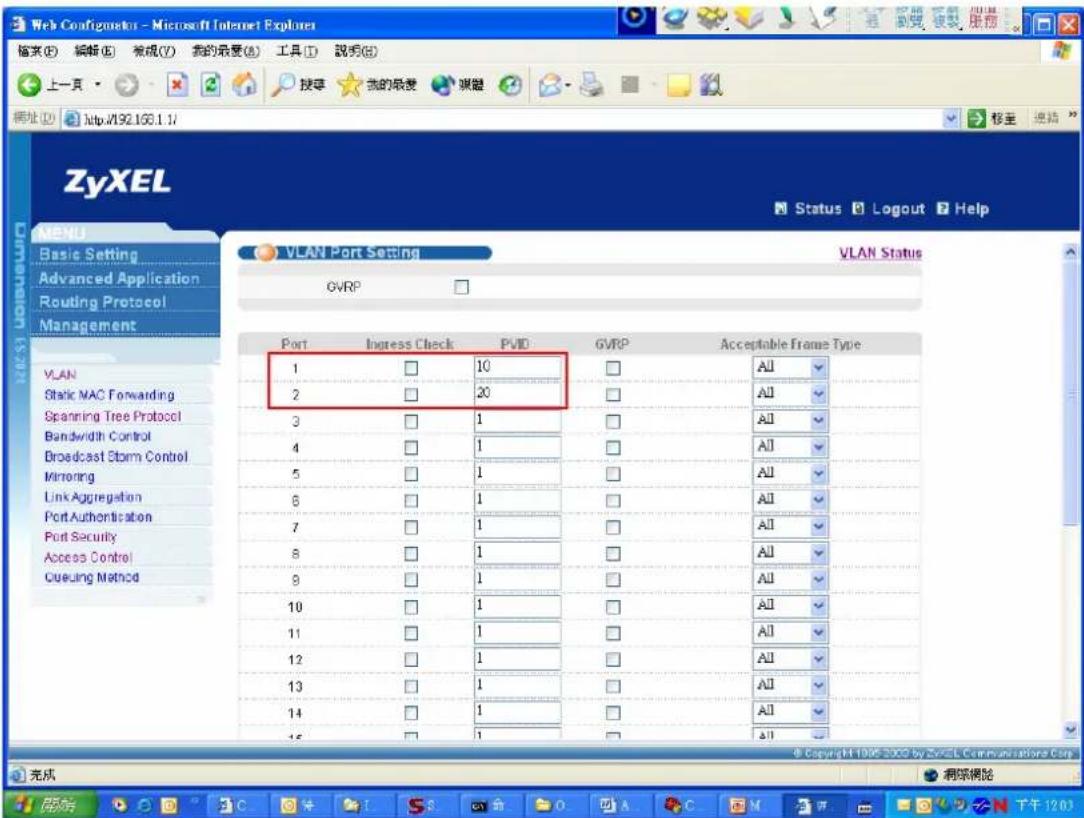
text_image
Web Configurator - Microsoft Internet Explorer 檔案(E) 編輯(E) 規成(Y) 我的最愛(B) 工具(T) 説明(R) 上一頁 按章 我的最愛 喜覽 網址(D) http://192.163.1.1/ ZyXEL Status Logout Help VLAN Port Setting VLAN Status GVRP Port Ingress Check PVID GVRP Acceptable Frame Type 1 □ 10 □ All 2 □ 20 □ All 3 □ 1 □ All 4 □ 1 □ All 5 □ 1 □ All 6 □ 1 □ All 7 □ 1 □ All 8 □ 1 □ All 9 □ 1 □ All 10 □ 1 □ All 11 □ 1 □ All 12 □ 1 □ All 13 □ 1 □ All 14 □ 1 □ All 15 □ 1 □ All 完成 網架網架 完成 下午12:03In this application, you will see the video traffic will go via 0/33 and data traffic
will go via 0/34. And the 0/33 get the higher priority. The video traffic will go first when the two traffics arrive at the same time.
802.1x Application
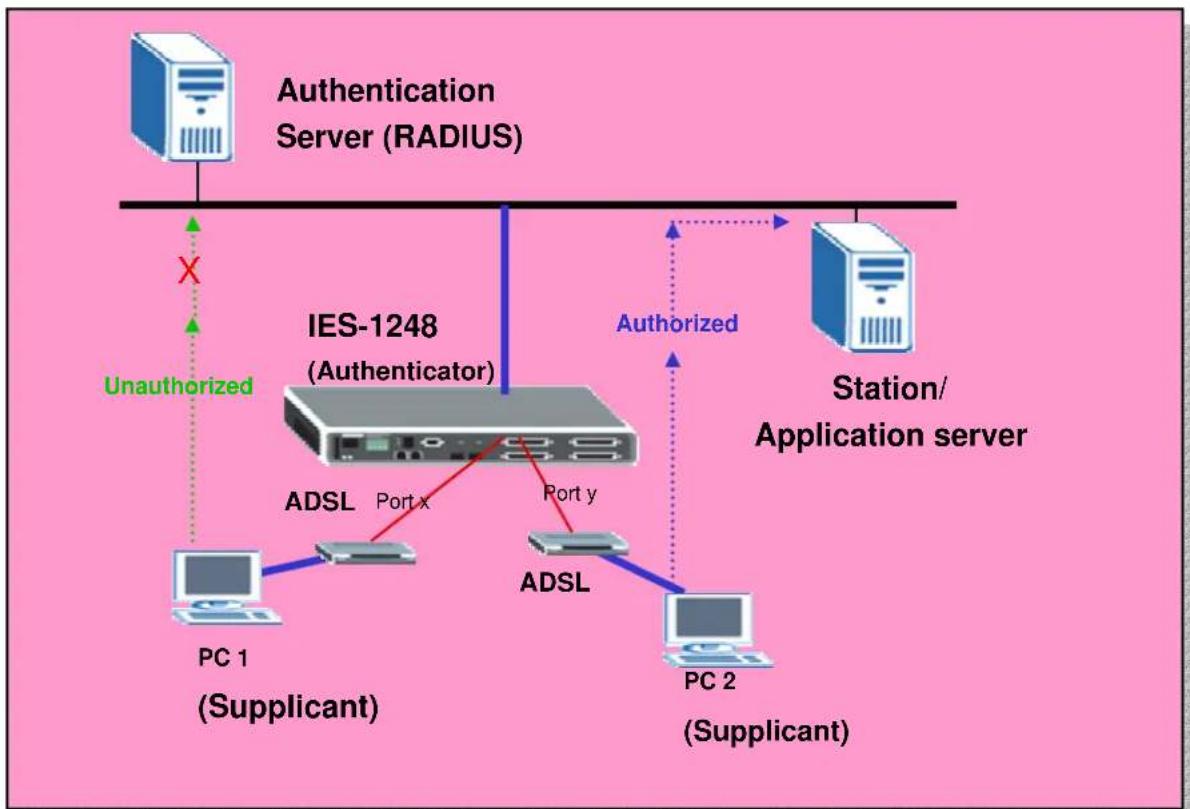
IEEE 802.1x port-based authentication is desired to prevent unauthorized ports (clients) from gaining access to the network. It is an extended authentication protocol that allows support of RADIUS (Remote Authentication Dial in User Service, RFC2138, 2139) for centralized user profile management on a network RADIUS server.
We want to deploy 802.1x environment in this application. The following figure shows the 802.1x example. PC1(supplicant) and PC2(supplicant) want to access to the application server. If PC1 is not unauthorized, the traffic from PC1 to application server will be blocked. If PC2 is an authorized client, then it can access to the application server. From the figure, IES1248 acts as an authenticator.
flowchart
graph TD
    A["Authentication Server (RADIUS)"] -->|X| B["IES-1248 (Authenticator)"]
    B -->|Unauthorized| C["PC 1 (Supplicant)"]
    B -->|Authorized| D["Station/Application server"]
    B -->|Port x Port y| E["ADSL"]
    E --> F["PC 2 (Supplicant)"]
    E --> G["ADSL"]
    G --> H["PC 1 (Supplicant)"]
How to set up an 802.1x environment.
We should configure Authenticator, RADIUS and Supplicant three parts in 802.1x
environment. The Microsoft 802.1x client and ZyXEL Vantage 50 will be used as supplication and RADIUS, respectively. Following sections will describe the detailed procedure to set up the environment.
1. IES-1248 (Authenticator) settings:
1.1 RADIUS settings:
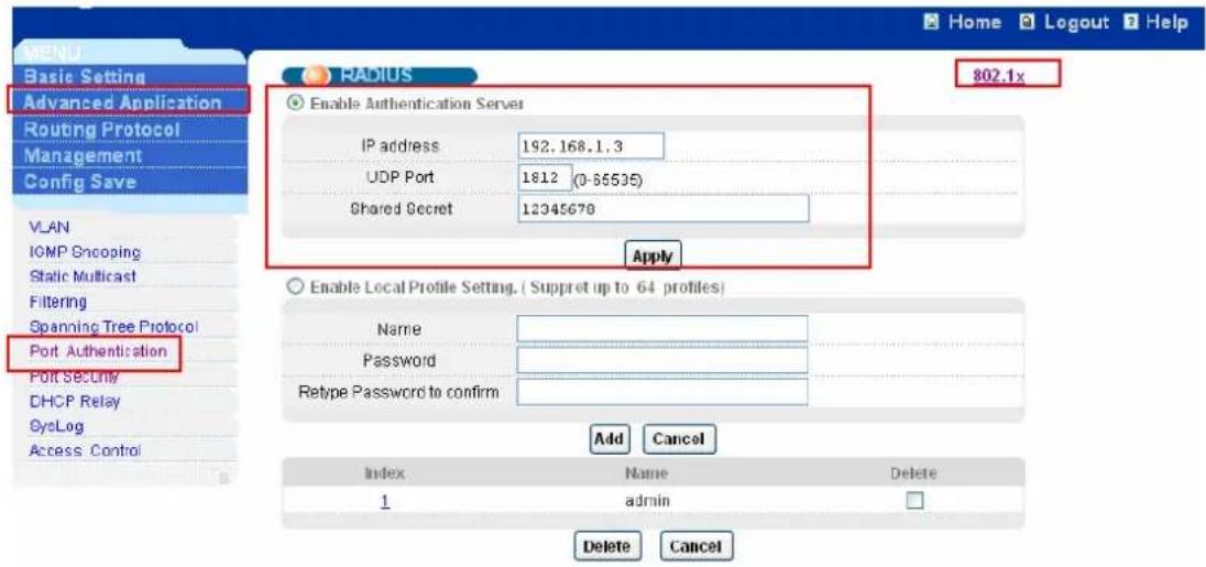
Click Advanced Application, Port Authentication in the navigation panel to display configuration screen as shown. Click Enable Authentication Server and set the RADIUS server IP address, UDP port and shared Secret, which is the same as Radius server. Then click Apply to make the settings take effect.
text_image
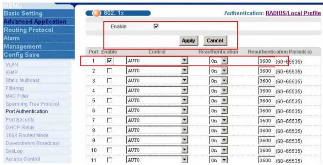
MEND Basic Setting Advanced Application Routing Protocol Management Config Save VLAN IGMP Snooping Static Multicast Filtering Spanning Tree Protocol Port Authentication Port Security DHCP Relay OscLog Access Control RADIUS 802.1x Enable Authentication Server IP address 192.168.1.3 UDP Port 1812 (0-55535) Shared Secret 12345670 Apply Enable Local Profile Setting. ( Suppret up to 64 profiles) Name Password Retype Password to confirm Add Cancel Index Name Delete 1 admin Delete CancelClick the 802.1x link to enter the 802.1x settings. Check the Enable
Authentication and click Apply button to enable 802.1x authentication. Check
Enable to turn on 802.1x authentication on that port. You can leave other settings as default values. Click Apply to save your changes.
text_image
MENU Basic Setting Advanced Application Routing Protocol Alarm Management Config Save 802.1x Authentication: RADIUS/Local Profile Enable ✓ Apply Cancel Port Enable Control Reauthentication Reauthentication Period( s) 1 ✓ AUTO 0n 3600 (60~65535) 2 □ AUTO 0n 3600 (60~65535) 3 □ AUTO 0n 3600 (60~65535) 4 □ AUTO 0n 3600 (60~65535) 5 □ AUTO 0n 3600 (60~65535) 6 □ AUTO 0n 3600 (60~65535) 7 □ AUTO 0n 3600 (60~65535) 8 □ AUTO 0n 3600 (60~65535) 9 □ AUTO 0n 3600 (60~65535) 10 □ AUTO 0n 3600 (60~65535) 11 □ AUTO 0n 3600 (60~65535)2. Vantage 50(RADIUS) settings:
We use Vantage 50 as the RADIUS server. It's a one of ZyXEL's product. Of course, you can use other RADIUS server like Funk Steel-Belted RADIUS, Cisco Access Control Server, MeetingHouse Aegis server and so on. You can configure it by WEB GUI and its default IP is 192.168.1.3.
2.1 RADIUS server setup
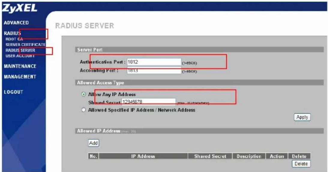
Click RADIUS, RADIUS SERVER in the navigation panel to display configuration screen as shown. You can use the default values or change the Authentication port, Shared Secret. Remember these values MUST be the as the settings of client.
text_image
ZyXEL RADIUS SERVER ADVANCED RADIUS ROOT CA SERVER CERTIFICATE RADIUS SERVER USER ACCOUNT MAINTENANCE MANAGEMENT LOGOUT Server Port Authentication Port : 1812 (1-65636) Accounting Port : 1813 (1-65626) Allowed Access Type Allow Any IP Address Shared Secret 12345678 (max. illustrated) Allowed Specified IP Address / Network Address Apply Allowed IP Address (max: 20) Add No. IP Address Shared Secret Description Action Delete Delete2.2 Create User Account
Click RADIUS, USER ACCOUNT in the navigation panel to display configuration screen as shown. You can use the existed user account or create the new one by clicking Add New User button. Remember the client site MUST use the account in RADIUS server.
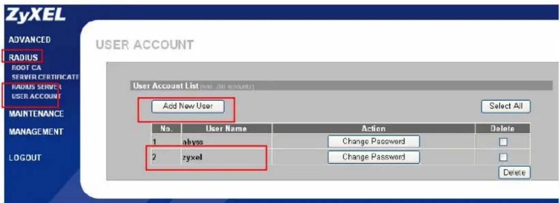
text_image
ZyXEL ADVANCED RADIUS ROOT CA SERVER CERTIFICATE RADIUS SERVER USER ACCOUNT MAINTENANCE MANAGEMENT LOGOUT USER ACCOUNT User Account List (New Account) Add New User Select All No. User Name Action Delete 1 abyss Change Password 2 zyxel Change Password Delete3. Windows XP(Supplicant) settings:
There are many supplicants we can choose like MeetingHouse Aegis client, Funk Odyssey client and Microsoft 802.1x client. We take Microsoft 802.1x client as an example here.
3.1 802.1x/MD5-challenge setup
Open the Local Area connection Properties, and then click Authentication page.
Check the Enable IEEE 802.1x authentication for this network and select the
MD5-challenge in EAP type combobox. Please see the following figure.
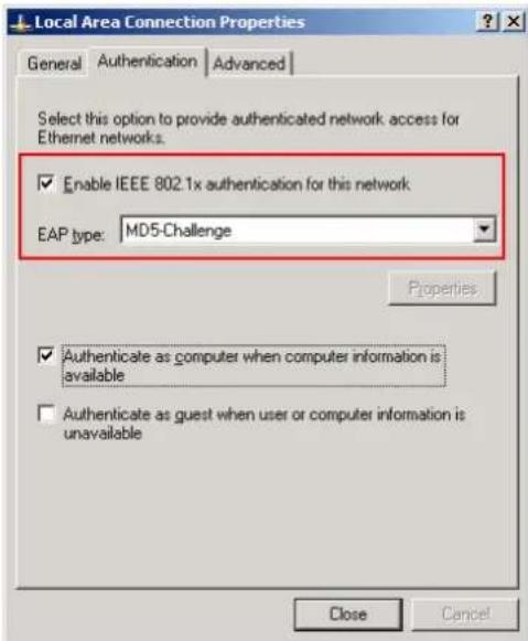
text_image
Local Area Connection Properties General Authentication Advanced Select this option to provide authenticated network access for Ethernet networks. Enable IEEE 802.1x authentication for this network EAP type: MD5-Challenge Properties Authenticate as computer when computer information is available Authenticate as guest when user or computer information is unavailable Close CancelWhen the 802.1x starts, it will prompt you to enter the user name and password. Please see the following figure.
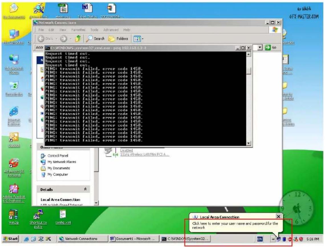
text_image
Network Connections File Edit View Favorites Tools Advanced Help Dogs Search Folders Address: C:\WINDOWS\system32\cmd.exe - ping 192.163.1.3 - t Request timed out. Request timed out. Request timed out. PING: transmit failed, error code 1458. PING: transmit failed, error code 1458. PING: transmit failed, error code 1458. PING: transmit failed, error code 1458. PING: transmit failed, error code 1458. PING: transmit failed, error code 1458. PING: transmit failed, error code 1458. PING: transmit failed, error code 1458. PING: transmit failed, error code Ping: transmit failed, error code 1458. Ping: transmit failed, error code 1458. Ping: transmit failed, error code 1458. Ping: transmit failed, error code 1458. Ping: transmit failed, error code 1458. Ping: transmit failed, error code 1458. Ping: transmit failed, error code 1458. Ping: transmit failed, error code 1458. Ping: transmit failed, error code 0 PING: transmitted failed, error code 1458. Ping: transmitted failed, error code 1458. Ping: transmitted failed, error code 1458. Ping: transmitted failed, error code 1458. Ping: transmitted failed, error code 1458. Ping: transmitted failed, error code 1458. Ping: transmitted failed, error code 1458. Ping: transmitted failed, error code 1458. Ping: transmitted failed, error code 1.0 PING: transmitted failed, error code 1.0 PING: transmitted failed, error code 1.0 PING: transmitted failed, error code 1.0 PING: transmitted failed, error code 1.0 PING: transmitted failed, error code 1.0 PING: transmitted failed, error code 1.0 PING: transmitted failed, error code 1.0 PING: transmitted failed, error code 1458. PING: transmitted failed, error code 1458. PING: transmitted failed, error code 1458. PING: transmitted failed, error code 1458. PING: transmitted failed, error code 1458. PING: transmitted failed, error code 1458. PING: transmitted failed, error code 1458. PING: transmitted failed, error code 1458. PNG: transmitted failed, error code 1458. PNG: transmitted failed, error code 1458. PNG: transmitted failed, error code 1458. PNG: transmitted failed, error code 1458. PNG: transmitted failed, error code 1458. PNG: transmitted failed, error code 1458. PNG: transmitted failed, error code 1458. PNG: transmission failed, error code 1458. PNG: transmission failed, error code 1458. PNG: transmission failed, error code 1458. PNG: transmission failed, error code 1458. PNG: transmission failed, error code 1458. PNG: transmission failed, error code 1458. PNG: transmission failed, error code 1458. PNG: transmission failed, Error Code Disabled 11c/a Wireless LAN Mini PCI A... Control Panel My Network Flaces My Documents My Computer Details Local Area Connection WinUp Shootout to putty console.xml Local Area Connection Click here to enter your user name and password for the network Start Western Connectors Document1 - Microsoft C:\WINDOWS\system32... EN 5:26 PMAfter click the icon, there will be a dialog for entering the user name and password. Click ok after input the correct user name and password that are in the database of authentication server. The settings of client site are finished.
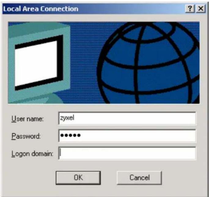
text_image
Local Area Connection User name: zyxel Password: •••••• Logon domain: OK CancelAfter above procedure, we can allow the authenticated port the access the server. If the DSL port doesn't be authenticated, the PCs behind the port can't access the network.
4. Prestige 660R-61 Settings
Please refer to the procedures in previous application.
Setting up the Syslog Server
ZyXEL products are able to send system log to a Syslog deamon such as Unix Syslogd and Kiwi's Syslog Daemon (http://www.kiwisyslog.com/). When DSL or Ethernet ports are linked up/down, IES-1248 sends a record to Syslog server. The Syslog server can be placed on the network, which IES-1248 can access.
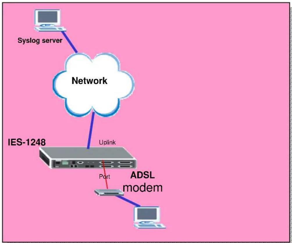
flowchart
graph TD
    A["Syslog server"] --> B["Network"]
    B --> C["IES-1248"]
    C --> D["Uplink"]
    D --> E["Port"]
    E --> F["ADSL modem"]
    F --> G["Computer"]
How to set up a Syslog server.
We should configure IES-1248 and Syslog server in this application. Here, we use the Kiwi's Syslog Daemon as an example. Following sections will describe the detailed procedures to set up the environment.
1. Install and Run Kiwi's Syslog Server
Double Click the Kiwi's Syslog Server installing program. It is very easy to install it.

After finishing the installation, you can run it from the Start Menu. And you will see following dialog. And the Server's IP is 192.168.1.77.

text_image
Kint Syslog Daemon (version 7.0.3) File View Help Display DO (Default) Date Time Priority Hostname Message 100% 0 MPH 10:56 02-17-20052. IES-1248 settings
Click Advanced Application, SysLog in the navigation panel to display configuration screen as shown. Check the Enable UNIX Syslog. Assign the UNIX Syslog Server IP, 192.168.1.77 in this case. Then press the Apply button and the setup is complete.

text_image
MENU Basic Setting Advanced Application Routing Protocol Alarm Management Config Save VLAN IGMP Static Multicast Filtering MAC Filter Spanning Tree Protocol Port Authentication Port Security DHCP Relay 2684 Routed Mode Downstream Broadcast SysLog Access Control SysLog Enable UNIX Syslog SysLog Server IP 192.168.1.77 Apply CancelWhen DSL ports are linked up/down, IES-1248 sends a record to Syslog server. We can see these logs in Kiwi's Syslog server.

text_image
Kawi Xyclog Daemon (version 7.0.3) File View Help Display 00 [Default] Date Time Priority Hostname Messoc 02-17-2005 11:24:51 Locall.AAlert 192.168.1.1 Jan 1 00:05:36 BAS INFO ADSL Link Info: NM:31/30(dB)! 02-17-2005 11:24:51 Locall.AAlert 192.168.1.1 Jan 1 00:05:36 BAS INFO ADSL Link Up[SN-2]: 9087/511! 02-17-2005 11:24:21 Locall.AAlert 192.168.1.1 Jan 1 00:05:06 BAS WARN ADSL Link Down[SN-1]! 02-17-2005 11:23:55 Locall.AAlert 192.168.1.1 Jan 1 00:04:40 BAS INFO Session Begin! 100% 4 MPH 11:27 02-17 2005Setting up the Ring Environment
The Ring topology is used to guarantee the network being normal even if one link between two device broken. So, in ring topology, the network will work well if one link is broken. In Ring Topology, you must enable RSTP/STP to prevent the loop issue.
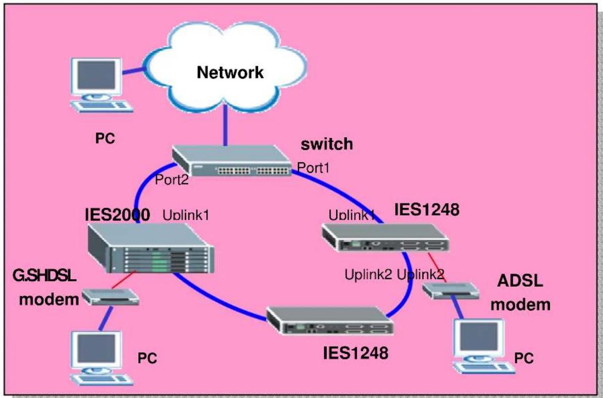
flowchart
graph TD
    A["PC"] --> B["Network"]
    B --> C["Port1"]
    C --> D["switch"]
    D --> E["Port2"]
    E --> F["IES2000 Uplink1"]
    F --> G["IP"]
    G --> H["IP"]
    H --> I["IP"]
    I --> J["IP"]
    J --> K["ADSL modem"]
    K --> L["PC"]
    M["G.SHDSL modem"] --> N["PC"]
    O["IP"] --> P["IP"]
    Q["IP"] --> R["IP"]
    S["IP"] --> T["IP"]
    U["IP"] --> V["IP"]
    W["IP"] --> X["IP"]
    Y["IP"] --> Z["IP"]
    style A fill:#f9f,stroke:#333
    style B fill:#ccf,stroke:#333
    style C fill:#cfc,stroke:#333
    style D fill:#fcc,stroke:#333
    style E fill:#cff,stroke:#333
    style F fill:#ffc,stroke:#333
    style G fill:#cfc,stroke:#333
    style H fill:#cfc,stroke:#333
    style I fill:#cfc,stroke:#333
    style J fill:#cfc,stroke:#333
    style K fill:#cfc,stroke:#333
    style L fill:#cfc,stroke:#333
    style M fill:#fcc,stroke:#333
    style N fill:#fcc,stroke:#333
    style O fill:#fcc,stroke:#333
    style P fill:#fcc,stroke:#333
    style Q fill:#fcc,stroke:#333
    style R fill:#fcc,stroke:#333
    style S fill:#fcc,stroke:#333
    style T fill:#fcc,stroke:#333
How to set up a Ring Environment.
We set up Ring environment with one IES1248, one IES2000 and one ES4024. A PC behind IES can connect the PC in the network even one of the links broken.
Following sections will describe the detailed procedures to set up the environment.
1. IES-1248 settings
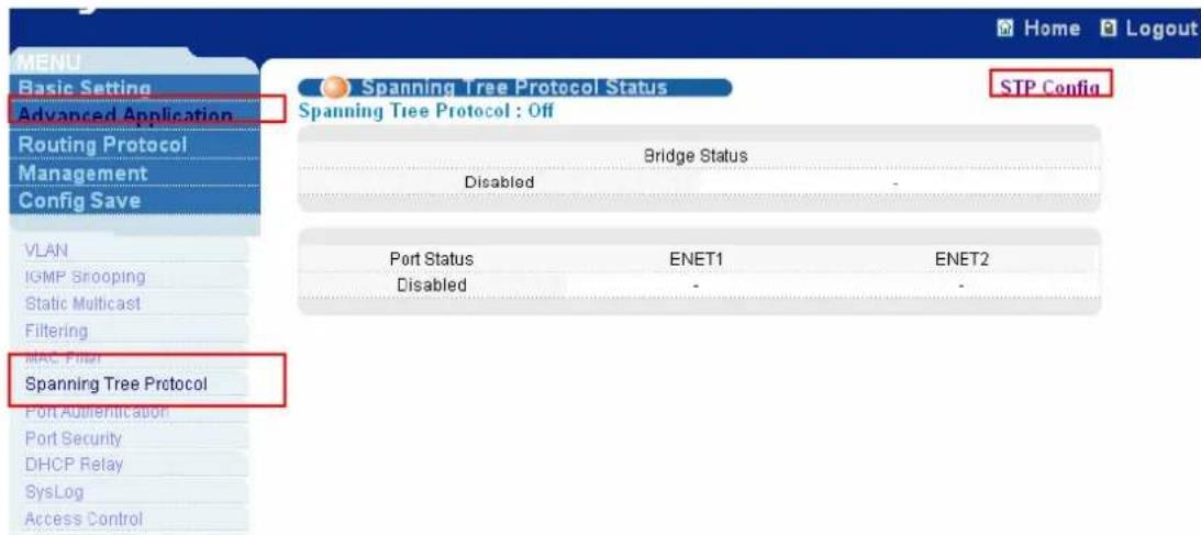
1.1 Enable Spanning Tree protocol on Ethernet ports
Click Advanced Application, Spanning Tree Protocol in the navigation panel to display configuration screen as shown. You will see the Spanning Tree Protocol
Status page. Click STP config to configure panning tree protocol settings.
text_image
MEN Basic Setting Advanced Application Routing Protocol Management Config Save VLAN IGMP Slooping Static Multicast Filtering MAC Filter Spanning Tree Protocol Port Authentication Port Security DHCP Relay SysLog Access Control Home Logout Spanning Tree Protocol Status STP Config Spanning Tree Protocol : Off Bridge Status Disabled - Port Status ENET1 ENET2 Disabled -Click Active to enable Spanning Tree Protocol. Then enable it on ENET1 port and ENET2 port.

text_image
Spanning Tree Protocol STP Status Active Bridge Priority 32768 (0-61440) Hello Time 2 (1-10) seconds MAX Age 20 (6-40) seconds Forwarding Delay 15 (4-30) seconds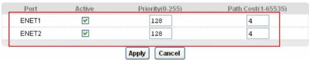
text_image
Port Active Priority(0-255) Path Cost(1-65535) ENET1 ✓ 128 4 ENET2 ✓ 128 4 Apply Cancel2. Setup IES2000
2.1 Enable Spanning Tree protocol
Click Switch Setup in the navigation panel to display configuration screen as shown. Then check Spanning Tree Protocol to enable it.

text_image
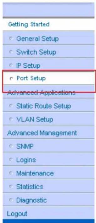
Getting Started General Setup Switch Setup IP Setup Port Setup Advanced Applications Static Route Setup VLAN Setup Advanced Management SNMP Logins Maintenance Statistics Diagnostic Logout
text_image
Priority Queue Assignment Priority Level 7 6 5 4 3 2 1 0 Queue 3 3 2 2 1 0 0 1 ✓ Rapid Spanning Tree Protocol Bridge Priority 32768 Hello Time 2 seconds MAX Age 20 seconds Forwarding Delay 15 seconds ☐ DHCP relay DHCP Server List 0.0.0.0 0.0.0.0 0.0.0.02.2 Enable Spanning Tree protocol on Ethernet ports
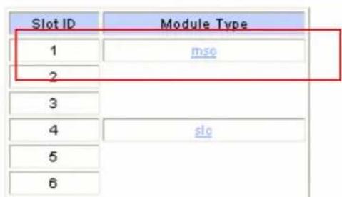
Click Port Setup in the navigation panel to display configuration screen as shown. Click msc to display MSC card Port setup.
text_image
Getting Started ○ General Setup ○ Switch Setup ○ IP Setup ○ Port Setup Advanced Applications ○ Static Route Setup ○ VLAN Setup Advanced Management ○ SNMP ○ Logins ○ Maintenance ○ Statistics ○ Diagnostic LogoutPort Setup
text_image
Slot ID Module Type 1 mso 2 3 4 slo 5 6Click Uplink2 to set up this port.
Slot 1 Port Setup
MSC 1000
Port Setup
| Port | Active | Name | Type |
| Subtending 1 | Yes | none | None |
| Subtending 2 | Yes | none | None |
| Uplink 1 | Yes | none | 1000Base I |
| Uplink 2 | Yes | none | 1000Base T |
Check Spanning Tree Protocol to enable it.
Slot 1 Edit Port Setup
MSC 1000
Up
Uplink 2
Name


Active

Uplink Mode

VLAN Trunking
Default 802.1p Priority 0
| Type | Speed | Duplex | Flow Control |
| 1000BaseT | Auto | Full |

Rapid Spanning Tree Protocol
| Priority | Path Cost |
| 128 | 4 |
Take the same procedures with Uplink1. Please see the following figure.

text_image
Slot 1 Edit Port Setup MSC 1000 Uplink 1 Name ✓ Active ✓ Uplink Mode □ VLAN Trunking Default 802.1p Priority 0 Type Speed Duplex Flow Control 1000BaseT Auto Full ✓ Rapid Spanning Tree Protocol Priority Way Cost 128 43. Setup ES4024
3.1 Enable Spanning Tree protocol on Ethernet ports
Click Advanced Application, Spanning Tree Protocol in the navigation panel to display configuration screen as shown. You will see the Spanning Tree Protocol Status page. Click Configuration to configure panning tree protocol settings.

text_image
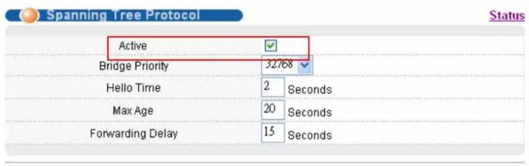
MANU Basic Setting Advanced Application Routing Protocol Management VLAN Static MAC Forwarding Filtering Spanning Tree Protocol Bandwidth Control Broadcast Storm Control Mirroring Link Aggregation Port Authentication Port Security DHCP Spanning Tree Protocol Status Configuration Spanning Tree Protocol : Down Bridge Root Our Bridge Bridge ID 0000-000000000000 0000-0000000000000 Hello Time (second) 0 0 Max Age (second) 0 0 Forwarding Delay (second) 0 0 Cost to Bridge 0 Port ID 0X0000 Topology Changed Times 0 Time Since Last Change 0:00:00Click Active to enable Spanning Tree Protocol. Then enable it on Port 1 and Port 2.
text_image
Spanning Tree Protocol Status Active Bridge Priority 32768 Hello Time 2 Seconds Max Age 20 Seconds Forwarding Delay 15 Seconds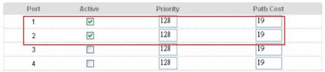
other
| Port | Active | Priority | Path Cost | |---|---|---|---| | 1 | ✓ | 128 | 19 | | 2 | ✓ | 128 | 19 | | 3 | □ | 128 | 19 | | 4 | □ | 128 | 19 |4. Results
We can see the link between port 2 of ES4024 and Uplink1 of IES2000 will be blocked as shown after we connect.
| Port | Link | State | LACP | TxPkte | RxPkte | Errors | Tx KB/s | Rx KB/s | Up Time |
| 1 | 100M/F | FORWARDING | Disabled | 1335 | 1627 | 0 | 0.0 | 0.0 | 0:07:50 |
| 2 | 100M/F | BLOCKING | Disabled | 216 | 474 | 2 | 0.0 | 0.0 | 0:07:44 |
| 3 | Down | STOP | Disabled | 0 | 0 | 0 | 0.0 | 0.0 | 0:00:00 |
| 4 | Down | STOP | Disabled | 0 | 0 | 0 | 0.0 | 0.0 | 0:00:00 |
| 5 | Down | STOP | Disabled | 0 | 0 | 0 | 0.0 | 0.0 | 0:00:00 |
| 6 | 100M/F | FORWARDING | Disabled | 2868 | 2380 | 0 | 0.0 | 0.0 | 0:07:41 |
| 7 | Down | STOP | Disabled | 0 | 0 | 0 | 0.0 | 0.0 | 0:00:00 |
| 8 | Down | STOP | Disabled | 0 | 0 | 0 | 0.0 | 0.0 | 0:00:00 |
| 9 | Down | STOP | Disabled | 0 | 0 | 0 | 0.0 | 0.0 | 0:00:00 |
| 10 | Down | STOP | Disabled | 0 | 0 | 0 | 0.0 | 0.0 | 0:00:00 |
After we remove the cable between port 1 of IES1248 and port 1 of ES4024, the connection still exists. We can remove any one of the cable. That will not affect the connection. You can see the blocking port will become forwarding port.
Status
System Up Time : 2:11:04
| Port | Link | State | LACP | TxPkts | RxPkts | Errors | Tx KB/s | Rx KB/s | Up Time |
| 1 | Down | STOP | Disabled | 0 | 0 | 0 | 0.0 | 0.0 | 0:00:00 |
| 2 | 100M/F | FORWARDING | Disabled | 217 | 683 | 2 | 0.0 | 0.0 | 0:01:44 |
| 3 | Down | STOP | Disabled | 0 | 0 | 0 | 0.0 | 0.0 | 0:00:00 |
| 4 | Down | STOP | Disabled | 0 | 0 | 0 | 0.0 | 0.0 | 0:00:00 |
| 5 | Down | STOP | Disabled | 0 | 0 | 0 | 0.0 | 0.0 | 0:00:00 |
| 6 | 100M/F | FORWARDING | Disabled | 3278 | 2698 | 0 | 0.0 | 0.0 | 0:14:32 |
| 7 | Down | STOP | Disabled | 0 | 0 | 0 | 0.0 | 0.0 | 0:00:00 |
Setting up the IGMP Snooping/IGMP Filtering
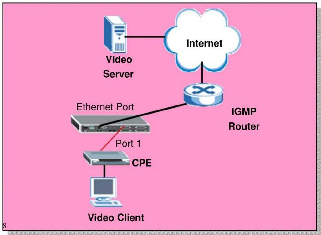
Without IGMP snooping multicast traffic is treated in the same manner as broadcast traffic, that is, it is forwarded to all port. With IGMP snooping, multicast traffic of a group is only forwarded to ports that have members of that group. IGMP snooping generates no additional network traffic, allowing you to significantly reduce multicast traffic passing through the IP-DSLAM. IGMP filtering is for allowing a port to join some specific IGMP groups. This can be applied in Video service providers. They can only open some specific channels (groups) to specific ports.
flowchart
graph TD
    A["Video Server"] --> B["Internet"]
    B --> C["IGMP Router"]
    C --> D["CPE"]
    D --> E["Video Client"]
    F["Ethernet Port"] --> D
    style A fill:#f9f,stroke:#333
    style B fill:#ccf,stroke:#333
    style C fill:#cfc,stroke:#333
    style D fill:#fcc,stroke:#333
    style E fill:#cff,stroke:#333
How to set up IGMP snooping/IGMP filtering
Here, we only set up the IES1248 to support IGMP snooping and IGMP filtering. Please refer to the user guide of the Video Server and the subscriber device. We assume the video server provides three channels, movie 1 on 240.10.10.8 group, movie 2 on 240.10.10.9 group and movie 3 on 240.10.10.10 group. And we assume the subscriber want to subscribe two channel, movie 1 and movie 2. If we don't enable the IGMP snooping, every one can see all movies. If we don't set the IGMP filtering on the port, the subscriber behind the port will receive all movies.
1. IES-1248 settings
1.1 Enable IGMP Snooping
Click IGMP setup on IGMP Snooping page and enable the IGMP snooping. After a while, you will see the number of Query will increase when IES-1248 receives the query packet from IGMP router.

text_image
MENU Basic Setting Advanced Application Routing Protocol Alarm Management Config Save VLAN IGMP Static Multicast Filtering MAC Filter Spanning Tree Protocol Port Authentication Port Security DHCP Relay 2684 Routed Mode Downstream Broadcast SysLog Access Control IGMP Setup Filter Setup Query 0 Report 0 Leave 0 Number of IGMP Groups 0 Previous Reload Next Page 0 of 0 Index VID IP Address 1 2 3 4 5 6 7 8 9 10 11 12 13 14 15 16 17 18 19 20 21 22 23 24 ENET1 25 26 27 28 29 30 31 32 33 34 35 36 37 38 39 40 41 42 43 44 45 46 47 48 ENET2
text_image
MENU Basic Setting Advanced Application Routing Protocol Alarm Management Config Save VLAN IGMP IGMP Mode Snooping IGMP Status Filter Setup ApplyMeanwhile, if the subscriber sends the join packet, we can see the number of Report will increase and the IGMP table will be created.
1.2 Set up IGMP Filtering
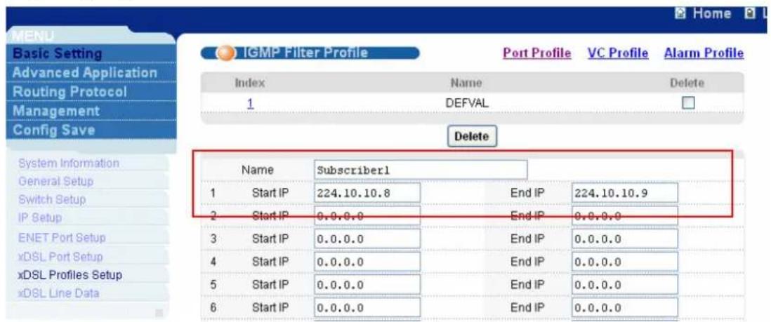
If we don't set up IGMP filtering, the subscriber will receive all the movies. We set up a IGMP filter Profile and apply it to specific port to limit the channels subscriber can see. Click Basic Setting, xDSL Profiles Setup in the navigation panel to display configuration screen as shown. And click the IGMP Filter Profile to show the setup page.

text_image
MENU Basic Setting Advanced Application Routing Protocol Management Config Save System Information General Setup Switch Setup IP Setup ENET Port Setup xDSL Port Setup xDSL Profiles Setup xDSL Line Data Port Profile VC Profile Alarm Profile IGMP Filter Profile Index Name Latency Mode Down/ Up Stream Rate( kbps) Select 1 DEFVAL Interleave 2048/ 512 2 DEFVAL_MAX Interleave 9088/ 512 Modify Delete Name Latency Mode Interleave Up Stream Down Stream Max Rate 512 (32-3000) kbps 2048 (32-25000) kbps Min Rate 32 (32-3000) kbps 32 (32-25000) kbps Interleave Delay 4 (1-255) ms 4 (1-255) msIn this case we only allow the subscriber to join movie 1 and movie 2. That means only the groups 240.10.10.8 and 240.10.10.9 can be forwarded this subscribed port.
text_image
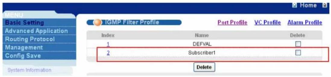
MENU Basic Setting Advanced Application Routing Protocol Management Config Save IGMP Filter Profile Port Profile VC Profile Alarm Profile Index Name Delete 1 DEFVAL Delete System Information General Setup Switch Setup IP Setup ENET Port Setup xDSL Port Setup xDSL Profiles Setup xDSL Line Data Name Subscriber1 1 Start IP 224.10.10.8 End IP 224.10.10.9 2 Start IP 0.0.0.0 End IP 0.0.0.0 3 Start IP 0.0.0.0 End IP 0.0.0.0 4 Start IP 0.0.0.0 End IP 0.0.0.0 5 Start IP 0.0.0.0 End IP 0.0.0.0 6 Start IP 0.0.0.0 End IP 0.0.0.0After create this profile, there is a new profile added in the list.
text_image
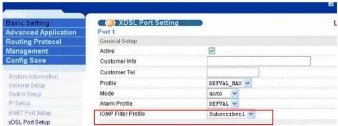
MENU Basic Setting Advanced Application Routing Protocol Management Config Save System Information IGMP Filter Profile Port Profile VC Profile Alarm Profile Index Name Delete 1 DEFVAL 2 Subscriber1 DeleteThen we need to apply the profile to port 1. Click Basic Setting, xDSL Profiles
Setup in the navigation panel to display configuration screen as shown. Click the port index 1 to set up this port.

text_image
Basic Setting Advanced Application Routing Protocol Management Config Save xDSL Port Setup Copy Port 1 Active Customer Info Customer Tel 2+ Features Profile&Mode IGMP filter Security Frame Type Virtual Channels Alarm Profile PVIO&Priority Packet Filter Port Active Customer Info Customer Tel Profile Mode Channels VC Setup settings Paste System Information General Setup Switch Setup IP Setup FNET Port Setup xDSL Port Setup xDSL Promes Setup xDSL Line DataWe select the Subscriber1 in IGMP Filter Profile Combobox. And click Apply to let the setting take effect.
text_image
MENU Basic Setting Advanced Application Routing Protocol Management Config Save System Information General Setup Switch Setup IP Setup ENET Port Setup xDSL Port Setup XDSL Port Setting Port 1 General Setup Active Customer Info Customer Tel Profile DEFVAL_MAX Mode auto Alarm Profile DEFVAL IGMP Filter Profile Subscriber1Go back to check the IGMP Snooping table. We will see only two channels allowed to be forwarded to port 1.
Static Multicast
What is Static Multicast Filter?
Static Multicast Filter allow network administrator to configure multicast group consisting of one or more ranges of MAC multicast addresses. An administrator can control multicast traffic per-switch-port basis with static multicast filter. By default, all multicast traffic are dropped without static multicast filter setup or IGMP snooping which cause some routing protocol such as RIPv2 and OSPF can not be passed through IP DSLAM. So administrator must do any configuration of static multicast filter to pass such routing protocol and other related application smoothly.
Some Well-known multicast group address:
224.0.0.1----all systems on this subnet
224.0.0.2----all routers on this subnet
224.0.0.5----all routers running OSPF
224.0.0.6----all Designed Routers running OSPF
224.0.0.9----for RIPv2
224.0.1.1----for NTP
Before using static multicast filter, you must mapping Multicast IP address to Multicast MAC address because IES IPDSLAM using Multicast MAC address to forwarding multicast traffic.
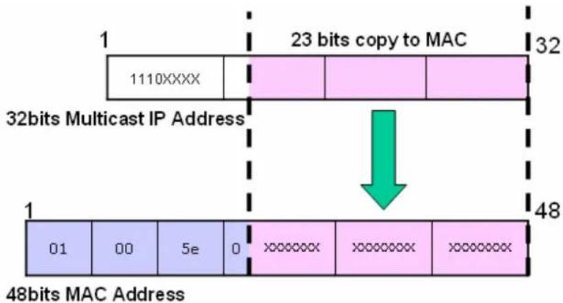
text_image
1 1110XXXX 23 bits copy to MAC 32 32bits Multicast IP Address 1 01 00 5e 0 XXXXXX XXXXXX XXXXXX 48bits MAC Address 48bits MAC Address* 32 (2 ^6 ) multicast IP addresses will map to the same multicast MAC address.
This feature can also be combined with IGMP Snooping feature to make ports know multicast traffic that are not learned by IGMP Snooping or forbid specified ports to receive multicast traffic learned by IGMP Snooping.
Application Scenario
Scenario Description

flowchart
graph TD
    A["Internet"] --> B["Static Multicast Filter"]
    B --> C["IP/TV Server"]
    C --> D["Client A\nNo channel"]
    C --> E["Client B\nChannel 1"]
    C --> F["Client C\nChannel 1\nChannel 2"]
    D --> G["Computer"]
    E --> H["Computer"]
    F --> I["Computer"]
    G --> J["Internet"]
    H --> J
    I --> J
    style A fill:#f9f,stroke:#333
    style B fill:#ccf,stroke:#333
    style C fill:#cfc,stroke:#333
An ISP wants to provide multicast video service to end user and subscribes who with different pay enjoy different programs.
Client A (connect to ADSL port 1) is a normal subscribe, so he has no authority to access movie resource.
Client B (connect to ADSL port 2) is a pay subscribe, he has authority to access limited movie resource (for example, just only channel 1).
Client C (connect to ADSL port 3) is a VIP subscribe, so he has the highest authority to access all movie resource (for example, both channel 1 and 2)
Static Multicast Filters can specify which video channels (based on multicast MAC addresses) are allowed or denied to be received by each subscribe.
The Multicast traffic MAC address of different channels as follows
IGMP Query: 01:00:5E:00:00:01 (224.0.0.1)
IGMP Report: 01:00:5E:00:00:02 (224.0.0.2)
Channel 1 multicast MAC address: 01:00:5E:01:01:01 (224.1.1.1)
Channel 2 multicast MAC address: 01:00:5E:02:02:02 (224.2.2.2)
How to configure Static Multicast filter
- Please click "Advanced Application" first and then click "Static multicast" to bring up the following screen.
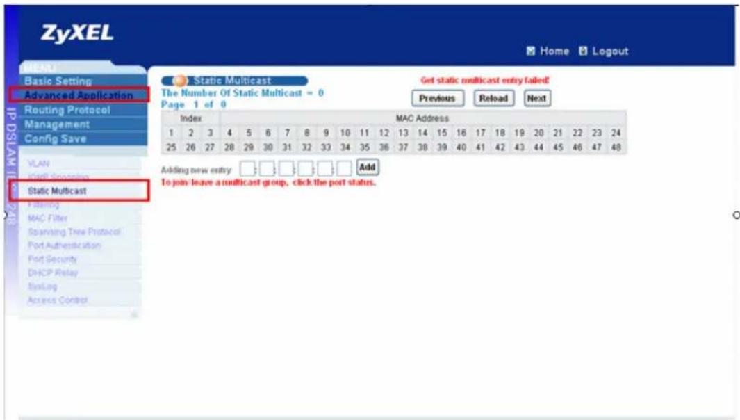
text_image
ZyXEL Home Logout Basic Setting Advanced Application Routing Protocol Management Config Save VLAN FATR Specification Static Multicast Filtering MAC Filter Spanishing Tree Protocol Port Authentication Port Security DHCP Relay EnLink Access Control Static Multicast The Number Of Static Multicast = 0 Page 1 of 0 Get static multicast entry failed! Previous Reload Next Index MAC Address 1 2 3 4 5 6 7 8 9 10 11 12 13 14 15 16 17 18 19 20 21 22 23 24 25 26 27 28 29 30 31 32 33 34 35 36 37 38 39 40 41 42 43 44 45 46 47 48 Adding new entry: Added To join leave a multicast group, click the port status.- Please key in “01:00:5e:00:00:01” in the “Adding new entry” and click “Add” to bring up the following screen. “V” displays for member and “-” displays for non-member.
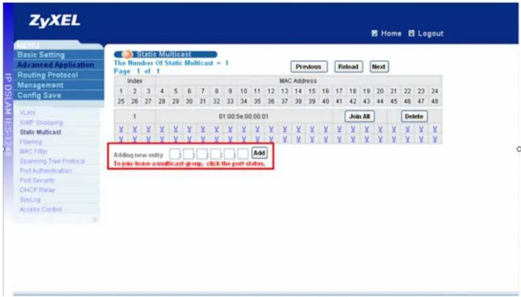
text_image
ZyXEL Home Logout MENU Basic Setting Advanced Application Routing Protocol Management Config Save IP DSLAM IES-1218 Static Multicast The Number Of Static Multicast = 1 Page 1 of 1 Previous Reload Next Index MAC Address 1 2 3 4 5 6 7 8 9 10 11 12 13 14 15 16 17 18 19 20 21 22 23 24 25 26 27 28 29 30 31 32 33 34 35 36 37 38 39 40 41 42 43 44 45 46 47 48 VLAN IOMF Snooping Static Multicast Filtering MAC Filter Spanning Tree Protocol Port Authentication Port Security DHCP Relay SysLog Access Controll 01:00:5e:00:00:01 Join All Delete ¥ ¥ ¥ ¥ ¥ ¥ ¥ ¥ ¥ ¥ ¥ ¥ ¥ ¥ ¥ ¥ ¥ ¥ ¥ ¥ ¥ ¥ ¥ ¥ ¥ ¥ ¥ ¥ ¥ ¥ ¥ ¥ ¥ ¥ ¥ ¥ ¥ ¥ ¥ ¥ ¥ ¥ ¥ ¥ ¥ ¥ ¥ ¥ ¥ ¥ ¥ ¥ ¥ ¥ ¥ ¥ ¥ ¥ ¥ ¥ ¥ ¥ ¥ ¥ ¥ ¥ ¥ ¥ ¥ ¥ ¥ ¥ ¥ ¥ ¥ ¥ ¥ ¥ ¥ ¥ ¥ ¥ ¥ ¥ ¥ ¥ ¥ ¥ ¥ ¥ ¥ ¥ ¥ ¥ ¥ ¥ ¥ ¥ ¥ ¥ ¥ Y Adding new entry □□□□□□□ Add To join leave a multicast group, click the port status.- Please do the same step to add "01:00:5e:00:00:02" static multicast entry.
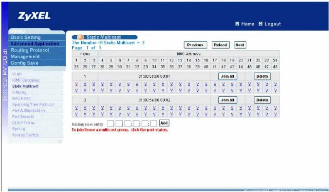
text_image
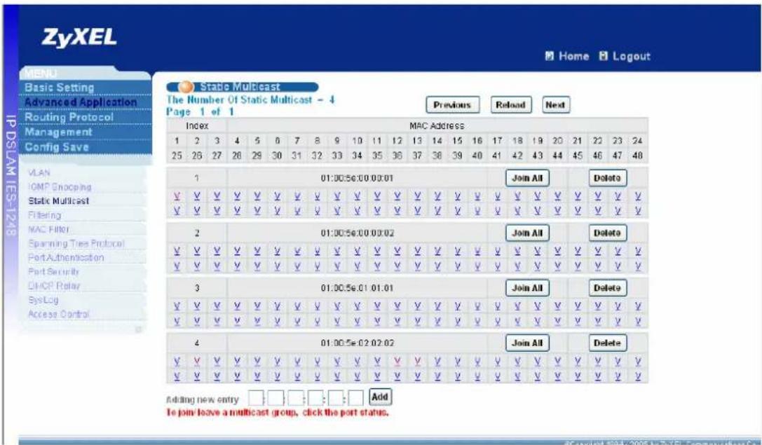
Zyxel Home Logout MENU Basic Setting Advanced Application Routing Protocol Management Config Save IP DSLAM IES-1218 State Multicast The Number Of Static Multicast - 2 Page 1 of 1 Previous Reload Next Index MAC Address 1 2 3 4 5 6 7 8 9 10 11 12 13 14 15 16 17 18 19 20 21 22 23 24 25 26 27 26 29 30 31 32 33 34 35 36 37 38 39 40 41 42 43 44 45 46 47 48 VLAN IOMF Enocping Static Multicast Filtering MAC Filter Spanning Tree Protocol Port Authentication Port Security CHCP Relay Sys Log Access Control 1 01:00:56:00 00:01 Join All Delete ✓ ✓ ✓ ✓ ✓ ✓ ✓ ✓ ✓ ✓ ✓ ✓ ✓ ✓ ✓ ✓ ✓ ✓ ✓ ✓ ✓ ✓ ✓ ✓ ✓ ✓ ✓ ✓ ✓ ✓ ✓ ✓ ✓ ✓ ✓ ✓ ✓ ✓ 2 01:00:56:00 00:02 弃入All Delete ✓ ✓ ✓ ✓ ✓ ✓ ✓ ✓ ✓ ✓ ✓ ✓ ✓ ✓ ✓ ✓ ✓ ✓ ✓ ✓ ✓ ✓ ✓ ✓ ✓ ✓ ✓ ✓ ✓ ✓ ✓ ✓ ✓ ✓ ✓ ✓ ✓ ✓ Adding new entry: Add To join leave a multicast (group, click the port status.- Please add channel 1 multicast MAC address "01:00:5e:01:01:01" and channel 2 multicast MAC address "01:00:5e:02:02:02" as above.
text_image
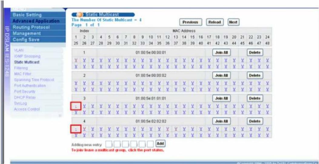
Zyxel Home Logout MENU Basic Setting Advanced Application Routing Protocol Management Config Save IP DSLAM IES-12/18 Static Multicast The Number Of Static Multicast - 4 Page 1 of 1 Previous Reload Next Index MAC Address 1 2 3 4 5 6 7 8 9 10 11 12 13 14 15 16 17 18 19 20 21 22 23 24 25 26 27 28 29 30 31 32 33 34 35 36 37 38 39 40 41 42 43 44 45 46 47 48 VLAN IOMF Snocping Static Multicast Filtering MAC Filter Spanning Tree Protocol Port Authentication Port Security CHCP Relay SysLog Access Control 1:00:56:00 00:01 Join All Delete ✓✓✓✓✓✓✓✓✓✓✓✓✓✓✓✓✓✓✓✓✓✓✓✓✓✓✓✓✓✓✓✓✓✓✓✓✓✓✓✓✓✓✓✓✓✓✓✓✓✓✓✓✓✓✓✓✓✓✓✓✓✓✓✓✓✓✓✓✓✓✓✓✓✓✓✓✓✓✓✓✓✓✓✓✓✓✓✓✓✓✓✓✓✓✓✓✓✓✓✓ ✓ 2:00:56:00 00:02 Join All Delete ✓ ✓ ✓ ✓ ✓ ✓ ✓ ✓ ✓ ✓ ✓ ✓ ✓ ✓ ✓ ✓ ✓ ✓ ✓ ✓ ✓ ✓ ✓ ✓ ✓ ✓ ✓ ✓ ✓ ✓ ✓ ✓ ✓ ✓ ✓ ✓ ✓ ✓ ✓ ✓ ✓ ✓ ✓ ✓ ✓ ✓ ✓ ✓ ✓ ✓ ✓ ✓ ✓ ✓ ✓ ✓ ✓ ✓ ✓ ✓ ✓ ✓ ✓ ✓ ✓ ✓ ✓ ✓ ✓ ✓ ✓ ✓ ✓ ✓ ✓ ✓ ✓ ✓ ✓ ✓ ✓ ✓ ✓ ✓ ✓ ✓ ✓ ✓ 3:00:56:01 01:01 Join All Delete ✓ ✓ ✓ ✓ ✓ ✓ ✓ ✓ ✓ ✓ ✓ ✓ ✓ ✓ ✓ ✓ ✓ ✓ ✓ ✓ ✓ ✓ ✓ ✓ ✓ ✓ ✓ ✓ ✓ ✓ ✓ ✓ ✓ ✓ ✓ ✓ ✓ ✓ ✓ ✓ ✓ ✓ ✓ ✓ 4:00:56:02 02:02 Join All Delete ✓ ✓ ✓ ✓ ✓ ✓ ✓ ✓ ✓ ✓ ✓ ✓ ✓ ✓ ✓ ✓ ✓ ✓ ✓ ✓ ✓ ✓ ✓ ✓ Add Adding new entry :□□□;□;□ Add To join leave a multicast group, click the port status. © 2005 in Zyxel Logistics Co.- Because port 1 is not member of both 2 channels, so it should be set as non-member of these 2 channels. Please single-click “port 1” to change its status of group address “01:00:5e:01:01:01” and “01:00:5e:02:02:02” as non-member.
text_image
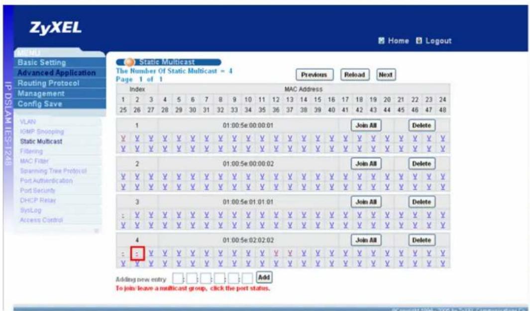
Static Multicast The Number Of Static Multicast - 4 Page 1 of 1 Previous Reload Next Index MAC Address 1 2 3 4 5 6 7 8 9 10 11 12 13 14 15 16 17 18 19 20 21 22 23 24 25 26 27 28 29 30 31 32 33 34 35 36 37 38 39 40 41 42 43 44 45 46 47 48 1 01:00:5e:00:00:01 Join AB Delete V V V V V V V V V V V V V V V V V V V V V V V V V V V V V V V V V V V V V V V V V V V V V V V V V V V V V V V V V V V V V V V V V V V V V V V V V V V V V V V V V V V V V V V V V V V V V V V V V V V V V Virginia V.V.V.V.V.V.V.V.V.V.V.V.V.V.V.V.V.V.V.V.V.V.V.V.V.V.V.V.V.V.V.V.V.V.V.V.V.V.V.V.V.V.V.V.V.V.V.V.V.V.V.V.V.V.V.V.V.V.V.V.V.V.V.V.V.V.V.V.V.V.V.V.V.V.V.V.V.V.V.V.V.V. 2 01:00:5e:00:00:02 Join AB Delete V.V.V.V.V.V.V.V.V.V.V.V.V.V.V.V.V.V.V.V.V.V.V.V.V.V.V.V.V.V.V.V.V.V.V.V.V.V.V.V.V.V-V.Y. V.V.V.V.V.V.V.V.V.V.V.V.V.V.V.V.V.V-V.Y. V.V.V.V.V. V. V. V. V. V. V. V. V. V. V. V. V. V. V. V. V. V. V. V. V. V. V. V. V. V. V. V. V. V. V. V. 3 01:00:5e:01:01:01 Join AB Delete - :V.\V.\V.\V.\V.\V.\V.\V.\V.\V.\V.\V.\V.\V.\V.\V.\V.\V.\V.\V.\V.\V.\V.\V.\V.\V.\V.\V.\V.\V.\V.\V. V.\V.\V.\V.\V.\V.\V.\V.\V.\V.\V.\V.\V.\V.\V.\V.\V.\V.\V.\V.\V.\V.\V.\V.\V.\V.\V. 4 01:00:5e:02:02:02 Join AB Delete - :V.\V.\V.\V.\V.\V.\V.\V.\V.\V.\V.\V.\V.\V.\V.\V.\V.\V.\V.\V.\V.\V.\V.\V.\V.\V.\V.\V.\V. A adding new entry Add To join leave a multicast group, click the port status.- For port 2, set it as non-member of channel 2 "01:00:5e:02:02:02"
text_image
ZyXEL Home Logout Static Multicast The Number Of Static Multicast = 4 Page 1 of 1 Previous Reload Next Index MAC Address 1 2 3 4 5 6 7 8 9 10 11 12 13 14 15 16 17 18 19 20 21 22 23 24 25 26 27 28 29 30 31 32 33 34 35 36 37 38 39 40 41 42 43 44 45 46 47 48 1 01:00:5e 00:00:01 Join All Delete ¥ ¥ ¥ ¥ ¥ ¥ ¥ ¥ ¥ ¥ ¥ ¥ ¥ ¥ ¥ ¥ ¥ ¥ ¥ ¥ ¥ ¥ ¥ ¥ ¥ ¥ ¥ ¥ ¥ ¥ ¥ ¥ ¥ ¥ ¥ ¥ ¥ ¥ ¥ ¥ ¥ ¥ ¥ ¥ ¥ 2 01:00:5e 00:00:02 Join All Delete ¥ ¥ ¥ ¥ ¥ ¥ ¥ ¥ ¥ ¥ ¥ ¥ ¥ ¥ ¥ ¥ ¥ ¥ ¥ ¥ ¥ ¥ ¥ ¥ ¥ ¥ ¥ ¥ ¥ ¥ ¥ ¥ ¥ ¥ ¥ ¥ ¥ 3 01:00:5e 01:01:01 Join All Delete = ¥ ¥ ¥ ¥ ¥ ¥ ¥ ¥ ¥ ¥ ¥ ¥ ¥ ¥ X Y V V V V V ¥ ¥ ¥ ¥ ¥ ¥ ¥ ¥ ¥ ¥ ¥ ¥ ¥ ¥ X Y V V V V V 4 01:00:5e 02:02:02 Join All Delete = - = = = = = = = = = = = = = = = = = = = = = = = = = = = = = = = = = = = = = = = = = = = = = = = = = = = Add Adding new entry □□□□□□□□□□□□□□□□□□□□□□□□□□□□□□□□□□□□□□□□□□□□□□□□□□□□□□□□□□□□□□□□□□□□□□□□□□□□□□□□□□□□□□□□□□□□□□□□□□□□□ To join leave a multicast group, click the port status.- For port 3, no need to change anything because its status as member of these channels by default. Don't forget to click "Config Save" to save your configuration into flash.
CLI Command related:
| switch Smcast | Use the static | multicast filter | |
| show | Display all addresses joined to ADSL ports | ||
| set | MAC> | Use join|leave to add/remove multicast |
MAC
| MAC address on specified ADSL ports, a range of ADSL ports or all ports, | ||||
| delete | Remove a static | multicast filter entry by deleting the associated MAC address. | ||
How to achieve the same goal by CLI command?
switch smcast set 1,2,3 01005e000001 join
switch smcast set 1,2,3 01005e000002 join
switch smcast set 1 01005e010101 leave
switch smcast set 2,3 01005e010101 join
switch smcast set 1,2 01005e020202 leave
switch smcast set 3 01005e020202 join
switch smcast show
Static Mcast Groups
J: join L: leave
index MAC address
123456789012345678901234567890123456789012345678
| 1 | 01:00:5e:00:00:01 | JJJLLLLLLLLLLLLLLLLLLLLLLLLLLLLLLLLLLLLLLLLLLLLLLLLLLLLLLLLLLLLLLLLLLLLLLLLLLLLLLLLLLLLLLLLLLLLLLLLLLLLLLLLLLLLLLLLLLLLLLLLLLLLLLLLLLLLLLLLLLLLLLLLLLLLLLLLLLLLLLLLLLLLLLLLLLLLLLLLLLLLLLLLLLLLLLLLLLLLLLLLLLLLLLLLLLLLLLLLLLLLLLLLLLLLLLLLLLLLLLLLLLLLLLLLLLLLLLLLLLLLLLLLLLLLLLLLLLLLLLLLLLLLLLLLLLLLLLLLLLLLLLLLLLLLLLLLLLLLLLLLLLLLLLLLLLLLLLLLLLLLLLLLLLLLLLLLLLLLLLLLLLLLLLLLLLLLLLLLLLLLLLLLLLLLLLLLLLLLLLLLLL |
| 2 | 01:00:5e:00:00:02 | JJJLLLLLLLLLLLLLLLLLLLLLLLLLLLLLLLLLLLLLLLLLLLLLLLLLLLLLLLLLLLLLLLLLLLLLLLLLLLLLLLLLLLLLLLLLLLLLLLLLLLLLLLLLLLLLLLLLLLLLLLLLLLLLLLLLLLLLLLLLLLLLLLLLLLLLLLLLLLLLLLLLLLLLLLLLLLLLLLLLLLLLLLLLLLLLLLLLLLLLLLLLLLLLLLLLLLLLLLLLLLLLLLLLLLLLLLLLLLLLLLLLLLLLLLLLLLLLLLLLLLLLLLLLLLLLLLLLLLLLLLLLLLLLLLLLLLLLLLLLLLLLLLLLLLLLLLLLLLLLLLLLLLLLLLLLLLLLLLLLLLLLLLLLLLLLLLLLLLLLLLLLLLLLLLLLLLLLLLLLLLLLLLLll |
| 3 | 01:00:5e:01:01:01 | LJJJLLLLLLLLLLLLLLLLLLLLLLLLLLLLLLLLLLLLLLLLLLLLLLLLLLLLLLLLLLLLLLLLLLLLLLLLLLLLLLLLLLLLLLLLLLLLLLLLLLLLLLLLLLLLLLLLLLLLLLLLLLLLLLLLLLLLLLLLLLLLLLLLLLLLLLLLLLLLLLLLll |
| 4 | 01:00:5e:02:02:02 | LLJJLLLLLLLLLLLLLLLLLLLLLLLLLLLLLLLLLLLLLLLLLLLLLLLLLLLLLLLLLLLLLLLLLLLLLLLLLLLLLLLLLLLLll |
PS: Default statuses of other ADSL ports without configuration are DIFFERENT between WEB GUI (default status is Join) and CLI Command (Default status is Leave), so please choose the better way to do static multicast filter configuration to get most convenience.
Limit the users behind the certain DSL port
ISP may want to limit the number of PC behind certain DSL port to access the Internet or allow PCs with specific MAC address to access the Internet. They can easily to achieve this with Port Security and MAC filter features.
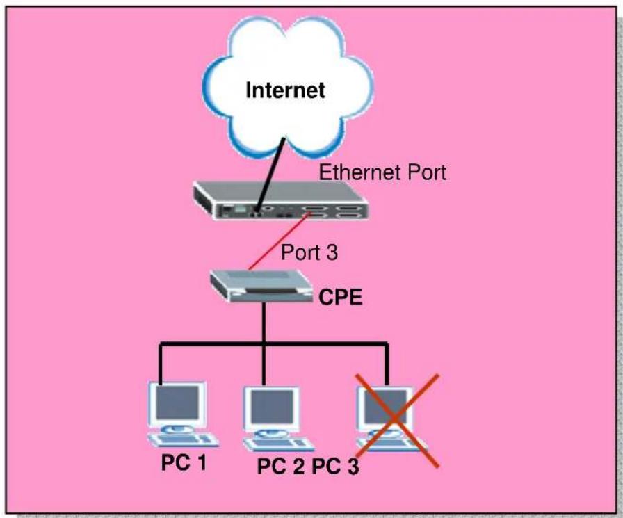
flowchart
graph TD
    A["Internet"] --> B["Ethernet Port"]
    B --> C["Port 3"]
    C --> D["CPE"]
    D --> E["PC 1"]
    D --> F["PC 2"]
    D --> G["PC 3"]
    style A fill:#fff,stroke:#000
    style B fill:#ccc,stroke:#000
    style C fill:#ccc,stroke:#000
    style D fill:#ccc,stroke:#000
    style E fill:#fff,stroke:#000
    style F fill:#fff,stroke:#000
    style G fill:#fff,stroke:#000
How to set up MAC Filter/Port Security
Here, we will set up an environment to allow PCs with certain MAC address and the number of PCs behind port 3 to access the Internet.
1. IES-1248 settings
1.1 Set up MAC filter
Click Advanced Application, MAC Filter in the navigation panel to display configuration screen as shown. You will see the MAC Filter setup page. Select the Port 3 and input the MAC address you allow to access the Internet. And don’t forget the press Apply button to let it takes effect.
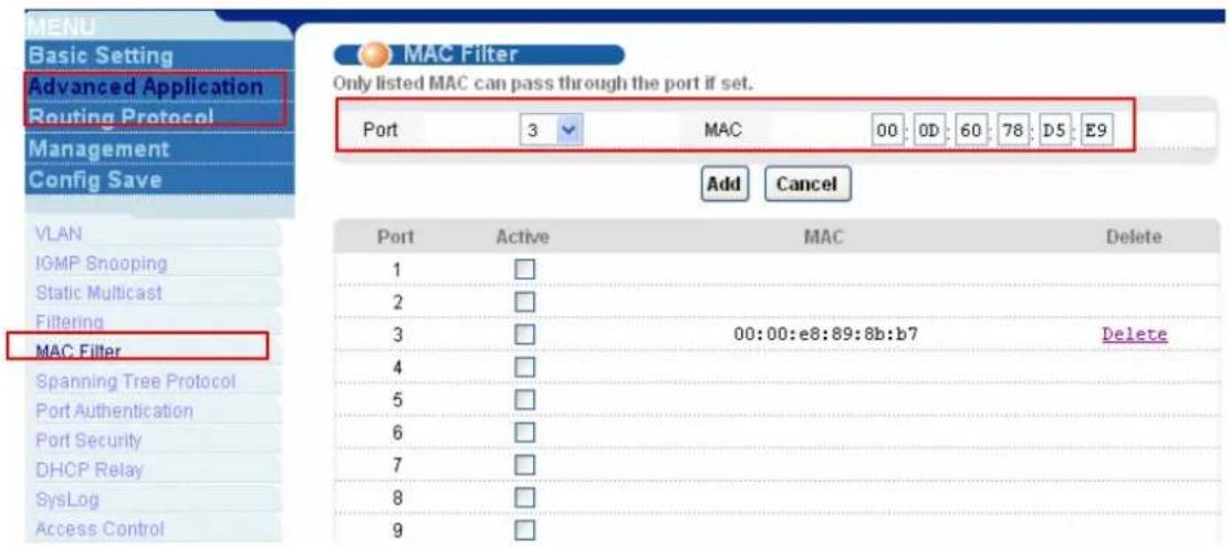
text_image
MENU Basic Setting Advanced Application Routing Protocol Management Config Save VLAN IGMP Snooping Static Multicast Filtering MAC Filter Spanning Tree Protocol Port Authentication Port Security DHCP Relay SysLog Access Control MAC Filter Only listed MAC can pass through the port if set. Port 3 MAC 00 0D 60 78 DS E9 Add Cancel Port Active MAC Delete 1 □ 2 □ 3 □ 00:00:e8:89:8b:b7 Delete 4 □ 5 □ 6 □ 7 □ 8 □ 9 □You will see the MAC address in the MAC field. Then check the Active check box of Port 3 and press Apply button to enable this feature. Only the MAC addresses listed here can access the Internet behind certain ports.
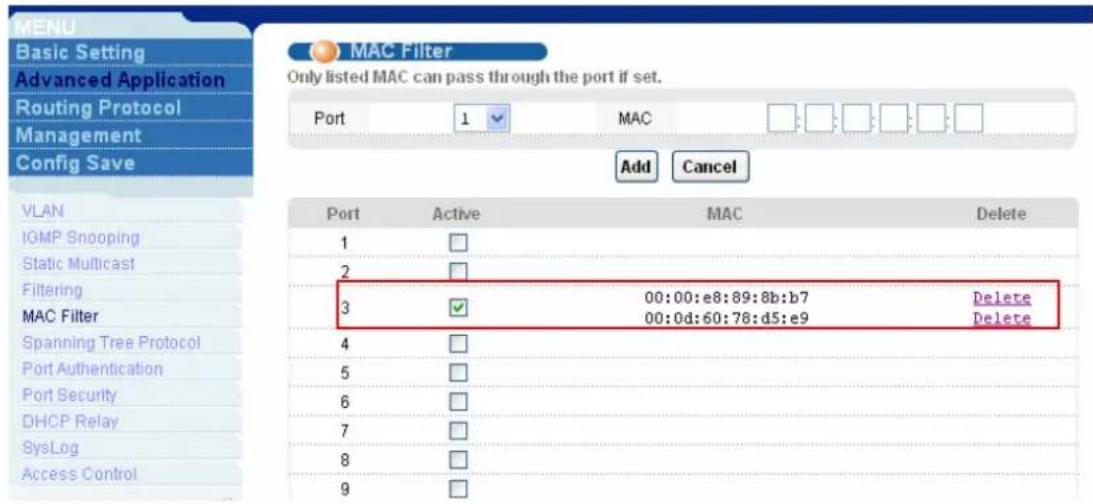
text_image
MENU Basic Setting Advanced Application Routing Protocol Management Config Save VLAN IGMP Snooping Static Multicast Filtering MAC Filter Spanning Tree Protocol Port Authentication Port Security DHCP Relay SysLog Access Control MAC Filter Only listed MAC can pass through the port if set. Port 1 MAC Add Cancel Port Active MAC Delete 1 □ 2 □ 3 ✓ 00:00:e8:89:8b:b7 Delete 00:0d:60:78:d5:e9 Delete 4 □ 5 □ 6 □ 7 □ 8 □ 9 □1.2 Set up Port Security
Click Advanced Application, Port Security in the navigation panel to display configuration screen as shown. You will see the Port Security setup page. Check the Enable check box of Port 3 and input the MAC address number you want to limit to access the Internet. And don't forget the press Apply button to let it takes effect. Note that the MAC filter and Port security can't be used at the same time.
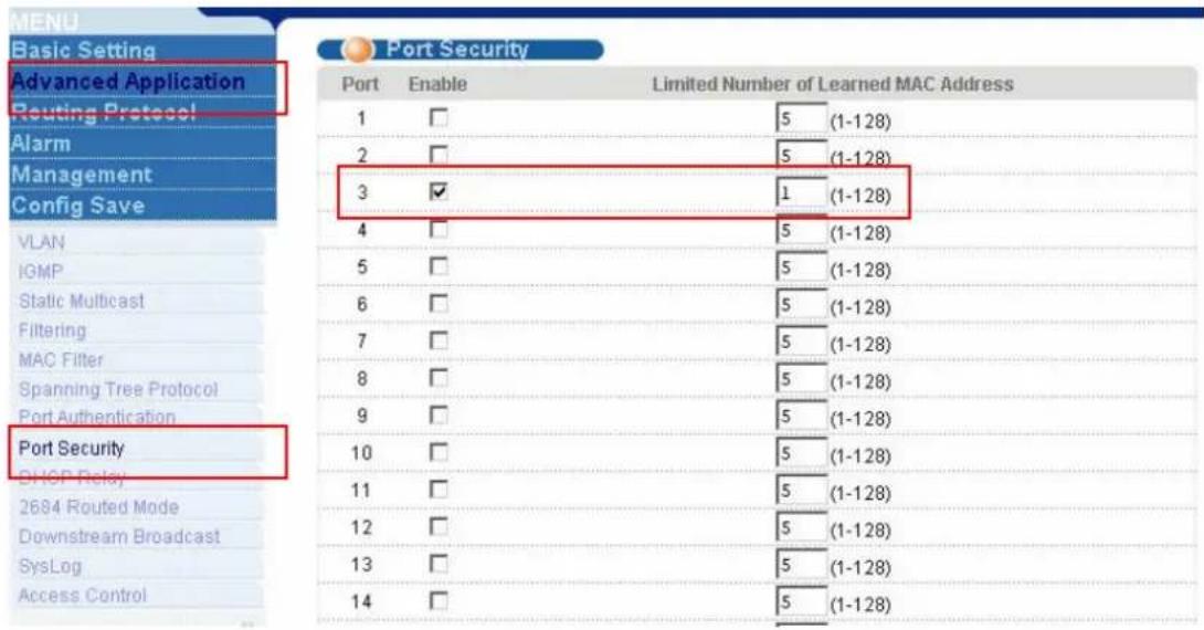
text_image
MENU Basic Setting Advanced Application Routing Protocol Alarm Management Config Save VLAN IGMP Static Multicast Filtering MAC Filter Spanning Tree Protocol Port Authentication Port Security DHCP Relay 2684 Routed Mode Downstream Broadcast SysLog Access Control Port Security Port Enable Limited Number of Learned MAC Address 1 □ 5 (1-128) 2 □ 5 (1-128) 3 ✓ 1 (1-128) 4 □ 5 (1-128) 5 □ 5 (1-128) 6 □ 5 (1-128) 7 □ 5 (1-128) 8 □ 5 (1-128) 9 □ 5 (1-128) 10 □ 5 (1-128) 11 □ 5 (1-128) 12 □ 5 (1-128) 13 □ 5 (1-128) 14 □ 5 (1-128)Click Management, MAC Table in the navigation panel to display configuration screen as shown. And select port 3. You will see the MAC table will be shown as you configured in previous steps.

text_image
MENU Basic Setting Advanced Application Routing Protocol Management Config Save Maintenance Diagnostic MAC Table ARP Table MAC Table Get Time 1970:01:01 00:48:03 Page 1 of 1 Previous Next Show 3 Index MAC Port V/D V/D VCI 1 00:0d:60:78:d5:e9 3 1 0/ 33 Refresh FlushDHCP Relay Option 82 Application
ISP may want to limit the number of IP address or deliver some specific IP addresses according to certain DSL port, VLAN ID and option 82 string. They can easily to achieve this with DHCP Relay Option 82 feature and a DHCP server supporting Option 82 function.

flowchart
graph TD
    A["DHCP Server"] --> B["Network"]
    B --> C["Ethernet Port"]
    C --> D["Port 25"]
    D --> E["CPE"]
    E --> F["DHCP Client"]
How to set up DHCP Relay Option 82 Environment
Here, we will set up an environment to allow a PC get DHCP IP address in specific IP pool according to its DSL port, VLAN ID and the option 82 string. In this case, the PC is behind 25^th DSL port and the option 82 string is a string “1248”. We use the IP Commander as DHCP server. Its IP is 192.168.1.99 and the IP pool is between 192.168.1.201 and 192.168.1.203 for VID=1, DSL port=25 and the option 82 string is “1248”.
1. IES-1248 settings
Click Advanced Application, DHCP Relay in the navigation panel to display configuration screen as shown. You will see the DHCP Relay setup page. Enable the DHCP relay and Option 82 function. Fill the IP address of DHCP server in this page. The IP address is 192.168.1.99 in our case. Also, enter “1248” as the Option 82 string.
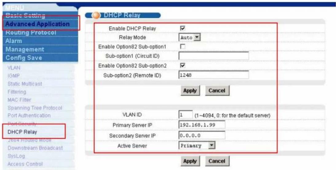
text_image
MENU Basic Setting Advanced Application Routing Protocol Alarm Management Config Save VLAN IGMP Static Multicast Filtering MAC Filter Spanning Tree Protocol Port Authentication Port Security DHCP Relay 2684 Routed Mode Downstream Broadcast SysLog Access Control DHCP Relay Enable DHCP Relay ✓ Relay Mode Auto ✓ Enable Option82 Sub-option1 ✓ Sub-option1 (Circuit ID) Enable Option82 Sub-option2 ✓ Sub-option2 (Remote ID) 1248 Apply Cancel VLAN ID 1 (1~4094, 0: for the default server) Primary Server IP 192.168.1.99 Secondary Server IP 0.0.0.0 Active Server Primary ✓ Apply Cancel2. CPE settings
Connect CPE to the 25 ^th DSL port. Please see former applications for Detailed settings.
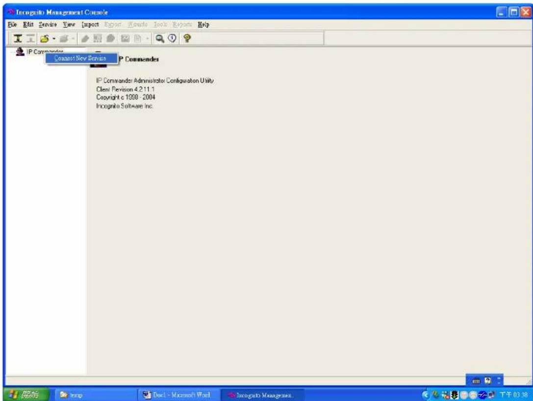
3. IP Commander settings
Open IP Commander. Right click "IP commander and then click "connect new server".
text_image
Incognito Management Console File Edit Service View Import Export Tools Reports Help IP Commander Commander New Service P Commanders IP Commander Administrator Configuration Utility Client Revision 4.2.11.1 Copyright c 1990 - 2004 Incognito Software Inc. 开始 Temp Doc - Microsoft Word Incognito Management 下午03:38Input the DHCP IP address or domain name and click "ok". Our IP is 192.168.1.99.

text_image
Incognito Management Console File Edit Service Save Import Report Wizard Tools Reports Help IP Commander IP Commander IP Commander Administrator Configuration Utility Client Revision 4.211.1 Copyright c 1998 - 2004 Incognito Software Inc. Select Server Please enter the name of the server with the IP Commander service you would like to manage. 192.168.1.58 OK CancelInput user name and password. The default user name is “administrator” and password is “incognito”.

text_image
Inoguchi Management Console File Edit Service View Export Report Manuals Tools Reports Help IP Commander IP Commander IP Commander: Administrator Configuration Utility Client Revision 4.211.1 Copyright c 1998 - 2004 Inoguchi Software Inc. IP Commander You must login using an IP Commander: service administrator account on 192.168.1.99 (not a Winnt or Link user account). Login name administrator Password Save Password OK CancelIt will bring up the following screen, please make sure that your DHCP is in “online” status. Then click “wizard” in the top tool bars and select “rule wizard”.
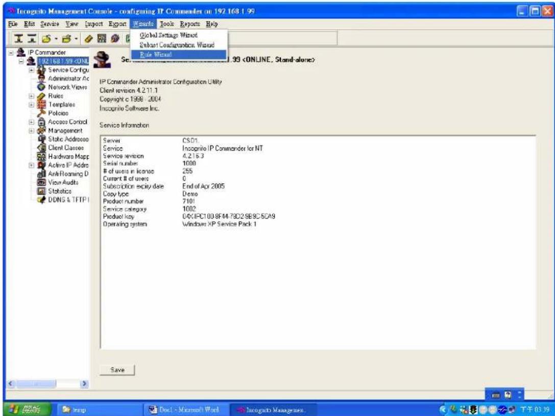
text_image
Incognito Management Console - configuring IP Commander on 192.168.1.99 File Edit Service View Import Export Wizards Tools Reports Help Global Settings Wizard Subset Configuration Wizard Rule Wizard IP Commander Administrator Configuration Utility Client revision 4.2.11.1 Copyright c 1998 - 2004 Inscognito Software Inc. Service Information Server CSD1. Service Incognito IP Commander for NT Service revision 4.2.15.3 Serial number 1000of users in license 255
Current # of users 0 Subscription expiry date End of Apr 2005 Copy type Demo Product number 7101 Service category 1002 Product key 04X-IPC100.8F44.78D2.9B9C.SCA9 Operating system Windows XP Service Pack 1 SaveGive a name and description to the new rule.

text_image
Incognito Management Console - configuring IP Commander on 192.168.1.99Assign a range of IP addresses or just one IP address to this rule. In our case, we set the IP pool from 192.168.1.201 to 192.168.1.203.
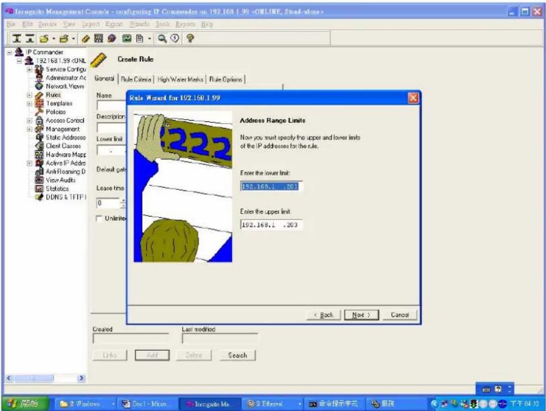
text_image
Inogede Management Console - configuring IP Commander on 192.168.1.99After input IP pool, we select "DHCP Option" in Keywords combobox.
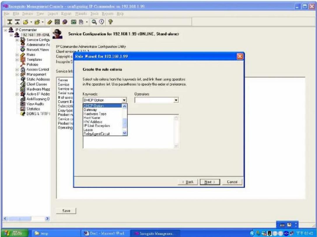
text_image
Incognito Management Console - configuring IP Commander on 192.168.1.99 File Edit Service View Import Export Wizard Tools Window Help IP Commander 192.168.1.99After select the “DHCP Option”, it will pop up “Add DHCP Option Rule” dialog.
Select “option 82 Relay Agent Information”, sub-option 1, binary data. For port 25, VLAN 1, “1248”, please key in “0019000131323438” as the key value and click OK. Please note that the first 2 bytes define port number, the second 2 bytes is VLAN ID and the other bytes are the Option 82 string.
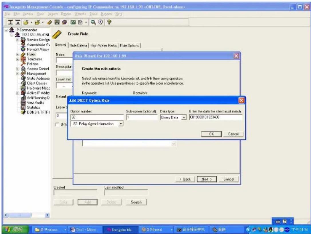
text_image
Inogenetic Management Console - configuring IP Commander on 192.168.1.99After you finish above step, you will see the following figure.
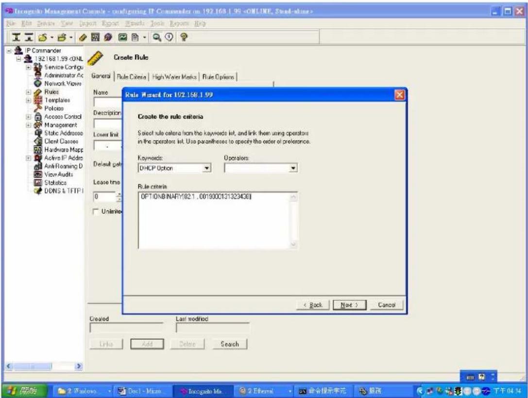
text_image
Inocogdo Management Console - configuring IP Commander on 192.168.1.99Then pop up the following screen and you can just press Next button.

text_image
Incognito Management Console - configuring IP Commander on 192.168.1.99 File Edit Services View Import Export Documents Book Review Help IP Commander 192.168.1.99Then you can add DHCP template (option) such as gateway, DNS server and so on.
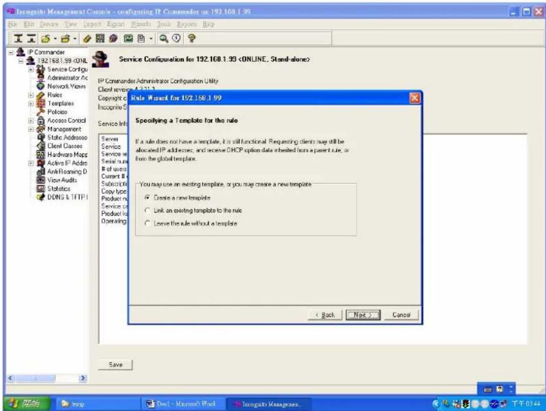
text_image
Inogels Management Console - configuring IP Commander on 192.168.1.99 File Edit View View Import About Tools Book About Help IP Commander 192.168.1.99Here we use "192.168.1.1" as gateway IP address of DHCP client PC.
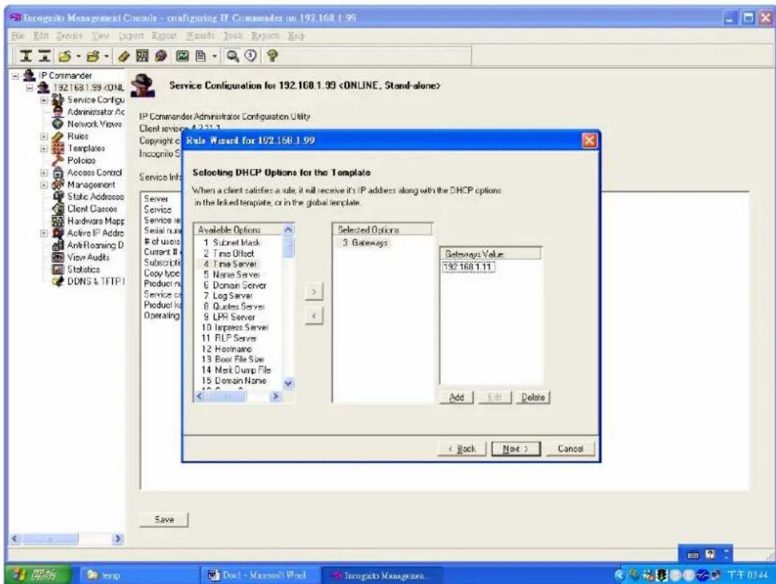
text_image
Incognito Management Console - configuring IP Commander on 192.168.1.99 File Edit Services View Export Report Words Book Reports Help IP Commander 192.168.1.99You can apply DDNS service to DHCP server or not.
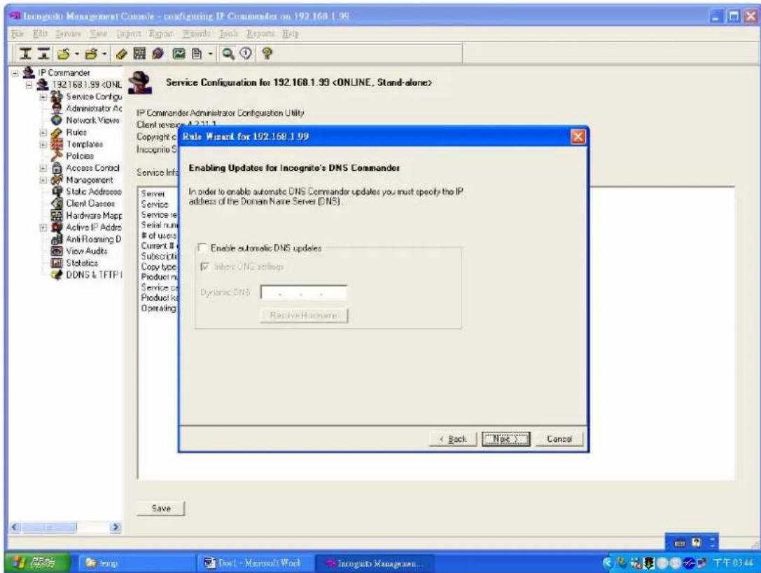
text_image
Inogrite Management Console - configuring IP Commander on 192.168.1.99 File Edit View View Import Report Wizard Tools Reports Help IP Commander 192.168.1.99The rule creation has been finished.

text_image
Incognito Management Console - configuring IP Commander on 192.168.1.99 File Edit Services View Import Export Results Tools Options Help IP Commander 192.168.1.99After finishing all above procedures, your PC will get the IP address 192.168.1.201 when you send a DHCP request.
Filter Some Certain Packet
ISP may want to filter some kinds of packets. IES-1248 provides “Packet Filter” function to filter some specific packets, like IP, ARP, DHCP, EAPoL, PPPoE, NETBIOS and IGMP.

flowchart
graph TD
    A["Client 1"] --> B["CPE"]
    B --> C["Ethernet Port"]
    C --> D["Network"]
    D --> E["Client 2"]
    style A fill:#f9f,stroke:#333
    style B fill:#f9f,stroke:#333
    style C fill:#f9f,stroke:#333
    style D fill:#ccf,stroke:#333
    style E fill:#ccf,stroke:#333
    note right of D Specific Protocol Packet. Ex. NetBIOS
How to Filter Some Specific Packet
Here, we will set up an environment to block NETBIOS protocol packets.
1. IES-1248 settings
Click Advanced Application, Filter in the navigation panel to display configuration screen as shown. You will see the Packet Filter setup page.

text_image
MENU Basic Setting Advanced Application Routing Protocol Management Config Save VLAN IGMP Snooping Static Multicast Filtering MAC Filter Spanning Tree Protocol Port Authentication Port Security DHCP Relay SysLog Access Control Packet Filter Port 1 PPPoE ✓ Pass through IP ✓ Pass through ARP ✓ Pass through NetBios ✓ Pass through DHCP ✓ Pass through EAPOL ✓ Pass through IGMP ✓ Pass through Add Cancel V: Pass through, --: Filter out. Port PPPoE IP ARP NetBios DHCP EAPOL IGMP 1 V V V V V V V V 2 V V V V V V V V 3 V V V V V V V V 4 V V V V V V V V 5 V V V V V V V V 6 V V V V V V V VPlease select port 1 and clear the NetBios check box. Meanwhile, you will see Filter Out in NetBios check box. Press Add button make the change take effect.
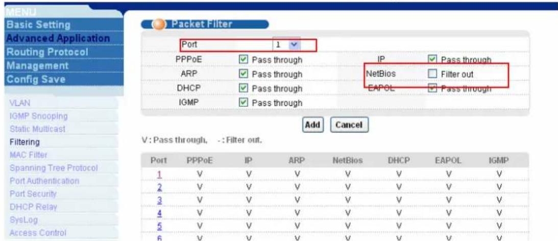
text_image
MENU Basic Setting Advanced Application Routing Protocol Management Config Save VLAN IGMP Snooping Static Multicast Filtering MAC Filter Spanning Tree Protocol Port Authentication Port Security DHCP Relay SysLog Access Control Packet Filter Port 1 PPPoE Pass through IP Pass through ARP Pass through NetBios Filter out DHCP Pass through EAPOL Pass through IGMP Pass through Add Cancel V: Pass through, -: Filter out. Port PPPoE IP ARP NetBios DHCP EAPOL IGMP 1 V V V V V V V V 2 V V V V V V V V V 3 V V V V V V V V V 4 V V V V V V V V V 5 V V V V V V V V V 6 V V V V V V V VSo you will see the port 1 will block the NetBios protocol packets.
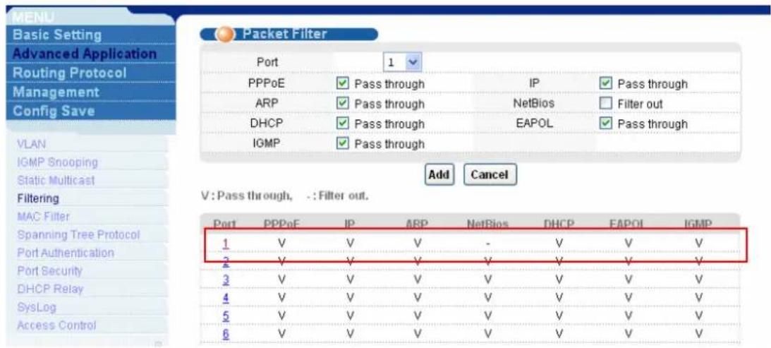
text_image
MENU Basic Setting Advanced Application Routing Protocol Management Config Save VLAN IGMP Snooping Static Multicast Filtering MAC Filter Spanning Tree Protocol Port Authentication Port Security DHCP Relay SysLog Access Control Packet Filter Port 1 PPPoE Pass through IP Pass through ARP Pass through NetsBios Filter out DHCP Pass through EAPOL Pass through IGMP Pass through Add Cancel V: Pass through, -: Filter out. Port PPPoE IP ARP NetBios DHCP EAPOL IGMP 1 V V V - V V V 2 V V V V V V V V 3 V V V V V V V V V 4 V V V V V V V V V 5 V V V V V V V V V 6 V V V V V V V V VCascade two IES1248 (Daisy chain mode)
You know, the IES1248 is a remote mini-DSLAM. When the subscriber number is increased, ISPs may cascade or daisy-chain the more then one IES1248 to extend the port number. They can daisy-chain up to three IES1248.
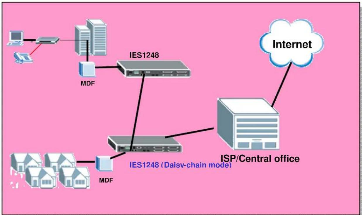
flowchart
graph TD
    A["Computer"] --> B["Desktop"]
    B --> C["IE51248"]
    C --> D["MDF"]
    D --> E["ISP/Central office"]
    E --> F["Internet"]
    C --> G["IE51248 (Daisv-chain mode)"]
    G --> H["MDF"]
    H --> I["ISP/Central office"]
How to setup Daisy-chain mode
In this case, we daisy-chain two IES1248. Please see the figure above. We only set the one connected to the ISP as Daisy-Chain mode. In Daisy-Chain mode, connect the Ethernet Port 1 to the Ethernet backbone and connect the Ethernet Port 2 to another IES1248. Note that we don't suggest using loop network topology while using daisy-chain mode.
1. IES-1248 settings
Click Basic Setting, Switch setup in the navigation panel to display configuration screen as shown. You will see the Switch setup page. In Switch Mode combobox, select the Daisy chain. Don't forget press Apply button to let the setting take effect.
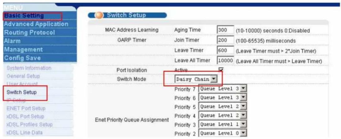
text_image
MENU Basic Setting Advanced Application Routing Protocol Alarm Management Config Save System Information General Setup User Account Switch Setup IP Setup ENET Port Setup xDSL Port Setup xDSL Profiles Setup xDSL Line Data Switch Setup MAC Address Learning GARP Timer Leave Timer Leave All Timer Active Switch Mode Daisy Chain Priority 7 Queue Level 3 Priority 6 Queue Level 3 Priority 5 Queue Level 2 Priority 4 Queue Level 2 Priority 3 Queue Level 1 Priority 2 Queue Level 0VLAN Application
Application Scenario A:

flowchart
graph TD
    subgraph_Server_Rack1["Server Rack"]
        A1["Server 1"] --> B1["Finance Port 24"]
        A2["Server 2"] --> B2["Finance Port 24"]
        A3["Server 3"] --> B3["Finance Port 24"]
    end
    subgraph_Server_Rack2["Server Rack"]
        C1["Server 1"] --> D1["Finance Port 24"]
        C2["Server 2"] --> D2["Finance Port 24"]
        C3["Server 3"] --> D3["Finance Port 24"]
    end
    style Server_Rack1 fill:#f9f,stroke:#333
    style Server_Rack2 fill:#f9f,stroke:#333
    note1["Sales: Port 1, 2, 3\nFinance: Port 4, 5, 6"] --> A1
    note2["Sales: Port 1, 2, 3\nFinance: Port 4, 5, 6"] --> C1
Scenario Description
In this scenario, each building has 2 departments, and users belong to the same
department could communicate with each other, but communication between different departments is forbidden for security and confidential reason.
PCs from Sales department (VLAN 10) connected to Port 1, 2, 3 of both switches while Finance department (VLAN 20) using Port 4, 5, 6 connected to switches. Because this is a symmetric switch setting, so configuration of both switches are same.
How to configure VLAN:
- Please enter VLAN setting under Advanced Application menu and click “static VLAN” to bring up the following screen, adding VLAN 10: port 1, fixed, untag; port 2, fixed, untag; port 3, fixed, untag; port 24, fixed, Tx tagging.

text_image
ZyXEL Status Logout Help MENU Basic Setting Advanced Application Routing Protocol Management Static VLAN VLAN Status ACTIVE Name VLAN10 VLAN Group ID 10 VLAN Static MAC Forwarding Filtering Spanning Tree Protocol Bandwidth Control Broadcast Storm Control Mirroring Link Aggregation Port Authentication Port Security Access Control Quoung Method Classifier Policy Rule VLAN Stacking DHOP Relay Port Control Tagging 1 Normal Fixed Forbidden Tx Tagging 2 Normal Fixed Forbidden Tx Tagging 3 Normal Fixed Forbidden Tx Tagging 4 Normal Fixed Forbidden Tx Tagging 5 Normal Fixed Forbidden Tx Tagging 6 Normal Fixed Forbidden Tx Tagging 7 Normal Fixed Forbidden Tx Tagging 8 Normal Fixed Forbidden Tx Tagging 9 Normal Fixed Forbidden Tx Tagging 10 Normal Fixed Forbidden Tx Tagging 11 Normal Fixed Forbidden Tx Tagging 12 Normal Fixed Forbidden Tx Tagging 13 Normal Fixed Forbidden Tx Tagging 14 Normal Fixed Forbidden Tx Tagging 15 Normal Fixed Forbidden Tx Tagging- Follow the above step to add VLAN 20: port 4, fixed, untag; port 5, fixed, untag; port 6 fixed, untag. port 24, fixed, Tx tagging.
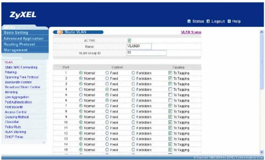
text_image
ZyXEL Status Logout Help MENU Basic Setting Advanced Application Routing Protocol Management Static VLAN VLAN Status ACTIVE Name VLAN0 VLAN Group ID 20 VLAN Static MAC Forwarding Filtering Spanning Tree Protocol Bandwidth Control Broadcast Storm Control Mirroring Link Aggregation Port Authentication Port Security Access Control Quuing Method Classifier Policy Rule VLAN Stacking DHOP Relay Port Control Tagging 1 Normal Fixed Forbidden Tx Tagging 2 Normal Fixed Forbidden Tx Tagging 3 Normal Fixed Forbidden Tx Tagging 4 Normal Fixed Forbidden Tx Tagging 5 Normal Fixed Forbidden Tx Tagging 6 Normal Fixed Forbidden Tx Tagging 7 Normal Fixed Forbidden Tx Tagging 8 Normal Fixed Forbidden Tx Tagging 9 Normal Fixed Forbidden Tx Tagging 10 Normal Fixed Forbidden Tx Tagging 11 Normal Fixed Forbidden Tx Tagging 12 Normal Fixed Forbidden Tx Tagging 13 Normal Fixed Forbidden Tx Tagging 14 Normal Fixed Forbidden Tx Tagging 15 Normal Fixed Forbidden Tx Tagging- Please click VLAN port setting to bring up the following screen, setup PVID 10 for port 1, port 2, port 3; PVID 20 for port 4, port 5, port 6.

text_image
ZyXEL Status Logout Help VLAN Port Setting VLAN Status GVRP Port Isolation VLAN Port Ingress Check PVD GVRP Acceptable Frame Type VLAN Trunking 1 10 All 2 10 All 3 10 All 4 20 All 5 20 All 6 20 All 7 1 All 8 1 All 9 1 All 10 1 All 11 1 All 12 1 All 13 1 All 14 1 All © Copyright 1995-2004 by SyXEL Communications Corp.Application Scenario B:
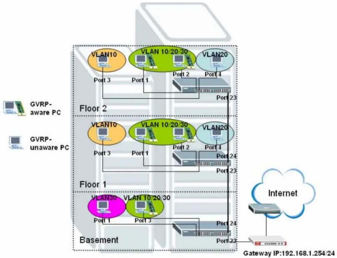
flowchart
graph TD
    subgraph Floor 1
        A["VLAN30"] --> B["Port 1"]
        A --> C["Port 3"]
        D["VLAN 10 20 30"] --> E["Port 1"]
        F["VLAN10"] --> G["Port 3"]
        H["VLAN 10 20 30"] --> I["Port 1"]
        J["VLAN20"] --> K["Port 2"]
        L["VLAN20"] --> M["Port 4"]
        N["VLAN10"] --> O["Port 2"]
        P["VLAN20"] --> Q["Port 4"]
        R["VLAN10"] --> S["Port 23"]
        T["VLAN20"] --> U["Port 23"]
    end
    subgraph Floor 2
        V["VLAN10"] --> W["Port 3"]
        X["VLAN10 20 30"] --> Y["Port 1"]
        Z["VLAN10"] --> AA["Port 3"]
        AB["VLAN10 20 30"] --> AC["Port 1"]
        AD["VLAN20"] --> AE["Port 2"]
        AF["VLAN20"] --> AG["Port 4"]
        AH["VLAN10"] --> AI["Port 2"]
        AJ["VLAN10 20 30"] --> AK["Port 1"]
        AL["VLAN20"] --> AM["Port 4"]
        AN["VLAN10"] --> AO["Port 23"]
    end
    subgraph Basement
        AP["VLAN30"] --> AQ["Port 1"]
        AR["VLAN 10 20 30"] --> AS["Port 3"]
        AT["VLAN20"] --> AU["Port 24"]
        AV["VLAN20"] --> AW["Port 23"]
    end
    G["Internet"] --> GatewayIP["Gateway IP:192.168.1.254/24"]
    style G fill:#f9f,stroke:#333
    style H fill:#ccf,stroke:#333
    style I fill:#cfc,stroke:#333
    style AJ fill:#fcc,stroke:#333
    style AK fill:#cff,stroke:#333
    style AL fill:#ffc,stroke:#333
    style AM fill:#cfc,stroke:#333
    style AN fill:#fcc,stroke:#333
    style AP fill:#cfc,stroke:#333
    style AR fill:#fcc,stroke:#333
    style AS fill:#cfc,stroke:#333
    style AT fill:#fcc,stroke:#333
    style AU fill:#cfc,stroke:#333
    style V fill:#cfc,stroke:#333
    style W fill:#cfc,stroke:#333
    style AC fill:#cfc,stroke:#333
    style AN fill:#cfc,stroke:#333
    style AL fill:#cfc,stroke:#333
    style AN fill:#cfc,stroke:#333
    style AN fill:#cfc,stroke:#333
Scenario Description:
In this scenario, PCs belong to different divisions within a single corporation can not communicate with each other, and we left some ports of switches are for GVRP-aware PC and others are for VLAN-unaware PC. So network administrator can manage and configure VLAN smartly based on different devices and requirements.
For switches on floor 1&2, PC connected to port 3 joins VLAN 10 statically, PC connected to port 4 joins VLAN 20 statically, and PCs connected to port 1&2 can join VLAN 10/20/30 which determined by its configuration on GVRP-aware NIC dynamically. For switch on basement, PC connected to port 1 joins VLAN 30 while PC connected to port 3 can join VLAN10/20/30 dynamically.
Please Note: all clients connected to switches in this scenario should be located in the same subnet (in this example, the subnet is 192.168.1.0/24) How to configure this scenario:
- For Switch A on Floor 2:
Please enter VLAN setting under Advanced Application menu and click “static VLAN” to bring up the following screen, adding VLAN 10: port 3, fixed, untag; port 23, fixed, Tx tagging”.

text_image
ZyXEL Status Logout Help MENU Basic Setting Advanced Application Routing Protocol Management Static VLAN VLAN Status ACTIVE Name VLAN 10 VLAN Group ID 10 VLAN Static MAC Forwarding Filtering Spanning Tree Protocol Bandwidth Control Broadcast Storm Control Mirroring Link Aggregation Port Authentication Port Security DHCP Access Control Diffsay Queuing Method VRRP Port Control Tagging 1 Normal Fixed Forbidden Tx Tagging 2 Normal Fixed Forbidden Tx Tagging 3 Normal Fixed Forbidden Tx Tagging 4 Normal Fixed Forbidden Tx Tagging 5 Normal Fixed Forbidden Tx Tagging 6 Normal Fixed Forbidden Tx Tagging 7 Normal Fixed Forbidden Tx Tagging 8 Normal Fixed Forbidden Tx Tagging 9 Normal Fixed Forbidden Tx Tagging 10 Normal Fixed Forbidden Tx Tagging 11 Normal Fixed Forbidden Tx Tagging 12 Normal Fixed Forbidden Tx Tagging 13 Normal Fixed Forbidden Tx Tagging 14 Normal Fixed Forbidden Tx Tagging 15 Normal Fixed Forbidden Tx TaggingAdd VLAN 20 to this switch, VLAN 20: port 4, fixed, untag; port 23, fixed, Tx tagging.

text_image
ZyXEL Status Logout Help MENU Basic Setting Advanced Application Routing Protocol Management Static VLAN VLAN Status ACTIVE Name VLAN 20 VLAN Group ID 20 VLAN Static MAC Forwarding Filtering Spanning Tree Protocol Bandwidth Control Broadcast Storm Control Mirroring Link Aggregation Port Authentication Port Security DHCP Access Control DNServ Queuing Method VRRP Port Control Tagging 1 Normal Fixed Forbidden Tx Tagging 2 Normal Fixed Forbidden Tx Tagging 3 Normal Fixed Forbidden Tx Tagging 4 Normal Fixed Forbidden Tx Tagging 5 Normal Fixed Forbidden Tx Tagging 6 Normal Fixed Forbidden Tx Tagging 7 Normal Fixed Forbidden Tx Tagging 8 Normal Fixed Forbidden Tx Tagging 9 Normal Fixed Forbidden Tx Tagging 10 Normal Fixed Forbidden Tx Tagging 11 Normal Fixed Forbidden Tx Tagging 12 Normal Fixed Forbidden Tx Tagging 13 Normal Fixed Forbidden Tx Tagging 14 Normal Fixed Forbidden Tx Tagging 15 Normal Fixed Forbidden Tx TaggingPlease click VLAN port setting to bring up the following screen, setup PVID 10 for port 3, PVID 20 for port 4, and enable GVRP on the top of the screen and port 1, port 2, port 23.
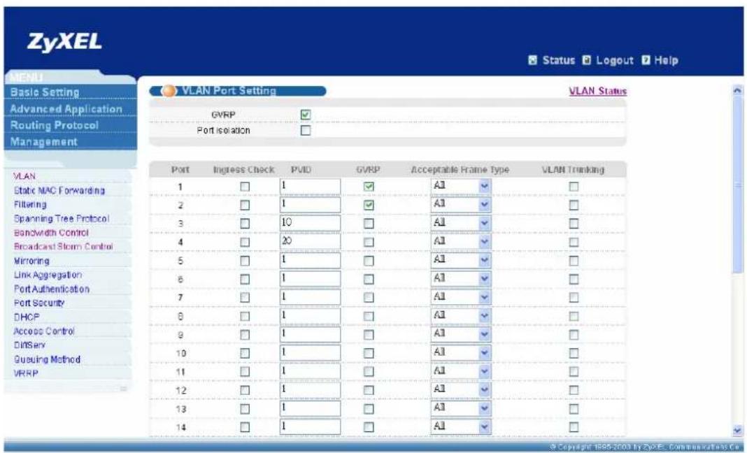
text_image
ZyXEL Status Logout Help VLAN Port Setting VLAN Status Basic Setting Advanced Application Routing Protocol Management GVRP Port isolation VLAN Static MAC Forwarding Filtering Spanning Tree Protocol Bandwidth Control Broadcast Storm Control Mirroring Link Aggregation Port Authentication Port Security DHCP Access Control DNServ Queuing Method VRRP Port Ingress Check PVID GVRP Acceptable Frame Type VLAN Trunking 1 1 ✓ A1 ✓ 2 1 ✓ A1 ✓ 3 10 ✓ A1 ✓ 4 20 ✓ A1 ✓ 5 1 ✓ A1 ✓ 6 1 ✓ A1 ✓ 7 1 ✓ A1 ✓ 8 1 ✓ A1 ✓ 9 1 ✓ A1 ✓ 10 1 ✓ A1 ✓ 11 1 ✓ A1 ✓ 12 1 ✓ A1 ✓ 13 1 ✓ A1 ✓ 14 1 ✓ A1 ✓ © Copyright 1985-2003 by ZyXEL Communications Co.2. For Switch B on Floor 1:
Please follow the same steps to adding VLAN 10: port 3, fixed, untag; port 23, fixed, Tx tagging; port 24, fixed, Tx tagging".
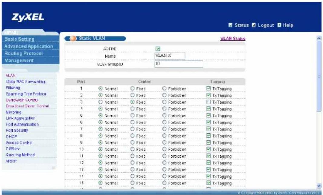
text_image
ZyXEL Status Logout Help MENU Static VLAN VLAN Status ACTIVE Name VLAN 10 VLAN Group ID 10 VLAN Static MAC Forwarding Filtering Spanning Tree Protocol Bandwidth Control Broadcast Storm Control Mirroring Link Aggregation Port Authentication Port Security DHCP Access Control Diffserv Queuing Method VRPP Port Control Tagging 1 Normal Fixed Forbidden Tx Tagging 2 Normal Fixed Forbidden Tx Tagging 3 Normal Fixed Forbidden Tx Tagging 4 Normal Fixed Forbidden Tx Tagging 5 Normal Fixed Forbidden Tx Tagging 6 Normal Fixed Forbidden Tx Tagging 7 Normal Fixed Forbidden Tx Tagging 8 Normal Fixed Forbidden Tx Tagging 9 Normal Fixed Forbidden Tx Tagging 10 Normal Fixed Forbidden Tx Tagging 11 Normal Fixed Forbidden Tx Tagging 12 Normal Fixed Forbidden Tx Tagging 13 Normal Fixed Forbidden Tx Tagging 14 Normal Fixed Forbidden Tx Tagging 15 Normal Fixed Forbidden Tx TaggingAdd VLAN 20 to this switch, VLAN 20: port 4, fixed, untag; port 23, fixed, Tx tagging; port 24, fixed, Tx tagging.

text_image
ZyXEL Status Logout Help Static VLAN VLAN Status ACTIVE Name VLAN 20 VLAN Group ID 20 Port Control Tagging 1 Normal Fixed Forbidden Tx Tagging 2 Normal Fixed Forbidden Tx Tagging 3 Normal Fixed Forbidden Tx Tagging 4 Normal Fixed Forbidden Tx Tagging 5 Normal Fixed Forbidden Tx Tagging 6 Normal Fixed Forbidden Tx Tagging 7 Normal Fixed Forbidden Tx Tagging 8 Normal Fixed Forbidden Tx Tagging 9 Normal Fixed Forbidden Tx Tagging 10 Normal Fixed Forbidden Tx Tagging 11 Normal Fixed Forbidden Tx Tagging 12 Normal Fixed Forbidden Tx Tagging 13 Normal Fixed Forbidden Tx Tagging 14 Normal Fixed Forbidden Tx Tagging 15 Normal Fixed Forbidden Tx Tagging © Copyright: 1985-2003 by ZyXEL Communications Co.Please click VLAN port setting to bring up the following screen, setup PVID 10 for port 3, PVID 20 for port 4, and enable GVRP on the top of the screen and port 1, port 2, port 23, port 24.

text_image
ZyXEL Status Logout Help VLAN Port Setting GVRP Port isolation VLAN Status 1 2 3 4 5 6 7 8 9 10 11 12 13 14 Ingress Check PVID GVRP Acceptable Frame Type VLAN Trunking A1 A1 A1 A1 A1 A1 A1 A1 A1 A1 A1 A1 A1 A1 A1 © Copyright 1985-2003 by ZyXEL Communications Co.3. For Switch C on Basement:
Please set static VLAN 10: port 23, fixed, untag.
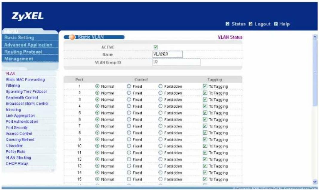
text_image
ZyXEL Status Logout Help MENU Basic Setting Advanced Application Routing Protocol Management Static VLAN VLAN Status ACTIVE Name VLANIO VLAN Group ID 10 Port Control Tagging 1 Normal Fixed Forbidden Tx Tagging 2 Normal Fixed Forbidden Tx Tagging 3 Normal Fixed Forbidden Tx Tagging 4 Normal Fixed Forbidden Tx Tagging 5 Normal Fixed Forbidden Tx Tagging 6 Normal Fixed Forbidden Tx Tagging 7 Normal Fixed Forbidden Tx Tagging 8 Normal Fixed Forbidden Tx Tagging 9 Normal Fixed Forbidden Tx Tagging 10 Normal Fixed Forbidden Tx Tagging 11 Normal Fixed Forbidden Tx Tagging 12 Normal Fixed Forbidden Tx Tagging 13 Normal Fixed Forbidden Tx Tagging 14 Normal Fixed Forbidden Tx Tagging 15 Normal Fixed Forbidden Tx TaggingPlease set static VLAN 20: port 23, fixed, untag.
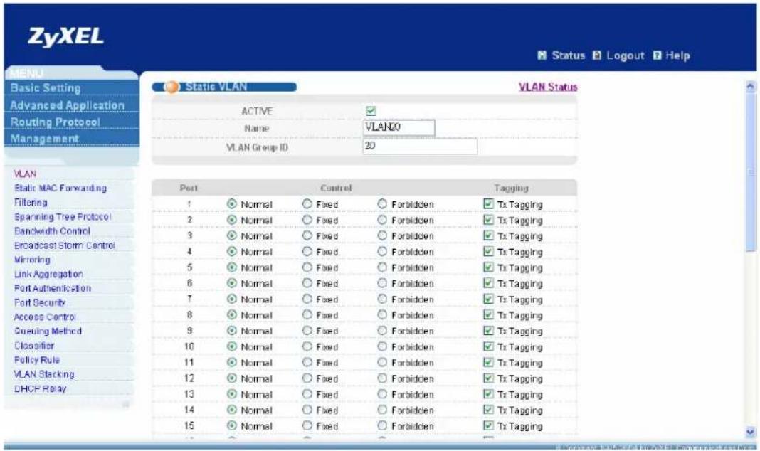
text_image
ZyXEL Status Logout Help MENU Static VLAN VLAN Status ACTIVE Name VLAN20 VLAN Group ID 20 VLAN Static MAC Forwarding Filtering Spanning Tree Protocol Bandwidth Control Broadcast Storm Control Mirroring Link Aggregation Port Authentication Port Security Access Control Queuing Method Classifier Policy Rule VLAN Stacking DHCP Relay Port Control Tagging 1 Normal Fixed Forbidden Tx Tagging 2 Normal Fixed Forbidden Tx Tagging 3 Normal Fixed Forbidden Tx Tagging 4 Normal Fixed Forbidden Tx Tagging 5 Normal Fixed Forbidden Tx Tagging 6 Normal Fixed Forbidden Tx Tagging 7 Normal Fixed Forbidden Tx Tagging 8 Normal Fixed Forbidden Tx Tagging 9 Normal Fixed Forbidden Tx Tagging 10 Normal Fixed Forbidden Tx Tagging 11 Normal Fixed Forbidden Tx Tagging 12 Normal Fixed Forbidden Tx Tagging 13 Normal Fixed Forbidden Tx Tagging 14 Normal Fixed Forbidden Tx Tagging 15 Normal Fixed Forbidden Tx TaggingPlease add VLAN 30: port 1, fixed, untag; port23, fixed, untag; port 24, fixed, Tx tagging.
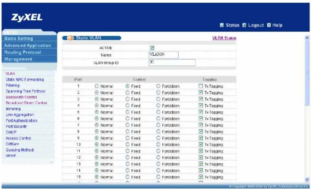
text_image
ZyXEL Status Logout Help MENU Basic Setting Advanced Application Routing Protocol Management Static VLAN VLAN Status ACTIVE ✓ Name VLAN30 VLAN Group ID 30 VLAN Static MAC Forwarding Filtering Spanning Tree Protocol Bandwidth Control Broadcast Storm Control Mirroring Link Aggregation Port Authentication Port Security DHCP Access Control Diffsay Queuing Method VRRP Port Control Tapping 1 ○ Normal ● Fixed ○ Forbidden □ Tx Tagging 2 ○ Normal ○ Fixed ○ Forbidden ✓ Tx Tagging 3 ○ Normal ○ Fixed ○ Forbidden ✓ Tx Tagging 4 ○ Normal ○ Fixed ○ Forbidden ✓ Tx Tagging 5 ○ Normal ○ Fixed ○ Forbidden ✓ Tx Tagging 6 ○ Normal ○ Fixed ○ Forbidden ✓ Tx Tagging 7 ○ Normal ○ Fixed ○ Forbidden ✓ Tx Tagging 8 ○ Normal ○ Fixed ○ Forbidden ✓ Tx Tagging 9 ○ Normal ○ Fixed ○ Forbidden ✓ Tx Tagging 10 ○ Normal ○ Fixed ○ Forbidden ✓ Tx Tagging 11 ○ Normal ○ Fixed ○ Forbidden ✓ Tx Tagging 12 ○ Normal ○ Fixed ○ Forbidden ✓ Tx Tagging 13 ○ Normal ○ Fixed ○ Forbidden ✓ Tx Tagging 14 ○ Normal ○ Fixed ○ Forbidden ✓ Tx Tagging 15 ○ Normal ○ Fixed ○ Forbidden ✓ Tx TaggingPlease setup PVID 30 for port 1 and enable GVRP on port 3 and port 24.

text_image
ZyXEL Status Logout Help MENU Basic Setting Advanced Application Routing Protocol Management VLAN Port Setting VLAN Status GVRP ✓ Port isolation ✓ VLAN 1 30 A1 ✓ 2 1 A1 ✓ 3 1 A1 ✓ 4 1 A1 ✓ 5 1 A1 ✓ 6 1 A1 ✓ 7 1 A1 ✓ 8 1 A1 ✓ 9 1 A1 ✓ 10 1 A1 ✓ 11 1 A1 ✓ 12 1 A1 ✓ 13 1 A1 ✓ 14 1 A1 ✓ © Copyright: 1998-2003 by ZyXEL Communications Co.Application Scenario C:
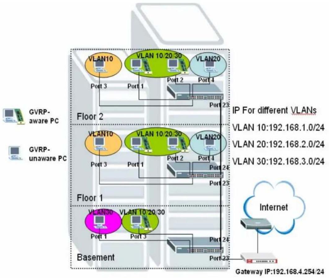
flowchart
graph TD
    subgraph_Floor_1["Floor 1"]
        A["VLAN30"] --> B["Port 1"]
        C["VLAN10 20 30"] --> D["Port 3"]
        E["VLAN10"] --> F["Port 1"]
        G["VLAN10 20 30"] --> H["Port 2"]
        I["VLAN20"] --> J["Port 4"]
        K["VLAN20 20 30"] --> L["Port 2"]
        M["VLAN10"] --> N["Port 3"]
        O["VLAN10 20 30"] --> P["Port 1"]
        Q["VLAN20"] --> R["Port 2"]
        S["VLAN20 20 30"] --> T["Port 4"]
        U["VLAN10"] --> V["Port 3"]
        W["VLAN10 20 30"] --> X["Port 1"]
        Y["VLAN20"] --> Z["Port 2"]
        AA["VLAN20 20 30"] --> AB["Port 4"]
        AC["VLAN10"] --> AD["Port 3"]
        AE["VLAN10 20 30"] --> AF["Port 1"]
        AG["VLAN20"] --> AH["Port 2"]
        AI["VLAN20 20 30"] --> AJ["Port 4"]
        AK["VLAN10"] --> AL["Port 3"]
        AM["VLAN10 20 30"] --> AN["Port 1"]
        AO["VLAN20"] --> AP["Port 4"]
        AQ["VLAN20 20 30"] --> AR["Port 2"]
        AS["VLAN10"] --> AT["Port 3"]
        AU["VLAN10 20 30"] --> AV["Port 1"]
        AW["VLAN20"] --> AX["Port 4"]
        AY["VLAN10"] --> AZ["Port 3"]
        BA["VLAN10 20 30"] --> BB["Port 1"]
        BC["VLAN20"] --> BD["Port 4"]
        BE["VLAN20 20 30"] --> BF["Port 2"]
    end
    subgraph Basement
        BG["VLAN30"] --> BH["Port 1"]
        BI["VLAN10 20 30"] --> BJ["Port 3"]
        BK["VLAN10 20 30"] --> BL["Port 1"]
        BM["VLAN20"] --> BN["Port 4"]
        BO["VLAN20 20 30"] --> BP["Port 1"]
        BQ["VLAN10"] --> BR["Port 3"]
        BS["VLAN10 20 30"] --> BT["Port 1"]
        BU["VLAN20"] --> BV["Port 4"]
        BW["VLAN20 20 30"] --> BX["Port 1"]
        BY["VLAN10"] --> BZ["Port 3"]
        CA["VLAN10 20 30"] --> CB["Port 1"]
        CC["VLAN20"] --> CD["Port 4"]
        DD["VLAN20 20 30"] --> DP["Port 1"]
        EQ["VLAN10"] --> RZ["Port 3"]
        DA["VLAN10 20 30"] --> DB["Port 1"]
        DC["VLAN20"] --> DDZ["Port 4"]
        EE["VLAN20 20 30"] --> FZ["Port 1"]
    end
    subgraph Gateway
        GA["Gateway IP:192.168.4.254/24"]
    end
    subgraph IP_Fractions
        HIP["IP For different VLANs"]
    end
Scenario Description:
Scenario C is for all clients can surf Internet or public resource when dividing multiple subnets for the same structure from scenario B. In this scenario, there are 3 subnets match to 3 VLANs to let network administrator manage VLAN more expediently: subnet 192.168.1.0/24 for VLAN 10; subnet 192.168.2.0/24 for VLAN 20; subnet 192.168.3.0/24 for VLAN 30. In order to control traffic routing between different subnets, we put a layer 3 switch (ES4024/ES4024A/GS4024) on basement. The configuration of switch A and switch B are the same as scenario B, only switch C need more configurations in this network environment.
How to configure this scenario:
- For Switch A on Floor 2:
Please enter VLAN setting under Advanced Application menu and click “static VLAN” to bring up the following screen, adding VLAN 10: port 3, fixed, untag; port 23, fixed, Tx tagging”.

text_image
ZyXEL Status Logout Help MENU Basic Setting Advanced Application Routing Protocol Management Static VLAN VLAN Status ACTIVE Name VLAN 10 VLAN Group ID 10 VLAN Static MAC Forwarding Filtering Spanning Tree Protocol Bandwidth Control Broadcast Storm Control Mirroring Link Aggregation Port Authentication Port Security DHCP Access Control Diffsay Queuing Method VRRP Port Control Tagging 1 Normal Fixed Forbidden Tx Tagging 2 Normal Fixed Forbidden Tx Tagging 3 Normal Fixed Forbidden Tx Tagging 4 Normal Fixed Forbidden Tx Tagging 5 Normal Fixed Forbidden Tx Tagging 6 Normal Fixed Forbidden Tx Tagging 7 Normal Fixed Forbidden Tx Tagging 8 Normal Fixed Forbidden Tx Tagging 9 Normal Fixed Forbidden Tx Tagging 10 Normal Fixed Forbidden Tx Tagging 11 Normal Fixed Forbidden Tx Tagging 12 Normal Fixed Forbidden Tx Tagging 13 Normal Fixed Forbidden Tx Tagging 14 Normal Fixed Forbidden Tx Tagging 15 Normal Fixed Forbidden Tx TaggingAdd VLAN 20 to this switch, VLAN 20: port 4, fixed, untag; port 23, fixed, Tx tagging.

text_image
ZyXEL Status Logout Help MENU Basic Setting Advanced Application Routing Protocol Management Static VLAN VLAN Status ACTIVE Name VLAN 20 VLAN Group ID 20 VLAN Static MAC Forwarding Filtering Spanning Tree Protocol Bandwidth Control Broadcast Storm Control Mirroring Link Aggregation Port Authentication Port Security DHCP Access Control DNServ Queuing Method VRRP Port Control Tagging 1 Normal Fixed Forbidden Tx Tagging 2 Normal Fixed Forbidden Tx Tagging 3 Normal Fixed Forbidden Tx Tagging 4 Normal Fixed Forbidden Tx Tagging 5 Normal Fixed Forbidden Tx Tagging 6 Normal Fixed Forbidden Tx Tagging 7 Normal Fixed Forbidden Tx Tagging 8 Normal Fixed Forbidden Tx Tagging 9 Normal Fixed Forbidden Tx Tagging 10 Normal Fixed Forbidden Tx Tagging 11 Normal Fixed Forbidden Tx Tagging 12 Normal Fixed Forbidden Tx Tagging 13 Normal Fixed Forbidden Tx Tagging 14 Normal Fixed Forbidden Tx Tagging 15 Normal Fixed Forbidden Tx TaggingPlease click VLAN port setting to bring up the following screen, setup PVID 10 for port 3, PVID 20 for port 4, and enable GVRP on the top of the screen and port 1, port 2, port 23.

text_image
ZyXEL Status Logout Help VLAN Port Setting VLAN Status Basic Setting Advanced Application Routing Protocol Management GVRP Port isolation VLAN Static MAC Forwarding Filtering Spanning Tree Protocol Bandwidth Control Broadcast Storm Control Mirroring Link Aggregation Port Authentication Port Security DHCP Access Control DNServ Queuing Method VRRP Port Ingress Check PVID GVRP Acceptable Frame Type VLAN Trunking 1 1 ✓ A1 ✓ 2 1 ✓ A1 ✓ 3 10 ✓ A1 ✓ 4 20 ✓ A1 ✓ 5 1 ✓ A1 ✓ 6 1 ✓ A1 ✓ 7 1 ✓ A1 ✓ 8 1 ✓ A1 ✓ 9 1 ✓ A1 ✓ 10 1 ✓ A1 ✓ 11 1 ✓ A1 ✓ 12 1 ✓ A1 ✓ 13 1 ✓ A1 ✓ 14 1 ✓ A1 ✓ © Copyright 1985-2003 by ZyXEL Communications Co.2. For Switch B on Floor 1:
Please follow the same steps to adding VLAN 10: port 3, fixed, untag; port 23, fixed, Tx tagging; port 24, fixed, Tx tagging".

text_image
ZyXEL Status Logout Help MENU Static VLAN VLAN Status ACTIVE Name VLAN 10 VLAN Group ID 10 VLAN Static MAC Forwarding Filtering Spanning Tree Protocol Bandwidth Control Broadcast Storm Control Mirroring Link Aggregation Port Authentication Port Security DHCP Access Control Diffserv Queuing Method VRPP Port Control Tagging 1 Normal Fixed Forbidden Tx Tagging 2 Normal Fixed Forbidden Tx Tagging 3 Normal Fixed Forbidden Tx Tagging 4 Normal Fixed Forbidden Tx Tagging 5 Normal Fixed Forbidden Tx Tagging 6 Normal Fixed Forbidden Tx Tagging 7 Normal Fixed Forbidden Tx Tagging 8 Normal Fixed Forbidden Tx Tagging 9 Normal Fixed Forbidden Tx Tagging 10 Normal Fixed Forbidden Tx Tagging 11 Normal Fixed Forbidden Tx Tagging 12 Normal Fixed Forbidden Tx Tagging 13 Normal Fixed Forbidden Tx Tagging 14 Normal Fixed Forbidden Tx Tagging 15 Normal Fixed Forbidden Tx TaggingAdd VLAN 20 to this switch, VLAN 20: port 4, fixed, untag; port 23, fixed, Tx tagging; port 24, fixed, Tx tagging.

text_image
ZyXEL Status Logout Help Static VLAN VLAN Status ACTIVE Name VLAN 20 VLAN Group ID 20 Port Control Tagging 1 Normal Fixed Forbidden Tx Tagging 2 Normal Fixed Forbidden Tx Tagging 3 Normal Fixed Forbidden Tx Tagging 4 Normal Fixed Forbidden Tx Tagging 5 Normal Fixed Forbidden Tx Tagging 6 Normal Fixed Forbidden Tx Tagging 7 Normal Fixed Forbidden Tx Tagging 8 Normal Fixed Forbidden Tx Tagging 9 Normal Fixed Forbidden Tx Tagging 10 Normal Fixed Forbidden Tx Tagging 11 Normal Fixed Forbidden Tx Tagging 12 Normal Fixed Forbidden Tx Tagging 13 Normal Fixed Forbidden Tx Tagging 14 Normal Fixed Forbidden Tx Tagging 15 Normal Fixed Forbidden Tx Tagging © Copyright: 1985-2003 by ZyXEL Communications Co.Please click VLAN port setting to bring up the following screen, setup PVID 10 for port 3, PVID 20 for port 4, and enable GVRP on the top of the screen and port 1, port2, port 23, port 24.

text_image
ZyXEL Status Logout Help VLAN Port Setting GVRP Port isolation VLAN Status 1 2 3 4 5 6 7 8 9 10 11 12 13 14 Ingress Check PVID GVRP Acceptable Frame Type VLAN Trunking A1 A1 A1 A1 A1 A1 A1 A1 A1 A1 A1 A1 A1 A1 A1 © Copyright 1985-2003 by ZyXEL Communications Co.- For Switch C (layer 3 switch) on Basement:
Please add VLAN 30: port 1, fixed, untag; port 24, fixed, Tx tagging.

text_image
ZyXEL Status Logout Help MENU Basic Setting Advanced Application Routing Protocol Management Static VLAN VLAN Status ACTIVE ✓ Name VLAN30 VLAN Group ID 30 VLAN Static MAC Forwarding Filtering Spanning Tree Protocol Bandwidth Control Broadcast Storm Control Mirroring Link Aggregation Port Authentication Port Security DHCP Access Control Diffserv Queuing Method VRRP Port Control Tapping 1 Normal Fixed Forbidden Tx Tagging 2 Normal Fixed Forbidden Tx Tagging 3 Normal Fixed Forbidden Tx Tagging 4 Normal Fixed Forbidden Tx Tagging 5 Normal Fixed Forbidden Tx Tagging 6 Normal Fixed Forbidden Tx Tagging 7 Normal Fixed Forbidden Tx Tagging 8 Normal Fixed Forbidden Tx Tagging 9 Normal Fixed Forbidden Tx Tagging 10 Normal Fixed Forbidden Tx Tagging 11 Normal Fixed Forbidden Tx Tagging 12 Normal Fixed Forbidden Tx Tagging 13 Normal Fixed Forbidden Tx Tagging 14 Normal Fixed Forbidden Tx Tagging 15 Normal Fixed Forbidden Tx Tagging © Copyright: 1885-2003 By ZyXEL Communications Co.Please setup PVID 30 for port 1 and enable GVRP on port 3 and port 24.
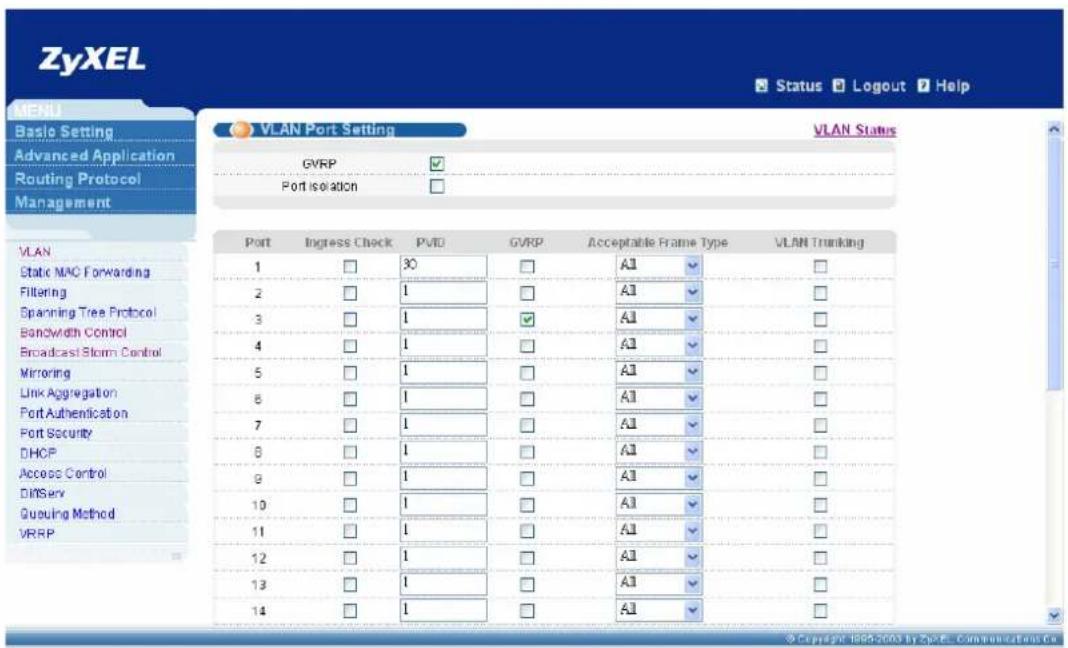
text_image
ZyXEL Status Logout Help MENU Basic Setting Advanced Application Routing Protocol Management VLAN Port Setting VLAN Status GVRP ✓ Port isolation ✓ VLAN 1 30 A1 ✓ 2 1 A1 ✓ 3 1 A1 ✓ 4 1 A1 ✓ 5 1 A1 ✓ 6 1 A1 ✓ 7 1 A1 ✓ 8 1 A1 ✓ 9 1 A1 ✓ 10 1 A1 ✓ 11 1 A1 ✓ 12 1 A1 ✓ 13 1 A1 ✓ 14 1 A1 ✓ 30 ✓ ✓ ✓ ✓ ✓ ✓ ✓ ✓ ✓ ✓ ✓ ✓ ✓ ✓ ✓ ✓ ✓ ✓ ✓ ✓ ✓ ✓ ✓ ✓ ✓ ✓ ✓ ✓ ✓ ✓ ✓ ✓ ✓ ✓ ✓ ✓ ✓ ✓ ✓ ✓ ✓ ✓ ✓ ✓ ✓ ✓ ✓ ✓ ✓ ✓Copyright 1998-2003 by ZpRPL Communications Co
Please click "IP setup", then setup 4 domains on ES4024/GS4024:
| Index IP address IP Subnet mask | VLAN ID | ||
| 1 | 192.168.1.0 | 255.255.255.0 | 10 |
| 2 | 192.168.2.0 | 255.255.255.0 | 20 |
| 3 | 192.168.3.0 | 255.255.255.0 | 30 |
| 4 | 192.168.4.0 | 255.255.255.0 | 1 |

text_image
ZyXEL Status Logout Help IP Setup Default Gateway 192.168.1.254 Domain Name Server 000.0 Apply Cancel IP Address 192.168.1.1 IP Subnet Mask 255.255.255.0 VID 10 Add Cancel Index IP Address IP Subnet Mask VID Delete 1 192.168.4.1 255.255.255.0 1 Delete Cancel © Copyright-1985-2003 by ZyXEL Communications Co.After finish domain setting, please change the default gateway and domain name server setting and click "Apply".
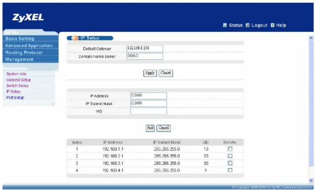
text_image
ZyXEL Status Logout Help IP Setup Default Gateway 192.168.4.254 Domain Name Server 000.0 Apply Cancel IP Address 0.000 IP Subnet Mask 0.000 VID Add Cancel Index IP Address IP Subnet Mask VID Delete 1 192.168.1.1 255.255 255.0 10 □ 2 192.168.2.1 255.255 255.0 20 □ 3 192.168.3.1 255.255 255.0 30 □ 4 192.168.4.1 255.255 255.0 1 □Please click “Filtering” under “Advanced Application” menu list to bring up the following screen and add 3 filter rules to block traffic from different subnets.
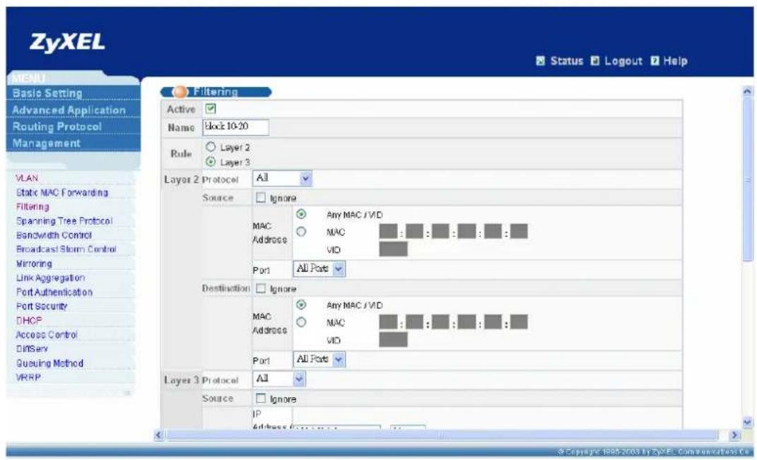
text_image
ZyXEL Status Logout Help MENU Basic Setting Advanced Application Routing Protocol Management Filtering Active Name Block 10-20 Rule Layer 2 Layer 3 Layer 2 Protocol All Source Ignore MAC Any MAC / VID Address MAC VID Port All Ports Destination Ignore MAC Any MAC / VID Address MAC VID Port All Ports Layer 3 Protocol All Source Ignore IP Address Function © Copyright 1985-2003 by ZyXEL Communications Co.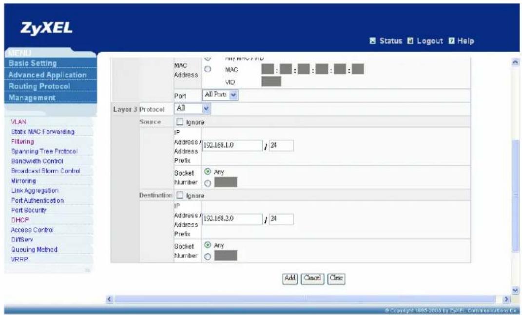
text_image
ZyXEL Status Logout Help MAC Address MAC VID Port All Ports Layer 3 Protocol All Source Ignore IP Address / Address / Prefix 192.168.1.0 / 24 Socket Any Number Destination Ignore IP Address / Address / Prefix 192.168.2.0 / 24 Socket Any Number Add Cancel Close Basic Setting Advanced Application Routing Protocol Management VLAN Static MAC Forwarding Filtering Spanning Tree Protocol Bandwidth Control Broadcast Storm Control Mirroring Link Aggregation Port Authentication Port Security DHCP Access Control DINServ Queuing Method VRRP.You will see the following screen after finish filtering setting.
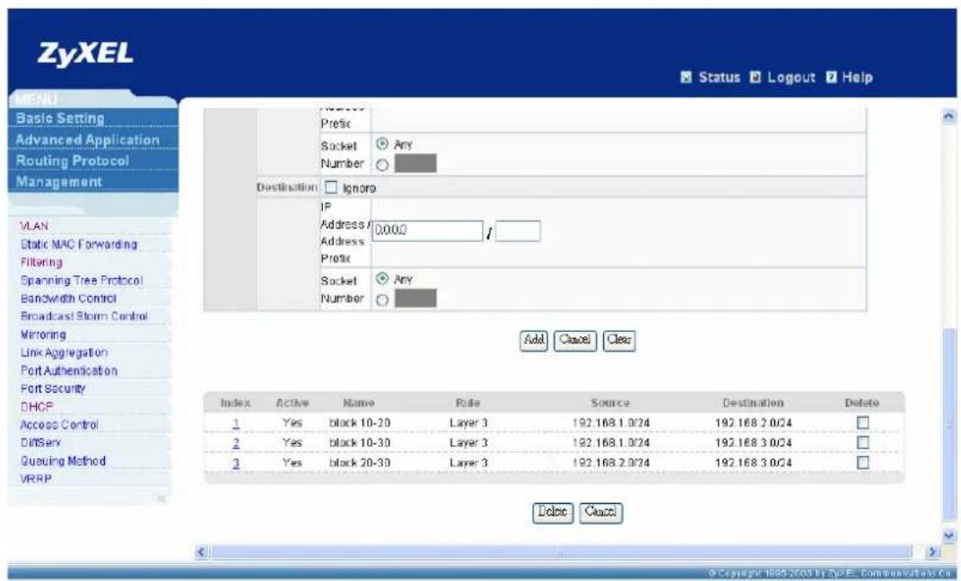
text_image
ZyXEL Status Logout Help MENU Basic Setting Advanced Application Routing Protocol Management Number Prefix Socket Any Number Destination Ignore IP Address 0.000 Address 1 Prefix Socket Any Number Add Cancel Clear Index Active Name Rule Source Destination Delete 1 Yes black 10-20 Layer 3 192.168.1.0/24 192.168.2.0/24 2 Yes black 10-30 Layer 3 192.168.1.0/24 192.168.3.0/24 3 Yes black 20-30 Layer 3 192.168.2.0/24 192.168.3.0/24 Delete Cancel Access Control Diffserv Queuing Method VRRP © Copyright: 1985-2003 by ZyxEL Communications Co.Advise:
- Please also configure routing protocol to make layer 3 Switch and gateway exchange their routing information in this scenario.
- You can also enable DHCP feature based on VID on layer 3 Switch (ES4024/GS4024), which will help you to dynamically assign IP to different VLANs more expediently.
FAQ
What is the maximum line rate of IES1248?
It can support ADSL2+, so line rate can reach to 1.2Mbps in upstream direction and 25 Mbps in downstream in a short distance.
How many management instances can access IES-1248 at the same time?
Only one console, one WEB GUI and four telnet accounts can access IES at the same time.
What is the difference between IES1248-71 and IES1248-73?
• IES1248-71 : ADSL Annex A for POTS.
• IES1248-73 : ADSL Annex B for ISDN.
What is the power requirement of IES- 1248?
• Power Input is -48VDC(-36\~-72VDC).
• Maximum power consumption is 90W.
What kind of the DSL standard does IES1248 compliant?
- ADSL : G.992.1, G.992.2, T1.413 issue 2, G.lite
• ADSL 2 : G.992.3, G.992.4 - ADSL 2+ : G.992.5.
What is the ADSL chipset of IES1248?
Centillium Maximus
What is the Network Processor of IES1248?
Wintegra's WinPath787D4
How many Flash memory and SDRAM that IES 1248 supports?
- Flash memory : 4Mbytes
- SDRAM : 64Mbytes
What kind of the features that IES 1248 supports?
• RFC 2684 Bridge Mode (Replace RFC 1483)
- IEEE 802.1Q
• VLAN acceptable frame type filter
- IGMPv2 Snooping
• ATM QoS (UBR, CBR, VBR) per PVC
• DHCP Relay Agent Information Option 82.
- MAC Filter
• MAC Count Filter (Limit the numbers of MAC address)
- Packet Type Filter
- IEEE 802.1x Port-based Network Access Control
- ADSL Port Isolation
- Multiple PVCs
- Support VC profile
What is the default console rate of IES1248?
9600, 8bit data, no parity, stop bit=1, no flow control.
How many static VLAN entries can IES1248 support?
IES1248 supports up to 1024 VLAN entries..
How many VLANs can each ADSL port of IES1248 join?
Each ADSL port can join at most 16 VLANs.
How many VLANs can each ADSL port of IES1248 join?
Each ADSL port can join at most 16 VLANs.
What kinds of profiles can IES1248 supprot?
▶ Number of VLAN: 1024
➢ ADSL profile: 96
▶ ATM profile: 48
IGMP filter profile: 128
➢ ADSL ALARM profile: 8
▶ Dot1X profile: 64
▶ DHCP relay server: 32
IP ROUTE: 128
➢ Static multicast address: 32
▶ Igmp groups: 512 groups
MAC learning: 14k (128 per ADSL port, 4k per ENET port)
▶ RPVC gateway IP address: 96
Trouble Shooting
If my computer can't access the DSLAM by WEB/Telnet/Ping from Ethernet port, only console screen can access successfully, what can I do?
- Make sure that the Ethernet port has the appropriate speed mode setting.
-
Please check the Ethernet cable and connections between Ethernet port and PC, make sure the Ethernet LED is on when cable connection is already.
-
Make sure that both inband and outband IP of IES and Your PC are properly configured.
-
Please check Security host IP and service port setting from console port. Only the PC configured with IP of secured host has the authority to access the IPDSLAM. Please enter console screen via HyperTerminal by mini RJ-11 cable.
a) IES-1000
Please enter "sys" under "sys" submenu. Then key in "secured host" to check Security Host state.
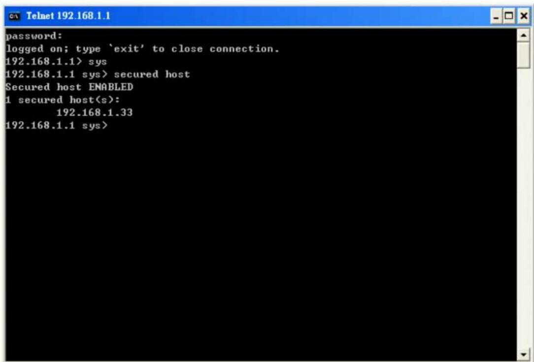
text_image
password: logged on; type 'exit' to close connection. 192.168.1.1> sys 192.168.1.1 sys> secured host Secured host ENABLED 1 secured host(s): 192.168.1.33 192.168.1.1 sys>b) IES2000/3000 & IES 1248
Please key in “sys client show” to check security host IP to see your PC is included in the list or not.
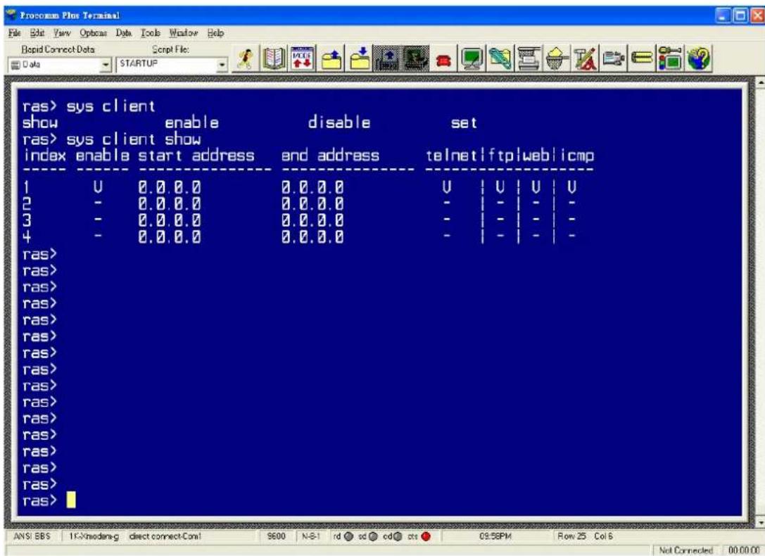
text_image
ras> sys client show enable disable set ras> sys client show index enable start address end address telnetlftplweblicmp 1 U 0.0 0.0 0.0.0.0 U | U | U | U 2 - 0.0 0.0 0.0.0.0 - | - | - | - 3 - 0.0 0.0 0.0.0.0 - | - | - | - 4 - 0.0 0.0 0.0.0.0 - | - | - | - ras> ras> ras> ras> ras> ras> ras> ras> ras> ras> ras> ras> ras> ras> ras> ras> ras> ras> ANS: EBS 1K-Modem-g direct connect-Com! 9600 N-B1 rd sc cd# cs 09:58PM Row 25 Col 8 Not Connected 00:00:00Please key in “sys server show” to check server port, make sure that your application follow the server port in the list shown.
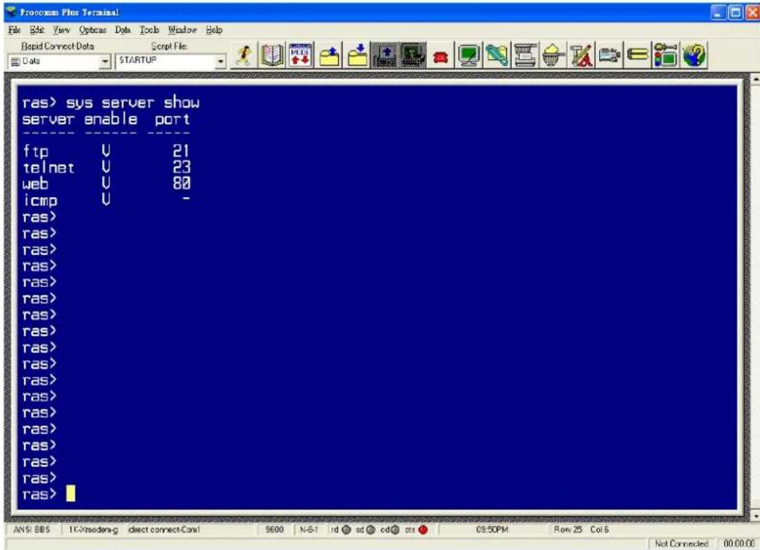
text_image
ras> sys server show server enable port ---- ---- ---- ftp U 21 telnet U 23 web U 80 icmp U - ras> ras> ras> ras> ras> ras> ras> ras> ras> ras> ras> ras> ras> ras> ras> ras> ras> ras> ras> ras> ras> ras> ras> ras> ras> 7 ANS: BBS 1K-Modem-g direct connect-Con1 S600 N-S-1 rd sd cd# cts 09:50PM Row 25 Col 5 Not Connected 00:00:00- Please check VLAN configuration, make sure that traffic from outside is tagged or
will be added with CPU VLAN ID when access the IES.
- please check your topology if you are not connect PC or device to IES directly.
If DHCP Relay Option 82 can't work, for example, PC can not get desired IP address from DHCP server, what can I do?
- Please check your VLAN configuration on IES, make sure that IES can reach DHCP server.
- Please check your DHCP option 82 description configuration, make sure that description information is match to your DHCP server setting; otherwise DHCP server won't assign any IP from its IP pool to an invalid DHCP request.
- Please make sure that your DHCP server support DHCP option 82, and check your configuration on DHCP server are all correct.
- Please check your DHCP client, make sure that it is working on “obtain an IP address automatically” normally.
How to reset this device as factory default?
a) IES1000
Upload the default file to IES1000 by ftp, web. Or upload the bin file by BOOTP/TFTP.
ftp:
Please ftp into the DSLAM. Replace the "init" with the default rom file by put command.
-rw-rw-rw- 1 owner group 68 Jul 01 12:00 snmp.dat
-rw-rw-rw- 1 owner group 68 Jul 01 12:00 initdot1x
-rw-rw-rw- 1 owner group 627 Jul 01 12:00 allinfo
-rw-rw-rw- 1 owner group 3397 Jul 01 12:00 init
--w--w--w- 1 owner group 1325148 Jul 01 12:00 image
226 File sent OK
ftp: 1592 bytes received in 0.01Seconds 159.20Kbytes/sec.
ftp> put 205DD0C0.rom init
WEB:
Please open Maintenance page. Click “Restore Configuration” link.
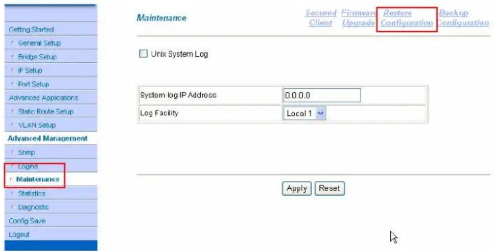
text_image
Getting Started General Setup Bridge Setup IP Setup Port Setup Advanced Applications Static Route Setup VLAN Setup Advanced Management Snmp Logins Maintenance Statistics Diagnostic Config Save Logout Maintenance Secured Client Firmware Upgrade Restore Configuration Backup Configuration Unix System Log System log IP Address 0.0.0.0 Log Facility Local 1 Apply ResetPress Browse button to select the default rom file. Then press "Upload" button.

text_image
Restore Configuration To restore the device's configuration from a file, browse to the location of the configuration file and click Upload. File Path : 205DD0C0\205DD0C0.rom | 割覧... Advanced Management Snmp Logins Maintenance Statistics Diagnostic Config Save Logout Uploadb) IES2000/3000
Upload default rom file to IES2000/3000 by ftp, web or console
Console:
When the system reboots, press any key within 3 seconds to enter debug mode.
Bootbase Version: V1.02(MSC1000) | 09/26/2002 13:15:56
RAM: Size = 32768 Kbytes
FLASH: Intel 32M

ZyNOS Version: V3.50(DS.6) | 04/21/2004 12:35:23
"Press any key to enter debug mode within 3 seconds."
......
Enter Debug Mode

MSC 1000>
Suggest changing it to 115,200 temporarily to speed up speed by "atba5" command.
MSC 1000> atba5
Now, console speed will be changed to 115200 bps
Take "atlc" command to restore the default configuration file.
MSC 1000> atlc
Starting XMODEM upload (CRC mode)....
CCCC ← Send file to MSC via 1K-Xmodem when see this message.
When you see "cccc...", please send the default rom file to MSC via 1k-Xmodem or Xmodem. See following two figures.
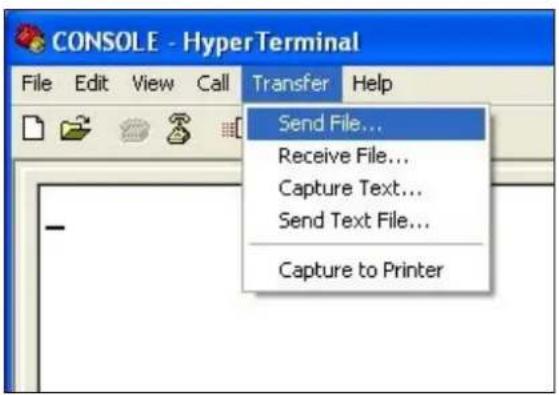
text_image
CONSOLE - HyperTerminal File Edit View Call Transfer Help Send File... Receive File... Capture Text... Send Text File... Capture to Printer
text_image
Send File Folder: C:\Documents and Settings\yslin Filename: Browse... Protocol: 1K Xmodem Send Close CancelWEB:
Please open Maintenance page. Click "Restore Configuration" link.
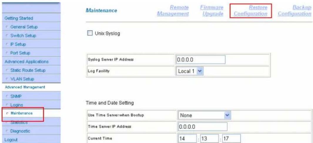
text_image
Getting Started General Setup Switch Setup IP Setup Port Setup Advanced Applications Static Route Setup VLAN Setup Advanced Management SNMP Logins Maintenance Statistics Diagnostic Logout Maintenance Remote Management Firmware Upgrade Restore Configuration Backup Configuration Unix Syslog Syslog Server IP Address 0.0.0.0 Log Facility Local 1 Time and Date Setting Use Time Server when Bootup None Time Server IP Address 0.0.0.0 Current Time 14 : 13 : 17Press Browse button to select the default rom file. Then press the "Restore" button.

text_image
Restore Configuration Getting Started General Setup Switch Setup IP Setup Port Setup Advanced Applications Static Route Setup VLAN Setup Advanced Management SNMP Logins Maintenance Statistics Diagnostic Logout To restore the device's configuration from a file, browse to the location of the configuration file and click Restore button. File Path : e:\360ds1c0\360ds1c0.rom 浏览... Restoreftp:
Please ftp into the DSLAM. Replace the rom-0 with the default rom file by put command.

text_image
--w--w--w- 1 owner group 0 Jul 01 12:00 fw-13 --w--w--w- 1 owner group 0 Jul 01 12:00 fw-14 --w--w--w- 1 owner group 0 Jul 01 12:00 fw-15 --w--w--w- 1 owner group 0 Jul 01 12:00 fw-16 226 File sent OK ftp: 1246 bytes received in 0.00Seconds 1246000.00Kbytes/sec. ftp> put 360ds1c0.rom rom-0c) IES1248
You can set the factory default by CLI command or WEB
WEB:
Please open Maintenance Page. Click the "Restore Default Configuration" link.
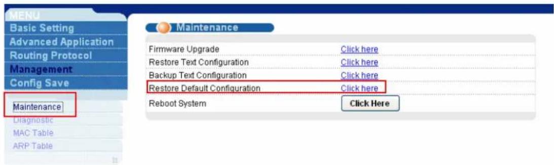
text_image
MENU Basic Setting Advanced Application Routing Protocol Management Config Save Maintenance Diagnostic MAC Table ARP Table Maintenance Firmware Upgrade Click here Restore Text Configuration Click here Backup Text Configuration Click here Restore Default Configuration Click here Reboot System Click HereIt will pop up a dialog to ask for your confirmation. Please click "Ok" button.

text_image
Maintenance Firmware Upgrade Click here Restore Text Configuration Click here Backup Text Configuration Click here Restore Default Configuration Click here Reboot System Click here Microsoft Internet Explorer Restore default configurations and reboot the system? 確定 取消Console/telnet:
You can enter the CLI command mode by console or telnet. Type "config restore" to restore the default settings. Then it will ask for your confirmation. Type "Y" to start
restoring.
| Copyright (c) Alcatel Communications Corp. | |||
| ras> help | |||
| #ys | adsl | switch | ip |
| statistics | config | exit | chsh |
| engshcmd | debug | ||
| ras> sys | |||
| info | passwd | reboot | snmp |
| server | client | syslog | time |
| date | timeserver | log | wdog |
| monitor | chsh | showall | |
| ras> config | |||
| show | save | restore | |
| ras> config restore | |||
| System will reboot automatically after restoring default configuration. Do you want to proceed(y/n)? > | |||
xDSL link fail?
- Check if the DSL port is enabled.
- Check if the cable is plugged well.
- For ADSL, check the ADSL modem and line card are in the same mode (Annex A or Annex B).
- For G.SHDSL, check the modem and line card use the same PSD(Annex A or Annex B).
- For G.SHDSL, check if the modem is in remote mode.
- Check if the distance is too long. Actually, we don't suggest the distance between CO and CPE is more than 4Km. Of course, it depends on your real line quality. To verify this, you can replace the original cable with a shorter one.
- Set the smaller value in MIN rate to check if the MIN rate is too high.
- Change the Cable.
- Change the CPE.
- Change the DSL port.
- Change the line card.
If above procedures can't resolve the link fail issue, please call RMA.
Which new version I should upgrade?
Please link to http://www.zyxel.com/support/fwlib.php web site. Select the Product Category and Model Name of your device to search the latest firmware. Or you can select the Keyword to search that.
I forgot the Password, how do I recover it?
a.) IES-1000
Please use the BOOTP/TFTP and bin file to recover the configuration to factory default. Please refer to IES-1000's user manual to see the recovery procedure within Chapter 36.2 'BOOTP/TFTP Firmware Recovery of the Network'. All of your former configurations will recover to factory default. The default password is 1234.
b.) IES-2000/3000/1248
The only solution is to reset the password to default '1234' by resetting the whole IES-2000/3000/1248 configurations. To reset the settings you need to upload our default configuration file (*.rom). Please read through the following steps to do it.
- Connect your IES-2000/3000/1248 console port to PC's serial port.
- Start a Terminal program with 9600bps, N/8/1 settings.
- Power on the router you should see the power up message on the Terminal screen.
- Enter 'Debug Mode' during the device power on.
- Type 'atsh' to check the current firmware version.
- Download the above firmware *.zip from our FTP site or ask it from the local distributor if it is not on our Web/FTP.
- Extract the *.rom file in the zip to your hard disk.
- Type 'atlc' command in debug mode to start to upload the *.rom file.
- To send file, please select the file transfer function in terminal program to start it.
- Use X-Modem as protocol to send file.
- Enter 'atgo' to start up the IES-2000/3000/1248.
I can not access the DSLAM via console port. What should I do?
- Double check if the baud rate is correct, by default, the baud rate on ZyXEL IP DSLAM is 9600 N/8/1.
- Check if the Console cable is RS-232 standard using DB9 connectors, but not
null-modem cable.
- Check if the Console is damaged; if possible, try to change another one to give a try.
- Try to use the other Terminal software tool to see if it's a Terminal software issue.
There is no traffic could be transmitted through the DSLAM, what should I do?
- Check if the ADSL physical link is UP.
- Check if the port on DSLAM have been enabled.
- Check the VPI/VCI and Encapsulation are correct.
- Use OAM loopback test to check the ATM layer is ok.
- Check the Filter table's settings(MAC filter/Packet filter)
- Customer's IP address settings are correct.
- Check if the Port Isolation mechanism has been enabled on the DSALM.
- Check if there is any limitation on port MAC counter of the DSLAM.
- Check the VLAN setting including PVID, VLAN group and Egress settings.
Alarm Led is always on, what should I do?
- Please check the HW monitor to see what happened.
- For IES-3000, you need dual power supply for the device.