Orlando SLORLAWBSWA - Bed Shangri-La - Free user manual and instructions
Find the device manual for free Orlando SLORLAWBSWA Shangri-La in PDF.

User questions about Orlando SLORLAWBSWA Shangri-La
0 question about this device. Answer the ones you know or ask your own.
Ask a new question about this device
Download the instructions for your Bed in PDF format for free! Find your manual Orlando SLORLAWBSWA - Shangri-La and take your electronic device back in hand. On this page are published all the documents necessary for the use of your device. Orlando SLORLAWBSWA by Shangri-La.
USER MANUAL Orlando SLORLAWBSWA Shangri-La
natural_image
Line drawing of a wooden table with slatted panels and four legs (no text or symbols)ORLANDO WOOD BED
SINGLE
SLORLAWBSNA, SLORLAWBSWA
COMPONENTS
text_image
Technical diagram of a multi-layered electronic component with numbered parts and a fan base, likely for assembly or manufacturing purposes.Hardware

A Ú4Û
B (x8)

C (x8)
D (x8)

E (x8)
F (x8)

G (x1)
J (x52)

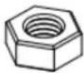
N (x6)
ASSEMBLY
Step 1: Secure A into the middle hole either side of part 1.
Repeat this process with the remaining part labelled 1. This will create two end assemblies.
Note:
Do not use power tools to assemble this bed as it may damage the components.

A (x4)

text_image
A 1 Ax2
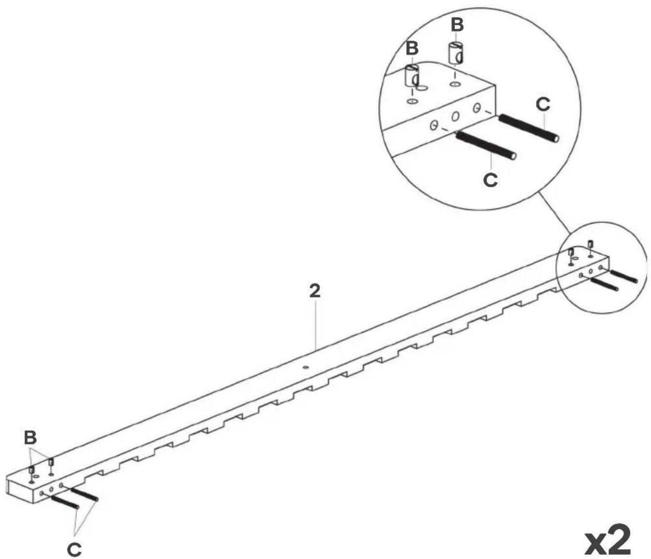
Step 2: Ensuring the hole on B is facing outward, secure B into one part labelled 2. Insert C into B as shown below.
Repeat this process with the remaining part labelled 2. This will create two side assemblies.
B (x8)

C (x8)
text_image
B C 2 x2x2
Step 3: Align the holes on end assemblies and connect them to the side assemblies. This will result in C to protrude through the holes on the top of the side assemblies.
Inside one top hole, insert D, E and F over C. Using the G wrench, tighten F to secure into place. Repeat this process with the remaining seven top holes.
D (x8)
E (x8)

F (x8)

G (x1)

text_image
Technical diagram of a mechanical assembly with labeled components and cross-sectional viewsx8
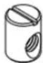
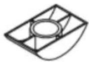
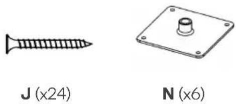
Step 4: Ensuring N is facing down, align and insert N into the holes shown in the example below. Using a Phillips screwdriver (not supplied), secure N with J screws.
natural_image
Two technical illustrations: a screw and a plate with a knob, both labeled with magnified views (no text or symbols on the objects themselves)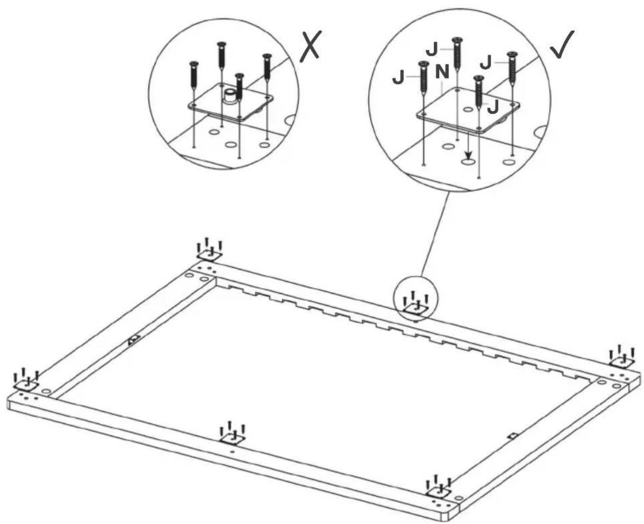
text_image
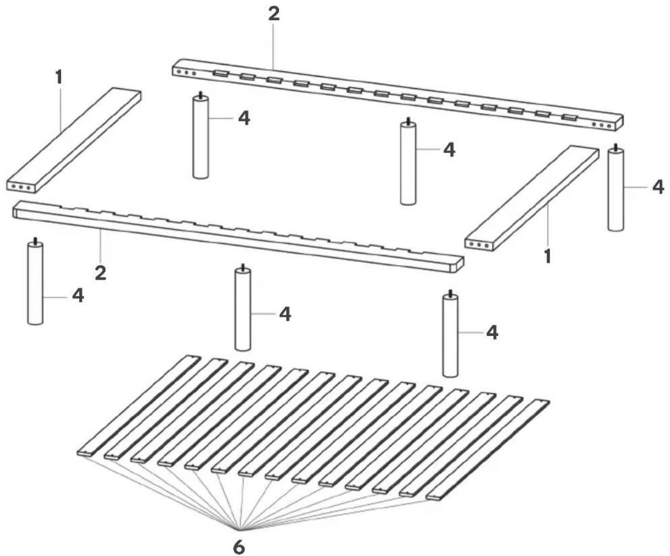
Technical diagram showing a 3D panel assembly with labeled components and cross-sectional views (X, √)Step 5: Twist and secure parts labelled 4 onto the side and end assemblies as shown below.

text_image
Technical diagram of a mechanical assembly with multiple 4-pin cylindrical components mounted on a rectangular frame.Step 6: Using a Phillips screwdriver (not supplied), secure parts labelled 6 onto the bed with J screws.

text_image
J (x28) 6 J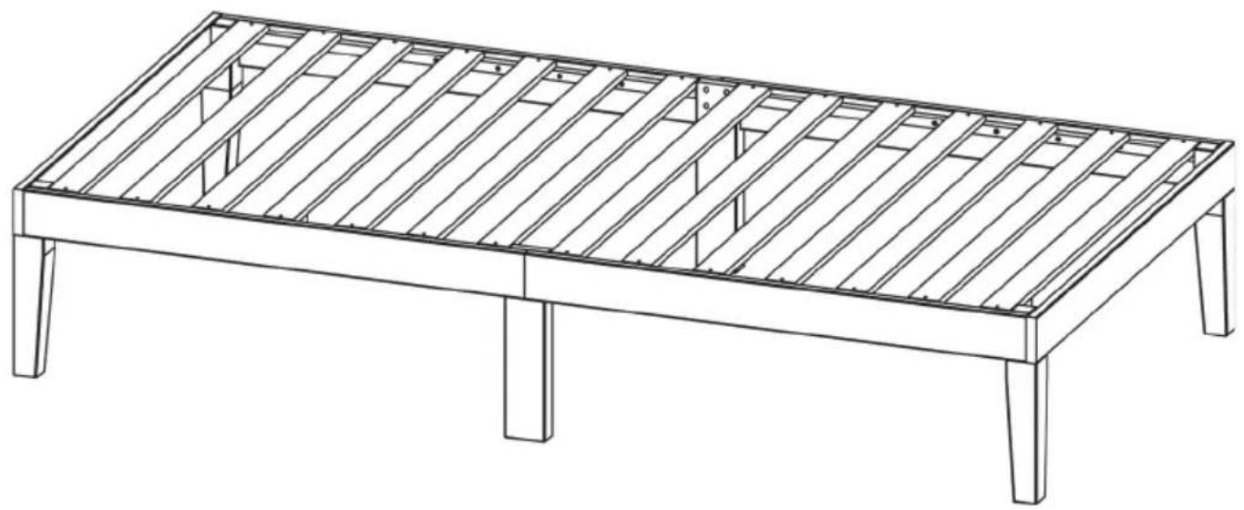
natural_image
Line drawing of a wooden table frame with slatted sides and legs (no text or symbols)Assembly complete.
NOTES
Need more information?
We hope that this user guide has given you the assistance needed for a simple set-up.
For the most up-to-date guide for your product, as well as any additional assistance you may require, head online to help.kogan.com
kogan.com