CPSPV3000ETL-S - Solar panel CyberPower - Free user manual and instructions
Find the device manual for free CPSPV3000ETL-S CyberPower in PDF.

User questions about CPSPV3000ETL-S CyberPower
0 question about this device. Answer the ones you know or ask your own.
Ask a new question about this device
Download the instructions for your Solar panel in PDF format for free! Find your manual CPSPV3000ETL-S - CyberPower and take your electronic device back in hand. On this page are published all the documents necessary for the use of your device. CPSPV3000ETL-S by CyberPower.
USER MANUAL CPSPV3000ETL-S CyberPower
CyberPower® Reliability Quality Valve
Reliability. Quality. Value.
text_image
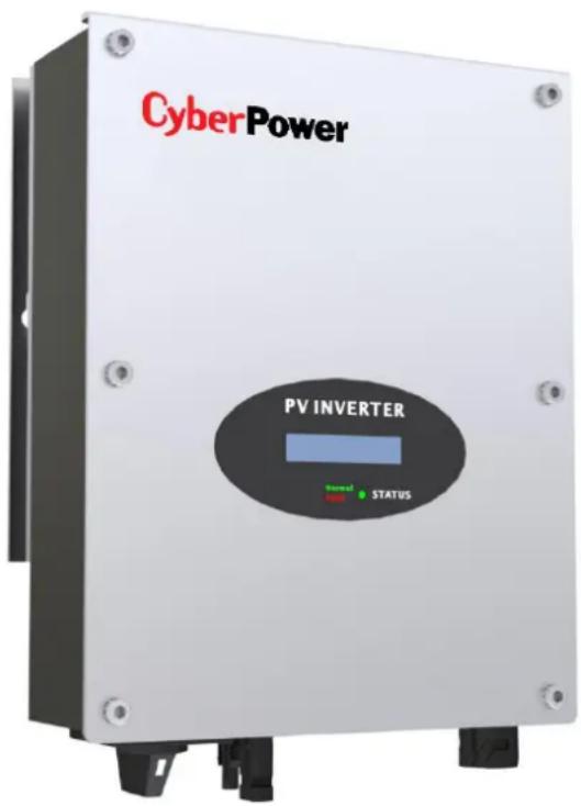
CyberPower PV INVERTER Signal STATUSUser's Manual
CPSPV3000ETL-S
CyberPower Systems Inc.
www.cpsww.com
IMPORTANT SAFETY INSTRUCTIONS
Save These Instrucons! This manual contains important construcons that shall be followed during the installaon and maintenance of the
CyberPower On-grid Solar Power Generang System.
CAUTION! Before installaon and using the On-grid Solar Power Generang System, read all instrucons and cauonary markings on the On-grid Solar Power Generang System and appropriate seconds of this guide.
CAUTION! To reduce risk of re hazard, do not cover or obstruct the heat sink.
CAUTION! Observe the clearance recommendaons. Do not install the On-grid Solar Power Generang System in a zero-clearance or non-venlated compartment. Overheang may result.
CAUTION! Use only accessories recommended or sold by the manufacturer. Doing otherwise may result in a risk of re, electric shock, or injury to persons.
CAUTION! To avoid a risk of re and electric shock, make sure that existing wiring is in good condition and that wire is not undersized. Do not operate the On-grid Solar Power Generang System with damaged or substandard wiring.
CAUTION! Do not operate the On-grid Solar Power Generang System if it has received a sharp blow, been dropped, or otherwise damaged in any way.
CAUTION! Do not disassemble the On-grid Solar Power Generang System. It contains no user-serviceable parts. Aempng to service the On-grid Solar Power Generang System yourself may result in a risk of electrical shock or re and will void the factory warranty.
CAUTION! To reduce the risk of electrical shock, disconnect both AC and DC power from the On-grid Solar Power Generang System before aempng any, maintenance or cleaning or working on any circuits connected to the On-grid Solar Power Generang System. Turning o controls will not reduce this risk. Internal capacitors remain charger for 5 minutes aer disconnecng all source of power.
CAUTION! The On-grid Solar Power Generang System must be connected to an equipment-grounding conductor directly or via the AC ground.
ATTENTIO: Risk of burning: During operaon the case temperature may exceed 140^ F( 60^ C), do not touch.
HIGH VOLTAGE: Before opening the device, disconnect from the grid and the PV generator. The device may only be opened by an electrician.
The following convenons are used in this guide.

WARNING! Warnings identify conditions that could
result in personal injury or loss of life.

CAUTION! Cauons identify condions or pracces that
could result in damage to the unit or other equipment.
IMPORTANT: These notes describe things which are important for you to know, but not as serious as a cauon or warning.
About This Manual
This purpose of this Installaon & Operaon Manual is to provide explanaons and procedures for installing, operang, maintaining, and troublesomeong the CyperPower On-grid Solar Power Generang System.
Scope
This manual provides safety guidelines, detailed planning and setup informaon. It provides procedures for installing the On-grid Solar Power Generang System and informaon about operang and troublesomeong the unit. It dose not provide details about parcular brands of photovoltaic (PV) panels. You need to consult individual PV manufacturers for this informaon.
Audience
This manual is intended for anyone who needs to install and operate the On-grid Solar Power Generang System. Installers should be fully educated on the hazards of installing electrical equipment. Cered electricians or technicians are recommended.
Abbreviaon and Acronyms
AC: Alternang Current
DC: Direct Current
LCD: Liquid Crystal Display
LED: Light Eming Diode
MPPT: Maximum Power Point Tracking
PC: Personal Computer
PV: Photovoltaic
PWM: Pulse Width Modulaon
Vac: Volts AC
Vdc: Volts DC
V_MP : Voltage at Maximum power
V_oc : Open Circuit Voltage
text_image
CyberPower (<natural_image
Technical line drawing of a mechanical connector or fitting (no text or symbols)natural_image
Line drawing of a cylindrical device with multiple internal components (no text or symbols)natural_image
Blue plastic clamp or clip with two protrusions, no text or symbols visibletext_image
CyberPower® THEorem of Cyber: A Historytext_image
安装价表Installation
CyperPower On-grid Solar Power Generang System
The CyberPower On-grid Solar Power Generang System is designed to convert solar electric (photovoltaic or PV) power into utility-grade electricity that can be used by the home or sold to the local power company. Installing the On-grid Solar Power Generang System consists of mounng it to the wall and connecng the DC input to a PV array and the AC output to the ulity. See below gure for a simple diagram of a typical installaon. flowchart
graph LR
    A["Solar Panel"] --> B["On-grid Solar Power Generating System"]
    B --> C["Utility Meter"]
    C --> D["Utility Grid"]
    C --> E["Ground"]
Installaon Opons
The On-grid Solar Power Generang System may be installed as a single On-grid Solar Power Generang System, or in a mulple On-grid Solar Power Generang System conguraon. For CPSPV3000ETL-S, only one PV array can be connected to the On-grid Solar Power Generang System.Single On-grid Solar Power Generang System Installaon
In this conguraon, a single On-grid Solar Power Generang System collects the harvested solar energy and route the power to the main utility service panel to be used by the loads. Any surplus power not used by the loads will be directed to the utility grid.Mulple On-grid Solar Power Generang System Installaon
If mulple On-grid Solar Power Generang System are used, each On-grid Solar Power Generang System must be wired to an independent PV array. In this conguraon, each On-grid Solar Power Generang System collects the harvested solar energy from a separate PV array and routes the power to the main utility service panel to be used by the loads. Any surplus power not used by the loads will be directed to the utility grid.Planning the Installaon
The following issues need to be considered when planning for an installaon using the On-grid Solar Power Generang System. See the specied seconds for more informaon. - On-grid Solar Power Generang System Locaon? - PV Array Requirements? - Grounding Requirements? - ROUNG the wires? Ensure that you have obtained all permits required by local authorities or ulies before commencing installaon.On-grid Solar Power Generang System Locaon
WARNING! Burn hazard
Do not install in a locaon where people can accidentally come into contact with the On-grid Solar Power Generang System. High temperatures can be present on the On-grid Solar Power Generang System, causing a potenal burn hazard. In extreme condition, the On-grid Solar Power Generang System chassis can reach temperatures over 70^ C ( 158^ F), which can cause skin burns if accidentally touched. Ensure that the On-grid Solar Power Generang System is located away from normal trac areas. On-grid Solar Power Generang System failure due to improper installaon will void the On-grid Solar Power Generang System warranty. Consider the following when determining where to install the On-grid Solar Power Generang System.Fire Safety
Do not install anywhere near combustible or ammable materials.Indoor/Outdoor
The On-grid Solar Power Generang System uses a Type IP65-rated enclosure that can be mounted indoors or outdoors.Orientaon
The On-grid Solar Power Generang System must be mounted vercally on a wall or pole. Do not mount the On-grid Solar Power Generang System horizontally.Temperature
Ensure that the On-grid Solar Power Generang System is mounted in a locaon where the ambient temperature range is -20^ to +60^ . When the temperature is over +40^ , the On-grid Solar Power Generang System may de-rate power.Ground Clearance
Outdoors, the On-grid Solar Power Generang System requires at least 50 cm (19.7 inches) of clearance between the boom of the unit and the ground. Indoors, it is recommended that the same clearance between the boom of the unit and the oor be used.Distance
To minimize copper losses, ensure that wire lengths between the PV array and the On-grid Solar Power Generang System and between the On-grid Solar Power Generang System and the Main Utility Service Panel are kept to a minimum. The maximum distances will depend on wire gauges and PV array output voltagesInstallation
Debris free
Excessive debris (such as dust, leaves, and cobwebs) can accumulate on the unit, interfering with wiring connecons and venlaon. Do not install in a locaon where debris can accumulate (under a tree, for example).PV Array Requirement
WARNING! Shock hazard
Whenever a PV array is exposed to sunlight, a shock hazard exists at the output wires or exposed terminals. To reduce the risk of shock during installaon, cover the array with an opaque (dark) material before making any connexons.IMPORTANT:
The PV array should be free of shade. This requirement includes even small obstrucons such as vent pipes, chimneys and power lines. A small amount of shade can have a disproportionately high impact on system performance.General Recommendaons
It is important that the PV array is installed correctly to the manufacturer specicaons and to local code requirement.Equipment and Installaon Recommendation
Equipment recommendaons
- All electric equipment should be listed for the voltage and current rangs necessary for the applicaon. - All wiring should be sized correctly to minimize voltage drop. - All required over-current protecons should be include the system and accessible for maintenance. - Integral roong products should be properly rated.Installaon recommendaons
- All electrical terminaons should be fully ghtened, secured, and strain relieved as appropriate. - All moung equipment should be installed according to the manufacturer speciaons. - All roof penetraons should be sealed with an acceptable sealing method that does not adversely impact the roof warranty. - All wires, conduit, exposed conductors and electrical boxes should be secured and supported according to code requirements.PV Voltage and MPPT Requirement
MPPT operaonal window
The MPPT soware maximizes the output energy of solar arrays as long as the operang voltage is within the operaonal window. Ensure that the PV array used in the system operates within the MPPT operaonal window. Eects of array voltages outside of the MPPT operaonal window are shown in below Table.| Voltage (Vdc) | Eect of Array Voltage | On-grid Solar Power Generating System Mode |
| <70 | Will shut down | Shutdown |
| 70~250 | Maximum harvest of solar energy. (limit input max current 13A) | MPPT window |
| 250~500 | Maximum harvest of solar energy. | MPPT window |
| 500~550 | Maximum harvest of solar energy. (limit input max power) | MPPT window |
| >550 | Will shut down and may cause damage to the On-grid Solar Power Generang System. | Shutdown |
PV Voltage requirements
The maximum power point voltage of a string connect to the On-grid Solar Power Generang System should be a minimum of 80Vdc. If it is less than 80Vdc, the On-grid Solar Power Generang System will connue to operate, but it will regulate the PV voltage to 80Vdc. Because the array will not be operang at its maximum power point, this may result in lower than expected energy harvest.Maximum PV Power
The solar array should be sized such that the maximum power output dose not exceeds the limit of the MPPT operaon window. The array voltage should never exceed 550 VOC (open circuit voltage) under any thermal condion. Likewise, ensure that ISC (short circuit current) rang of the array at any temperature does not exceed the short circuit current of the On-grid Solar Power Generang System.Guideline for Matching PV Array Size to On-grid Solar Power Generang System Input
For determining the number of panels required in the PV string (panels connected in series), you must ensure that the following requirements are met: 1. To avoid damage to the On-grid Solar Power Generang System, ensure that PV array output will never exceed 550Vdc under any conditions. 2. Do not exceed the maximum array short circuit current rang marked on the On-grid Solar Power Generang System. 3. To achieve maximum energy harvest from your array, ensure that the V_MP (voltage at maximum power) dose not drop below 250Vdc under most condition.| CPSPV3000ETL-S | |
| MPPT tracker | 1 |
| Input current limitaon | 13 |
| Max. Input short circuit current | 13 |
| MPPT start voltage (Vdc) | 80 |
| MPPT window (Vdc) | 70~550 |
| On-grid Solar Power Generang System full load range (Vdc) | 250~500 |
| On-grid Solar Power Generang System de-rang range (Vdc) | 500~550 |
| Maximum input voltage (Vdc) | 550 |
Grounding Requirements
WARNING! Shock hazard
The On-grid Solar Power Generang System must be grounded by conneccon to a grounded permanent wiring system.AC grounding
The On-grid Solar Power Generang System must be connected to a grounded, permanent wiring system via the On-grid Solar Power Generang System ground terminal. The ground terminal must also be connected to the main utility breaker panel ground bar and to the house-grounding rod according to requirement.Lightning protecon
Reduce the risk of lightning damage by using a single-point grounding system. In this system, all ground lines terminate at the same point. This point normally is the main utility ground installed by the utility company to provide a ground for the house wiring. This ground usually consists of a copper rod driven 1.5 to 2.5 meters (6 to 8 feet) into the earth.Roung the wires
Preparing for the Installaon
Ensure your local utility is consulted for any requirements for connecng to or returning power to the grid. Obtain all permits necessary to complete the installaon. Consult your local and naonal electrical codes for more informaon. This secon includes the following topic:1. Wiring
\- The wires to AC terminal: Acceptable wire size: For CPSPV3000ETL-S: From #14 AWG to #12 AWG (2mm ^2 to 3mm ^2 ). \- The wires to DC connectors: Recommended Type: For PV (+): PV-KBT4/2,5l with 1.5\~2.5mm^2 cable (double-isolaon) For PV (-): PV-KST4/2,5l with 1.5\~2.5mm^2 cable (double-isolaon)IMPORTANT:
Wiring should be not undersized. Undersized wiring can result in significant power losses and reducon in system eciency.2. AC Circuit breaker
This breaker must be sized to handle the rated maximum output voltage and current of the On-grid Solar Power Generang System. (Please refer to the On-grid Solar Power Generang System specicaon) Recommended AC Circuit Breaker: For CPSPV3000ETL-S: 20 Amps / 250 Vac WARNING! Fire、Shock and Energy Hazard
Before installing the On-grid Solar Power Generang System, read all instrucons and cauonary markings located in this manual, on the PV array, and on the main service panel.Mount the On-grid Solar Power Generang System
Make sure the supporting surface is strong enough to handle 6.6kg for the On-grid Solar Power Generang System. Step1: Refer the following distance to drill two holes in the wall and install the explosion screws on the wall text_image
Ø9 236natural_image
Technical diagram of a mechanical device with an inset close-up showing a circular component (no text or symbols present)natural_image
Technical line drawings of five mechanical component assemblies (no text or symbols)natural_image
Technical line drawing of a multi-pin electrical connector with no text or symbolsnatural_image
Technical line drawing of a mechanical component with no visible text or symbolsOn-grid Solar Power Generang System Introducon
Standard Feature
- Sealed On-grid Solar Power Generang System secon protecng power electronic components (IP65) - Liquid Crystal Display providing easy-to-read system status and daily cumulative energy producon informaon - The LED indicator lights providing status, ground fault and other warning indicaonOverview
text_image
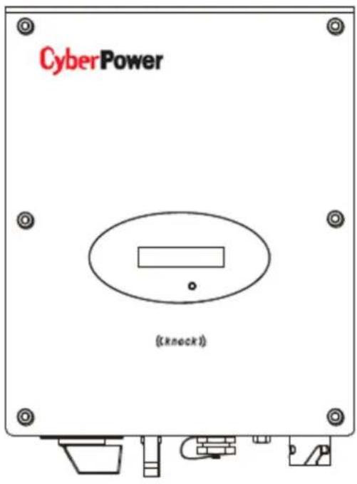
CyberPower ( (knock ) ) A B C D E F G| Posion | Descripon | Posion | Descripon |
| A | LCD | E | RS232 Port |
| B | LED | F | Waterproof breathable valve |
| C | DC switch | G | AC Output |
| D | PV input terminals |
On-grid Solar Power Generang System Introducon
Symbol on the On-grid Solar Power Generaon System
| Symbol | Description | Explanation |
 | Tap symbol | Setting the display operation by tapping the LCD |
 | On-grid Solar Power Generang System status symbol | Indicates On-grid Solar Power Generang System operation status |
Type label
The type labels provide a unique idencaon of the On-grid Solar Power Generang System (The type of product, Device-specific characteristics, Cercates and approvals). The type labels are on the right-hand side of the enclosure.| CyberPower | |
| Model Name | CPSPV3000ETL-S |
| Max. DC voltage | 550V |
| DC voltage range | 70V-550V |
| Full load voltage range | 250V-500V |
| Max. input current | 13A |
| Max. output power | 3kW/3kVA |
| Nominal output power | 3kW/3kVA |
| Nominal output current | 13 a.c.A |
| Nominal output voltage | 220/230 V |
| Nominal AC Frequency | 50Hz/60Hz |
| Power Factor | 0.9leading-0.9lgging |
| Safety Level | Class I |
| OVC | III |
| Protection Degree | IP65 |
| Operation ambient temperature | -25°C - +60°C |
| Model Name | CPSPV3000ETL-S |
| Max DC voltage | 550 |
| Max input current | 13A |
| MPP voltage range | 250V-500V |
| AC Nominal voltage | 220,230,240V; 180Vac-280Vac |
| AC grid frequency;Range | 50,60Hz;±5Hz |
| Max. AC output power | 3kW/3kVA |
| Nominal output current | 13 |
| Max. output current | 14.3A |
| Protecon Degree | IP65 |
| Operaon temperature range | -25°C ~ +60°C |
Startup Procedure
Check the PV Array DC Voltage
1. Uncover the PV arrays and expose them to full sunlight. The sunlight must be intense enough to produce the required output voltage. 2. Measure the PV array open circuit DC voltage across the DC positive (+) and negative (-) terminals. This voltage must greater than 70 volts DC (to energize the electronics) and less than 550 volts DC (to prevent damage to the On-grid Solar Power Generang System).Check the AC Utility Voltage
1. Switch on the main and On-grid Solar Power Generang System breakers in the main electrical service panel. 2. Using an AC voltmeter, measure the AC open circuit utility voltage between L (L1) and N (L2). Ensure the voltage is at approximately the nominal value. The On-grid Solar Power Generang System operates with the voltage range around the nominal value. See "Electrical Specicaon", output secon for the utility voltage operang range for your On-grid Solar Power Generang System model.Start up the On-grid Solar Power Generang System
1. Switch the DC and AC disconnecon switches (breakers) to the ON posion. 2. Check the On-grid Solar Power Generang System LCD. The startup screens should appear for several seconds, and then the "Countdown xx:xx" special screen will appear until protecon mer countdown is completed.Disconnect Test
The disconnect test is designed to verify correct operaon of the On-grid Solar Power Generang System both on initial operaon and periodically through its life as required by the ulies. This test ensures that On-grid Solar Power Generang System dose not send electricity to the utility grid when local utility has shut o the grid for repairs, or when the utility wiring is damaged.To run the disconnect test
1. Switch o the AC circuit for the On-grid Solar Power Generang System This can be accomplished by switching the breaker on the main panel that feeds the On-grid Solar Power Generang System. The disconnecon for the home or business may be used as well. 2. Have someone watch the front panel of the On-grid Solar Power Generating System to ensure the green light on the front of the On-grid Solar Power Generang System goes out. The green light goes out when AC circuit is switched o, disconnecting the On-grid Solar Power Generang System from the AC grid. The front panel display will show an AC voltage and frequency fault display, indicating that the AC is out of the operang range. 3 Switch on the AC circuit for the On-grid Solar Power Generang System The On-grid Solar Power Generang System responds by starng it reconnectng protecon mer. Ensure that the On-grid Solar Power Generang System does not produce power before the countdown is over. Aer compleng the countdown, the green light turns on and the On-grid Solar Power Generang System begins to send power to the grid. The display returns to show the power being produced and total kWh produced to date.IMPORTANT:
The default voltage, frequency and reconnect delay values are programmed into the unit at me of shipment from the factory. No changes to these settings can be made in the eld by the user. Only authorized personnel with utility permission may change these sengs.Commissioning
LCD display
In the lower center of On-grid Solar Power Generang System there is the LCD display. We can check On-grid Solar Power Generang System running status, etc. on the LCD screen. Items displayed can be changed by knock; you can also change some On-grid Solar Power Generang System parameters by knock. Starng-up display sequence, once the PV power is sucient, inverter displays informaon as shown in the ow chart as follow: SerNo: xxxxxxxxxxxx Module: xxxxxx XXXXXXXXXXXXXX FW Version: x.x.x Connect in: xxS Connect: OK Power: xxxx.xW Single Knock on the enclosure and the text line shown informaon about the CPS2000ETL-S:| CYCLE DISPLAY | REMARK |
| Energy generated today. | |
| Total generated energy since installation. | |
| Total operated times since installation | |
| PV:310V B:370V | PV voltage (PV) and Bus voltage (B) |
| AC:230V F:50.0Hz | Grid voltage (AC) and frequency (F) |
| SerNO:DK00000000 | Serial number |
| model: P1U1HQS3 | Model number |
| 0000000 00000000 | Product number |
| FW Version: H.1.0 | Firmware version of the inverter |
| COH Address: Move | Communication address of the inverter |
| Setting... | Parameters setting |
1. Language seng
Before entering the 'Set Language' interface, you need to enter a password as below: Setting... INPUT 123:XXX According to the LCD display, you need to input three numbers: 123. You should nish several steps as below: i. When the LCD stays bright, single knock to 'Seng...', and then double knock to enter 'INPUT 123:xxx'interface. ii. Double knock to make the rst number ash, single knock to change the number, and the rst number you need to input is '1'. Double knock to enter the second number while the rst number was '1'.Commissioning
iii. When the second number is ashing ,single knock to change the number,and the second number you need to input is '2'. Double knock to enter the last number while the rst number was '2'. iv. When LCD displays 'INPUT 123:123', triple knock to enter the seng interface.Set Language
v. Single knock to "set language" Double knock enter "language: English" Single knock to select the language. Aer seng, you need to wait a few seconds until the display becomes dark, then the seng will be saved. 2. Set luminance of LCD display i. If you want to set luminance of LCD display, repeat the steps as described in secon 6.1.1. ii. When LCD displays 'INPUT 123:123', triple knock to enter the seng interface.Set LCD contrast
iii. Single knock to "set LCD contrast" Double knock to enter "LCD contrast 2" Single knock to select the luminance. You also need to wait a few seconds aer selecng. When the display becomes dark, the change is saved. 3. Set communicaon address i. If you want to set communicaon address, repeat the steps as described in secon 6.1.1. ii. When LCD displays 'INPUT 123:123', triple knock to enter the seng interface.COM Address:xx
iii. Single knock to "COM Address: xx" → Double knock change the address to set model → Single knock to set address. Aer selecng, you need to wait a few seconds unl the display becomes dark, then the change is saved.LCD control
To save power, the LCD display's background light will turn off automatically in 20 seconds. Single knock will turn on the background light. The display on the On-grid Solar Power Generang System can be controlled by knocking the sound control panel in front of it.GFCI funcon
GFCI is short for Ground-Fault Circuit Interrupter which is used for preventing from being electric shock. The On-grid Solar Power Generang System is equipped with integrated RCD (Residual Current Protective Device) and RCM (Residual Current Operated Monitor). The current sensor will detect the volume of the leakage current and compare it with the pre-set value. If the leakage current is above the permied range, the RCD will disconnect the On-grid Solar Power Generang System from the AC load.PV isolaon detecon
The ISO funcon a protecon mechanism. The On-grid Solar PowerCommissioning
Generang System measures the resistances between both the positive pole and negative pole of PV panel and earth. Either of the measured value is lower than the limit, the PV On-grid Solar Power Generang System will not connect to grid, the output relay will stay open, and show 'PV isolaon low'. The limited value is determined by the standards. The rmware seng of our PV On-grid Solar Power Generang System is 500Kohm. The simplified principle of the isolaon resistance measurement is described as below: natural_image
Pure electrical circuit lines without any symbolsCommunicaon
1. Using 'Solar Power Setup\_3P' to Update rmware & monitor On-grid Solar Power Generang System About the soware -Solar Power Setup\_3P, please download from CyberPower ocial website. For more detail informaon about rmware upgrade, please refer to service manual or contact with CyberPower System, Inc. The connecng diagram as follow: flowchart
graph TD
    A["CyberPower"] --> B["RS232 cable"]
    A --> C["USB-RS232 cable"]
    B --> D["Computer"]
    C --> D
Startup and Shutdown the On-grid Solar Power Generang System
1. Start-Up the On-grid Solar Power Generang System i. If the On-grid Solar Power Generang System connects with PV panel arrays and the input voltage is higher than 70Vdc, while the AC grid is not connected yet, LCD will display messages in order as below: 'Ser NO: xxx'->'xxxxx'->'FW version'->'Waing'->'No AC conncon', the display repeats 'NO Ulity' and LED will be red. ii. Turn on the AC breaker or close the fuse between On-grid Solar Power Generang System and grid, the system will operate normally. iii. Under normal operang condions, the LCD displays 'Power: xxx.x W' at State info, this is the power fed into grid. LED turns green. 2. Shut down the On-grid Solar Power Generang System i. Turn o the AC grid breaker; ii. Turn o the DC switch of the On-grid Solar Power Generang System. iii. Check the On-grid Solar Power Generang System operang state. iv. Unl the display of LCD goes out, the On-grid Solar Power Generang System is shut down. Warning table| W00 | Solar input voltage low |
| W04 | Solar input voltage high |
| E00 | No Grid |
| E01 | AC frequency high (According to code setting table) |
| E02 | AC frequency low (According to code setting table) |
| E03 | AC voltage high (According to code setting table) |
| E04 | AC voltage low (According to code setting table) |
Fault table
(Usually you need to call service people if there is always fault condition happened)| F01 | Hardware DC injection of output current (According to code setting table) |
| F05 | Temperature sensor 1 low |
| F06 | Temperature sensor 1 high |
| F07 | Hardware temperature sensor 1 failure |
| F08 | Temperature sensor 2 high |
| F09 | Hardware temperature sensor 2 failure |
| F10 | Temperature sensor 3 high |
| F11 | Hardware temperature sensor 3 |
| failure | |
| F15 | Hardware main DSP ADC1 failure |
| F16 | Hardware main DSP ADC2 failure |
| F17 | Hardware main DSP ADC3 failure |
| F18 | Hardware main DSP ADC4 failure |
| F19 | Hardware redundant MCU ADC1 failure |
| F20 | Hardware efficiency failure |
| F22 | Hardware communication 1 failure |
| F23 | Hardware communication 2 failure |
| F24 | Residual current failure (According to code setting table) |
| F25 | Hardware RCMU failure |
| F26 | Input insulation failure |
| F28 | Hardware relay short |
| F29 | Hardware relay open |
| F31 | Hardware DC Bus 1 OVP |
| F33 | Hardware DC Bus 2 OVP |
| F36 | AC output current high (fast) |
| F37 | AC output current high (slow) |
| F42 | Hardware CT failure |
| F45 | Hardware AC current OCP |
| F60 | DC input current high (slow) |
| F70 | DC input current high (fast) |
TECHNICAL SPECIFICATIONS
| ModelSpecicaons | CPSPV3000ETL-S |
| Input data (DC) | |
| Max. DC power | 3400W |
| Max. DC voltage | 550V |
| Start voltage | 80V |
| PV voltage range | 70V-550V |
| MPP work voltage range/ nominal voltage | 70V-550V/250V |
| Full load dc voltage range | 250V-500V |
| Max. input current | 13A |
| Max. input current per string | 13A |
| Number of independent MPP trackers /strings per MPP tracker | 1/1 |
| Output (AC) | |
| Rated AC output power | 3000W |
| Max. AC power | 3000W |
| Max. output current | 14.3A |
| AC nominal voltage; range | 220,230,240V; 180Vac-280Vac |
| AC grid frequency; range | 50,60Hz;±5Hz |
| Power factor | >0.99 |
| THDI | <3% |
| AC conncon | Single phase |
| Eciency | |
| Max. eciency | 97.4% |
| Euro weighted eciency | 97% |
| MPPT eciency | 99.5% |
| Protecon devices | |
| DC reverse polarity protecon | Yes |
| DC switch rang for each MPPT | Yes |
| Output over current protecon | Yes |
| Output over voltage protecon-varistor | Yes |
| Ground fault monitoring | Yes |
| Grid monitoring | Yes |
| Integrated all - pole sensitive leakage current monitoring unit | Yes |
TECHNICAL SPECIFICATIONS
| General Data | |
| Dimensions (W / H / D) in mm | 320*267*142 |
| Weight | 6.6KG |
| Operating temperature range | -25°C ... +60°C (-13...+140°F) with derating above 50°C /122°F |
| Noise emission (typical) | ≤ 25 dB(A) |
| Altitude | 2000m(6560ft) without derating |
| Self-Consumption night | < 0.5 W |
| Topology | Transformerless |
| Cooling concept | Natural |
| Environmental Protection Rating | IP65 |
| Relative humidity | 100% |
| Features | |
| DC connection | H4 |
| AC connection | Connector |
| Display | LCD |
| Interfaces: RS232//Wifi | yes/opt |
| Warranty: 5 years / 10 years | yes /opt |
| Certificates and approvals | CE, VDE 0126-1-1, IEC 62109, G83, EN50438, |