CPSPV40000ETL - Solar panel CyberPower - Free user manual and instructions
Find the device manual for free CPSPV40000ETL CyberPower in PDF.

User questions about CPSPV40000ETL CyberPower
0 question about this device. Answer the ones you know or ask your own.
Ask a new question about this device
Download the instructions for your Solar panel in PDF format for free! Find your manual CPSPV40000ETL - CyberPower and take your electronic device back in hand. On this page are published all the documents necessary for the use of your device. CPSPV40000ETL by CyberPower.
USER MANUAL CPSPV40000ETL CyberPower
Reliability. Quality. Value.
CPSPV30000ETL
CPSPV33000ETL
CPSPV40000ETL
User's Manual
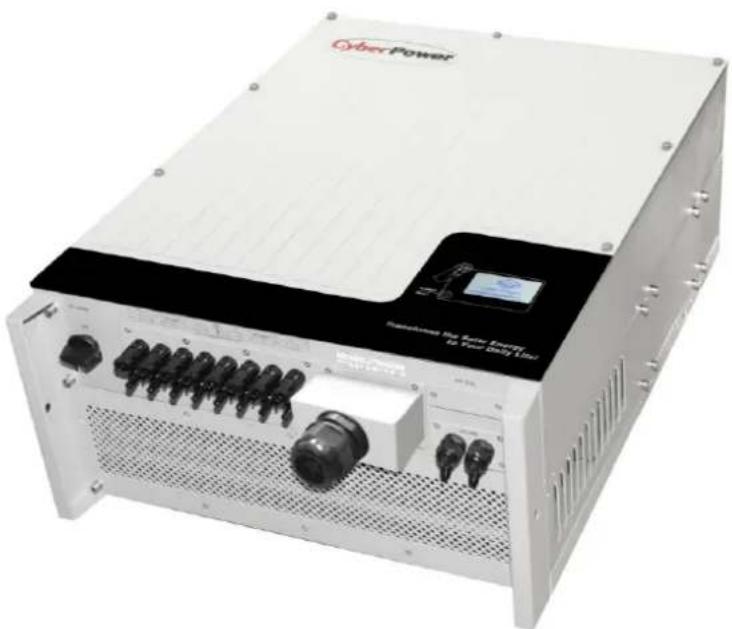
natural_image
Exterior view of a white industrial power supply unit with visible ports and connectors (no readable text or symbols)CyberPower Systems Inc.
www.cpsww.com
Index
1 Informaon on this Manual .... 3
1.1 Validity .... 3
1.2 Target Group 3
1.3 Symbols Used.... 3
2 Safety 4
2.1 Intended Use....4
2.2 Safety Precauons 5
2.3 Assembly Warnings....5
2.4 Electrical Connection Warnings 6
2.5 Operaon Warnings....7
2.6 Symbols on the On-grid Solar Power Generang System....8
3 Product Descripon....9
3.1 CPS Mini Central series overview....9
3.2 Type label....10
3.3 Size and weight 11
3.4 Transportaon....12
3.5 Storage of On-grid Solar Power Generang System 12
3.6 The advantage of the CPS Mini Central On-grid Solar Power Generang System.... 12
4 Unpacking 13
5 Installaon 14
5.1 Safety instrucon....14
5.2 Selecting the Installaon Locaon 15
5.3 Installaon guide 16
5.3.1 Mounng the Bracket 16
5.3.2 Mounng On-grid Solar Power Generang System....18
5.3.3 Installaon layout 19
5.4 Electrical Connecons.... 21
5.4.1 Safety 21
5.4.2 Wiring AC Output....21
5.4.3 Wiring DC Input 24
5.4.4 Grounding 26
5.5 Grid Type 27
5.5.1 Common grid type 27
5.5.2 Compatibility Table 28
6 Commissioning....29
6.1 Commission the On-grid Solar Power Generating System 29
6.2 Operaon Modes.... 29
6.3 Inial Sengs and LCD Display 30
6.3.1 Inial Sengs 30
6.3.2 Power on Display 32
6.3.2.3 Connecting messages.... 34
6.3.2.4 LCD Lock and unlock 34
6.3.3 Operate by knock 34
6.3.4 Data checking and parameters seng 35
6.4 Double MPPT of the CPS Mini Central 42
6.5 Communication....43
6.5.1 Using 'Solar Power Setup_3P' to Update rmware & monitor On-grid Solar Power Generang System....43
6.5.2 Monitor the On-grid Solar Power Generang System 43
6.5.3 RS485 cable conneccon 44
7 Start-Up and shut down the On-grid Solar Power Generang System 47
7.1 Start-Up the On-grid Solar Power Generating System 47
7.2 Shut down the On-grid Solar Power Generating System 47
8 Maintenance and Cleaning 48
8.1 Cleaning Fans and Grills 48
8.2 Exchange Fan 49
9 Trouble shoong....50
9.1 Error Messages displayed on LCD 50
9.1.1 System fault 51
9.1.2 On-grid Solar Power Generating System warning....51
9.1.3 On-grid Solar Power Generating System fault 52
10 Decommissioning 53
10.1 Dismantling the On-grid Solar Power Generang System 53
10.2 Packing the On-grid Solar Power Generang System 53
10.3 Disposing of the On-grid Solar Power Generang System....53
11 Specicaon....54
11.1 Specicaon of CyberPower Mini Central Series....54
11.2 Torque Values....55
12 Cercates .... 55
13 Contact....56
1 Informaon on this Manual
1.1 Validity
This installaon guide contains installaon, commissioning, communicaon, trouble shoong. Informaon of CPS Mini Central series:
- CPSPV30000ETL
CPSPV33000ETL
CPSPV40000ETL
With this installaon guide, users are able to install and operate the On-grid Solar Power Generang System easily. This manual does not cover any details concerning equipment connected to the CPS Mini Central series. Store this manual where accessible at all mes.
1.2 Target Group
This manual is for qualified persons such as PV system installers or electricians.
Notes: For possible changes in this manual, CyberPower Systems, Inc. accepts no responsibilities to inform the users
1.3 Symbols Used
The following types of safety instrucons and general informaon appear in this document as described below:
| Symbol | descripon | |
 | Read the manual | |
 | DANGER | DANGER indicates a hazardous situaon which, if not avoided, will result in death or serious injury. |
 | WARNING | WARNING indicates a hazardous situaon which, if not avoided, could result in death or serious injury. |
 | CAUTION | CAUTION indicates a hazardous situaon which, if not avoided, could result in minor or moderate injury. |
 | NOTICE | NOTICE indicates a situaon which, if not avoided, could result in property damage. |
 | Information | Informaonthat you must read and know to ensure opmal operaon of the system. |
2 Safety
2.1 Intended Use
CPS Mini Central series On-grid Solar Power Generang System are to be used solely to feed solar energy converted photovoltaically into the public grid. CPS Mini Central series On-grid Solar Power Generang System are mul-string On-grid Solar Power Generang System with mul-MPP trackers, which mean they are able to connect to dierent PV module arrays. The equipment may only be operated in compliance with its intended use.
Grid-ed PV system Overview:

flowchart
graph LR
    A["PV Panel"] --> B["String Fuse"]
    C["PV Panel"] --> D["String Fuse"]
    B --> E["On-grid Solar Power Generating System"]
    D --> E
    E --> F["AC Breaker"]
    F --> G["Public Geid"]
Fig 1.1
The On-grid Solar Power Generang System may only be operated with a permanent conncon to the public power grid. The On-grid Solar Power Generang System is not intended for mobile use. Any other or additional use is not considered as intended use. The manufacturer is not
responsible for any damages resulting from unintended use. Damage caused by such unintended use is at the sole risk of the operator.
As drawings shown above, a complete Grid-ed PV system consists of PV modules, On-grid Solar Power Generang System, public grid and other components. Moreover, On-grid Solar Power Generang System always act as key components.
PV modules Capacitive Discharge Currents
PV modules with large capacities relave to earth, such as thin-lm PV modules with cells on a metallic substrate, may only be used if their coupling capacity does not exceed 470nF. During feed-in operaon, a leakage current ows from the cells to earth, the size of which depends on the manner in which the PV modules are installed (e.g. foil on metal roof) and on the weather (rain, snow). This "normal" leakage current may not exceed 50mA due to the fact that the On-grid Solar Power Generang System would otherwise automacally disconnect from the electricity grid as a protecve measure.
| i Information | If PV modules of the PV system require POSITIVE or NEGATIVE to connect to GROUND, or the capacitance relave to ground of the modules is large, please contact CyberPower Systems, Inc. for technical support before installaon. |
2.2 Safety Precauons
The CPS Mini Central series is designed and tested according to internaonal safety requirements; however, certain safety precautions must be observed when installing and operating this On-grid Solar Power Generang System. Read and follow all instrucons, cauons and warnings in this installaon manual.
2.3 Assembly Warnings
 WARNING WARNING | Prior to installaon, inspect the unit to ensure absence of any transport or handling damage, which could aect insulaon integrity or safety clearances; failure to do so could result in safety hazards.Unauthorized removal of necessary protecons, improper use, incorrect installaon and operaon may lead to serious safety, shock hazards or equipment damage.In order to minimize the potenal of a shock hazard due to hazardous voltages, cover the enre solar array with dark material prior to connecng the array to any equipment. |
 CAUTION CAUTION | Grounding the PV modules: Comply with the local requirements for grounding the PV modules and the PV generator.CyberPower recommends connecng the generator frame and other electrically conductive surfaces in a manner which ensures connuous conducon and ground these in order to have opmal protecon of the system and personnel. |
2.4 Electrical Connecon Warnings
 | DANGER | Some components in the On-grid Solar Power Generang System are live. Touching live components can result in serious injury or death.Danger to life due to high voltages in the On-grid Solar Power Generang SystemAll work on the On-grid Solar Power Generang System may be carried out by qualified personnel only.The appliance is not to be used by children or persons with reduced physical, sensory or mental capabilities, or lack of experience and knowledge, unless they have been given supervision or instrucon.Children are forbidden to play around the CPS Mini Central series. | |
 | WARNING | Make all electrical connecons (e.g. conductor termination, fuses, PE conncon, etc.) in accordance with prevailing regulaons. When working with the On-grid Solar Power Generang System powered on, adhere to all prevailing safety regulaons to minimize risk of accidents.The CPS Mini Central series may only be operated with PV generators (modules and cabling) with protecve insulaon. Do not connect any source of energy other than PV modules to the CPS Mini Central series.Systems with On-grid Solar Power Generating System typically require additional control (e.g., switches, disconnects) or protecve devices (e.g., fusing circuit breakers) depending upon the prevailing safety rules.Please read this manual carefully, the manufacturer or supplier is not responsible for damage caused by incorrect operaon, installaon, wiring, transport, etc. | |
 | CAUTION | The CPS Mini Central series is to be used solely to feed solar energy converted photovoltaic into the public grid. The On-grid Solar Power Generang System is suitable for mounng indoors and outdoors.You can use the AC current generated as follows: | |
| House grid: | Energy ows into the house grid. The consumers connected, for example, household devices or lighng, consume the energy. The energy le over is fed into the public grid. When the CPS Mini Central series do not generate any energy, e.g., at night, the consumers which are connected are supplied by the public grid. The energy displayed on the LCD of On-grid Solar Power Generang System is for reference only. When energy is fed into the public grid, the energy meter spins backwards. | ||
| Public grid: | Energy is fed directly into the public grid. The CPS Mini Central series need install a separate energy meter. The energy produced is compensated at a rate depending on the electric power company. | ||
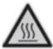
2.5 Operaon Warnings
 WARNING WARNING | ➢ Ensure all covers and doors are closed and secure during operaon.➢ Although designed to meet all safety requirements, some parts and surfaces of On-grid Solar Power Generang System are sll hot during operaon. To reduce the risk of injury, do not touch the heat sink at the back of the PV-On-grid Solar Power Generang System or nearby surfaces while On-grid Solar Power Generang System is operang.➢ Incorrect sizing of the PV plant may result in voltages being present which could destroy the On-grid Solar Power Generang System. The On-grid Solar Power Generang System display will read the error message “PV Voltage High ”● Turn the rotary switch of the DC Disconnect to the O posion immediately.● Contact installer. |
 CAUTION CAUTION | ➢ All operations regarding transport, installaon and start-up, including maintenance must be operated by qualified, trained personnel and in compliance with all prevailing codes and regulaons.➢ Anyme the On-grid Solar Power Generang System has been disconnected from the power network, use extreme cauon as some components can retain charge sufficient to create a shock hazard; to minimize occurrence of such condions, comply with all corresponding safety symbols and markings present on the unit and in this manual.➢ In special cases, there may sll be interference for the specied applicaon area despite maintaining standardized emission limit values (e.g. when sensitive equipment is located at the setup locaon or when the setup location is near radio or television receivers).In this case, the operator is obliged to take proper acon to recfy the situaon.➢ Possible damage to health as a result of the eects of radiaon!● Do not stay closer than 20 cm to the On-grid Solar Power Generang System for any length of me. |
2.6 Symbols on the On-grid Solar Power Generang System
| Symbol | Explanaon |
 | Refer to operaon instrucon |
 | Cauon, risk of electrical shock |
 | Cauon, hot surface |
 | Earth (ground) terminal |
 | Cauon, risk of electrical shock.Energy stored discharge me. |
 | Direct Current (DC) |
 | Alternang Current (AC) |
 | CE mark.The On-grid Solar Power Generang System complies with the requirements of the applicable EC guidelines. |
3 Product Descripon
3.1 CPS Mini Central series overview
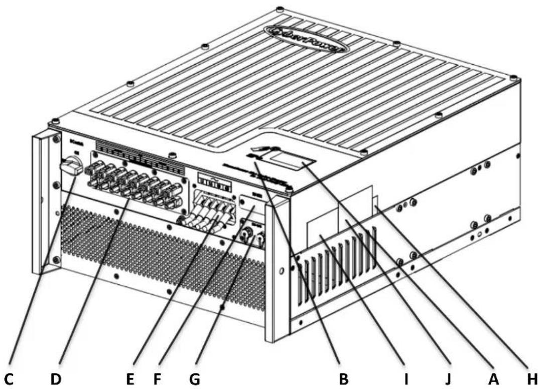
text_image
C D E F G B I J A H| Posion | Descripon |
| A | LCD |
| B | LED |
| C | DC Switch |
| D | PV input terminals |
| E | AC output |
| F | RS232 lid |
| G | RS485 |
| H | Serial Number |
| I | Warning Label |
| J | Type label |
Symbol on the On-grid Solar Power Generating System

text_image
Normal Fault| Symbol | Descripon | Explanaon | |
 | Tap symbol | Indicates display operaon (see Secon 6). | |
 | On-grid Solar Power Generang System state symbol | Green/constant | Operaon |
| Red/constant | 1、Fault-- contact installer2、Standby module | ||
| Red/ashing | 1、Fans Fault-- contact installer2、Soware update | ||
3.2 Type label
The type labels provide a unique idencaon of the On-grid Solar Power Generang System (The type of product, Device-specific characteriscs, Cercates and approvals). The type labels are on the right-hand side of the enclosure.
| CyberPowerOn-grid Solar Power Generating System | |
| Model Name | CPSPV30000ETL |
| Max. DC voltage | 1000V |
| DC voltage range | 300V-1000V |
| Full load voltage range | 460V -800V |
| Max. input current | 35A*2 |
| Max. output power | 30kW/30kVA |
| Nominal output current | 45.5A |
| Nominal output voltage | 230V/400V(3/N/PE) |
| Nominal AC Frequency | 50Hz /60Hz |
| Power Factor | 0.9leading-0.9laging |
| Safety Level | Class I |
| OVC | III |
| Protection Degree | IP65 |
| Operation Ambient Temperature | -25°C - +60°C |
| CE VDE 0126-1-1CE, IEC 62109 | |
| CyberPowerOn-grid Solar Power Generating System | |
| Model Name | CPSPV33000ETL |
| Max. DC voltage | 1000V |
| DC voltage range | 300V-1000V |
| Full load voltage range | 460V -800V |
| Max. input current | 38A*2 |
| Max. output power | 33kW/33kVA |
| Nominal output current | 50A |
| Nominal output voltage | 230V/400V(3/N/PE) |
| Nominal AC Frequency | 50Hz /60Hz |
| Power Factor | 0.9leading-0.9laging |
| Safety Level | Class I |
| OVC | III |
| Protection Degree | IP65 |
| Operation Ambient Temperature | -25°C - +60°C |
| CE VDE 0126-1-1CE, IEC 62109 | |
| CyberPowerOn-grid Solar Power Generating System | |
| Model Name | CPSPV40000ETL |
| Max. DC voltage | 1000V |
| DC voltage range | 300V-1000V |
| Full load voltage range | 550V - 800V |
| Max. input current | 38A*2 |
| Max. output power | 40kW/40kVA |
| Nominal output current | 50A |
| Nominal output voltage | 277V/480V (3/PE) |
| Nominal AC Frequency | 50Hz /60Hz |
| Power Factor | 0.9leading-0.9laging |
| Safety Level | Class I |
| OVC | III |
| Protection Degree | IP65 |
| Operation Ambient Temperature | -25°C - +60°C |
| CE VDE 0126-1-1CE, IEC 62109 | |
More detail about the type label as the chart below:
| Model Name | CPSPV30000ETL | CPSPV33000ETL | CPSPV40000ETL |
| Max DC voltage | 1000V | 1000V | 1000V |
| Max input current | 35A / 35A | 38A / 38A | 38A / 38A |
| MPP voltage range | 460V-1000V | 460V-1000V | 550V-1000V |
| AC Nominal voltage | 3/N/ PE230V/400V | 3/N/ PE230V/400V | 3/ PE277V/480V |
| AC grid frequency; Range | 50/60Hz-6Hz/+5Hz | 50/60Hz-6Hz/+5Hz | 50/60Hz-6Hz/+5Hz |
| Max. AC output power | 30kW/30kVA | 33kW/33kVA | 40kW/40kVA |
| Nominal output current | 43.5A | 47.8A | 48.1A |
| Max. output current | 45.5A | 50A | 50A |
| Protecon Degree | IP65 | IP65 | IP65 |
| Operaon temperature range | -25°C ~ +60°C | -25°C ~ +60°C | -25°C ~ +60°C |
3.3 Size and weight
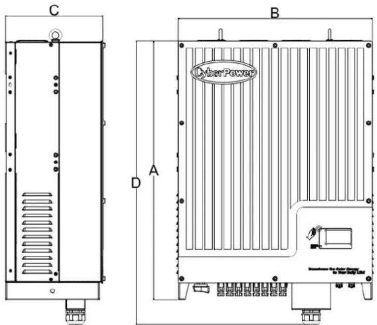
text_image
C D A B CyberPower| A(mm) | B(mm) | C(mm) | D(mm) | Weight(kg) | |
| CPSPV30000ETL | 740 | 550 | 276 | 778 | 61.6 |
| CPSPV33000ETL | |||||
| CPSPV40000ETL |
3.4 Transportation
The On-grid Solar Power Generating System is thoroughly tested and inspected strictly before delivery. Our On-grid Solar Power Generating System leave our factory in proper electrical and mechanical condition. Special packaging ensures safe and careful transportation. However, transport damage may still occur. The shipping company is responsible in such cases. Thoroughly inspect the On-grid Solar Power Generating System upon delivery. Immediately notify the responsible shipping company if you discover any damage to the packaging which indicates that the On-grid Solar Power Generating System may have been damaged or if you discover any visible damage to the On-grid Solar Power Generating System. We will be glad to assist you, if required. When transporting the On-grid Solar Power Generating System, the original or equivalent packaging should be used, and the maximum layers for original carton is four, as this ensures safe transport.
3.5 Storage of On-grid Solar Power Generating System
If you want to storage the On-grid Solar Power Generating System in your warehouse, you should choose an appropriate location to store the On-grid Solar Power Generating System.
The unit must be stored in original package and desiccant must be left in the package.
The storage temperature should be always between -25°C and +70°C. And the storage relative humidity should be always between 0 and 95%.
If there are lots of On-grid Solar Power Generating System need to be stored, the maximum layers for original carton is four.
➢ After long term storage, local installer or service department of CyberPower should perform a comprehensive test before installation
4 Unpacking
Before opening the packing box of CPS Mini Central On-grid Solar Power Generang System, please note that whether there are any visible external damages.
Once open the packing box, please check the delivery for completeness and for any visible external damages of the On-grid Solar Power Generang System. If there are anything damaged or missing, please contact your dealer. Complete delivery should contain as follows.
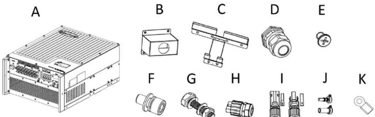
text_image
A B C D E F G H I J KFig 4.1
| Item | quantity | Descripon |
| A | 1 pcs | CPS Mini Central On-grid Solar Power Generang System |
| B | 1 pcs | Waterproof cover for AC power cable |
| C | 1 pcs | Wall-Mount bracket |
| D | 1 set | Cable gland for AC connection |
| E | 4 pcs | M4 cross recessed countersunk head screws for Waterproof cover |
| F | 2 set | M6 socket head cap screws for fix On-grid Solar Power Generating System on wall mount bracket |
| G | 6 set | Hex head cap screw and nuts for wall mount bracket |
| H | 2 set | RS485 waterproof plug assembly |
| I | 4 set | Field Wiring DC connectors |
| J | 6 set | Plugs for unused PV terminals |
| K | 5 pcs | Ring Terminals |
| -- | 1 pcs | Warranty(not show in the picture) |
| -- | 1 pcs | User manual (not show in the picture) |

Information
Though the packaging box of CPS Mini Central On-grid Solar Power Generang System is durable, please treat the packing box gently and avoid dispose the packing box.
5 Installaon
5.1 Safety instrucon
 | Danger to life due to re or explosion➢ Despite careful construcon, electrical devices can cause res.➢ Do not install the On-grid Solar Power Generang System on easily ammable materials and where ammable materials are stored. |
 | Risk of burns due to hot enclosure partsMount the On-grid Solar Power Generang System in such a way that it cannot be touched inadvertently. |
All electrical installaons shall be done in accordance with the local and naonal electrical codes. Do not remove the casing. On-grid Solar Power Generang System contains no user serviceable parts. Refer servicing to qualified service personnel. All wiring and electrical installaon should be conducted by a qualified service personnel.
Carefully remove the unit from its packaging and inspect for external damage. If you nd any imperfecons, please contact your local dealer.
Be sure that the On-grid Solar Power Generang System connect to the ground in order to protect property and personal safety.
The On-grid Solar Power Generang System must only be operated with PV generator. Do not connect any other source of energy to it.
Both AC and DC voltage sources are terminated inside the On-grid Solar Power Generang System. Please disconnect these circuits before servicing.
This unit is designed to feed power to the public power grid (ulity) only. Do not connect this unit to an AC source or generator. Connecng On-grid Solar Power Generang System to external devices could result in serious damage to your equipment.
When a photovoltaic panel is exposed to light, it generates a DC voltage. When connected to this equipment, a photovoltaic panel will charge the DC link capacitors.
Energy stored in this equipment's DC link capacitors presents a risk of electric shock. Even aer the unit is disconnected from the grid and photovoltaic panels, high voltages may sll exist inside the PV-On-grid Solar Power Generang System. Do not remove the casing unl at least 5 minutes aer disconnecting all power sources.
Although designed to meet all safety requirements, some parts and surfaces of On-grid Solar Power Generang System are sill hot during operaon. To reduce the risk of injury, do not touch the heat sink at the back of the PV-On-grid Solar Power Generang System or nearby surfaces while On-grid Solar Power Generang System is operang.
5.2 Selecng the Installaon Locaon
This is guidance for installer to choose a suitable installaon locaon, to avoid potenal damages to device and operators.
1) The wall selected to install the On-grid Solar Power Generang System must be strong and rm enough to support and bear the weight of the On-grid Solar Power Generang System for a long period me. (Refer to Chapter 11 Specicaons)
2) The location selected must be suitable for On-grid Solar Power Generang System' dimension. (Refer to 3.3 Dimensions and Fig.5.2 Required Clearances)
3) Do not install the On-grid Solar Power Generang System on structures constructed of ammable or thermo-labile materials.
4) Never install the On-grid Solar Power Generang System in environment of lile or no air ow, nor dust environment.
5) The Ingress Protecon rate is IP65 which means the On-grid Solar Power Generang System can be installed outdoors and indoors.
6) Do not expose the On-grid Solar Power Generang System to direct sunlight, in order to avoid the power and eciency derang caused by excessive heang.
7) The humidity of the installation locaon should be 0\~95% without condensaon.
8) The ambient temperature of the On-grid Solar Power Generating System should be -25°C\~+60°C.
9) The installation locaon must be freely and safely to get at all mes.
10) Vercally installaon and make sure the conneccon of On-grid Solar Power Generating System must be downwards. Never install horizontal and avoids forward and sideways lt.( Refer to drawings below)

text_image
90° 15°Fig 5.1
11) Noce the minimum clearances of the On-grid Solar Power Generang System. (Refer to 3.3 Dimensions and Fig.5.2 Required Clearances).

text_image
50 CM 30 CM 30 CM 50 CMFig 5.2
12) Do not install the On-grid Solar Power Generang System near television antenna or any other antennas and antenna cables.
13) Do not install the On-grid Solar Power Generang System in living area, the noise caused by the machine may act daily life.
14) For security reasons, don't install the On-grid Solar Power Generang System in place where the children can reach.
5.3 Installaon guide
5.3.1 Mounng the Bracket

DANGER
In order to avoid electrical shock or other injury, inspect existing electronic or plumbing installations before drilling holes.
To mount the On-grid Solar Power Generang System on the wall, we should mount the bracket to the wall rmly rst of all.

text_image
S30.0 420.0 140.0 Fix the bracket with screw and nuts 220.0 80.0 Fix the On-grid Solar Power Generating System with M6 screw 320.0Dimension of Bracket (units :mm)
Fig 5.3
Steps:
● Drill 6 holes for screws while use the moung frame as template.
● Fix the moung frame on the wall as the gures shown below, combine as the screws as the Items Fig 4.1 shows (items D)

natural_image
Technical line drawing of a mechanical assembly mounted on a brick wall, with an inset magnified detail showing a separate view (no text or symbols present)Fig 5.4
5.3.2 Mounng On-grid Solar Power Generang System

WARNING
Falling equipment can cause serious or even fatal injury, never mount the On-grid Solar Power Generang System on the bracket unless you are sure that the mounng frame is really rmly mounted on the wall aer carefully checking.
Aer the bracket is rmly mounted on the wall, then mount the On-grid Solar Power Generang System on the bracket.
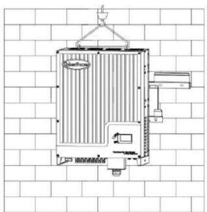
- Rise up the CPS Mini Central a lile higher than the bracket. Considering the weight of CPS Mini Central, you need to hang on the On-grid Solar Power Generang System. During the process please maintain the balance of the CPS Mini Central.
- Hang the On-grid Solar Power Generang System on the bracket through the match hooks on bracket and the back of the On-grid Solar Power Generang System. Please reference in Fig5.5
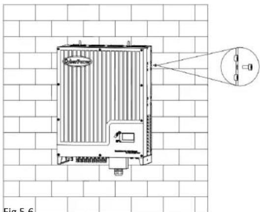
- Installed one M6*10 screw at each side of On-grid Solar Power Generang System to reliable xed it on the wall. Please reference in Fig 5.6.
● Connecon of a second protective earthing conductor. Please reference in Fig5.7. - Recommend awning installaon, the purpose is to extend the On-grid Solar Power Generating System service life and reduce the power derang of the On-grid Solar Power Generang System. The dimension of the awning refer to Fig5.8.
natural_image
Technical line drawing of a portable air conditioner unit mounted on a brick wall (no text or symbols)Fig 5.5 Fig 5.6
natural_image
Technical line drawing of a heat exchanger unit mounted on a brick wall, with no visible text or symbols.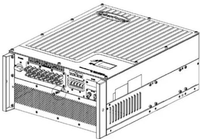
natural_image
Technical line drawing of a server rack unit with ventilation grilles and ports (no text or labels)Fig. 5.7
5.3.3 Installaon layout

Information
Avoid exposing On-grid Solar Power Generang System to direct sunlight, rain or snow to extend the On-grid Solar Power Generang System service life despite the IP65 protecon degree. Exposure to the sunlight may cause

text_image
Illustration showing six different household scenarios with sun, rain, and fireworks symbols, each marked with a checkmark and an 'X' symbol.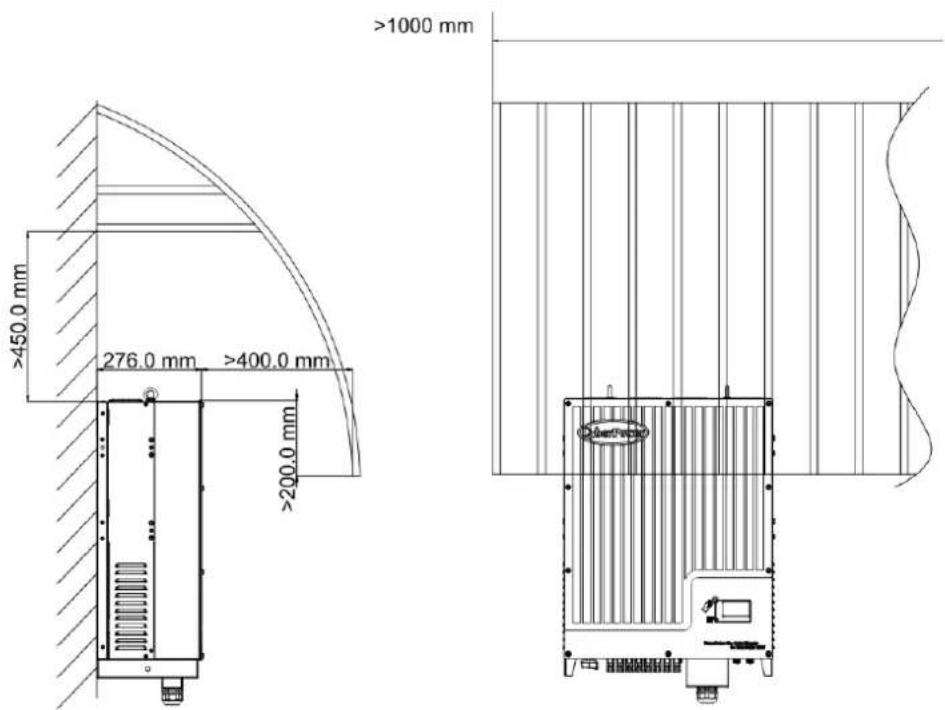
text_image
≥1000 mm ≥450.0 mm 276.0 mm ≥400.0 mm ≥200.0 mmFig. 5.8
More than one On-grid Solar Power Generang System need to be installed, the dimensions below should be considered.
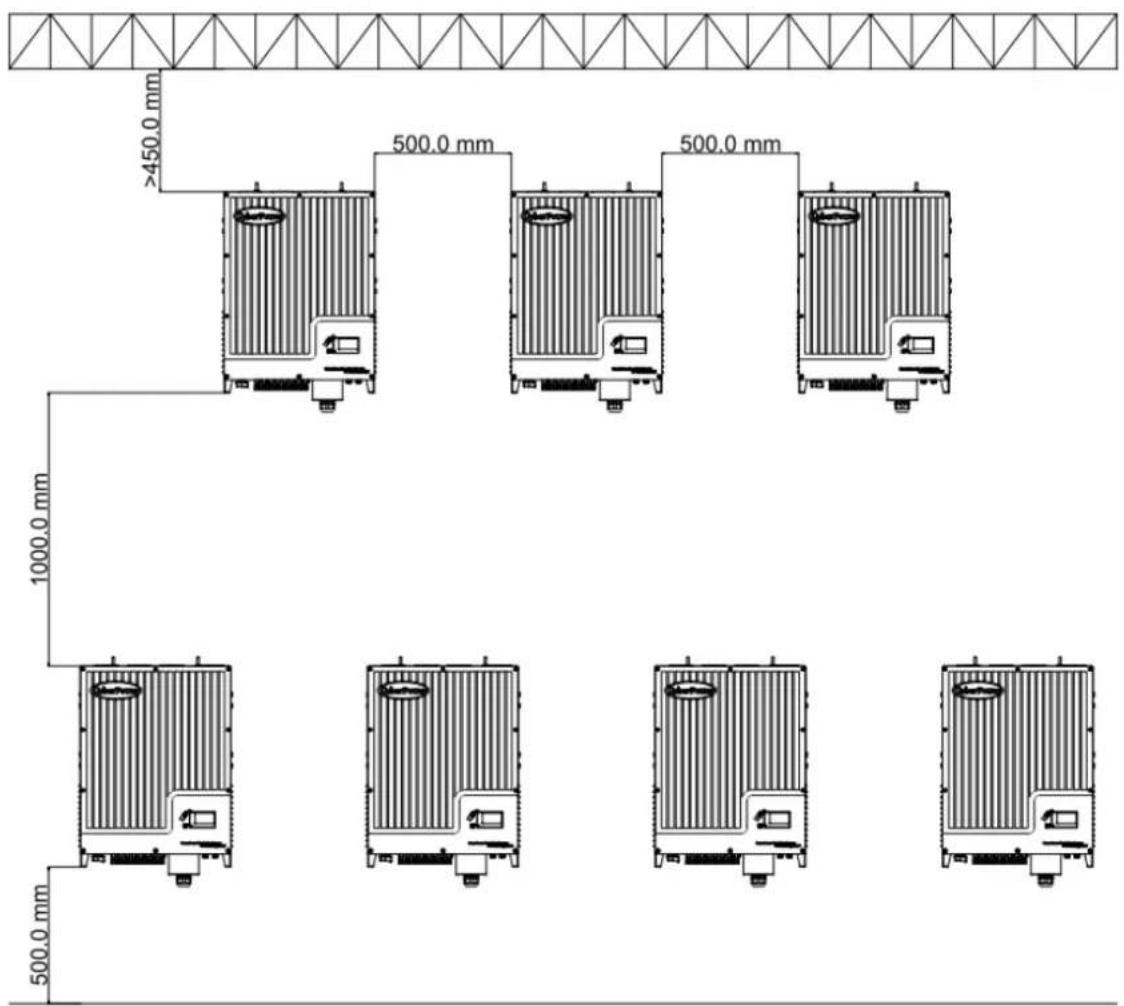
text_image
>450.0 mm 500.0 mm 500.0 mm 1000.0 mm 500.0 mmFig. 5.9
5.4 Electrical Connecons
5.4.1 Safety
 | DANGER | Danger to life due to hazards voltages!High voltages which may cause electric shocks are present in the conducive parts of the On-grid Solar Power Generang System. Prior to performing any work on the On-grid Solar Power Generang System, disconnect the On-grid Solar Power Generang System on the AC and DC sides |
 | WARNING | Danger of damage to electronic components due to electrostac discharge.Take appropriate ESD precautions when replacing and installing the On-grid Solar Power Generang System. |
5.4.2 Wiring AC Output
Condions for the AC Connecon
You must comply with the conneccon requirements of your ulity operator.
All usages must comply with the regulaons.
Residual-current protecve device
The On-grid Solar Power Generang System is equipped with an integrated universal residual-current monitoring unit.
If the network operator spulates a residual-current protecve device, you must use a
residual-current protecve device that triggers in the event of a residual-current of 100 mA or more.
Connecon of a second protective conductor
In some installaon countries, a second protecve conductor is required to prevent a touch current in the event of a malfuncon in the original protecve earthing conductor.
For installaon countries falling within the scope of validity of the IEC standard 62109, you must install the protective conductor on the AC terminal with a conductor cross-second of at least 10mm^2Cu .
Or install a second protecve conductor on the earth terminal with the same cross-secon as the original protecve earthing conductor on the AC terminal
Load disconnecon unit
You must install a separate three-phase miniature circuit-breaker or other load disconnexcon unit for each On-grid Solar Power Generang System in order to ensure that the On-grid Solar Power Generang System can be safely disconnected under load.
● Measure the public grid voltage and frequency
Note,
Nominal 3-Phase line to line voltage is 400Vac for model CPSPV30000ETL/CPSPV33000ETL and 480Vac for model CPSPV40000ETL
- Open the DC Switch between the On-grid Solar Power Generang System and utility;
Specicaon of AC breaker: CPSPV30000ETL: 63A/400V
CPSPV33000ETL: 80A/400V
CPSPV40000ETL: 80A/480V
AC Power Cable requirements:
| Model | Cable outer Diameter (mm) | Cross-secon Conductor Area (mm2) | Available wire gauge (AWG) |
| CPSPV30000ETL | 3.67~4.62 | 10~16 | 7~5 |
| CPSPV33000ETL | 3.67~4.62 | 10~16 | 7~5 |
| CPSPV40000ETL | 3.67~4.62 | 10~16 | 7~5 |
| ConductorCross secon | Max. cable length(m) | ||
| CPSPV30000ETL | CPSPV33000ETL | CPSPV40000ETL | |
| 10.0 mm2 | 30 | 25 | 25 |
| 14.0 mm2 | 42 | 38 | 38 |
| 16.0 mm ^2 | 50 | 45 | 45 |

NOTICE
Please do not use single-core wire cable.
There are two types of AC connector for CPS Mini Central series On-grid Solar Power Generang System. Please follow the instrucons corresponding to the parts we oer.
AC terminal :
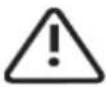
1) The AC side terminals of the On-grid Solar Power Generang System are like the following gure, it is clear to conrm that 'L1, L2, L3' represents three live line output, 'N' represents ne al line and is grounding line. Note that, CSPV40000ETL have no 'N' terminal. See Fig 5.10.
Following diagram illustrate the step of installaon for AC conncon with CSPV30000ETL and CSPV33000ETL. The similar step can be applied CSPV40000ETL, except the cable no is 4 instead of 5 because there is no 'N' required.
2) Connect standard cables into relevant terminals.
The cables should be put through the protecon shell, then to press the ring terminal onto the AC cable. Following with ghten the ring terminal to AC terminal block shown as gure below. See Fig 5.11
3) Fasten the protecon shell onto the boom of the On-grid Solar Power Generang System, make sure the four screws are ghtened, the completed appearance is like the below gure. See Fig 5.12

text_image
~ L1 L2 L3 N ④ ⑤ ⑥ ⑦ ⑧ ⑨ ③ ④ ⑤ ⑥ ⑦ ⑧ ⑨AC Terminal of CSPV30000ETL/CSPV33000ETL
Fig 5.10
text_image
L1 L2 L3 N MOUNT CHOUNT CHOUNT CHOUNT CHOUNT R3-485
text_image
~ L1 L2 L3 N Fig 5.12Fig 5.11 Fig 5.12
5.4.3 Wiring DC Input


DANGER
Danger to life due to hazards voltages!
Before connecting the PV array, ensure that the DC switch and AC breaker are disconnect from the On-grid Solar Power Generating System. NEVER connect or disconnect the DC connectors under load.

WARNING
Improper operation during the wiring process can cause fatal injury to operator or unrecoverable damage to the On-grid Solar Power Generating System. Only qualified personnel can perform the wiring work.

WARNING
Risk of damage to the On-grid Solar Power Generating System.
If the voltage of the PV modules exceeds the maximum input voltage of the On-grid Solar Power Generating System, it can be destroyed by the overvoltage. This will void all warranty claims.
Do not connect strings to the On-grid Solar Power Generating System that have an open-circuit voltage greater than
the maximum input voltage of the On-grid Solar Power Generating System.

WARNING
To reduce the risk of electric shock, avoid touching the live components and treat the terminals carefully.

Information
The PV modules should have an IEC61730 Class A rating*.
Please use the same brand male and female PV connectors.
Under any conditions the total circuit current should never exceed the Max. Current.

NOTICE
Excessive DC voltages can destroy the measuring device
Only use measuring devices with a DC input voltage range up to at least 1,000 Vdc.
*Relate only to transformerless installation.
1 Check the conncon cables of the PV modules for correct polarity and make sure that the maximum open circuit voltage of each string should never exceed 1000V.
2 The diagram drawing of DC side is shown as below, Fig 5.13, noce that the connectors are in paired (male and female connectors). The vendor of DC connectors for both PV arrays and On-grid Solar Power Generang System should be H4 (Amphenol).

text_image
DC switch ON OFF MFP Tractor A MFP Tractor B Do not disconnect under load IFig.5.13
3 Check the assembled DC connectors for correct polarity and connect them to the On-grid Solar Power Generang System.
4 The maximum MPPT currents are varying from dierent On-grid Solar Power Generang System types.
| Type | Max. current |
| CPSPV30000ETL | 35A/35A |
| CPSPV33000ETL | 38A/38A |
| CPSPV40000ETL | 38A/38A |
5 In order to seal the On-grid Solar Power Generang System, all unused DC inputs must be closed with sealing plugs:
Cable requirements:
| Model | Diameter(mm) | Area( mm^2 ) | AWG |
| CPSPV30000ETL | 2.05-2.59 | 3.332-5.26 | 12-10 |
| CPSPV33000ETL CPSPV40000ETL |
5.4.4 Grounding
AC Grounding
The CPS Mini Central On-grid Solar Power Generang System must be connected to the AC grounding conductor of the power distribuon grid via the ground terminal (PE).
PV Grounding
The grounding conductor in the framework of the PV array must be connected to the PV grounding conductor and the DC grounding conductor. The cross-second of the grounding conductor corresponds to the cross-second of the largest conductor in the DC system.
DC Grounding Conductor
A DC grounding conductor may be required by the Authority Having Jurisdicon (AHJ). Use the terminal block for the PV grounding conductor and DC grounding conductor.
Ground kit
If PV modules of the PV system require POSITIVE or NEGATIVE to connect to GROUND, the output of On-grid Solar Power Generang System should connect to grid with an isolang transformer. The conncon method is below:

text_image
On-grid Solar Power Generating System L1 L2 L3 N PEN of transformer should not be connected to PE under such applicaon.
5.5 Grid Type
5.5.1 Common grid type
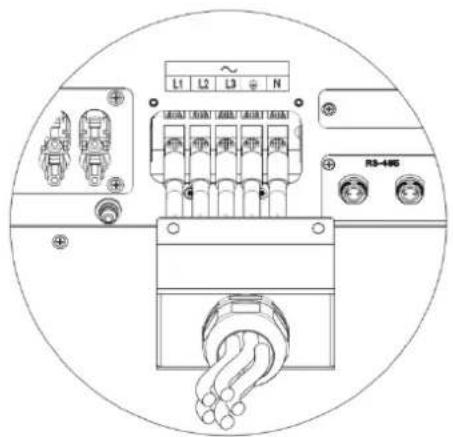
Based on the local GRID standards, it may select dierent conncon types. In the following you will find an overview of the most common type of grid structure.

text_image
TN-C grid Transformer Grid House connection Load L1 L1 L2 L2 L3 L3 PEN PEN
bar
TNS grid | Transformer | Grid | House connection | Load | |---|---|---|---| | L1 | L1 | | L1 | | L2 | L2 | | L2 | | L3 | L3 | | L3 | | N | N | | N | | PE | PE | | PE |
text_image
TN-C-S grid Transformer Grid House connection Load L1 L1 L2 L2 L3 L3 N PEN N PE
text_image
TT grid Transformer Grid House connection Load L1 L1 L2 L2 L3 L3 N N PE
text_image
IT grid Transformer Grid House connection Load L1 L1 L2 L2 L3 L3 N N PE
Information
If the output of On-grid Solar Power Generang System was connected to grid with an isolaon transformer, and the On-grid Solar Power Generang System display PV Isolaon Low error during when you start-up the On-grid Solar Power Generating System, please set the parameter "Enable Neutral" via CyberPower software 'Solar Power Setup', or
5.5.2 Compatibility Table
| Grid typeOn-gridSolar PowerGenerang System | TN-C grid | TN-S grid | TN-C-S grid | TT grid | IT grid |
| CPSPV30000ETL | Yes(N and PE of On-grid Solar Power Generang System both should connect to PEN of grid.) | Yes | Yes | Yes,if U_N-PE < 30V | No |
| CPSPV33000ETL | Yes(N and PE of On-grid Solar Power Generang System both should connect to PEN of grid.) | Yes | Yes | Yes,if U_N-PE < 30V | No |
| CPSPV40000ETL | Yes(There is no N connected required .PE of On-grid Solar Power Generang System should connect to PEN of grid.) | Yes(Le N unconnected. Because there is no terminal reserved for N point) | Yes,if U_N-PE < 30V (Le N unconnected.Because there is no terminal reserved for N point) | Yes | |
6 Commissioning
6.1 Commission the On-grid Solar Power Generang System
1) Remove all covers from the PV array.
2) Check the PV and AC voltage.
3) Plug in the PV input.
4) Turn the DC Disconnect to posion "ON"
5) If the On-grid Solar Power Generang System is connected with PV panel arrays and the input voltage is higher than 300Vdc, while the AC grid is not connected yet, LCD will display messages in order as below:
● Company info → Basic info → State info
● The LCD will display "AC V outrange "at State info and the LED turns red.
- Please check all information on the LCD, operate by knocks you will see the dierent parameters.
- Single knock to Light the backlight State info (single knock) Input info (single knock) Output info
6) Turn on the AC breaker between On-grid Solar Power Generang System and grid, the system will operate automacally.
7) Under normal operang condions, the LCD displays 'Power: xx.xx KW' at State info, this is the power feed into grid. The LED turns green.
8) Check the me and date of On-grid Solar Power Generating System as follow:
Single knock to Light the backlight State info (Thrice knock) On-grid Solar Power Generating
System info (single knock) System Time(double knock), if they are not correct, please set them, refer to Fig 6.3.15 or 6.4.3 text line.
9) Finish commissioning.
6.2 Operaon Modes
Normal Mode
In this mode, the On-grid Solar Power Generang System works normally and LED turns green.
- Whenever the DC voltage is higher than 300Vdc, On-grid Solar Power Generang System converts power to grid as generated by the PV panels;
- Whenever the DC voltage is lower than 250Vdc, the On-grid Solar Power Generang System will work in waing state and aempt to connect the grid. In waing state the On-grid Solar Power Generang System consumes just enough power generated by the PV panel to monitor the internal system.
Notes: The On-grid Solar Power Generang System starts up automatically when DC power from the PV panel is sucient.
Fault Mode
The internal intelligent controller can connuously monitor and adjust the system state. If On-grid Solar Power Generang System nds any unexpected conditions such as system fault and On-grid Solar Power Generang System fault, the fault informaon will be displayed on the LCD. In fault mode the LED turns red.
Notes: a) Detailed fault informaon refers to Chapter 9.1 ERROR messages displayed on LCD.

text_image
DC switch ON OFFb) When PV Isolation error occurred in SAA safety standard, the buzzer will give an alarm every fifteen seconds.
Shutdown Mode
On-grid Solar Power Generang System automacally stop running during periods of lile or no sunlight. In shutdown mode the On-grid Solar Power Generang System take no power from the grid and panel, and the LCD and LED turns o.
Notes: If the PV string DC voltage is too low, the On-grid Solar Power Generang System will also turn to Shutdown Mode.
Derang mode
When AC frequency is higher than 50.3Hz(settable), the On-grid Solar Power Generang System will derate its output power according to the rule.
When user set the output power limit command to the On-grid Solar Power Generang System, the On-grid Solar Power Generang System will also limit the output according to the seng.
In this derang mode, the LCD will show "DERATING".
6.3 Inial Sengs and LCD Display
In the lower right corner of On-grid Solar Power Generang System there is the LCD display. We can check On-grid Solar Power Generang System running state, historical generaon data, etc, on the LCD screen. Items displayed can be changed by knock; you can also change some On-grid Solar Power Generang System parameters by knock.
6.3.1 Inial Sengs
If it is the rst me the On-grid Solar Power Generang System starts up aer installaon, LCD will quickly switch to and stay at the grid code seng interface that is the rst seng interface of initial sengs. Only the On-grid Solar Power Generang System is completed all initial sengs, it will work and display normally. Otherwise, LCD will always stay at the 'Please select' interface.
Grid code (Country) seng
Please nish the grid code seng according to the following steps:
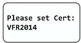
1) When at the rst interface 'Please Set Cert:' the opon is 'VFR2014' in default. By single knock, grid codes will vary from one to another, for example, 'VDE0126-1-1/A1', as Fig 6.3.1 and Fig 6.3.2
text_image
Please set Cert: VFR2014Fig 6.3.1
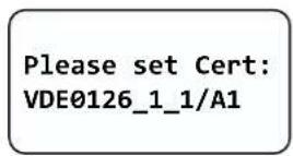
Fig 6.3.2
Note: If you have ordered the On-grid Solar Power Generang System with specific grid code sengs, the parameters have been preset in factory and you don't need to operate this step any more.
2) There are ve grid codes to select:
| 1 | VDE0126-1-1 |
| 2 | VDE0126-1-1/A1 |
| 3 | VDE0126 Taiwan |
| 4 | PEA Thailand |
| 5 | VFR 2014 |
| 6 | IEC61727+62116 |
Note: if you can't nd the grid code you want, please contact CyberPower Systems, Inc.
3) When it comes to the grid code you want, double knock to enter, as Fig 6.3.3.

Fig 6.3.3
Language seng
The second seng interface is language seng. Please nish the language seng according to the following steps:
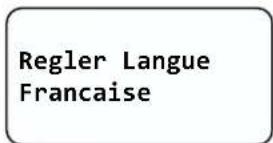
1) When at the language interface 'Set Language:' the opon is 'English' in default. By single knock, languages will vary from one to another, for example, 'Francaise', as Fig 6.3.4 and Fig 6.3.5

text_image
Set Language EnglishFig 6.3.4
text_image
Regler Langue FrancaiseFig 6.3.5
2) There are 3 languages to select:
| 1 | English |
| 2 | French |
| 3 | Chinese |
3) When it comes to the language you want, double knock to enter, as Fig 6.3.6.

text_image
Set OK! Current Language EnglishFig 6.3.6
System me seng
The last seng interface is system me seng. Please nish the system me seng according to the following steps:
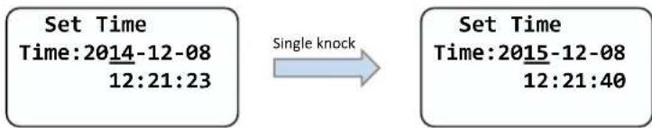
1) When at the system me interface, the me seng will start from the following sequence: Year -> Month -> Date -> Hour -> Minute. By single knock, the seng will increase 1 unit, for example, increasing 1 year, as Fig 6.3.7 and Fig 6.3.8
flowchart
graph LR
    A["Set Time\nTime:2014-12-08\n12:21:23"] -->|Single knock| B["Set Time\nTime:2015-12-08\n12:21:40"]
Fig 6.3.7
Fig 6.3.8
Note: System me will be set to current me in factory. Maybe you only need to adjust the Hour due to dierent me zone in your country.
2) By double knock, the seng will decrease 1 unit, for example, decreasing 1 year, as Fig 6.3.9 and Fig 6.3.10.

flowchart
graph LR
    A["Set Time\nTime:2015-12-08\n12:21:40"] -->|Double knock| B["Set Time\nTime:2014-12-08\n12:21:52"]
Fig 6.3.9
Fig 6.3.10
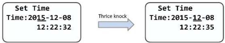
3) When nish the current sequence, thrice knock to enter and then go to next sequence, as Fig 6.3.11 and Fig 6.3.12.
flowchart
graph LR
    A["Set Time\nTime:2015-12-08\n12:22:32"] -->|Thrice knock| B["Set Time\nTime:2015-12-08\n12:22:35"]
Fig 6.3.11
Fig 6.3.12
4) When nish the Minute sequence, thrice knock to enter, as Fig 6.3.13 and Fig 6.3.14.
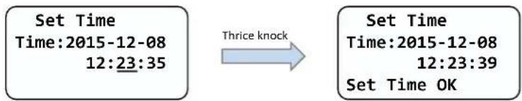
text_image
Set Time Time:2015-12-08 12:23:35 Thrice knock Set Time Time:2015-12-08 12:23:39 Set Time OKFig 6.3.13
Fig 6.3.14
5) Then, thrice knock again to nish setngs, as Fig 6.3.15. Few seconds later, system will restart and the initial sengs are completed.
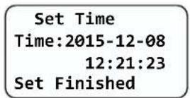
Fig 6.3.15
6.3.2 Power on Display
Power on display
Aer power on for several seconds, LCD screen will display the gure of On-grid Solar Power Generang System, company name, On-grid Solar Power Generang System power rang, etc.
text_image
CyberPower CPSPV30000ETLFig 6.3.5 On-grid Solar Power Generang System power rang
Aer 3 seconds, it will switch to the next interface. See Fig6.3.6 for reference.
VNNES20103
CPSPV30000ETL
Main Ver:XXXXXX
Comm Ver:XXXXXX
Fig6.3.6 Serial number, model name and version
Here is explanaon of items on Fig6.3.6:
● First line: Serial number of this On-grid Solar Power Generating System.
● Second line: model name of this On-grid Solar Power Generang System.
● Main Ver: rmware version of control board.
- Comm Ver: rmware version of communicaon board.
Aer displaying informaon of the third interface for 3 seconds, the background light will turn o.
LCD Display when backlight o
Aer the power on informaon is displayed automacally and the backlight turns o, the LCD display will switch to the following Interface 1. There are 4 interfaces, which can be displayed in turn by single knock.
Interface 1: Running state.
- The rst line displays On-grid Solar Power Generang System state descripon, for example, in faulty state it will display Fault and followed with faulty codes, which is convenient to compare with error code list in manual.
● The second line displays On-grid Solar Power Generang System states name.
● The third line displays energy generated today
● The fourth line displays the total energy generated since installaon.

text_image
S E EFig6.3.7 Interface 1: Running state
text_image
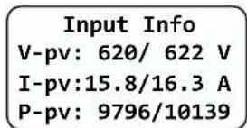
Input Info V-pv: 620/ 622 V I-pv:15.8/16.3 A P-pv: 9796/10139Fig6.3.8 Interface 2: Input informaon
Interface 2: Input informaon.
This interface displays parameters of PV input, including input voltage, current, and power of each MPP tracker.
● V-pv: input voltage of MPPT1 and MPPT2
● I-pv: input current of MPPT1 and MPPT2
● P-pv: input power of MPPT1 and MPPT2, unit is W
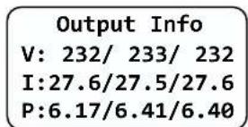
Interface 3: Output informaon. See Fig6.3.9 for reference.
This interface displays output informaon of On-grid Solar Power Generang System, including output voltage of each phase, output current of each phase, and output power of each phase.
● V: output voltage of each phase
● I: output current of each phase
● P: output power of each phase
text_image
Output Info V: 232/ 233/ 232 I:27.6/27.5/27.6 P:6.17/6.41/6.40Fig6.3.9 Interface 3: Output information
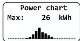
bar
| Statistic | Value | | :--- | :--- | | Max: | 26 kWh |Fig6.3.10 Interface 4: 24 hour's generaon curve
Interface 4: 24 hour's generaon curve. See Fig6.3.10 for reference.
This interface shows the generated power of every hour this day.
● Max: maximum power of today
● Power curve: today's power curve
6.3.2.3 Connecng messages
When On-grid Solar Power Generang System started to connect to grid, the following message will appear on LCD screen. See Fig6.3.11 for reference.
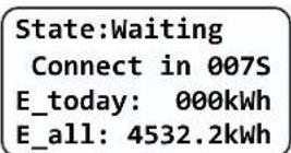
Fig6.3.11 Connect to gird interface
6.3.2.4 LCD Lock and unlock
LCD display will be locked while there is no any operaon in two minutes. You need knock four mes to unlock LCD. See Fig6.3.12 for reference.
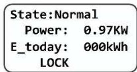
text_image
State:Normal Power: 0.97KW E_today: 000kWh LOCKFig6.3.12 Lock LCD display
6.3.3 Operate by knock
Knock type and denion
The On-grid Solar Power Generang System can support four kinds of knock: single knock, double knock, thrice knock, Knock four mes. Each kind of knock has dierent funcon. Refer to specied denion in Table 6.1.
Table 6.1 Knock denion list
| Knock type | Denion |
| Single knock | Down |
| Double knock | Enter |
| Thrice knock | Esc |
| Knock four mes | Unlock LCD |
Light backlight and single knock to check running informaon
Before light the backlight, the four types of knock funcons are the same, which is just lighng the backlight. Note that the background lighng will automatically turn o if there is no knock detected in 10 seconds.
During cloudy days or in the area of low light, it's inconvenient for users to check On-grid Solar Power Generang System running informaon such as state, input data, output data, energy generated. In this case user can light the backlight and check those data by single knock, a single knock will switch LCD screen to a following interface. The interface display on LCD screen will circle as follow: Fir6.3.7 -> Fir6.3.8 -> Fig6.3.9 -> Fig 6.3.10 -> Fig6.3.11, and then again Fig6.3.7.
6.3.4 Data checking and parameters seng
First level menu
It is a lile bit dierent to enter the rst level menu, note that using thrice knock to enter rst level menu instead of double knock. Fig 6.3.13 is the interface of rst level menu.

text_image
-->Working History Property SettingFig 6.3.13 First level menu
In current interface, a single knock will switch the index to next item, double knock will enter the corresponding second level menu.
Second level menu
In rst level menu, double knock will lead to next level menu.
The followings are second level menu interfaces for each rst level menu items, shown in Fig 6.3.14.
In second level menu, a single knock will switch the index to next item; a double knock will enter the corresponding third level menu. And a thrice knock will back to rst level menu.
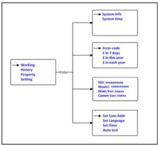
flowchart
graph TD
    A["Working History Property Setting"] --> B["Enter"]
    B --> C["→ System Info\nSystem time"]
    B --> D["→ Error code\nE in 7 days\nE in this year\nE in each year"]
    B --> E["→ NO: xxxxxxxxxxxx\nModel: xxxxxxxxxxxx\nMain Ver: xxxxx\nComm Ver: xxxxx"]
    B --> F["→ Set Com Addr\nSet Language\nSet Time\nAuto test"]
Fig 6.3.14 Second level menu for each rst level menu items
Third level menu and explanaon
Working informaon
The followings are third level menu interfaces for each second level menu items of working informaon, shown in
The followings are third level menu interfaces for each second level menu items of working informaon, shown in Fig6.3.15
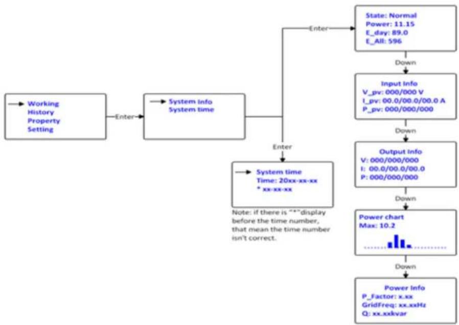
flowchart
graph TD
    A["Working History Property Setting"] -->|Enter| B["System info System time"]
    B --> C["System time Time: 20xx-xx-xx * xx-xx-xx"]
    C -->|Enter| D["State: Normal\nPower: 11.15\nE_day: 89.0\nE_All: 596"]
    D -->|Down| E["Input info\nV_pv: 000/000 V\nI_pv: 00.0/00.0/00.0 A\nP_pv: 000/000/000"]
    E -->|Down| F["Output info\nV: 000/000/000\nI: 00.0/00.0/00.0\nP: 000/000/000"]
    F -->|Down| G["Power chart Max: 10.2"]
    G -->|Down| H["Power Info\nP_Factor: x.xx\nGridFreq: xx.xxHz\nQ: xx.xxkvar"]
    C -->|Note: if there is ***display before the time number, that mean the time number isn't correct.| I
Fig 6.3.15 Third level menu interface of working informaon
Explanaons of each item in third level menu interface of working informaon:
State informaon:
Table 6.2 Working informaon sub-items explanaon
| Second level menu | Third level items | Item explanaon |
| On-grid Solar Power Generang System info | State: Normal | On-grid Solar Power Generang System running state |
| Power: xxx.xx | AC output power | |
| E_today | Energy produced today | |
| E_all | Energy produced since installaon | |
| Input info | On-grid Solar Power Generang System input parameters | |
| V_pv: xxx/xxx | PV input voltage for each MPP tracker | |
| I_pv: xx.x/xx.x | PV input current for each MPP tracker | |
| P_pv: xxxxx/xxxxxx | PV input power for each MPP tracker | |
| Output info | On-grid Solar Power Generang System output parameters | |
| V: xxx/xxx/xxx | AC output voltage for each phase | |
| I: xx.x/xx.x/xx.x | AC output current for each phase | |
| P: x.xx/x.xx/x.xx | AC output power for each phase(units:kW) |
| Second level menu | Third level items | Item explanaon |
| Power chart | Histogram of generaon power | |
| Max | Maximum output power of On-grid Solar Power Generang System | |
| Power info | Generaon power informaon of On-grid Solar Power Generang System | |
| P_Factor | Power factor | |
| GridFreq | Ulity grid frequency | |
| Q | Reacve power |
Historical informaon
Fig 6.3.16 is the third level menu interfaces for each second level menu items of historical informaon.
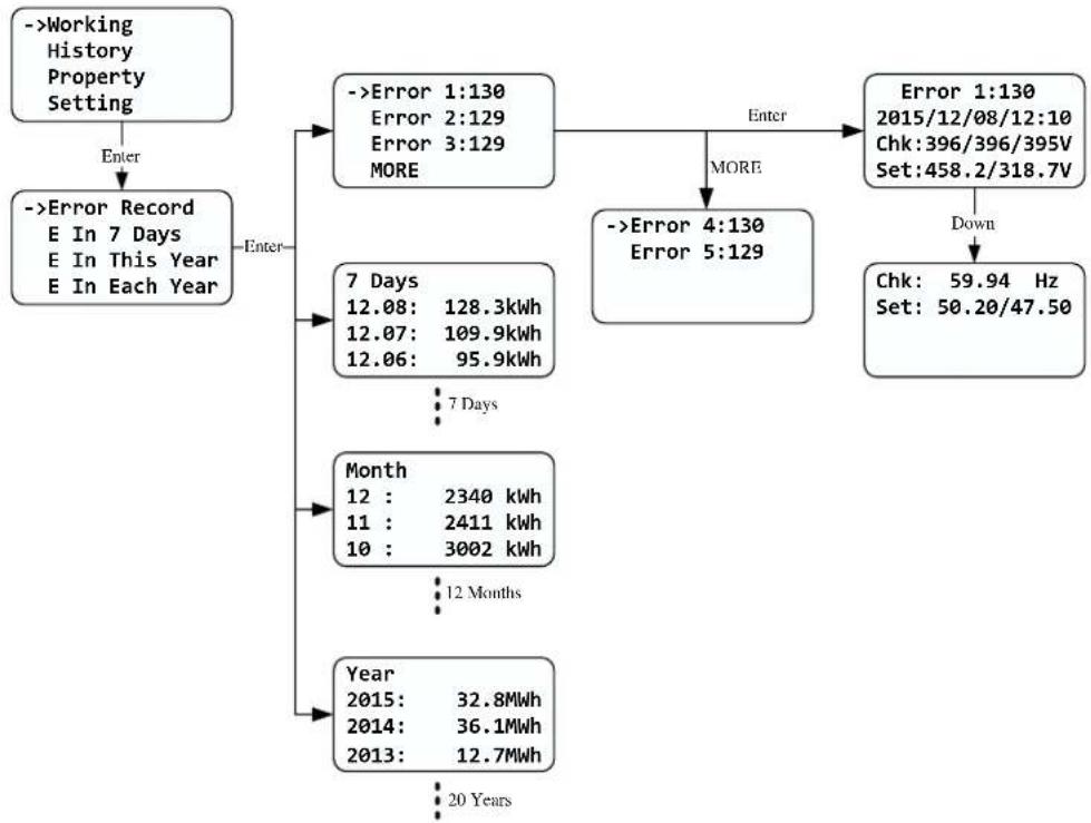
flowchart
graph TD
    A["->Working History Property Setting"] -->|Enter| B["->Error Record E In 7 Days E In This Year E In Each Year"]
    B --> C{Enter}
    C --> D["->Error 1:130 Error 2:129 Error 3:129 MORE"]
    D --> E{Enter}
    E --> F["->Error 4:130 Error 5:129"]
    F --> G{More}
    G --> H["->Error 1:130 2015/12/08/12:10 Chk:396/396/395V Set:458.2/318.7V"]
    H --> I["Down"]
    I --> J["Chk: 59.94 Hz Set: 50.20/47.50"]
    D --> K["7 Days 12.08: 128.3kWh 12.07: 109.9kWh 12.06: 95.9kWh"]
    K --> L["7 Days"]
    L --> M["Month 12 : 2340 kWh 11 : 2411 kWh 10 : 3002 kWh"]
    M --> N["12 Months"]
    N --> O["Year 2015: 32.8MWh 2014: 36.1MWh 2013: 12.7MWh"]
    O --> P["20 Years"]
Fig 6.3.16 Third level menu interface of historical informaon
Explanaon of each item in third level menu interface of working informaon: State informaon:
Table 6.3 Historical informaon sub-items explanaon
| Second level menu | Third level items | Item explanaon |
| Error Record | Error1: xxx | Five latest error records |
| Error2: xxx | ||
| Error3: xxx | ||
| Error4: xxx | ||
| Error5: xxx | ||
| More | More error record | |
| Second level menu | Third level items | Item explanaon |
| E in 7 Days | 7 Days | Title indicates this is latest 7 days running data |
| MM:DD: xxx.x kWh | Format is Month:Date, xxxx.x is energy generated in that day. | |
| E in Each Month | Month | Title indicates this is every month's running data in this year. |
| MM: xxxxx kWh | xxxx.x is energy generated in that month. | |
| E in Each Year | Year | Title indicates this is latest 10 years running data. |
| 20XX: xxxx.x Mwh | xxxx.x is energy generated in the corresponding year. |
Property informaon
Fig 6.3.17 is the second level menu interfaces of property

flowchart
graph LR
    A["Working History ->Property Setting"] -->|Enter| B["VNNES20103 CPSPV30000ETL Main Ver:XXXXXX Comm Ver:XXXXXX"]
Fig 6.3.17 Property informaon
Explanaon of each item in third level menu interface of working informaon:
State informaon:
| First level menu | Second level items | Item explanaon |
| Property | VANNES20103 | Serial number of this On-grid Solar Power Generang System. |
| CPSPV30000ETL | Model name of this On-grid Solar Power Generang System. | |
| Main Ver:xxxxxx | Firmware version of Control Board | |
| Comm Ver:xxxxxx | Firmware version of Communicaon Board |
Parameters set
Fig 6.3.18 is the seng informaon in second level menu.

flowchart
graph TD
    A["Working History Property -->->Setting"] -->|Enter| B["PLEASE INPUT:123 INPUT:0**"]
    B -->|Enter| C["->Set Time\nSet Language\nSet Com Addr\nSet GroundKit"]
    C --> D["->Set Year\nSet Month\nSet Day\nMORE"]
    D -->|Enter| E["->Year Up\nYear Down"]
    E --> F["->Year Up\n2014-12-08\n12:21:23"]
    F -->|Down| G["Year Up\n2015-12-08\n12:21:23"]
    G --> H["->Set Hour\nSet Minute"]
    H --> I["->Set Year\nSet Month\nSet Day\nMORE"]
    I -->|More| J["->Set Time\nSet Language\nSet Com Addr\nSet GroundKit"]
    J --> K["->Set Year\nSet Month\nSet Day\nMORE"]
    K --> L["->Year Up\nYear Down"]
    L --> M["->Year Up\n2014-12-08\n12:21:23"]
    M --> N["->Year Up\n2015-12-08\n12:21:23"]
    N --> O["->Set Year\nSet Month\nSet Day\nMORE"]
    O --> P["->Year Up\nYear Down"]
    P --> Q["->Year Up\n2014-12-08\n12:21:23"]
    Q --> R["->Year Up\n2015-12-08\n12:21:23"]
    R --> S["->Year Up\n2015-12-08\n12:21:23"]
    S --> T["->Year Up\n2015-12-08\n12:21:23"]
    T --> U["->Year Up\n2015-12-08\n12:21:23"]
    U --> V["->Year Up\n2015-12-08\n12:21:23"]
    V --> W["->Year Up\n2015-12-08\n12:21:23"]
    W --> X["->Year Up\n2015-12-08\n12:21:23"]
    X --> Y["->Year Up\n2015-12-08\n12:21:23"]
    Y --> Z["->Year Up\n2015-12-08\n12:21:23"]
    Z --> AA["->Year Up\n2015-12-08\n12:21:23"]
    AA --> AB["->Year Up\n2015-12-08\n12:21:23"]
    AB --> AC["->Year Up\n2015-12-08\n12:21:23"]
    AC --> AD["->Year Up\n2015-12-08\n12:21:23"]
    AD --> AE["->Year Up\n2015-12-08\n12:21:23"]
    AE --> AF["->Year Up\n2015-12-08\n12:21:23"]
    AF --> AG["->Year Up\n2015-12-08\n12:21:23"]
    AG --> AH["->Year Up\n2015-12-08\n12:21:23"]
    AH --> AI["->Year Up\n2015-12-08\n12:21:23"]
    AI --> AJ["->Year Up\n2015-12-08\n12:21:23"]
    AJ --> AK["->Year Up\n2015-12-08\n12:21:23"]
    AK --> AL["->Year Up\n2015-12-08\n12:21:23"]
    AL --> AM["->Year Up\n2015-12-08\n12:21:23"]
    AM --> AN["->Year Up\n2015-12-08\n12:21:23"]
    AN --> AO["->Year Up\n2015-12-08\n12:21:23"]
    AO --> AP["->Year Up\n2015-12-08\n12:21:23"]
    AP --> AQ["->Year Up\n2015-12-08\n12:21:23"]
    AQ --> AR["->Year Up\n2015-12-08\n12:21:23"]
    AR --> AS["->Year Up\n2015-12-08\n12:21:23"]
    AS --> AT["->Year Up\n2015-12-08\n12:21:23"]
    AT --> AU["->Year Up\n2015-12-08\n12:21:23"]
    AU --> AV["->Year Up\n2015-12-08\n12:21:23"]
    AV --> AW["->Year Up\n2015-12-08\n12:21:23"]
    AW --> AX["->Year Up\n2015-12-08\n12:21:23"]
    AX --> AY["->Year Up\n2015-12-08\n12:21:23"]
    AY --> AZ["->Year Up\n2015-12-08\n12:21:23"]
    AZ --> BA["->Year Up\n2015-12-08\n12:21:23"]
    BA --> BB["->Year Up\n2015-12-08\n12:21:23"]
    BB --> BC["->Year Up\n2015-12-08\n12:21:23"]
    BC --> BD["->Year Up\n2015-12-08\n12:21:23"]
    BD --> BE["->Year Up\n2015-12-08\n12:21:23"]
    BE --> BF["->Year Up\n2015-12-08\n12:21:23"]
    BF --> BG["->Year Up\n2015-12-08\n12:  0** "]
    BG --> BH["->Year Up\n         -    -    -    -    -    -    -    -    -    -    -    -    -    -    -    -    -    -    -    -    -    -    -    -    -    -    -    -    -    -    -    -    -    -    <br>    AY --> BI[->Current Addr COM Addr Up CoM Addr Down"]
    BI --> BJ["->Current Addr COM Addr Up CoM Addr Down"]
    BJ --> BK["->Current Addr COM Addr Up CoM Addr Down"]
    BK --> BL["->Current Addr COM Addr Up CoM Addr Down"]
    BL --> BM["->Current Addr COM Addr Up CoM Addr Down"]
    BM --> BN["->Current Addr COM Addr Up CoM Addr Down"]
    BN --> BO["->Current Addr COM Addr Up CoM Addr Down"]
    BO --> BP["->Current Addr COM Addr Up CoM Addr Down"]
    BP --> BQ["->Current Addr COM Addr Up CoM Addr Down"]
    BQ --> BR["->Current Addr COM Addr Up CoM Addr Down"]
    BR --> BS["->Current Addr COM Addr Up CoM Addr Down"]
    BS --> BT["->Current Addr COM Addr Up CoM Addr Down"]
    BT --> BU["->Current Addr COM Addr Up CoM Addr Down"]
    BU --> BV["->Current Addr COM Addr Up CoM Addr Down"]
    BV --> BW["->Current Addr COM Addr Up CoM Addr Down"]

    CA["->Disable Enable Set success"] --> CB["->Disable Enable Set success"]
Fig 6.3.18 seng second level menu and its sub-menus
Set On-grid Solar Power Generang System COM address
When communicating with monitoring soware or device, the soware or device may regard On-grid Solar Power Generang System COM address as communicaon address (Also may use On-grid Solar Power Generang System serial number as communicaon address). The COM address could be assigned. The second level menu “Set COM Addr” of seng is to set On-grid Solar Power Generang System COM address.
Seng steps:
Input password->Seng->Set COM addr->Set Manual, "Current Addr" is the current address of On-grid Solar Power Generang System. "COM Addr Up" adds address. "COM Addr Up" decreases address. Single knock to change value of xed address, double knock enter next manual. Choose "YES" to save changes, and LCD screen will display "Set Addr OK! Current Addr XXX".
Set language
To change On-grid Solar Power Generang System displaying language, please select Seng->Set language, then LCD screen will display current language type, single knock to change current language, double knock will save changes and displays “Set Language OK! Current Language English” see Fig 6.3.6 for reference.
Please note in order to prevent disoperation, system language won't be change in second level menu "Set language", but it will be only if user saves save the choice by double knock and LCD displays "Set OK!"
The On-grid Solar Power Generang System provides three languages: English, French and Chinese. The number on Set language interface is sequence number of these three languages, the sequence number and its corresponding language are shown in Table6.5.
Table6.5 sequence number of languages
| Language | Sequence Number |
| English | 0 |
| French | 1 |
| Chinese | 2 |
Set On-grid Solar Power Generang System me
On-grid Solar Power Generating System provides a system clock; user must set the system me aer installaon, as the historical stasc data for a period were based on the clock. User can set the following me parameters: year, month, day, hour, minute.
Set year: Seng->Set me->Set year->Year up or Year down->knock to change year. Thrice knock to exit and save changes.
Set month: Seng->Set me->Set month->Month up or Month down->knock to change month. Thrice knock to exit and save changes.
Set date: Seng->Set me->Set date->Date up or Date down->knock to change date. Thrice knock to exit and save changes.
Set hour: Seng->Set me->Set hour->Hour up or Hour down->knock to change Hour. Thrice knock to exit and save changes.
Set minute: Seng->Set me->Set minute->minute up or minute down->knock to change minute. Thrice knock to exit and save changes.
6.4 Double MPPT of the CPS Mini Central
The CPS Mini Central includes dual input secon to process eight strings with independent MPPT, high speed and precise MPPT algorithm for real-me power tracking and energy harvesng, as well as transformerless operaon for high performance, the max conversion eciency is up to 98.2%. The wide input voltage range makes the On-grid Solar Power Generang System suitable to low power operaon as well as the high power operaon.
As the weather inuence and the locaon of two MPPT PV arrays dierent, the power of the MPPT A inputs is dierent from the power inputs of the MPPT B at the same me, the CPS Mini Central works at a non-symmetrical input state. But the MPPT algorithm of the On-grid Solar Power Generang System makes it tracking the maximum power point of each MPPT channel to improve the energy ulizaon of the PV arrays.

line
| U(v) | Current(A) | Power(W) | |------|------------|----------| | 0 | Isc | 0 | | Vm | Mpp | Im | | Voc | 0 | 0 |6.5 Communicaon
6.5.1 Using 'Solar Power Setup\_3P' to Update rmware & monitor On-grid Solar Power Generang System
About the soware -Solar Power Setup_3P, please download from CyberPower ocial website. For more detail informaon about rmware upgrade, please refer to service manual or contact with CyberPower System, Inc.
The connecng diagram as follow:
If you want to update rmware online, please disconnect AC breaker of the On-grid Solar Power Generang System rst.
6.5.2 Monitor the On-grid Solar Power Generang System
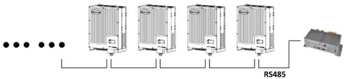
The On-grid Solar Power Generang System provides RS232/RS485 interface to communicate with remote PC or logger. User can monitor the On-grid Solar Power Generang System state via the following types of communicaon systems. For more detail informaon, please contact with CyberPower Systems, Inc.
- Monitor the On-grid Solar Power Generang System through RS485 interface with soware "Solar Power Monitoring".
- Monitor the On-grid Solar Power Generang System through RS485 interface with "CPS Data Logger" for cloud applicaon.
flowchart
graph LR
    A["..."] --> B["Heat Exchangers"]
    B --> C["RS485"]
    C --> D["Terminal Module"]
- CPS Mini Central series On-grid Solar Power Generang System are compatible with Solar-Log 200/500/1000.
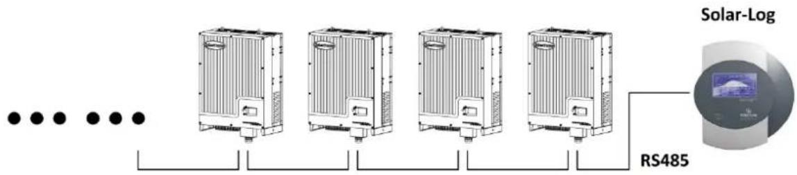
text_image
Solar-Log RS485- CPS Mini Central series On-grid Solar Power Generang System are compatible with "Meteocontrol WEB'log" series.

flowchart
graph LR
    A["..."] --> B["Heat Exchangers"]
    B --> C["..."]
    B --> D["..."]
    B --> E["..."]
    B --> F["..."]
    B --> G["..."]
    B --> H["..."]
    B --> I["..."]
    B --> J["RS485"]
6.5.3 RS485 cable conncon
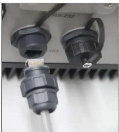
- To find out the assembly parts for water-proof RJ45 in the package of accessory, like the following pic.

natural_image
Disassembled black plastic mechanical component with multiple cylindrical and ring features, no visible text or symbols- To stump the rubber seal on the head of plug for waterproof.

natural_image
Two views of a black plastic pipe fitting, one showing internal threading and the other showing threaded end (no text or symbols)- To pull the RS485 cable through the RJ45 components, before crimping connector of CAT-5e or CAT-6 onto the RJ45 crystal connector.

natural_image
Close-up of a blue and black plastic electrical connector with multiple ports (no text or symbols visible)- The connection between crystal connectors and RS485 cable is one-to-one correspondence, one pin of crystal connector to one specific color wire, as shown in the following table and picture.
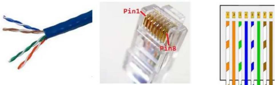
text_image
Pin1 Pin8 1 2 3 4 5 6 7 8Pin Definition of RJ45 for RS485 protocol
| Pin1---- NC | PIN 1 → 8 |
| Pin2---- NC | |
| Pin3---- B/TRX- | |
| Pin4---- A/TRX+ | RJ45 SOCKET |
| Pin5---- NC | PIN 8 → 1 |
| Pin6---- NC | |
| Pin7---- NC | |
| Pin8---- NC | RJ45 PLUG |
| Pins of crystal connector | Color of each RS485 cable |
| 1 | Orange and white |
| 2 | Orange |
| 3 | Green and white |
| 4 | Blue |
| 5 | Blue and white |
| 6 | Green |
| 7 | Brown and white |
| 8 | Brown |
- To crimp cable on RJ45 crystal connector then push the connector into water-proof plug.

natural_image
Close-up of a USB connector showing internal socket and cable assembly (no text or symbols visible)- To seal the cable by tightening the end screw of cable gland.

natural_image
Close-up of a gray electrical connector with visible internal components and a blue cable (no text or symbols)
Information
Before you connect the RJ45 crystal connector to the On-grid Solar Power Generating System, we are recommending you use the professional tool to check whether the cable is well fixed and working.
- P
lease open the RJ45 protection cover of the RJ45 socket on On-grid Solar Power Generating System and connect the RJ45 crystal connector in the On-grid Solar Power Generating System port.
- To tighten the front screw of RJ45 plug onto the socket for water-proof.
natural_image
Close-up of a mechanical component with two connectors and a screw, no visible text or symbols
natural_image
Close-up of two electrical connectors with visible wiring and a screw head (no text or symbols)
Information
Pull cables outwards to conrm whether the installaon rm or not.
7 Start-Up and shut down the On-grid Solar Power Generang System
7.1 Start-Up the On-grid Solar Power Generang System
- Turn on the AC grid breaker;
- Turn on the DC switch of the On-grid Solar Power Generang System, and the On-grid Solar Power Generang System will start automacally when the input voltage is higher than 300V.
7.2 Shut down the On-grid Solar Power Generang System
- Turn o the AC grid breaker;
- Turn o the DC switch of the On-grid Solar Power Generang System.
- Check the On-grid Solar Power Generang System operang state.
- Unl the display of LCD goes out, the On-grid Solar Power Generang System is shut down.
8 Maintenance and Cleaning
Once the output power is derang because of too high warming, some ps can help you solve such problems:
- The air grills or cooling fans are clogged. To clean the air grills and cooling fans please refer to 8.1 Cleaning Fans and Grills.
● One or two cooling fans failed. To exchange the cooling fans please refer to 8.2 Exchanging Fans. - Venlaon of installaon locaon is poor. Choose appropriate installaon locaon before moung.
8.1 Cleaning Fans and Grills
Maintain fans and grills every half a year to reduce the power derang caused by excessive heat.
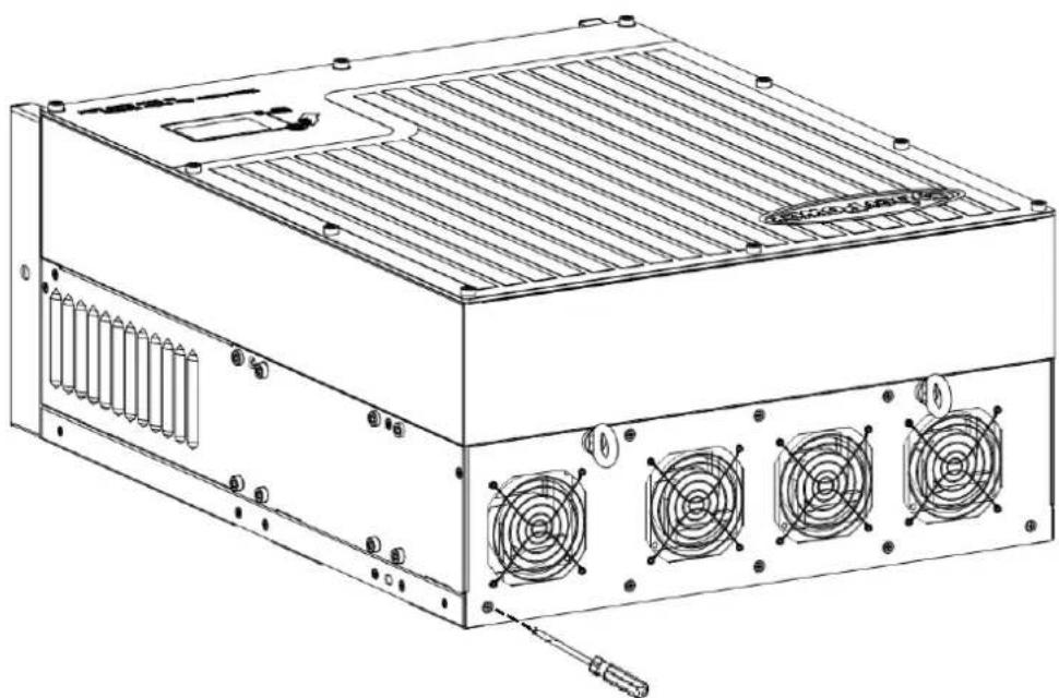
If fans or grills are just covered by so dust parcles, using tools such as vacuum cleaner to clean the fans. And if user has no such tools or there are obstrucons in fans, grills or the cooling area of On-grid Solar Power Generang System, you need to clean the fans and grills aer they are took apart from the On-grid Solar Power Generang System.
-
Please disconnect the DC and AC conncon.
-
Turn o the DC switch.
- Disconnect the DC terminal. (You might need some tool to disconnect the male and female terminals)
-
Disconnect the AC terminal.
-
Remove the protecting plants at the boom of On-grid Solar Power Generang System.
Remove the On-grid Solar Power Generang System from moung bracket, and place On-grid Solar Power Generang System horizontally on clean and dry place.
- Screw o the screws to open the cover with suitable tool, then fans will be seen, as gures below:
natural_image
Technical line drawing of a computer power supply unit with cooling fans and ventilation slots (no text or labels)Fig 8.1.5
- Pull out the white connectors with some tinny tools.

natural_image
Diagram of a mechanical assembly with three components and a magnified inset showing internal components (no text or labels)Fig 8.1.6
- Take away the fans from the cover and clean them thoroughly.

natural_image
Diagram of a four-f合一 rack-mounted fan with a screwdriver inserted, no text or symbols present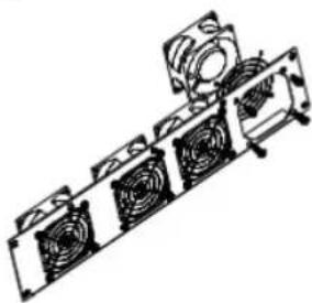
natural_image
Technical line drawing of a mechanical assembly with multiple fans and a cylindrical component (no text or symbols)Fig.8.1.7
- When finishing cleaning, put back the fans in reverse order.
9 Trouble shooting
Our quality control program assures that every On-grid Solar Power Generating System is manufactured to accurate specifications and is thoroughly tested before leaving our factory. If you have difficulty in the operation of your On-grid Solar Power Generating System, please read through the following information to correct the problem.
9.1 Error Messages displayed on LCD
An error message will be displayed on the LCD screen when a fault occurs. The faults consist of system fault and On-grid Solar Power Generating System fault.
You may be advised to contact CyberPower in some situation, please provide the following information.
Information concerning the On-grid Solar Power Generating System:
- Serial number
● Model number - Error message on LCD
● Short description of the problem
Grid voltage - DC input voltage
● Can you reproduce the failure? If yes, how?
● Has this problem occurred in the past?
● What was the ambient condition when the problem occurred?
Information concerning the PV panels:
9.1.1 System fault
System fault (system faults are mainly caused by system instead of On-grid Solar Power Generating System, please check the items as instructed below before replacing On-grid Solar Power Generating System).
| Error message | Description | Suggestion |
| ACV Outrange | Utility grid voltage is out of permissible range. | 1. Check grid voltage.2. Check AC wiring, especially the ground wire.3. If the error message still exists despite the grid voltage being within the tolerable range, contact CyberPower. |
| ACF Outrange | Utility grid frequency out of permissible range. | 1. Check AC wiring and grid frequency.2. If the error message is displayed despite the grid frequency being within the tolerable range, contact CyberPower |
| PV Isolation Low | Insulation problem. | 1. Check if panel enclosure ground properly.2. Check if On-grid Solar Power Generating System ground properly.3. Check if the DC breaker gets wet.4. Check the impedance of PV (+) & PV (-) between ground (must be more than 1 M). If the error message is displayed despite the above checking passed, contact CyberPower. |
| Residual I High | Leakage current too high. | 1. Restart On-grid Solar Power Generating System2. If error message still exists, contact CyberPower. |
| Output High DCI | Output current DC offset too high. | 1. Restart On-grid Solar Power Generating System.2. If error message still exists, contact CyberPower. |
| 2. Turn o dc switch, rotate fan blade with screwdriver, and then restart On-grid Solar Power Generang System.3. If Warning sll exist, Contact CyberPower. | ||
| Warning104 | Firmware version does not match. | 1. Restart the On-grid Solar Power Generang System.2. If Warning sll exist, Contact CyberPower. |
9.1.3 On-grid Solar Power Generang System fault
| Error code | Meanings | Suggeson |
| Error: 101 | Communicaon board has not received data from control board for 10 seconds. Electromagnec Interference cause communicaon problem. | 1. Restart On-grid Solar Power Generang System by cung o DC supply, and Error message will disappear.2. If the error 101 is oen displayed, the environment Electromagnec Interference is too strong. Contact CyberPower. |
| Error: 117 | Relay fault. | Restart On-grid Solar Power Generang System, if problem sll exist, Contact CyberPower. |
| Error: 119 | GFCI module fault.(Ground Fault Circuit Interrupter) | Restart On-grid Solar Power Generang System, if problem sll exist, Contact CyberPower. |
| Error: 121 | Communicaon fault. | Restart On-grid Solar Power Generang System, if problem sll exist, Contact CyberPower. |
| Error: 122 | Bus voltage fault. | Restart On-grid Solar Power Generang System, if problem sll exist, Contact CyberPower. |
| Error: 125 | PV ISO fault.(Low isolaon) | 1. Refer the suggeson of error “PV Isolaon Low”.2. If problem sll exist, Contact CyberPower. |
| Error: 126 | High GFCI | Restart On-grid Solar Power Generang System, if problem sll exist, Contact CyberPower. |
| Error: 127 | High DCI | 1. Refer the suggeson of error “Output High DCI”.2. If problem sll exist, Contact CyberPower. |
| Error: 128 | High PV voltage | 1. Refer the suggeson of error “PV Voltage High”.2. If problem sll exist, Contact CyberPower. |
| Error: 129 | Grid voltage fault. | 1. Refer the suggeson of error “AC V Outrange”.2. If problem sll exist, Contact CyberPower. |
| Error: 130 | Grid frequency fault. | 1. Refer the suggeson of error “AC F Outrange”.2. If problem sll exist, Contact CyberPower. |
10 Decommissioning
10.1 Dismantling the On-grid Solar Power Generang System
- Disconnect the On-grid Solar Power Generang System as described in secon 7.
- Remove all conncon cables from the On-grid Solar Power Generang System.

CAUTION
Danger of burn injuries due to hot enclosure parts!
Wait 20 minutes before disassembling until the housing has cooled down.
- Screw o all projecng cable glands.
- Li the On-grid Solar Power Generang System o the bracket and unscrew the bracket screws.
10.2 Packing the On-grid Solar Power Generang System
If possible, always pack the On-grid Solar Power Generang System in its original carton and secure it with tension belts. If it is no longer available, you can also use an equivalent carton. The box must be capable of being closed completely and made to support both the weight and the size of the On-grid Solar Power Generang System.
10.3 Disposing of the On-grid Solar Power Generang System

Do not dispose of faulty On-grid Solar Power Generating System or accessories together with household waste. Please accordance with the disposal regulaons for electronic waste which apply at the installaon site at that me. Ensure that the old unit and, where applicable, any accessories are disposed of in a proper manner.
11 Specicaon
11.1 Specicaon of CyberPower Mini Central Series
| CPSPV30000ETL | CPSPV33000ETL | CPSPV40000ETL | |
| Input (DC) | |||
| Max. DC power | 34500 W | 36300 W | 44000 W |
| Max. input voltage | 1000 V | 1000 V | 1000 V |
| MPP voltage range / Rated input voltage | 460...800 V / 600 V | 460...800 V / 600 V | 550...800 V / 700 V |
| Min. input voltage / initial input voltage | 250/300 V | 250/300 V | 250/300 V |
| Max. input current | 35/35 A | 38/38 A | 38/38 A |
| Number of MPP input / strings per MPP input | 2 / 4 | 2 / 4 | 2 / 4 |
| Output (AC) | |||
| Rated AC power | 30000 W | 33000 W | 40000 W |
| Max apparent AC power | 30000 VA | 33000 VA | 40000 VA |
| Max. output current | 45.5 A | 50.0 A | 50.0 A |
| Nominal AC voltage | 3/N/PE, 220/380 V, 230/400 V, 240/415 V | 3/PE, 277/480 V | |
| Rated frequency | 50 Hz, 60 Hz | ||
| Cos phi | 0.9 over-excited ... 0.9 under-excited | ||
| Feed-in phases | 3 | ||
| Efficiency | |||
| Max efficiency | 98.2 % | 98.2 % | 98.2 % |
| Euro-eta | 97.6 % | 97.7 % | 97.8 % |
| MPPT efficiency | 99.5 % | 99.5 % | 99.5 % |
| General Data | |||
| Dimensions(W/H/D) | 551/740/276 mm | ||
| Weight | 61.6kg | ||
| Operating temperature | -20 °C ... +60 °C | ||
| Storage temperature | -20 °C ... +70 °C | ||
| Noise emission | ≤ 55 dB(A) | ||
| Night consumption | <0.5 W | ||
| Topology | Transformer-less | ||
| Cooling concept | Smart cooling | ||
| Protection Class | IP65 | ||
| Relative humidity | 0...100 % (non-condensing) | ||
| Features | |||
| DC connection | H4/MC4(opt) | H4/MC4(opt) | H4/MC4(opt) |
| AC connection | Screw terminal | Screw terminal | Screw terminal |
| Display | LCD | LCD | LCD |
| RS232/RS485 | yes/yes | yes/yes | yes/yes |
| Warranty: 5/10 years | yes /opt | yes /opt | yes /opt |
| Certificates | VDE 0126-1-1, VDE 0126-1-1/A1, VFR 2014CE, IEC 62109EN61000-6-2 / EN61000-6-3 / EN61000-3-11 /EN61000-3-12 | ||
11.2 Torque Values
| Enclosure lid screws | 1.3Nm(10.8 1bf.in) |
| Shell and RS232 screws | 0.7Nm(6.2 1bf.in) |
| AC terminal | 1.8Nm(16.0 1bf.in) |
| M6 socket head cap screws for securing the enclosure at the bracket | 2Nm(18 1bf.in) |
| Additional ground screws | 2Nm(18 1bf.in) |
| Fans screws | 1Nm(9.0 1bf.in) |
12 Cercates
CPS Mini Central series On-grid Solar Power Generang System are designed to use worldwide, hence the On-grid Solar Power Generang System meet dierent safety standards of variety countries and regions.
| Model | Cercates |
| CPSPV30000ETL | IEC 62109, VDE0126-1-1, VDE0126-1-1/A1, VFR 2014, CE |
| CPSPV33000ETL | IEC 62109, VDE0126-1-1, VDE0126-1-1/A1, VFR 2014, CE |
| CPSPV40000ETL | IEC 62109, VDE0126-1-1, VDE0126-1-1/A1, VFR 2014, CE |
13 Contact
If you have technical problems concerning our products, contact your installer or CyberPower. During inquiring, please provide below informaon:
- On-grid Solar Power Generang System type
- Modules informaon
- Communicaon method
- Serial number of On-grid Solar Power Generang System
- Error code of On-grid Solar Power Generang System
- Display of On-grid Solar Power Generang System
CyberPower Systems, Inc.
6F, No.32, Sec.1, Chenggong Rd.,
Nanggang District, Taipei 115, Taiwan (R.O.C.)
Serviceline
TEL: +886-2-2651-8699
FAX: +886-2-2651-6821
E-mail: service@cpsww.com.tw