KATVFSW65LM - Washing machine Kogan - Free user manual and instructions
Find the device manual for free KATVFSW65LM Kogan in PDF.

User questions about KATVFSW65LM Kogan
0 question about this device. Answer the ones you know or ask your own.
Ask a new question about this device
Download the instructions for your Washing machine in PDF format for free! Find your manual KATVFSW65LM - Kogan and take your electronic device back in hand. On this page are published all the documents necessary for the use of your device. KATVFSW65LM by Kogan.
USER MANUAL KATVFSW65LM Kogan
natural_image
Line drawing of a tripod-mounted stand with two horizontal plates and a cylindrical base (no text or symbols)SOLID WOOD TV FLOOR STAND
(SUITABLE FOR 45-65" TVS)
KATVFSW65LM
SAFETY & WARNINGS
Read the entire user guide before you start installation and assembly. If you have any questions regarding any of the instructions or warnings, contact your local distributor for assistance.
CAUTION: Use with products heavier than the rated weights indicated may result in instability causing possible injury.
- Please closely follow the assembly instructions. Improper installation may result in damage or serious personal injury.
- Safety gear and proper tools must be used. This product should only be installed by professionals.
- This product includes an anti-tip kit that must be used in conjunction with the product and will prevent the unit from falling or tipping over. Follow the enclosed information to properly install these safety accessories.
- This product is designed to be installed on solid concrete walls, masonry walls or wood stud walls.
- Make sure that the supporting surface will safely support the combined weight of the equipment and all attached hardware and components.
- Use the mounting screws provided and DO NOT OVER TIGHTEN mounting screws.
- This product contains small items that could be a choking hazard if swallowed. Keep these items away from children.
- This product is intended for indoor use only. Using this product outdoors could lead to product failure and personal injury.
- Never exceed the maximum load capacity of 50kg or it may result in product failure or personal injury.
IMPORTANT: Ensure that you have received all parts according to the component checklist prior to installation. If any parts are missing or faulty, contact your place of purchase for a replacement.
MAINTENANCE: Check that the product is secure and safe to use at regular intervals (at least every three months).
VESA Compatible
200x200 300x200
400x200 300x300
400x300 400x400

COMPONENTS
A (x1)
B (x2)
C (x1)

D (x1)
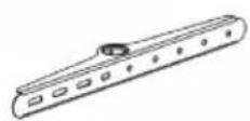
E Upper bracket (x1)
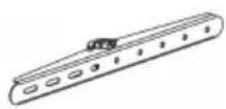
F Lower bracket (x1)

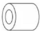
G Plastic cover (x1)

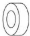
H Locking collar (x1)

I M6x70 Screw (x3)
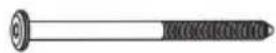
J M6x90 Screw (x1)
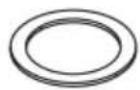
K D45.5 Washer (x1)
L M6x30 Screw (x1)

M 4mm
Allen Key (x1)

M-A M6x14 Screw (x4)
M-B M8x16 Screw (x4)
M-C M6x30 Screw (x4)

M-D M8x35 Screw (x4)
M-E D8 Washer (x4)
M-F Spacer (x4)
M-G Spacer (x4)
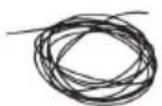
P-A Anti-fall rope (x1)
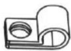
P-B Cable clips (x2)

P-C Anti-fall bracket (x1)

P-D Rope screw (x2)

P-E ST4.8x38 Screw (x1)

P-F Wall Anchor (x1)

P-G D5 Washer (x2)
ASSEMBLY
Step 1:

text_image
Technical diagram illustrating a mechanical assembly with labeled components (A, B, C, D) and a magnified inset showing a component with rotational motion.Step 2:
Loosen the screw and insert part A into part C.

text_image
C AStep 3:
- Attach the two assemblies together and secure them in place using an M6x70 Screw (I).
- Cover the screw with the plastic cover (G). Note: To remove the plastic cover, press the right side in until the cover pops out.

text_image
Technical diagram illustrating the step-by-step assembly of a mechanical component, showing pin alignment and tool application.Step 4:
Ensure the fastener is vertical and insert a M6x90 Screw (J) into the assembly.
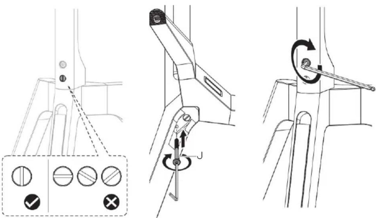
text_image
Technical diagram illustrating three-step assembly steps for a mechanical device, including adjustment controls and rotation mechanism.Step 5:
- Attach the locking collar (H) to the assembly and secure it into position using the M6x30 Screw (L).
- Place the D45.5 Washer (K) onto the stand.
Note: Ensure the screw is properly threaded into the hole. The locking collar must be in position before attaching a TV to the stand.

text_image
Technical diagram illustrating a mechanical assembly with labeled parts H, K, and L, showing a lever mechanism and close-up of the component.Step 6:
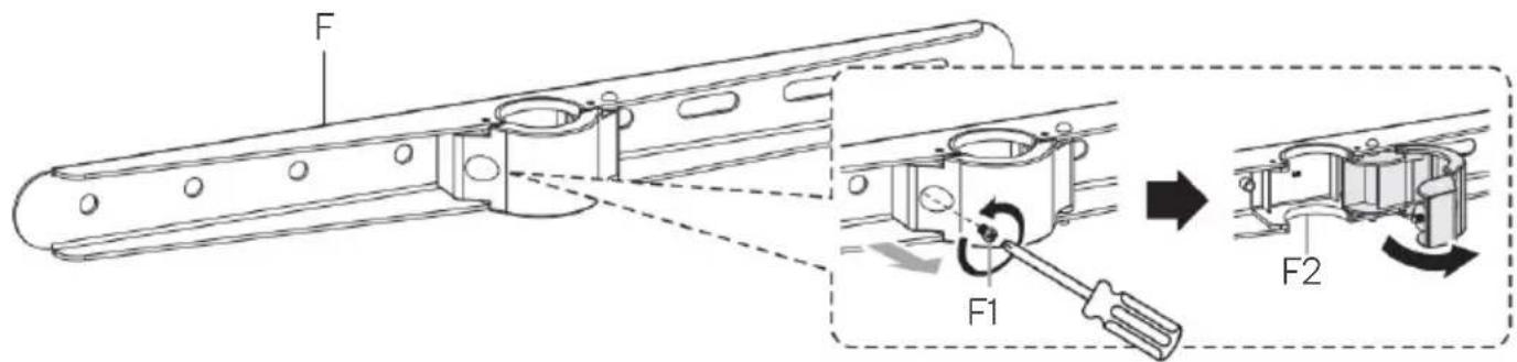
text_image
F F1 F2Step 7:
- Attach the brackets (E & F) to the rear of the TV and secure them in place using the supplied screws ("M-" set) and washers (M-E).
- The cable clips (P-B) will need to be attached to the upper bracket (E).
Note: Depending on your TV you may need to install the spacers (M-F & M-G).

text_image
M-A P-B M-E M-B P-B M-E E F TOP Too long Too Short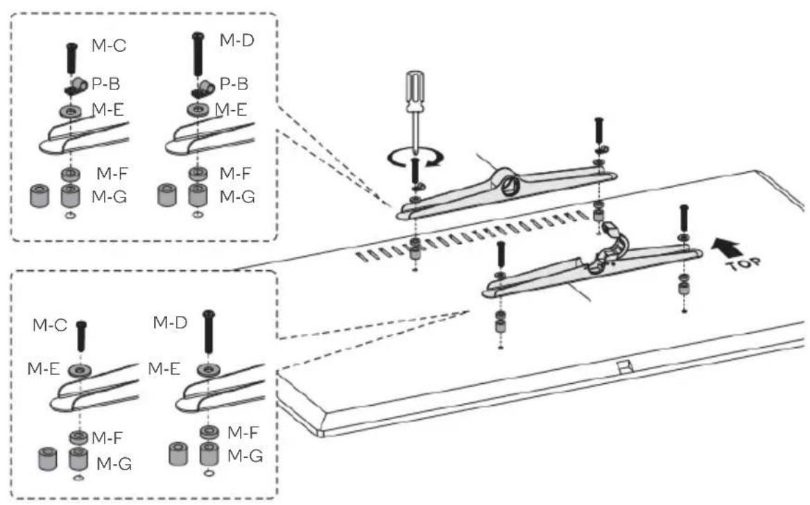
text_image
M-C P-B M-E M-F M-G M-D P-B M-E M-F M-G TOP M-C M-E M-D M-E M-F M-G M-F M-GStep 8:
- Carefully attach the TV to the stand. Enlist the help of a second person to safely carry the TV.
- Close the clasp on the lower bracket (F) and tighten the screw (F1).
Note: Ensure there is at least 20mm clearance between the bottom of the TV and the stand.

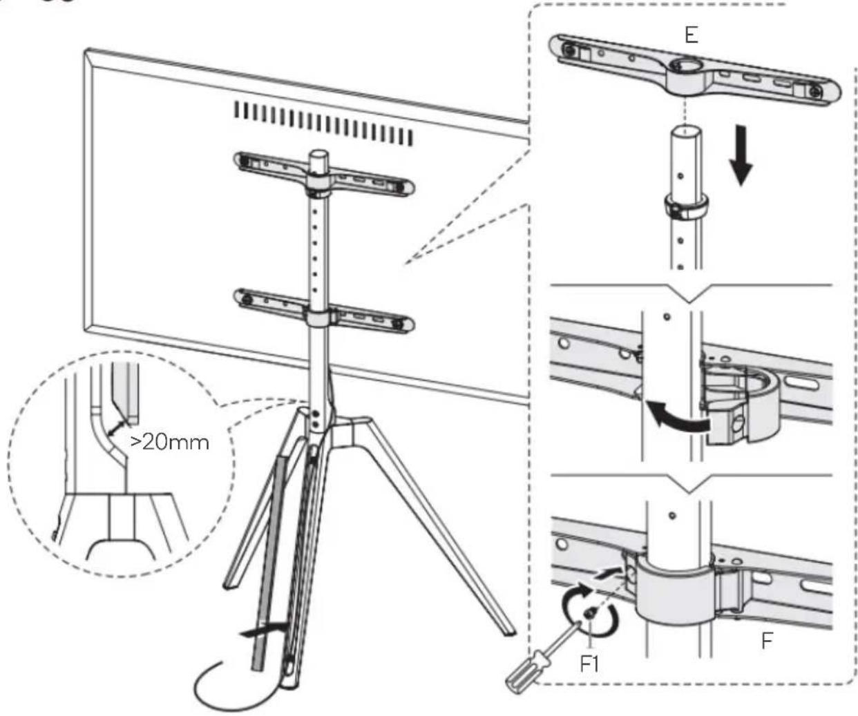
text_image
Technical diagram illustrating mechanical assembly steps with labeled components and dimensions, including a 20mm clearance and force application.Step 9:
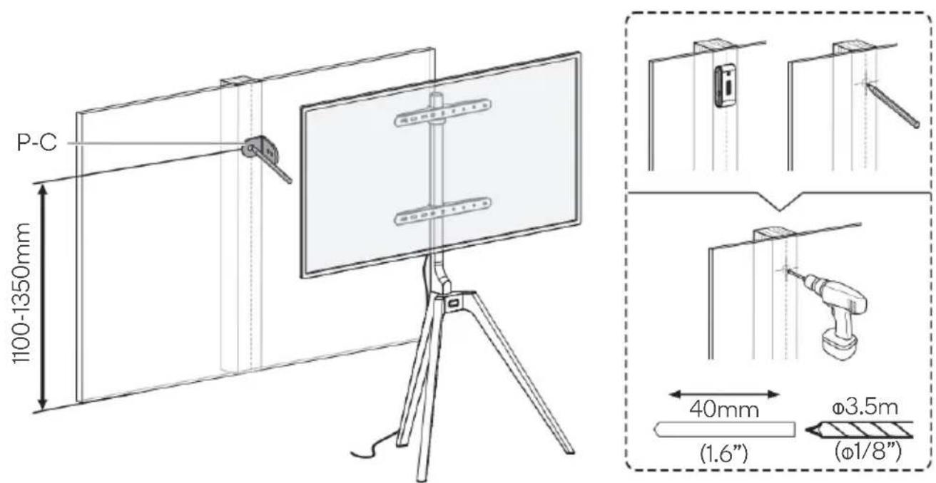
- To avoid the TV falling, it is highly recommended to install the anti-fall hardware.
- Mark the desired position for the anti-fall bracket (P-C).
- Drywall / plaster: Drill a pilot hole using a 3.5mm drill bit and drill.
- Masonry / concrete: Drill a pilot hole using a 7mmmm drill bit and drill.
text_image
P-C 1100-1350mm 40mm (1.6") Ø3.5m (Ø1/8")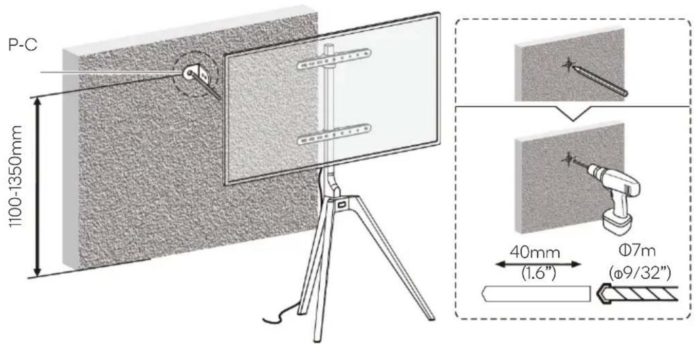
text_image
P-C 1100-1350mm 40mm (1.6") Ø7m (Ø9/32")Step 10:
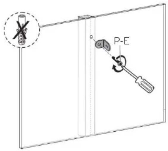
Drywall / plaster: Secure the anti-fall bracket (P-C) to the wall using the ST4.8x38 Screw (P-E).
Masonry / concrete: Secure the anti-fall bracket (P-C) to the wall using the wall anchor (P-F) and ST4.8x38 Screw (P-E).
text_image
P-E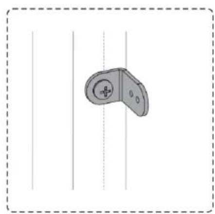
natural_image
Simple line drawing of a handheld device with a circular handle and central button, enclosed in a dashed border (no text or symbols)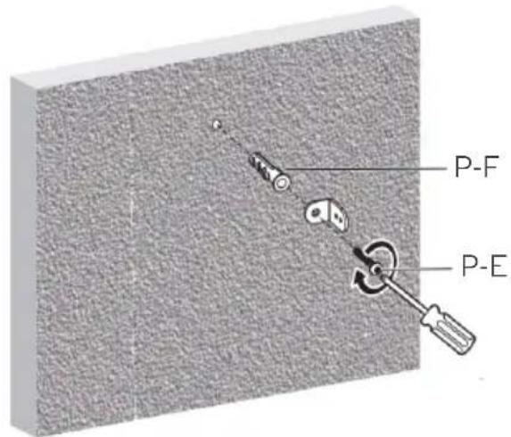
text_image
P-F P-E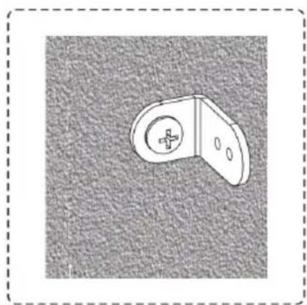
natural_image
Simple line drawing of a mechanical bracket or bracket with a circular hole and cross symbol, set against a textured gray background (no text or symbols)Step 11:
Using the anti-fall rope (P-A), cable clips (P-B) and rope screws (P-D) secure the TV to the Wall.
Note: Ensure there is enough tension on the rope so that the TV will not tip over.
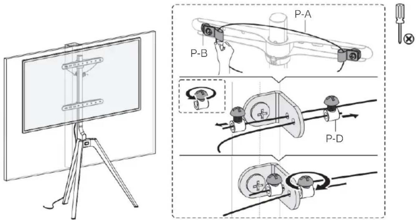
text_image
Technical diagram illustrating a cable or cable assembly process with labeled components P-A, P-B, and P-D, alongside a monitor view.NOTES
Need more information?
We hope that this user guide has given you the assistance needed for a simple set-up.
For the most up-to-date guide for your product, as well as any additional assistance you may require, head online to help.kogan.com
kogan.com