SuperServer SYS-211GT-HNTR - Server Supermicro - Free user manual and instructions
Find the device manual for free SuperServer SYS-211GT-HNTR Supermicro in PDF.

User questions about SuperServer SYS-211GT-HNTR Supermicro
0 question about this device. Answer the ones you know or ask your own.
Ask a new question about this device
Download the instructions for your Server in PDF format for free! Find your manual SuperServer SYS-211GT-HNTR - Supermicro and take your electronic device back in hand. On this page are published all the documents necessary for the use of your device. SuperServer SYS-211GT-HNTR by Supermicro.
USER MANUAL SuperServer SYS-211GT-HNTR Supermicro
natural_image
Front view of a rack-mounted server with multiple drive bays and orange-labeled ports (no visible text or labels)The information in this User's Manual has been carefully reviewed and is believed to be accurate. The vendor assumes no responsibility for any inaccuracies that may be contained in this document, and makes no commitment to update or to keep current the information in this manual, or to notify any person or organization of the updates. Please Note: For the most up-to-date version of this manual, please see our website at www.supermicro.com.
Super Micro Computer, Inc. ("Supermicro") reserves the right to make changes to the product described in this manual at any time and without notice. This product, including software and documentation, is the property of Supermicro and/or its licensors, and is supplied only under a license. Any use or reproduction of this product is not allowed, except as expressly permitted by the terms of said license.
IN NO EVENT WILL Super Micro Computer, Inc. BE LIABLE FOR DIRECT, INDIRECT, SPECIAL, INCIDENTAL, SPECULATIVE OR CONSEQUENTIAL DAMAGES ARISING FROM THE USE OR INABILITY TO USE THIS PRODUCT OR DOCUMENTATION, EVEN IF ADVISED OF THE POSSIBILITY OF SUCH DAMAGES. IN PARTICULAR, SUPER MICRO COMPUTER, INC. SHALL NOT HAVE LIABILITY FOR ANY HARDWARE, SOFTWARE, OR DATA STORED OR USED WITH THE PRODUCT, INCLUDING THE COSTS OF REPAIRING, REPLACING, INTEGRATING, INSTALLING OR RECOVERING SUCH HARDWARE, SOFTWARE, OR DATA.
Any disputes arising between manufacturer and customer shall be governed by the laws of Santa Clara County in the State of California, USA. The State of California, County of Santa Clara shall be the exclusive venue for the resolution of any such disputes. Supermicro's total liability for all claims will not exceed the price paid for the hardware product.
FCC Statement: This equipment has been tested and found to comply with the limits for a Class A or Class B digital device pursuant to Part 15 of the FCC Rules. These limits are designed to provide reasonable protection against harmful interference when the equipment is operated in industrial environment for Class A device or in residential environment for Class B device. This equipment generates, uses, and can radiate radio frequency energy and, if not installed and used in accordance with the manufacturer's instruction manual, may cause harmful interference with radio communications. Operation of this equipment in a residential area is likely to cause harmful interference, in which case you will be required to correct the interference at your own expense.
California Best Management Practices Regulations for Perchlorate Materials: This Perchlorate warning applies only to products containing CR (Manganese Dioxide) Lithium coin cells. "Perchlorate Material-special handling may apply. See www.dtsc.ca.gov/hazardouswaste/perchlorate".

WARNING: This product can expose you to chemicals including lead, known to the State of California to cause cancer and birth defects or other reproductive harm. For more information, go to www.P65Warnings.ca.gov.
The products sold by Supermicro are not intended for and will not be used in life support systems, medical equipment, nuclear facilities or systems, aircraft, aircraft devices, aircraft/emergency communication devices or other critical systems whose failure to perform be reasonably expected to result in significant injury or loss of life or catastrophic property damage. Accordingly, Supermicro disclaims any and all liability, and should buyer use or sell such products for use in such ultra-hazardous applications, it does so entirely at its own risk. Furthermore, buyer agrees to fully indemnify, defend and hold Supermicro harmless for and against any and all claims, demands, actions, litigation, and proceedings of any kind arising out of or related to such ultra-hazardous use or sale.
Manual Revision 1.0
Release Date: December 07, 2023
Unless you request and receive written permission from Super Micro Computer, Inc., you may not copy any part of this document. Information in this document is subject to change without notice. Other products and companies referred to herein are trademarks or registered trademarks of their respective companies or mark holders.
Copyright © 2023 by Super Micro Computer, Inc.
All rights reserved.
Printed in the United States of America
Preface
About this Manual
This manual is written for professional system integrators and PC technicians. It provides information for the installation and use of the A+ Server. Installation and maintenance should be performed by certified service technicians only.
Please refer to the SYS-211GT-HNTR/HNC8R server specifications page on our website for updates on supported memory, processors and operating systems (http://www.supermicro.com).
Notes
For your system to work properly, please follow the links below to download all necessary drivers/utilities and the user's manual for your server.
- Supermicro product manuals: http://www.supermicro.com/support/manuals/
- Product drivers and utilities: https://www.supermicro.com/wdl
- Product safety info: http://www.supermicro.com/about/policies/safety_information.cfm
If you have any questions, please contact our support team at:
support@supermicro.com
This manual may be periodically updated without notice. Please check the Supermicro website for possible updates to the manual revision level.
Secure Data Deletion
A secure data deletion tool designed to fully erase all data from storage devices can be found on our website: https://www.supermicro.com/about/policies/disclaimer.cfm?url=/wdl/utility/Lot9_Secure_Data_Deletion_Utility/
Warnings
Special attention should be given to the following symbols used in this manual.

Warning! Indicates important information given to prevent equipment/property damage or personal injury.
Warning! Indicates high voltage may be encountered when performing a procedure.
Contents
Contacting Supermicro....8
Chapter 1 Introduction
1.1 Overview....9
1.2 System Features ....10
System: Front View....10
Control Panel 11
System: Rear View....12
1.3 Motherboard Layout....13
Quick Reference Table....14
Block Diagram....15
Chapter 2 Server Installation
2.1 Overview....16
2.2 Preparing for Setup....16
Choosing a Setup Location....16
Rack Precautions....16
Server Precautions....17
Rack Mounting Considerations ....17
Ambient Operating Temperature....17
Airflow....17
Mechanical Loading....17
Circuit Overloading....18
Reliable Ground....18
2.3 Installing the Rails....19
Identifying the Rails....19
Adjusting the Rail Length ....19
Installing the Rails on a Rack....20
Chassis Installation 21
Chapter 3 Maintenance and Component Installation
3.1 Removing Power....22
3.2 Accessing the System....22
Removing a Computing Node Drawer....22
Installing and Removing the Node Drawers ....23
Removing the Chassis Cover ....24
3.3 Static-Sensitive Devices....25
Precautions ....25
Unpacking 25
3.4 Processor and Heatsink Installation....26
The 4th Generation Intel Xeon Scalable Processor ....26
Overview of the Processor Carrier Assembly 27
Overview of the CPU Socket....27
Overview of the Processor Heatsink Module....28
Creating the Processor Carrier Assembly....29
Assembling the Processor Heatsink Module 30
Preparing the CPU Socket for Installation....31
Installing the Processor Heatsink Module....32
Removing the Processor Heatsink Module....33
3.5 Memory....34
Memory Support....34
General Guidelines for Optimizing Memory Performance....36
DIMM Installation ....37
DIMM Removal ....37
Motherboard Battery ....38
3.6 Chassis Components ....39
Storage Drives 39
Drive Carrier Indicators ....39
Drive Configuration ....40
Removing/Installing Drives 41
Hot-Swap for NVMe Drives....43
Checking the Temperature of an NVMe Drive 44
AIOM Card 44
I/O Card Module....45
3.7 System Cooling....46
Fans 46
Installing the Air Shroud....47
3.8 Power Supply 48
3.9 Cable Routing Diagram....49
6x NVMe + 2x AIOM....49
3.9 BMC Reset....50
Chapter 4 Motherboard Connections
4.1 Power Connections ....51
4.2 Headers and Connectors ....51
4.3 Jumper Settings ....54
How Jumpers Work....54
4.4 LED Indicators....56
Chapter 5 Software
5.1 Microsoft Windows OS Installation....57
5.2 Driver Installation....59
5.3 SuperDoctor ^® 5....60
5.4 IPMI....61
BMC ADMIN User Password ....61
Chapter 6 Optional Components
6.1 Optional Parts List....62
6.2 Intel Virtual RAID on CPU (VROC)....63
Requirements and Restrictions....63
Supported SSDs and Operating Systems 63
Additional Information ....64
Hardware Key 64
Enabling NVMe RAID....65
Status Indications....68
Hot Swap Drives 68
Hot-unplug ....68
Hot-plug 68
Chapter 7 Troubleshooting and Support
7.1 Information Resources....69
Website 69
Direct Links for the SYS-211GT-HNTR/HNC8R System....69
Direct Links for General Support and Information ....69
7.2 Baseboard Management Controller Interface....70
7.3 Troubleshooting Procedures .....71
No Power 71
No Video 72
System Boot Failure 72
Memory Errors 72
Losing the System's Setup Configuration....72
When the System Becomes Unstable....72
7.4 Crash Dump Using BMC....74
7.5 UEFI BIOS Recovery ....75
Overview ....75
Recovering the UEFI BIOS Image....75
Recovering the Main BIOS Block with a USB Device....75
7.6 CMOS Clear....80
7.7 Where to Get Replacement Components....81
7.8 Reporting an Issue....81
Technical Support Procedures....81
Returning Merchandise for Service....81
Vendor Support Filing System 82
7.9 Feedback....82
7.10 Contacting Supermicro....83
Appendix A Standardized Warning Statements for AC Systems
Appendix B System Specifications
Contacting Supermicro
Headquarters
Address: Super Micro Computer, Inc.
980 Rock Ave.
San Jose, CA 95131 U.S.A.
Tel: +1 (408) 503-8000
Fax: +1 (408) 503-8008
Email: marketing@supermicro.com (General Information)
Sales-USA@supermicro.com (Sales Inquiries)
Government_Sales-USA@supermicro.com (Gov. Sales Inquiries)
support@supermicro.com (Technical Support)
RMA@supermicro.com (RMA Support)
Webmaster@supermicro.com (Webmaster)
Website: www.supermicro.com
Europe
Address: Super Micro Computer B.V.
's-Hertogenbosch, The Netherlands
Tel: +31 (0) 73-6400390
Fax: +31 (0) 73-6416525
Email: Sales_Europe@supermicro.com (Sales Inquiries)
Support_Europe@supermicro.com (Technical Support)
RMA_Europe@supermicro.com (RMA Support)
Website: www.supermicro.nl
Asia-Pacific
Address: Super Micro Computer, Inc.
3F, No. 150, Jian 1st Rd.
Zhonghe Dist., New Taipei City 235
Taiwan (R.O.C)
Tel: +886-(2) 8226-3990
Fax: +886-(2) 8226-3992
Email: Sales-Asia@supermicro.com.tw (Sales Inquiries)
Support@supermicro.com.tw (Technical Support)
RMA@supermicro.com.tw (RMA Support)
Website: www.supermicro.com.tw
Chapter 1
Introduction
1.1 Overview
This chapter provides a brief outline of the functions and features of the SuperServer SYS-211GT-HNTR/HNC8R. This is a GrandTwin™ system based on the X13SET-G/GC motherboard and the CSE-GT214BC-R2K21BP chassis.
The following provides an overview of the specifications and capabilities.
| System Overview | |
| Motherboard | SYS-211GT-HNTR: X13SET-GSYS-211GT-HNC8R: X13SET-GC |
| Chassis | CSE-GT214BC-R2K21BP |
| Processor | 4th Generation Intel Xeon Scalable Processor in a Socket E (LGA 4677) |
| Memory | Up to 4 TB of ECC RDIMM and RDIMM 3DS DDR5 memory with speeds of up to 4800 MT/s |
| Drive Support | SYS-211GT-HNTR: Twenty-four 2.5" hot-swap drive bays for NVMe or SATA drivesSYS-211GT-HNC8R: Twenty-four 2.5" hot-swap drive bays for NVMe/SAS/SATA drives |
| Expansion Slots | Two PCIe 5.0 x16 slots (per node) |
| I/O Ports | Each GrandTwin I/O module integrates a network solution and the I/O ports, including:Two USB 3.0 portsOne VGA portOne dedicated BMC LAN port |
| System Cooling | Two 8-cm mid chassis fans per system, one CPU air shroud per node, one CPU heatsink (per node) |
| Power | Two redundant power supply modules2200 W (Titanium Level) |
| Form Factor | 2U rackmount, (WxHxD) 17.67 x 3.46 x 28" (449 x 88 x 711.2 mm) |
Notes: A Quick Reference Guide can be found on the product page of the Supermicro website. The following safety models associated with the SYS-211GT-HNTR/HNC8R have been certified as compliant with UL or CSA: GT214BR-4N, GT214BR-R22X13.
1.2 System Features
System: Front View
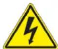
The CSE-GT214BC is a 2U chassis that supports four hot-plug nodes. Refer to Appendix B for additional specifications. The chassis front offers access to the storage drives, a control panel for each node, four pullout service tags, and two thumbscrews.
text_image
Control Panels for Node A (bottom) and Node B (top) Control Panels for Node C (bottom) and Node D (top) B1 B3 B5 D1 D3 D5 B0 B2 B4 D0 D2 A1 A3 A5 C1 C3 C5 A0 A2 Node A Drive Bays Node C Drive Bays Node B Drive Bays Node D Drive Bays Thumbscrew Node Handle ThumbscrewFigure 1-1. System Front View
| Front Chassis Features | |
| Feature Description | |
| Control Panel | Four control panels with labels located as follows: node A bottom left, node B top left, node C bottom right, and node D top right. |
| Service Tag Pull-out service tags with BMC password labels for each node. | |
| Drive Bays 24 hot-swap drive bays (six per node) | |
| Node Handles Handle supporting node tray removal | |
| Thumbscrews Two thumbscrews to secure the server onto the rack | |
Control Panel
Power switches and status LEDs are located on the control panel on the front of the chassis.

text_image
NIC LED Information LED Node Label Power Button i BMC Button/UID LED Node B SUPERMETHFigure 1-2. Control Panel (per node)
| Control Panel Features | |
| Feature Description | |
| Power Button | The main power switch applies or removes primary power from the power supply to the server but maintains standby power. |
| NIC LED Indicates network activity on the LAN when flashing. | |
| Information LED Universal information LED (see table below for details). | |
| BMC Button/UID LED (Node B) | The BMC reset button resets the BMC firmware when pressed. The unit identification (UID) button turns on or off the blue light function of the Information LED and a blue LED on the rear of the chassis. These are used to locate the server in large racks and server banks. |
| Node Label (Node B) | Label with the name of the node that is connected to the control panel. Labels for nodes A and C are above their control panel. Labels for nodes B and D are below their control panel. |
| Information LED | |
| Color, Status Description | |
| Red, solid An overheat condition has occurred. | |
| Red, blinking at 1 Hz Fan failure, check for an inoperative fan. | |
| Red, blinking at 0.25 Hz Power failure, check for a non-operational power supply | |
| Red, solid, with Power LED blinking green Fault detected | |
| Blue and red, blinking at 10 Hz Recovery mode | |
| Blue, solid | UID has been activated locally to locate the server in a rack environment. |
| Blue, blinking at 1 Hz | UID has been activated using the BMC to locate the server in a rack environment. |
| Blue, blinking at 2 Hz BMC is resetting | |
| Blue, blinking at 4 Hz BMC is setting factory defaults | |
| Blue, blinking at 10 Hz with Power LED blinking green | BMC/BIOS firmware is updating |
System: Rear View
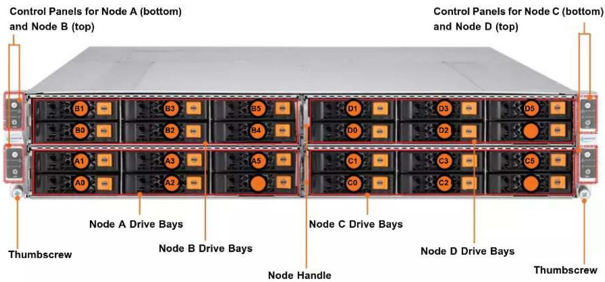
The illustration below shows the features on the rear of the chassis.
text_image
BMC LAN VGA Switch D2 D1 C2 C1 PWS2 Locking Clip Locking Lever USB VGA PWS1 Locking Clip Locking Lever USB VGA BMC LAN VGA Switch A2 A1Figure 1-3. System Rear View
| Rear Chassis Features | |
| Feature Description | |
| Locking Clip/Lever Power supply locking mechanisms | |
| BMC LAN Dedicated BMC LAN port | |
| USB Two USB 3.0 ports (shared by upper and lower nodes) | |
| VGA VGA port (shared by upper and lower nodes) | |
| VGA Switch Toggles VGA output between upper and lower nodes. | |
| Power Supplies | Two 2200 W Titanium level redundant power supply modulesPWS2 on the left, and PWS1 on the right |
| through [5266] ≥ 5.0 x16 AIOM (OCP 3.0) expansion slots | |
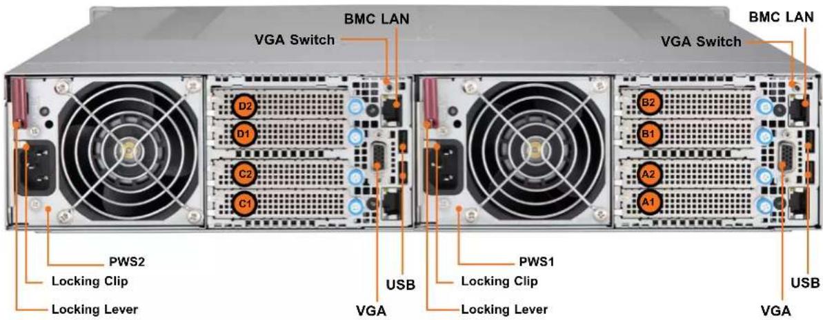
1.3 Motherboard Layout
Below is a layout of the X13SET-G/GC with jumper, connector and LED locations shown. See the table on the following page for descriptions. For detailed descriptions, pinout information and jumper settings, refer to Chapter 4.
text_image
JFIO1 JS2 JAIOM1SB1 JMD1 JMD2 JPW1 JS1 JAIOM1SB2 JNCSI1 MH10 MH12 JPMW2 JPMW1 LSEDS2 PCIE2B1 PCIE2A1 SAS3808 (-GC only) PCH C741 COM1 JTPM1 JIPMB1 LEDM1 PCIE1B1 PCIE1A1 JRK1 LED1 DIMME2 DIMME1 DIMMF2 DIMMF1 DIMMG2 DIMMG1 DIMMH2 DIMMH1 DIMMD1 DIMMD2 DIMMC1 DIMMC2 DIMMB1 DIMMB2 DIMMA1 DIMMA2 CPU JWD1 JI2C1 (JPCIE1A1) JI2C2 (JPCIE1B1) JPME2 JBT1 BT1 FAN1 JPWR1 J35 J40 BAR CODE/PMI CODE FCFigure 1-6. Motherboard Layout
Notes:
- Components not documented are for internal testing only.
- Use only the correct type of onboard CMOS battery as specified by the manufacturer. Do not install the onboard battery upside down to avoid possible explosion.
Quick Reference Table
Jumper Description Default Setting
| JBT1 CMOS Clear Open (Normal) |
| JI2C1, JI2C2 Backplane or Riser Card/AIOM Enable Pins 1-2 (RSC/AIOM) |
| JPME2 ME Manufacturing Mode Pins 1-2 (Normal) |
| JWD1 Watch Dog Timer Pins 1-2 (Reset) |
LED Description Status
| LED1 UID LED Solid Blue: Unit Identified | ||
| LEDM1 | BMC Heartbeat LED | Blinking Green: BMC Normal |
| LSEDS2 | SAS Heartbeat LED | Blinking Green: SAS Active |
| Connector | Description | |
| AIOM1SB1 | AIOM1 Sideband Signals Header | |
| AIOM1SB2 | AIOM2 Sideband Signals Header | |
| BT1 | Onboard Battery | |
| COM1 COM Header | ||
| JFIO | Grand Twin Front IPMI And Onboard NIC Module Connector | |
| FAN1 | CPU/System Fan Header (FAN1: CPU Fan) | |
| J35, J40 | Molex Impel Plus Connectors | |
| JIPMB1 | System Management Bus Header (for IPMI only) | |
| JMD1, JMD2 | M.2 Slots (PCIe3.0 x4 and SATA) | |
| JNCSI1 | NC-SI (Network Controller Sideband Interface) Connector | |
| JPMW1, JPMW2 | Power Connectors for PCIe or GPU | |
| JPCIE1A1 | PE0 0-7 PCIe Connector | |
| JPCIE1B1 | PE0 8-15 PCIe Connector | |
| JPCIE2A1 | PE1 0-7 PCIe Connector | |
| JPCIE2B1 | PE1 8-15 PCIe Connector | |
| JPW1 | Power Connector for Storage Backplane | |
| JPWR1 BPN-PDB-GT214 Connector for Power Supply | ||
| JRIO1 | Connector for Rear I/O Module | |
| JRK1 | Intel RAID Key Header | |
| JS1 | X13SET-G: SATA0-3, X13SET-GC: SAS0-3 | |
| JS2 | X13SET-G: SATA4-5, X13SET-GC: SAS4-5 | |
| JTPM1 | Trusted Platform Module/Port 80 Connector | |
| MH10, MH12 | M.2 Mounting Holes | |
Note: the only difference between the two motherboard models is the inclusion of a LSI3808 controller for onboard SAS ports on the X13SET-GC.
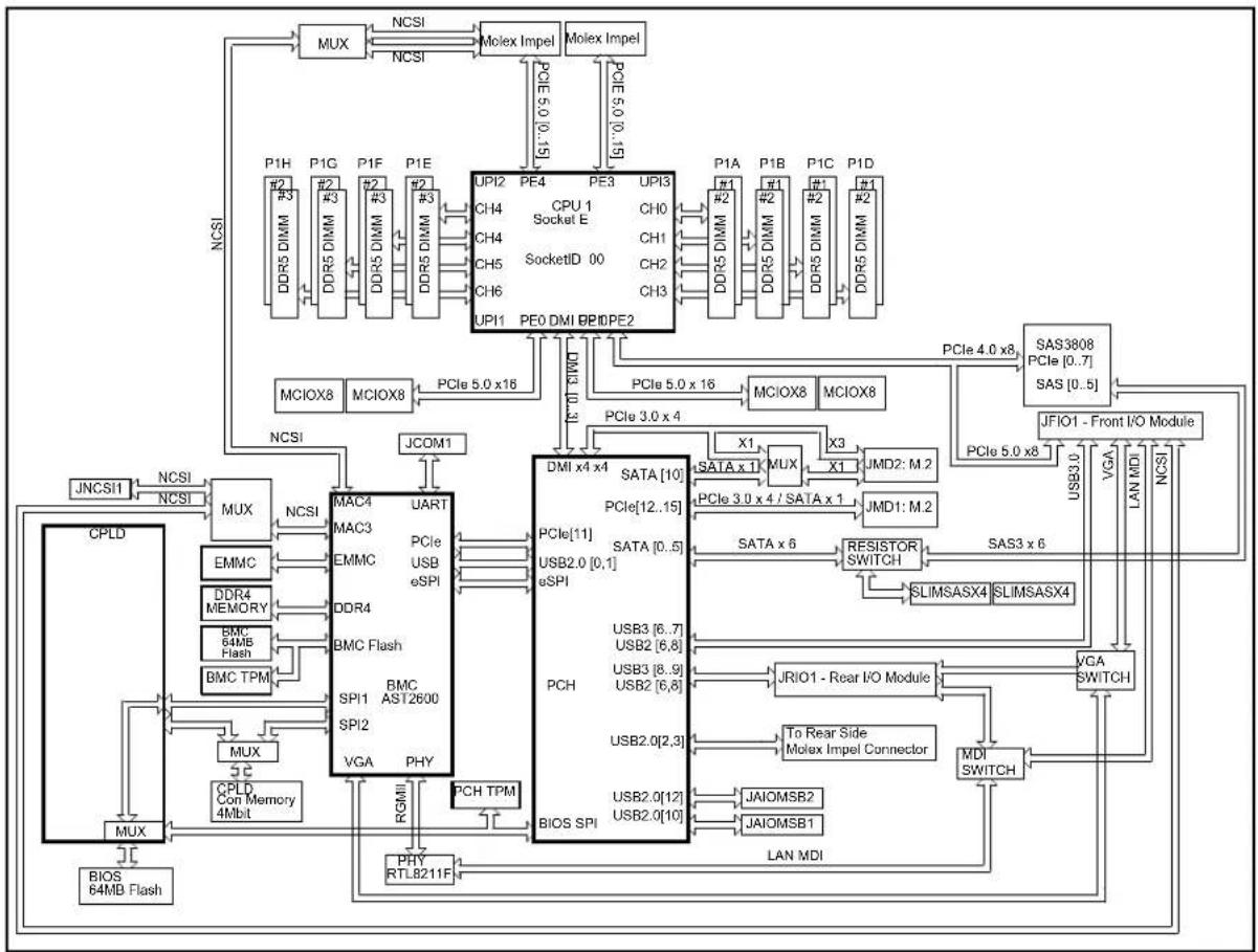
Block Diagram
flowchart
graph TD
    subgraph I/O Modules
        A["MUX"] -->|NCSI| B["Molex Impel"]
        B -->|NCSI| C["PCIe 5.0 x16"]
        C --> D["PCIe 3.0 x4"]
        D --> E["PCIe 5.0 x16"]
        E --> F["PCIe 4.0 x8"]
        F --> G["SAS3808 PCIe [0..7"] SAS["0..5"]]
        G --> H["PCIe 5.0 x8"]
        H --> I["UFIO1 - Front I/O Module"]
        I --> J["PCIe 5.0 x8"]
        J --> K["SIIMSASX4 SLIMSASX4"]
        K --> L["SAS3 x6"]
        L --> M["RESISTOR SWITCH"]
        M --> N["JRI01 - Rear I/O Module"]
        N --> O["MDI SWITCH"]
        O --> P["MDI SPI"]
        P --> Q["USB2.0[12"] USB2.0["10"]]
        Q --> R["USB2.0[2,3"]]
        R --> S["PCH TPM"]
        S --> T["BIOS SPI"]
        T --> U["PCle 11S SATA [0..5"] USB2.0["0,1"] eSPI]
        U --> V["PCIe[11"] SATA["0..5"] USB2.0["0,1"] eSPI]
        V --> W["PCIe[12..15"] SATA["0..5"] USB2.0["0,1"] eSPI]
        W --> X["PCIe 12..15"] SATA["0..5"] USB2.0["0,1"] eSPI
        X --> Y["SATA x6"]
        Y --> Z["SATA x6"]
        Z --> AA["SATA x6"]
        AA --> AB["SATA x6"]
    end

    subgraph Control Modules
        AC["CPLD"] --> AD["EMMC"]
        AD --> AE["DDR4 MEMORY"]
        AE --> AF["BMC 64MB Flash"]
        AF --> AG["BMC TPM"]
        AG --> AH["MUX"]
        AH --> AI["CPLD Con Memory 4Mbit"]
        AI --> AJ["MUX"]
        AJ --> AK["BIOS 64MB Flash"]

    subgraph I/O Modules
        AL["P1H"] --> AM["DDR5 DIMM"]
        AM --> AN["DDR5 DIMM"]
        AN --> AO["DDR5 DIMM"]
        AO --> AP["DDR5 DIMM"]
        AP --> AQ["DDR5 DIMM"]
        AQ --> AR["DDR5 DIMM"]
        AR --> AS["DDR5 DIMM"]
        AS --> AT["DDR5 DIMM"]
        AT --> AU["DDR5 DIMM"]
    end

    subgraph Control Modules
        AV["NCSI"] --> AW["PCIe 5.0 x16"]
        AW --> AX["PCIe 3.0 x4"]
        AX --> AY["PCIe 5.0 x16"]
        AY --> AZ["PCIe 4.0 x8"]
        AZ --> BA["PCIe 5.0 x8"]
    end

    subgraph Control Modules
        BB["NCSI"] --> BC["PCIe 5.0 x16"]
        BC --> BD["PCIe 4.0 x8"]
    end

    subgraph Control Modules
        BE["NCSI"] --> BF["NCSI"]
    end

    subgraph Control Modules
        BG["NCSI"] --> BH["NCSI"]
    end

    subgraph Control Modules
        BI["NCSI"] --> BJ["NCSI"]
    end

    subgraph Control Modules
        BK["NCSI"] --> BL["NCSI"]
    end

    subgraph Control Modules
        BM["NCSI"] --> BN["NCSI"]
    end

    subgraph Control Modules
        BO["NCSI"] --> BP["NCSI"]
    end

    subgraph Control Modules
        BQ["NCSI"] --> BR["NCSI"]
    end

    subgraph Control Modules
        BS["NCSI"] --> BT["NCSI"]
    end

    subgraph Control Modules
        BU["NCSI"] --> BV["NCSI"]
    end

    subgraph Control Modules
        BW["NCSI"] --> BX["NCSI"]
    end

    subgraph Control Modules
        BY["NCSI"] --> BZ["NCSI"]
    end

    subgraph Control Modules
        CA["NCSI"] --> CB["NCSI"]
    end

    subgraph Control Modules
        CC["NCSI"] --> CD["NCSI"]
    end

    subgraph Control Modules
        CE["NCSI"] --> CF["NCSI"]
    end

    subgraph Control Modules
        GD["NCSI"] --> DH["NCSI"]
    end

    subgraph Control Modules
        DI["NCSI"] --> DJ["NCSI"]
    end

    subgraph Control Modules
        DK["NCSI"] --> DL["NCSI"]
    end

    subgraph Control Modules
        DM["NCSI"] --> DE["NCSI"]
    end

    subgraph Control Modules
        DF["NCSI"] --> DG["NCSI"]
    end

    subgraph Control Modules
        DH["NCSI"] --> DI
    end
Figure 1-7. Chipset Block Diagram
Note: This is a general block diagram and may not exactly represent the features on your motherboard. See the previous pages for the actual specifications of your motherboard.
Chapter 2
Server Installation
2.1 Overview
This chapter provides advice and instructions for mounting your system in a server rack. If your system is not already fully integrated with processors, system memory etc., refer to Chapter 4 for details on installing those specific components.
Caution: Electrostatic Discharge (ESD) can damage electronic components. To prevent such damage to PCBs (printed circuit boards), it is important to use a grounded wrist strap, handle all PCBs by their edges and keep them in anti-static bags when not in use.
2.2 Preparing for Setup
The box in which the system was shipped should include the rackmount hardware needed to install it into the rack. Please read this section in its entirety before you begin the installation.
Choosing a Setup Location
- The system should be situated in a clean, dust-free area that is well ventilated. Avoid areas where heat, electrical noise and electromagnetic fields are generated.
- Leave enough clearance in front of the rack so that you can open the front door completely (approximately 25 inches) and approximately 30 inches of clearance in the back of the rack to allow sufficient space for airflow and access when servicing.
- This product should be installed only in a Restricted Access Location (dedicated equipment rooms, service closets, etc.).
- This product is not suitable for use with visual display workplace devices according to §2 of the German Ordinance for Work with Visual Display Units.
Rack Precautions
- Ensure that the leveling jacks on the bottom of the rack are extended to the floor so that the full weight of the rack rests on them.
-
In single rack installations, stabilizers should be attached to the rack. In multiple rack installations, the racks should be coupled together.
-
Always make sure the rack is stable before extending a server or other component from the rack.
- You should extend only one server or component at a time - extending two or more simultaneously may cause the rack to become unstable.
Server Precautions
- Review the electrical and general safety precautions in Appendix A.
- Determine the placement of each component in the rack before you install the rails.
- Install the heaviest server components at the bottom of the rack first and then work your way up.
- Use a regulating uninterruptible power supply (UPS) to protect the server from power surges and voltage spikes and to keep your system operating in case of a power failure.
- Allow any drives and power supply modules to cool before touching them.
- When not servicing, always keep the front door of the rack and all covers/panels on the servers closed to maintain proper cooling.
Rack Mounting Considerations
Ambient Operating Temperature
If installed in a closed or multi-unit rack assembly, the ambient operating temperature of the rack environment may be greater than the room's ambient temperature. Therefore, consideration should be given to installing the equipment in an environment compatible with the manufacturer's maximum rated ambient temperature (TMRA).
Airflow
Equipment should be mounted into a rack so that the amount of airflow required for safe operation is not compromised.
Mechanical Loading
Equipment should be mounted into a rack so that a hazardous condition does not arise due to uneven mechanical loading.
Circuit Overloading
Consideration should be given to the connection of the equipment to the power supply circuitry and the effect that any possible overloading of circuits might have on overcurrent protection and power supply wiring. Appropriate consideration of equipment nameplate ratings should be used when addressing this concern.
Reliable Ground
A reliable ground must be maintained at all times. To ensure this, the rack itself should be grounded. Particular attention should be given to power supply connections other than the direct connections to the branch circuit (i.e. the use of power strips, etc.).

To prevent bodily injury when mounting or servicing this unit in a rack, you must take special precautions to ensure that the system remains stable. The following guidelines are provided to ensure your safety:
- This unit should be mounted at the bottom of the rack if it is the only unit in the rack.
- When mounting this unit in a partially filled rack, load the rack from the bottom to the top with the heaviest component at the bottom of the rack.
- If the rack is provided with stabilizing devices, install the stabilizers before mounting or servicing the unit in the rack.
- Slide rail mounted equipment is not to be used as a shelf or a work space.
2.3 Installing the Rails
This section provides information on installing the chassis into a rack unit with the rails provided. There are a variety of rack units on the market, which may mean that the assembly procedure will differ slightly from the instructions provided. You should also refer to the installation instructions that came with the rack unit you are using.
Note: This rail will fit a rack between 28" and 33.5" deep.
Identifying the Rails
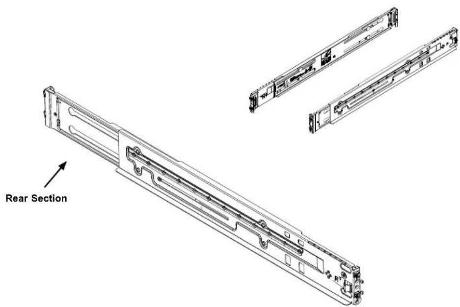
The package includes two rail assemblies. Each is specifically designed for the left or right side of the chassis, and so marked. Each rail consists of two sections: a front section which secures to the front post of the rack and a rear section which adjusts in length and secures to the rear post of the rack.
text_image
Rear SectionFigure 2-1. Rackmount Rail (Left & Right rail assembly shown)
Adjusting the Rail Length
Each rail assembly has a locking screw to adjust the length of the rail to fit the depth of your rack.
Installing the Rails on a Rack
- Loosen the adjusting screw to allow the rear section to slide in the front section.
- Push the small hooks on the front section of the rail into the holes on the front post of the rack and then down, until the spring-loaded pegs snap into the rack holes. Secure the rail to the rack with screws.
- Pull out the rear section of the outer rail, adjusting the length until it fits within the posts of the rack and align the small hooks with the appropriate holes on the rear post of the rack. Be sure the rail is level, then mount the rear section onto the rack. Secure the rail with screws.
- Tighten the adjusting screw.

natural_image
Technical line drawing of a mechanical assembly with vertical supports and mounting brackets (no text or symbols)Figure 2-2. Attaching the Rail Front to the Rack (Left rail shown)
Note: Figures are for illustrative purposes only. Always install servers into racks from the bottom up.
Chassis Installation
Slide the chassis into the rack so that the bottom of the chassis slides onto the bottom lip of the rails.
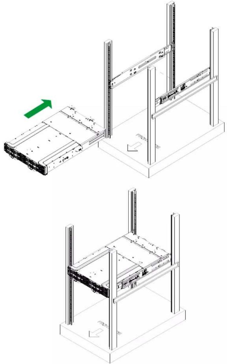
natural_image
Technical line drawings of server racks and storage units in three different configurations (no text or symbols)Figure 2-3. Sliding the Chassis into the Rack

Stability hazard. The rack stabilizing mechanism must be in place, or the rack must be bolted to the floor before you slide the unit out for servicing. Failure to stabilize the rack can cause the rack to tip over.
Note: Figures are for illustrative purposes only. Always install servers into racks from the bottom up.
Chapter 3
Maintenance and Component Installation
This chapter provides instructions on installing and replacing main system components. To prevent compatibility issues, only use components that match the specifications and/or part numbers given.
Installation or replacement of most components require that power first be removed from the system. Please follow the procedures given in each section.
3.1 Removing Power
Before performing some setup or maintenance tasks, use the following procedure to ensure that power has been removed from the system.
Removing Power from a Node
Use the operating system to power down the node.
Removing Power from the System
- Use the operating system to power down all nodes.
- Grasp the head of each power cord and gently pull it out of the back of the power supply.
- Disconnect the cords from the power strip or wall outlet.
3.2 Accessing the System
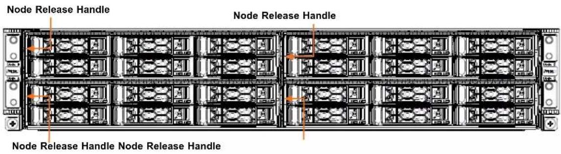
Removing a Computing Node Drawer
text_image
Node Release Handle Node Release Handle Node Release Handle Node Release HandleFigure 3-1. Removing a Node Tray
Installing and Removing the Node Drawers
The SYS-211GT-HNTR/HNC8R contains four individual motherboards in separate node drawers.
Warning: Except for short periods of time, do not operate the server without the cover in place, which helps maintain proper airflow and prevent overheating.
Removing Nodes from the Chassis
Each of the four individual nodes may be removed from the chassis without powering down the system.
- Use the operating system to power down the node and remove any cables attached to the node as described in Section 3.1.
- Push on the latch of the left handle to disengage the node tray.
- While pressing on the left latch, carefully pull the left node release handle out a small section.
- Grasp the node by the handles on both sides of the front, then pull the node forward and out of the chassis.
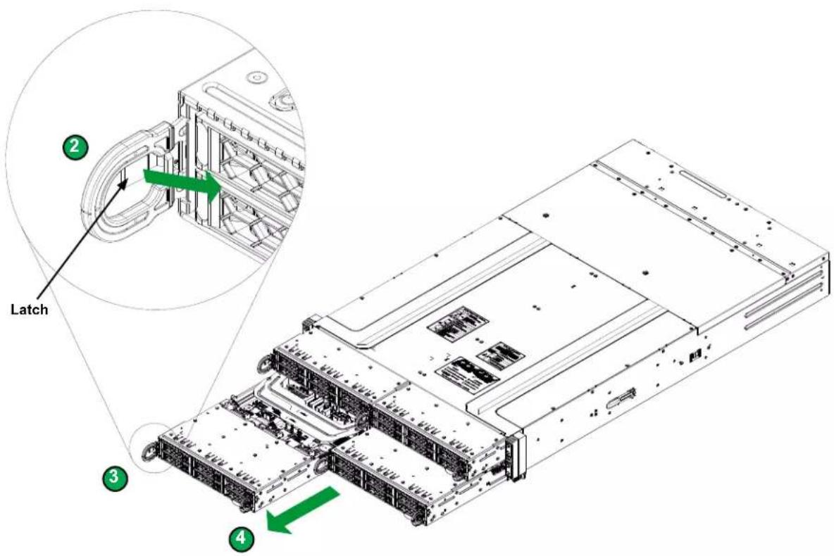
text_image
Latch ② ③ ④Figure 3-2. Removing a Node from the Chassis
Removing the Chassis Cover
You can access some chassis components, such as fans, by removing the cover.
Removing the Chassis Cover
- Remove the four screws securing the cover to the chassis.
- Slide the cover toward the rear of the chassis.
- Lift the top cover off of the chassis.
Caution: Except for short periods of time, do not operate the server without the cover in place. It provides proper airflow to prevent overheating.

natural_image
Technical line drawing of a server rack with multiple drive bays and mounting points (no text or labels)Figure 3-3. Removing the Chassis Cover
3.3 Static-Sensitive Devices
Electrostatic Discharge (ESD) can damage electronic components. To prevent damage to your motherboard, it is important to handle it very carefully. The following measures are generally sufficient to protect your equipment from ESD.
Precautions
- Use a grounded wrist strap designed to prevent static discharge.
- Touch a grounded metal object before removing the board from the antistatic bag.
- Handle the board by its edges only; do not touch its components, peripheral chips, memory modules or gold contacts.
- When handling chips or modules, avoid touching their pins.
- Put the motherboard and peripherals back into their antistatic bags when not in use.
- For grounding purposes, make sure that your chassis provides excellent conductivity between the power supply, the case, the mounting fasteners and the motherboard.
- Use only the correct type of CMOS onboard battery as specified by the manufacturer. Do not install the CMOS battery upside down, which may result in a possible explosion.
Unpacking
The motherboard is shipped in antistatic packaging to avoid static damage. When unpacking the motherboard, make sure that the person handling it is static protected.
3.4 Processor and Heatsink Installation
The processor (CPU) and processor carrier should be assembled together first to form the processor carrier assembly. This will be attached to the heatsink to form the processor heatsink module (PHM) before being installed onto the CPU socket.
Notes:
- Use ESD protection.
- Shut down the system and then unplug the AC power cord from all power supplies.
- Check that the plastic protective cover is on the CPU socket and none of the socket pins are bent. If they are, contact your retailer.
- When handling the processor, avoid touching or placing direct pressure on the LGA lands (gold contacts). Improper installation or socket misalignment can cause serious damage to the processor or socket, which may require manufacturer repairs.
- Thermal grease is pre-applied on a new heatsink. No additional thermal grease is needed.
• Refer to the Supermicro website for updates on processor support. - All graphics in this manual are for illustration purposes only. Your components may look different.
- Please order the CPU carrier with the CPU heatsink.
| CPU carrier for 4th Generation Intel Xeon Scalable Processors (XCC) | SKT-1333L-0000-FXC |
| CPU carrier for 4th Generation Intel Xeon Scalable Processors (MCC) | SKT-1424L-001B-FXC |
| CPU carrier for 4th Generation Intel Xeon Scalable Processors (HBM) | SKT-1425H-001C-FXC |
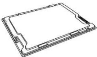
The 4th Generation Intel Xeon Scalable Processor
natural_image
Line drawing of a rectangular electronic device with mounting brackets and a central screen (no text or symbols)Intel Xeon Processor
Overview of the Processor Carrier Assembly
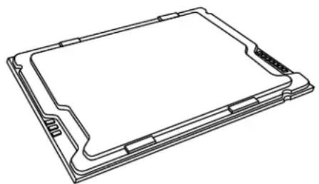
The processor carrier assembly contains the Intel Xeon processor and a processor carrier.
- Intel Xeon Processor
natural_image
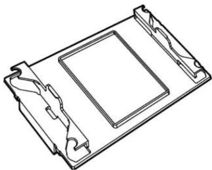
Line drawing of a rectangular electronic device with mounting holes and a flat top (no text or symbols)- Processor Carrier

natural_image
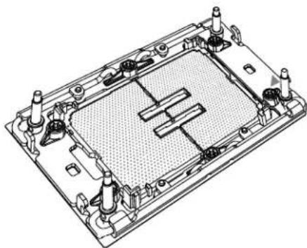
Technical line drawing of a mechanical housing or enclosure with internal components (no text or symbols)Overview of the CPU Socket
The CPU socket is protected by a plastic protective cover.
- Plastic Protective Cover
natural_image
Technical line drawing of a rectangular electronic component with mounting brackets and a central square (no text or symbols)- CPU Socket
natural_image
Technical line drawing of a mechanical housing or enclosure with internal components and mounting holes (no text or symbols)Overview of the Processor Heatsink Module
The Processor Heatsink Module (PHM) contains a heatsink, a processor carrier, and the Intel Xeon processor.
- Heatsink with Thermal Grease

natural_image
Isometric technical diagram of a heat exchanger or cooling unit with cooling elements and a central cooling element (no text or labels)- Processor Carrier
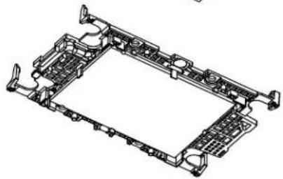
natural_image
Technical line drawing of a mechanical component with no visible text or symbols- Intel Xeon Processor

natural_image
Illustration of a rectangular device with a grid pattern and internal symbols (no text or labels)Processor Heatsink Module (PHM)

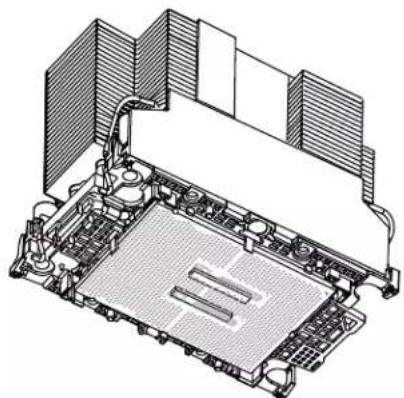
natural_image
Technical illustration of a computer motherboard with cooling fans and heatsink (no text or symbols)Bottom View
Creating the Processor Carrier Assembly
To install a processor into the processor carrier, follow the steps below:
- Before installation, make sure the lever on the processor carrier is pressed down as shown below.
- Hold the processor with the LGA lands (gold contacts) facing up. Locate the small, gold triangle in the corner of the processor and the corresponding hollowed triangle on the processor carrier. These triangles indicate pin 1. See the images below.
- Use the triangles as a guide to carefully align and place one end of the processor into the latch marked A, and place the other end of processor into the latch marked B as shown below.
- Examine all corners to ensure that the processor is firmly attached to the carrier.

text_image
Pin 1 Make sure the lever is pressed down before installing the processor. A B Processor Carrier AssemblyAssembling the Processor Heatsink Module
After creating the processor carrier assembly for the processor, mount it onto the heatsink to create the processor heatsink module (PHM):
- Note the label on top of the heatsink, which marks the airflow direction. Turn the heatsink over and orient the heatsink so the airflow arrow is pointing towards the triangle on the processor.
- If this is a new heatsink, the thermal grease has been pre-applied. Otherwise, apply the proper amount of thermal grease.
- Hold the processor carrier assembly so the processor's gold contacts are facing up, then align the holes of the processor carrier assembly with the holes on the heatsink. Press the processor carrier assembly down until it snaps into place. The plastic clips of the processor carrier assembly will lock at the four corners.
- Examine all corners to ensure that the plastic clips on the processor carrier assembly are firmly attached to the heatsink.
Processor Carrier Assembly (Upside Down)

text_image
Triangle on the CPU Triangle on the processor carrier Thermal grease Airflow direction (Refer to the airflow arrow on the heatsink label to orient the heatsink) Check each corner to ensure that the processor carrier is firmly attached to the heatsink.Preparing the CPU Socket for Installation
This motherboard comes with a plastic protective cover installed on the CPU socket. Remove it from the socket to install the Processor Heatsink Module (PHM). Gently pull up one corner of the plastic protective cover to remove it.
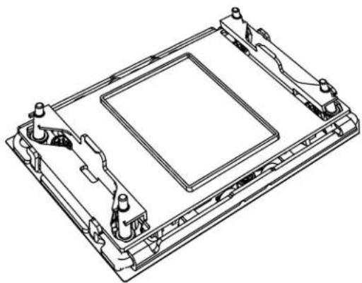
natural_image
Technical line drawing of a mechanical component with mounting brackets and central square (no text or symbols)CPU Socket with Plastic Protective Cover
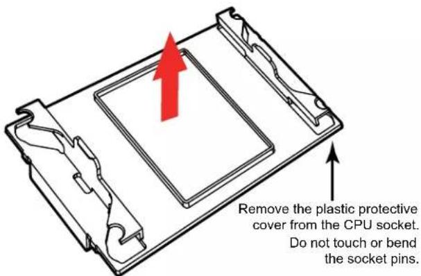
text_image
Remove the plastic protective cover from the CPU socket. Do not touch or bend the socket pins.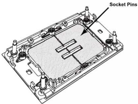
text_image
Socket PinsInstalling the Processor Heatsink Module
After assembling the Processor Heatsink Module (PHM), install it onto the CPU socket:
- Align pin 1 of the PHM with the printed triangle on the CPU socket. See the left image below.
- Make sure all four holes of the heatsink are aligned with the socket, then gently place the heatsink on top of the CPU socket.
- Press all four rotating wires outwards and make sure that the heatsink is securely latched into the CPU socket.
- With a T30 Torx-bit screwdriver, gradually tighten the four screws to ensure even pressure. You can start with any screw, but make sure to tighten the screws in a diagonal pattern. To avoid damaging the processor or socket, do not use a force greater than 12 lbf-in when tightening the screws.
- Examine all corners to ensure that the PHM is firmly attached to the socket.

text_image
Airflow direction Pin 1 Printed Triangle Mounte the Processor Heatsink Module onto the CPU socket (on the motherboard). T30 Torx Screwdriver Use a torque of 12 lbf-in Press the rotating wires outwards to latch the PHM and then tighten the four screws.Removing the Processor Heatsink Module
Before removing the processor heatsink module (PHM) from the motherboard, shut down the system and then unplug the AC power cord from all power supplies.
Then follow the steps below:
- Use a T30 Torx-bit screwdriver to loosen the four screws. You can start with any screw, but make sure to loosen the screws in a diagonal pattern.
- Press the four rotating wires inwards to unlatch the PHM from the socket.
- Gently lift the PHM upwards to remove it from the socket.
- To remove the CPU, move the lever to its unlocked position and gently remove the CPU.

natural_image
Technical diagram of a mechanical device with red arrows indicating directional movement or assembly (no text or symbols present)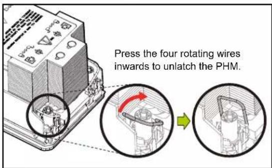
text_image
Press the four rotating wires inwards to unlatch the PHM.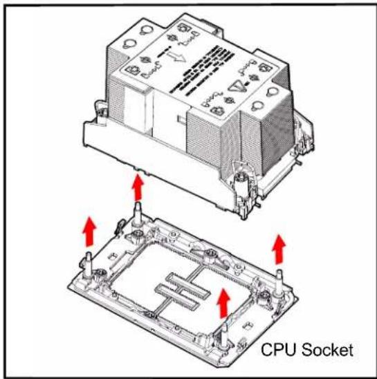
text_image
CPU Socket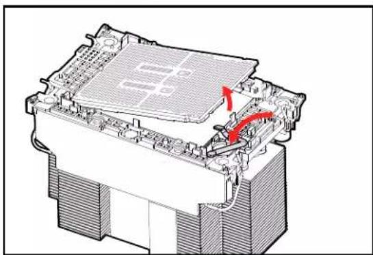
natural_image
Technical diagram of a computer processor internal structure with highlighted components and red directional arrows indicating motion (no text or symbols)3.5 Memory
Note: Check the Supermicro website for recommended memory modules.
Important: Exercise extreme care when installing or removing DIMM modules to prevent any possible damage.
Memory Support
The X13SET-G/GC supports up to 4 TB of ECC RDIMM and RDIMM 3DS DDR5 memory with speeds of up to 4800 MT/s (DDR5-4400MT/s when fully populated) in 16 memory slots. Refer to the table below for the recommended DIMM population order.
| 1 CPU, 16 DIMM Slots | |
| Number of DIMMs Memory | Population Sequence |
| 1 | DIMMA1 |
| DIMME1 | |
| DIMMB1 | |
| DIMMF1 | |
| 2 | DIMMA1 / DIMMG1 |
| DIMMC1 / DIMME1 | |
| 4 DIMMA1 / DIMMG1 / DIMMC1 / DIMME1 | |
| 6 | DIMMA1 / DIMMG1 / DIMMC1 / DIMME1 / DIMMD1 / DIMMF1 |
| DIMMA1 / DIMMG1 / DIMMC1 / DIMME1 / DIMMB1 / DIMMH1 | |
| DIMMC1 / DIMME1 / DIMMB1 / DIMMH1 / DIMMD1 / DIMMF1 | |
| DIMMA1 / DIMMG1 / DIMMB1 / DIMMH1 / DIMMD1 / DIMMF1 | |
| 8 DIMMA1 / DIMMG1 / DIMMB1 / DIMMH1 / DIMMD1 / DIMMF1 / DIMMC1 /DIMME1 | |
| 12 | DIMMA1 / DIMMA2 / DIMMB1 / DIMMC1 / DIMMC2 / DIMMD1 / DIMME1 / DIMME2 / DIMMF1 / DIMMG1 / DIMMG2 / DIMMH1 |
| DIMMA1 / DIMMB1 / DIMMB2 / DIMMC1 / DIMMD1 / DIMMD2 / DIMME1 / DIMMF1 / DIMMF2 / DIMMG1 / DIMMH1 / DIMMH2 | |
| 16 | DIMMA1 / DIMMA2 / DIMMB1 / DIMMB2 / DIMMC1 / DIMMC2 / DIMMD1 / DIMMD2 / DIMME1 / DIMME2 / DIMMF1 / DIMMF2 / DIMMG1 / DIMMG2 / DIMMH1 / DIMMH2 |
| 1 HBM CPU, 16 DIMM Slots | |
| Number of DIMMs Memory | Population Sequence |
| 0 | |
| 1 | DIMMA1DIMME1 |
| 2 | DIMMA1 / DIMMG1DIMMC1 / DIMME1 |
| 4 DIMMA1 / DIMMG1 | DIMMC1 / DIMME1 |
| 8 DIMMA1 / DIMMG1 | DIMMC1 / DIMME1 / DIMMD1 / DIMMF1 / DIMMB1 / DIMMH1 |
| 16 | DIMMA1 / DIMMA2 / DIMMB1 / DIMMB2 / DIMMC1 / DIMMC2 / DIMMD1 / DIMMD2 / DIMME1 / DIMME2 / DIMMF1 / DIMMF2 / DIMMG1 / DIMMG2 / DIMMH1 / DIMMH2 |
| Compatible and Incompatible DIMM Types | |
| DIMM Type RDIMM RDIMM 3DS 9x4 RDIMM | |
| RDIMM Compatible Incompatible Incompatible | |
| RDIMM 3DS Incompatible Compatible Incompatible | |
| 9x4 RDIMM Incompatible Incompatible Compatible | |
| Type | Ranks Per DIMM and Data Width | DIMM Capacity (GB) | Speed (MT/s); Voltage (V); Slot Per Channel (SPC) and DIMM Per Channel (DPC)*Data below assumes 2 SPC unless otherwise noted. | |
| 1DPC 2DPC | ||||
| Memory Density: 16 Gb | 1.1V 1.1V | |||
| RDIMM | SRx8 (RC D) 16 GB | 4800 4400 | ||
| SRx4 (RC C) 32 GB | ||||
| SRx5 (RC F) 9x4 32 GB | ||||
| DRx8 (RC E) 32 GB | ||||
| DRx4 (RC A) 64 GB | ||||
| DRx4 (RC B) 9x4 64 GB | ||||
| RDIMM 3DS (4R/8R) x4 (RC A) | 2H-128 GB4H 256 GB | 4800 4400 | ||
General Guidelines for Optimizing Memory Performance
- It is recommended to use DDR5 memory of the same type, size, and speed.
- Mixed DIMM speeds can be installed. However, all DIMMs will run at the speed of the slowest DIMM.
• To achieve the best memory performance, a balanced memory population is recommended. - The motherboard will not support an odd number of modules (except for a single DIMM module necessary for board operation. To achieve the best memory performance, a balanced (even number) memory population is recommended.

text_image
SAS3808 (-GC only) PCH C741 BMC Controller SUPER X13SET-G DESHRED IN USA CPU CPLD SAS CODE BAR CODE/PMI CODE DIMMH1 DIMMH2 DIMMG1 DIMMG2 DIMMF1 DIMMF2 DIMME1 DIMME2 DIMMD1 DIMMD2 DIMMC1 DIMMC2 DIMMB1 DIMMB2 DIMMA1 DIMMA2DIMM Installation
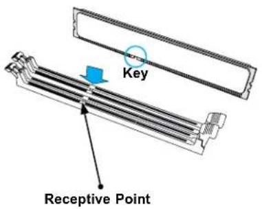
- Insert the desired number of DIMMs into the memory slots, there is no specific sequence or order required.
- Push the release tabs outwards on both ends of the DIMM slot to unlock it.
- Align the key of the DIMM module with the receptive point on the memory slot.
- Align the notches on both ends of the module against the receptive points on the ends of the slot.
- Press both ends of the module straight down into the slot until the module snaps into place.
- Press the release tabs to the lock positions to secure the DIMM module into the slot.
DIMM Removal
Press both release tabs on the ends of the DIMM module to unlock it. Once the DIMM module is loosened, remove it from the memory slot.
text_image
Key Receptive Point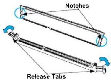
text_image
Notches Release Tabs
text_image
Press both ends straight down into the memory slot.Motherboard Battery
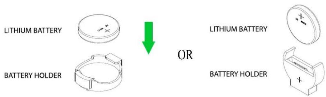
The motherboard uses non-volatile memory to retain system information when system power is removed. This memory is powered by a lithium battery residing on the motherboard.
Replacing the Battery
Begin by removing power from the system as described in Section 3.1.
- Push aside the small clamp that covers the edge of the battery. When the battery is released, lift it out of the holder.
- To insert a new battery, slide one edge under the lip of the holder with the positive (+) side facing up. Then push the other side down until the clamp snaps over it.
Note: Handle used batteries carefully. Do not damage the battery in any way; a damaged battery may release hazardous materials into the environment. Do not discard a used battery in the garbage or a public landfill. Please comply with the regulations set up by your local hazardous waste management agency to dispose of your used battery properly.
text_image
LITHIUM BATTERY BATTERY HOLDER OR LITHIUM BATTERY BATTERY HOLDERFigure 3-5. Installing the Onboard Battery
Warning: There is a danger of explosion if the onboard battery is installed upside down (which reverses its polarities). This battery must be replaced only with the same or an equivalent type recommended by the manufacturer (CR2032).
3.6 Chassis Components
Storage Drives
The CSE-GT214BC chassis supports up to 24 storage drives (up to six 2.5" drives per node) in drive carriers to simplify their removal from the chassis. These carriers also help promote proper airflow.
Drive Carrier Indicators
Each drive carrier has two LED indicators: an activity indicator and a status indicator. For RAID configurations using a controller, the meaning of the status indicator is described in the table below. For OS RAID or non-RAID configurations, some LED indications are not supported, such as hot spare.
| Drive Carrier LED Indicators | |||
| Color Blinking Pattern Behavior for Device | |||
| Activity LED | Blue Solid On Idle NVMe drive installed | ||
| Blue Blinking I/O activity | |||
| Blue Off Idle SATA drive installed | |||
| Status LED | Green Solid Green LED Safe to remove NVMe device | ||
| Amber Blinking at 1Hz Do not remove NVMe device | |||
Note: Enterprise level drives are recommended for use in Supermicro chassis and servers. For information on recommended storage drives, visit the Supermicro website product pages at www.supermicro.com/products.
Drive Configuration
The CSE-GT214BC chassis contains four separate computing node drawers, each with its own motherboard. Each node controls a set of six drives. If a node drawer is pulled out of the chassis, the drives associated with that node will power down.
| Node Drawer Locations | |
| Node B controls drives B0, B1, B2, B3, B4, and B5 Node | D controls drives D0, D1, D2, D3, D4, and D5 |
| Node A controls drives A0, A1, A2, A3, A4, and A5 | Node C controls drives C0, C1, C2, C3, C4, and C5 |
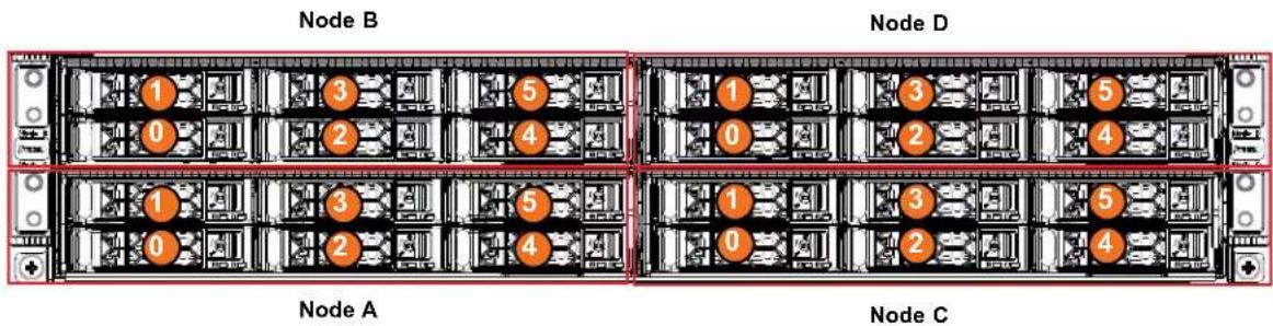
text_image
Node B Node D 1 3 5 0 2 4 1 3 5 0 2 4 1 3 5 0 2 4 Node A Node CFigure 3-6. Node/Drive locations
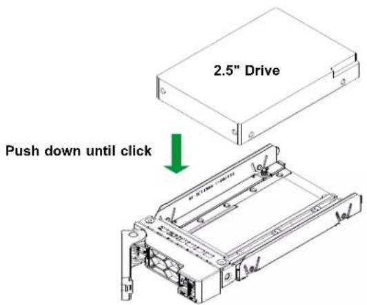
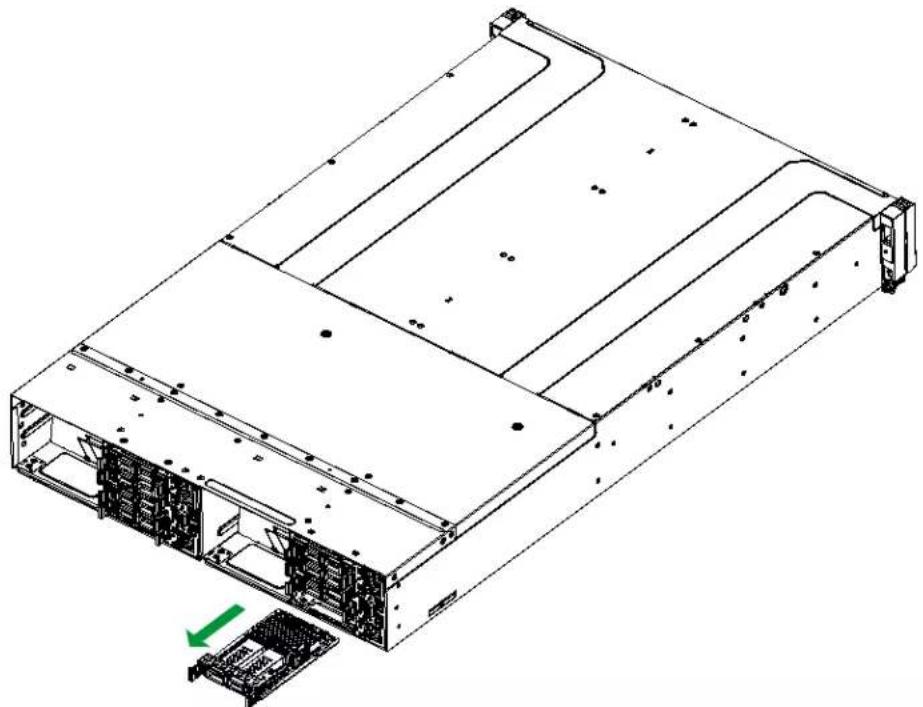
Removing/Installing Drives
Removing a Drive Carrier from the Chassis
- Push the release button on the drive carrier. This releases and extends the drive carrier handle. If the release button does not release it, the handle may be locked. Use a flathead screwdriver and rotate the screw counterclockwise 45 degrees to unlock the handle.
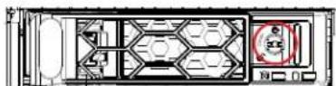
Figure 3-7. Unlocking the Handle
- Use the handle to pull the carrier out of the chassis as shown below.
Caution: To ensure proper airflow, do not operate the server with the drive carriers removed from the bays except for short periods of time (swapping drives), regardless of how many drives are installed.
text_image
Diagram illustrating server rack connection with labeled components and directional arrows indicating rotation or data transfer.Figure 3-8. Removing a Drive Carrier
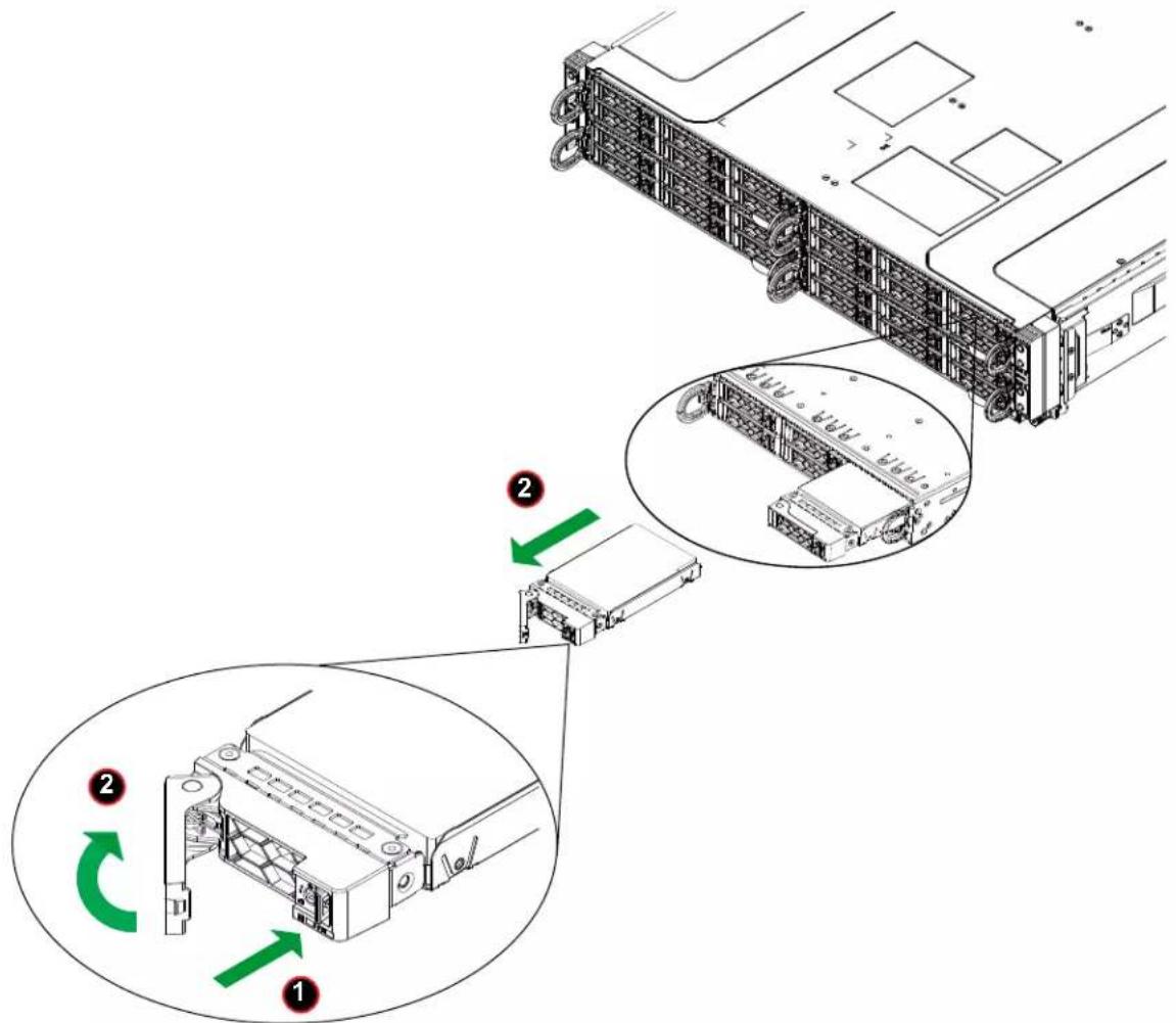
Installing a 2.5" Drive into the Drive Tray
- Place the drive carrier on a flat surface.
- Orient the drive with the connector facing the bottom rear of the carrier. The drive can be inserted from above into the clips until a "click" is heard.
- Use the open handle of the drive carrier to insert the carrier into the open drive bay.
- Secure the drive carrier into the drive bay by closing the drive carrier handle.
- Lock the handle with a flat-head screwdriver.
text_image
2.5" Drive Push down until clickFigure 3-9. Installing a 2.5" Drive
Removing a 2.5" Hard Drive
- After removing the carrier from the system, push up from the bottom of the drive to remove it from the carrier.
- Replace with a new drive and insert the carrier back into the open drive bay.

text_image
Push up from bottomFigure 3-10. Removing a 2.5" Drive
Hot-Swap for NVMe Drives
Supermicro servers support NVMe surprise hot-swap. For even better data security, NVMe orderly hot-swap is recommended. NVMe drives can be ejected and replaced remotely using BMC.
Ejecting a Drive
- BMC > System > Storage Monitoring > Physical View
- Select Device, Group and Slot, and click Eject. After ejecting, the drive Status LED indicator turns green.
- Remove the drive.
Note that Device and Group are categorized by the CPLD design architecture. The SYS-211GT-HNTR/HNC8R server has one Device and one Group.
Slot is the slot number on which the NVMe drives are mounted.
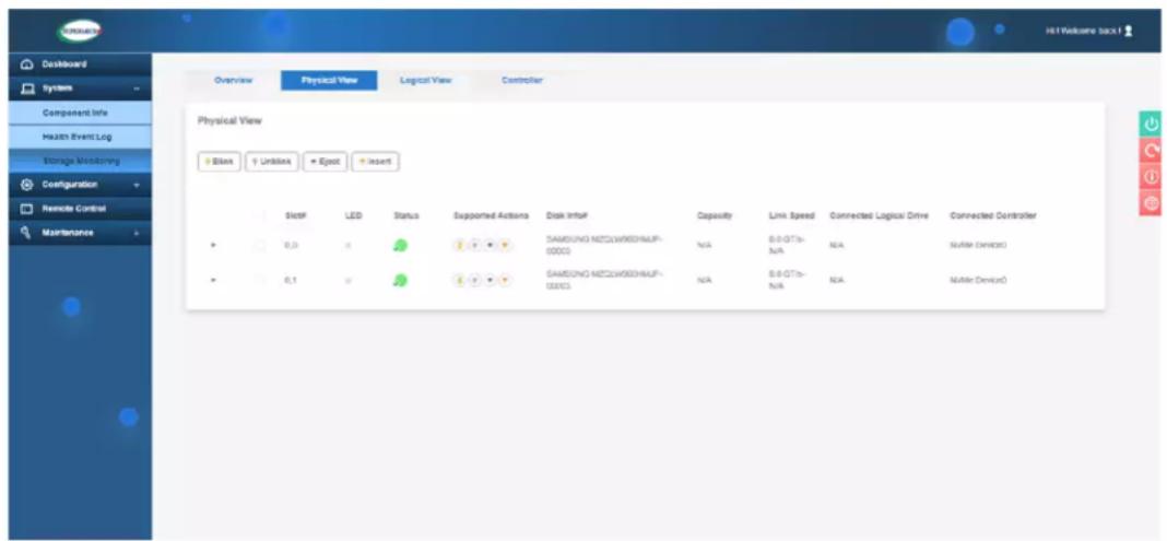
text_image
Overview Physical View Logical View Controller Physical View + Blank + Unblank + Eject + Insert Slot LED Status Supported Actions Disk Influf Capacity Limit Speed Connected Logical Drive Connected Controller 0,0 0,1 GAMSUNG METCLOWSH06HAUF-00003 N/A 8.0 GT/- N/A N/A NAMr Device0 GAMSUNG METCLOWSH06HAUF-00003 N/A 8.0 GT/- N/A N/A NAMr Device0Figure 3-11. BMC Screenshot
Replacing the Drive
- Insert the replacement drive.
- BMC > System > Storage Monitoring > Physical View
- Select Device, Group and slot and click Insert. The drive Status LED indicator flashes red, then turns off. The Activity LED turns blue.
Checking the Temperature of an NVMe Drive
There are two ways to check using BMC.
Checking a Drive
- BMC > Storage Monitoring > Physical View – Shows the temperatures of all NVMe drives.
- BMC > Sensor Reading – Shows the single highest temperature among all the NVMe drives.
AIOM Card
A Supermicro Advanced Input/Output Module (AIOM) provides options for network connection when inserted into an AIOM slot on the motherboard tray. The following AIOM cards may be used with the SYS-211GT-HNTR/HNC8R: AOC-ATGC-i2TM, AOC-A25G-m2SM, and AOC-A25G-i2SM. See web page for details.
Removing the AIOM Card
- Press the release tab and loosen the thumbscrew on the AIOM card.
- Grasp the release tab and the thumbscrew and pull the AIOM out of the chassis.
natural_image
Technical line drawing of a server rack with internal components and a green arrow indicating a specific part (no text or symbols present)Figure 3-12. AIOM Card Position
Installing the AIOM Card
- Insert the AIOM card into the slot as shown until the release tab retracts.
- Tighten the thumbscrew.
I/O Card Module
The I/O card module provides options for input/output connections for different devices. It is inserted into the I/O slot in the chassis.
Removing the I/O Card Module
- Power down the system as described in Section 3-1 and remove the cover.
- Remove cables that are connected from the power distributor backplane.
Caution: Make sure that all cables are out of the way before proceeding.
-
Loosen and remove the two screws securing the module to the chassis.
-
Gently pull the I/O card module out of the chassis.

text_image
Technical diagram of a server rack with labeled components and directional arrows indicating assembly or movement.Figure 3-13. I/O Card Position at Rear
Installing the I/O Card Module
- Align the replacement module with the empty slot and carefully slide the I/O card module into the slot at the rear of the server.
- Install and tighten the two screws on the top of the chassis.
- With the I/O module in, attach cables to the power distributor backplane.
- Power the system back on.
3.7 System Cooling
Fans
Fan speed is controlled by a system temperature setting in IPMI. If a fan fails, the remaining fans will ramp up to full speed. Replace any failed fan at your earliest convenience with the same type and model.
Changing a System Fan
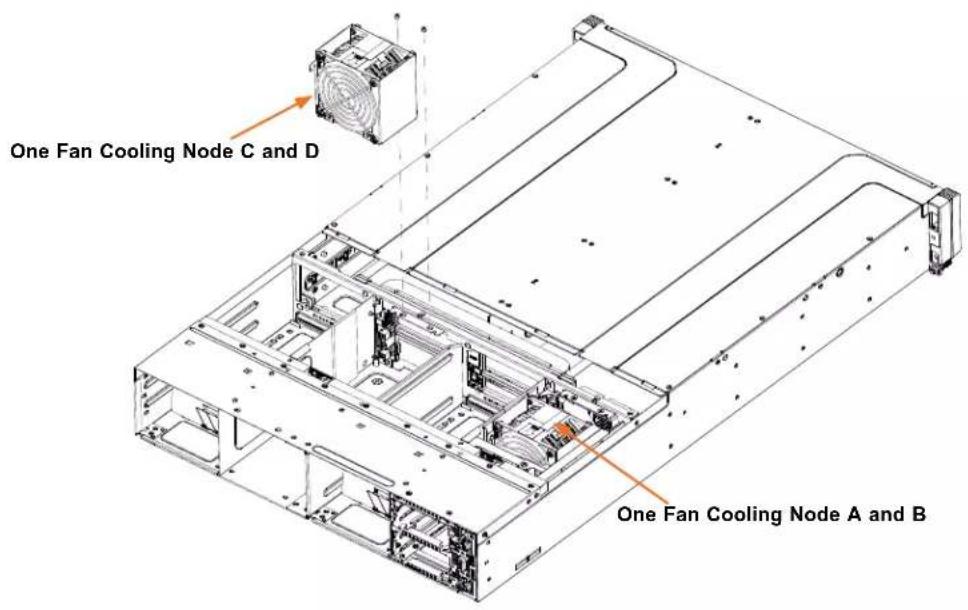
text_image
One Fan Cooling Node C and D One Fan Cooling Node A and BFigure 3-14. Removing System Fans
- Determine which fan is failing. If possible, use IPMI. If not, while the power is on, examine the fans to determine which one has failed.
- Remove power from the system as described in Section 3.1.
- Remove the fan cable from the midplane for the failed fan.
- Lift the fan housing up and out of the chassis.
- Push the fan up from the bottom.
- Put the new fan back into the chassis and reconnect the cable.
- Power on the system to confirm that the fan is working properly before replacing the chassis cover.
Installing the Air Shroud
Air shrouds help to funnel the airflow provided by the fans over the system components that generate the most heat. The system requires air shrouds for each node to maximize airflow efficiency. The motherboard, any expansion cards, and all components must be installed in the node tray. Place the air shroud as pictured and secure with a screw.
Installing the Air Shroud
- First, ensure the CPU, CPU heatsinks, and configured DIMMs are installed.
- Align the mountings screw holes in the plastic air shroud with those in the node interior and lower the air shroud into the node until it is firmly seated.
- Secure the air shroud with the two tall standoffs provided. Be careful that the air shroud legs at either end do not interfere with any motherboard components such as cables.
- Secure the cable protector with the two screws tightened on top of the two tall standoffs in order to cover or manage any loose cables that interfere with the air shroud placement.
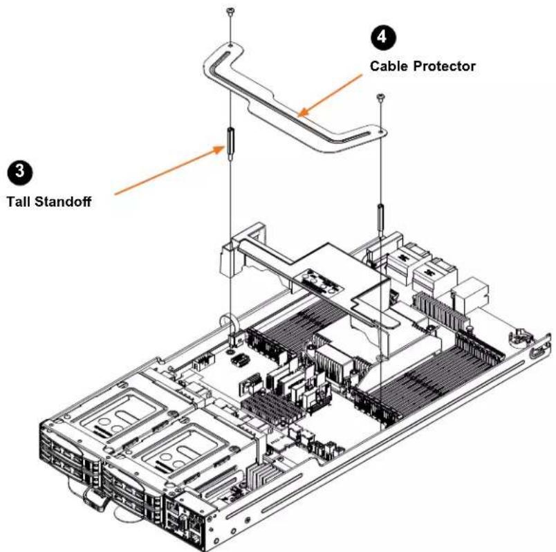
text_image
Cable Protector Tall StandoffFigure 3-15. Installing the Air Shroud
3.8 Power Supply
The chassis features dual redundant power supplies. The power modules can be changed without powering down the system. Please exchange the power modules within one minute. New units can be ordered directly from Supermicro or authorized distributors.
These power supplies are auto-switching capable. This feature enables them to automatically sense the input voltage and operate at a 100-120 VAC or 180-240 VAC. An amber light will be illuminated on the power supply when the power is o . An illuminated green light indicates that the power supply is operating.
Replacing the Power Supply
- Unplug the AC cord from the module to be replaced.
- Release the locking clip to unlock the power supply module
- Pull out the locking lever and remove the unit. To release the lever, squeeze the two metal plates of the lever with your thumb and ngers, and then pull the module out.

text_image
Locking Clip Locking LeverFigure 3-16. Power Supply Release Tab
- Replace the failed power module with the same model.
- Push the new power supply module into the power bay until it clicks.
- Plug the AC power cord back into the module.
3.9 Cable Routing Diagram
Refer to the diagrams below for representations of how the NVMe and AIOM cables are routed throughout the system. When disconnecting cables to add or replace components, refer to these diagrams so you can reroute them in the same manner. Proper cable routing is important in maintaining proper airflow through the system.
6x NVMe + 2x AIOM
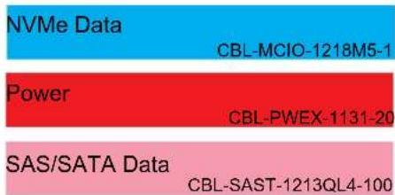
text_image
NVMe Data CBL-MCIO-1218M5-1 Power CBL-PWEX-1131-20 SAS/SATA Data CBL-SAST-1213QL4-100Online Cable Matrix

text_image
NVMe-1 NVMe-3 NVMe-5 NVMe-0 NVMe-2 NVMe-4 AIOM-NIC2 (no NSCI) AIOM-NIC1 (NCSI) AIOM-NIC2 (no NCSI) AIOM-NIC1 (NCSI) Upper Node (B/D) Lower Node (A/C)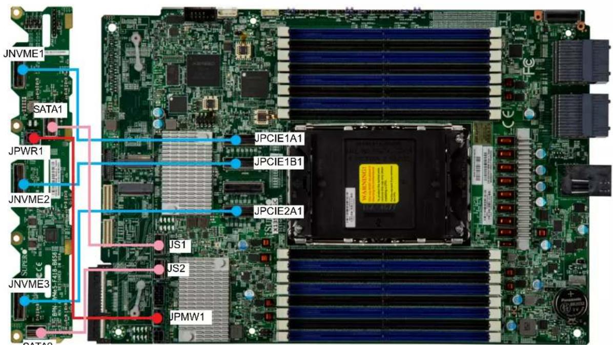
text_image
JNVME1 SATA1 JPWR1 JNVME2 JNVME3 SATA2 JPCIE1A1 JPCIE1B1 JPCIE2A1 JS1 JS2 JPMW1MotherboardBackplane
3.9 BMC Reset
The BMC can be reset using the button on the front control panel or on the chassis rear.
- Reset – Press and hold the button. After six seconds, the LED blinks at 2 Hz. The BMC resets and the reset duration is \~250 ms. Then the BMC starts to boot.
- Restore factory default configuration – Hold the button for twelve seconds. The LED blinks at 4 Hz while defaults are configured.
Note: All BMC settings including username and password will be removed except the FRU and network settings.
| BMC Reset Options | ||
| Event UID LED BMC Heartbeat LED | ||
| Reset Blue, Blinks at 2 Hz Green, solid | ||
| Restore Defaults Blue, Blinks at 4 Hz Green, solid | ||
Chapter 4
Motherboard Connections
This section describes the connections, jumpers and LED indicators on the motherboard and provides pinout definitions. Not all connections are required. A motherboard layout indicating component locations may be found in Chapter 1.
Please review the Safety Precautions in Appendix A before installing or removing components.
4.1 Power Connections
Power Connectors
JPWR1 is a 12 V connector that connects to the back and middle plane, BPN-PDB-GT214. The power supply also connects to BPN-PDB-GT214 to provide power to the motherboard.
4.2 Headers and Connectors
COM Header
The motherboard has one COM header (COM1) that provides a serial connection.
| COM Header (COM1)Pin Definitions | |||
| Pin# Definition Pin# Definition | |||
| 1 DCD | 2 DSR | ||
| 3 RXD | 4 RTS | ||
| 5 TXD | 6 CTS | ||
| 7 DTR | 8 RI | ||
| 9 Ground 10 N/A | |||
4-pin External BMC I²C Header
A System Management Bus header for IPMI 2.0 is located at JIPMB1. Connect a cable to this header to use the IPMB I ^2 C connection on your system. Refer to the table below for pin definitions.
| External I2C Header Pin Definitions | |
| Pin# | Definition |
| 1 Data | |
| 2 Ground | |
| 3 Clock | |
| 4 No Connection | |
Fan Headers
There is one 4-pin fan header (FAN1) on the motherboard. The 4-pin fan header is backwards compatible with the traditional 3-pin fans. However, fan speed control is available for 4-pin fans only by Thermal Management via the IPMI 2.0 interface. Refer to the table below for pin definitions.
| Fan HeaderPin Definitions | |
| Pin# | Definition |
| 1 | Ground (Black) |
| 2 | 2.5A/+12V (Red) |
| 3 | Tachometer |
| 4 | PWM_Control |
Intel RAID Key Header
The JRK1 header allows you to enable RAID functions for NVMe connections. Refer to the table below for pin definitions.
| Intel RAID Key HeaderPin Definitions | |
| Pin# Definition | |
| 1 GND | |
| 2 PU 3.3 V Stdby | |
| 3 | GND |
| 4 | PCH RAID KEY |
M.2 Slots
This motherboard has two M.2 slots (JMD1, JMD2). M.2 was formerly known as Next Generation Form Factor (NGFF) and serves to replace mini PCIe. M.2 allows for a variety of card sizes, increased functionality, and spatial efficiency. The M.2 slots on the motherboard supports PCIe 3.0 x4 or SATA from the PCH, one in the 2280 form factors.
NC-SI Connector
A Network-Controller Sideband Interface (NC-SI) header is located at JNCSI1 on the motherboard. The NC-SI header is used to connect a Network Interface Card (NIC) to the motherboard so that the BMC is able to poll the temperature reading from it.
Note: For detailed instructions on how to configure Network Interface Card (NIC)settings, refer to the Network Interface Card Configuration User's Guide posted on the web page under the link: http://www.supermicro.com/support/manuals/.
SAS and SATA Ports
This motherboard has two SlimSAS connectors located at JS1 and JS2 to support six SATA (SATA0-SATA5) devices.
TPM/Port 80 Header
A Trusted Platform Module (TPM)/Port 80 header is located at JTPM1 to provide TPM support and Port 80 connection. Use this header to enhance system performance and data security. Refer to the table below for pin definitions. Go to the following link for more information on the TPM: http://www.supermicro.com/manuals/other/TPM.pdf.
| Trusted Platform Module Header Pin Definitions | |
| Pin# Definition Pin# Definition | |
| 1 +3.3V 2 SPI_CS# | |
| 3 RESET# 4 SPI_MISO | |
| 5 SPI_CLK 6 GND | |
| 7 SPI_MOSI 8 NC | |
| 9 +3.3V Stdby 10 SPI_IRQ# | |
Molex Impel Plus Connectors
J35 and J40 are PCIe connectors that connect to the PCIe backplane. The connectors can support AIOM backplanes and NVMe backplanes.
MCIO Connectors
JPCIE1A1, JPCIE1B1, JPCIE2A1 and JPCIE2B1 are PCIe connectors that connect to the PCIe backplane. These connectors can support AIOM backplanes, NVMe backplanes and riser cards.
4.3 Jumper Settings
How Jumpers Work
To modify the operation of the motherboard, jumpers can be used to choose between optional settings. Jumpers create shorts between two pins to change the function of the connector. Pin #1 is identified with a thicker border line on the printed circuit board. See the diagram below for an example of jumping pins 1 and 2. Refer to the motherboard layout page for jumper locations.
Note: On two-pin jumpers, "Closed" means the jumper is on and "Open" means the jumper is off the pins.

text_image
Connector Pins Jumper Setting 3 2 1 Pin#1 3 2 1Clear CMOS (JBT1)
JBT1 is used to clear CMOS, which will also clear any passwords. Instead of pins, this jumper consists of contact pads to prevent accidentally clearing the contents of CMOS.
To Clear CMOS
- First power down the system and unplug the power cord(s).
- Remove the cover of the chassis to access the motherboard.
- Remove the CMOS battery from the motherboard.
- Short the CMOS pads with a metal object such as a small screwdriver for at least four seconds.
- Remove the screwdriver (or shorting device).
- Re-install the CMOS battery on the motherboard.
- Replace the cover, reconnect the power cord(s), and power on the system.
Note: Clearing CMOS will also clear all passwords.
Do not use the PW_ON connector to clear CMOS.

JBT1 contact pads
Backplane or Riser Card/AIOM Enable
Use the JI²C1 (JPCIEA1) and JI²C2 (JPCIEB1) jumpers to enable backplane or riser card/AlOM features. The backplane supports NVMe while the riser card/AlOM supports standard PCIe devices and AlOM cards. Refer to the table below for jumper settings.
| JI2C1 (JPCIEA1) and JI2C2 (JPCIEB1)Jumper Settings |
| Jumper Setting Definition |
| Pins 0-1 Backplane |
| Pins 1-2 RSC/AlOM |
ME Manufacturing Mode
Close JPME2 to bypass SPI flash security and force the system to use the Manufacturing Mode, which will allow the user to flash the system firmware from a host server to modify system settings. Refer to the table below for jumper settings.
| Manufacturing ME ModeJumper Settings | |
| Jumper Setting Definition | |
| Pins 1-2 Normal (Default) | |
| Pins 2-3 Manufacturing Mode |
Watch Dog
JWD1 controls the Watch Dog function. Watch Dog is a monitor that can reboot the system when a software application hangs. Jumping pins 1-2 will cause Watch Dog to reset the system if an application hangs. Jumping pins 2-3 will generate a non-maskable interrupt signal for the application that hangs. Watch Dog must also be enabled in BIOS. The default setting is Reset.
Note: When Watch Dog is enabled, users need to write their own application software to disable it.
| Watch DogJumper Settings | |
| Jumper Setting Definition | |
| Pins 1-2 Reset (Default) | |
| Pins 2-3 NMI | |
| Open Disabled | |
4.4 LED Indicators
BMC Heartbeat LED
LEDM1 is the BMC Heartbeat LED. When the LED is blinking green, BMC is working. Refer to the table below for the LED status.
| BMC Heartbeat LED | |
| LED Color Definition | |
| Green: Blinking BMC Normal | |
| Red BMC Error | |
SAS Heartbeat LED
LESDS2 is the SAS Heartbeat LED. When the LED is solid red, there is an error with the SAS. Refer to the table below for the LED status.
| SAS ActivityLED Indicator | |
| LED Color Definition | |
| Green: Blinking SAS | Active |
| Red SAS Error | |
UID LED
LED1 is the Unit Identifier LED. When you press the UID switch, the UID LED will be turned on. Press the UID switch again to turn off the LED indicator. The UID Indicator provides easy identification of a system unit that may be in need of service.
Note: UID can also be triggered via IPMI on the motherboard. For more information on IPMI, please refer to the IPMI User's Guide posted on our website at http://www.supermicro.com/support/manuals/.
| UID LEDPin Definitions | |
| Color Status | |
| Blue: On Unit Identified |
Chapter 5
Software
After the hardware has been installed, you can install the Operating System (OS) and install the drivers.
5.1 Microsoft Windows OS Installation
Installing the OS
- Create a method to access the Microsoft Windows installation ISO file. That can be a USB flash or media drive.
- Go to the Supermicro web page for your motherboard and click on "Download the Latest Drivers and Utilities", select the proper driver, and copy it to a USB flash or media drive.
- Boot from a bootable device with Windows OS installation. You can see a bootable device list by pressing
during the system startup.
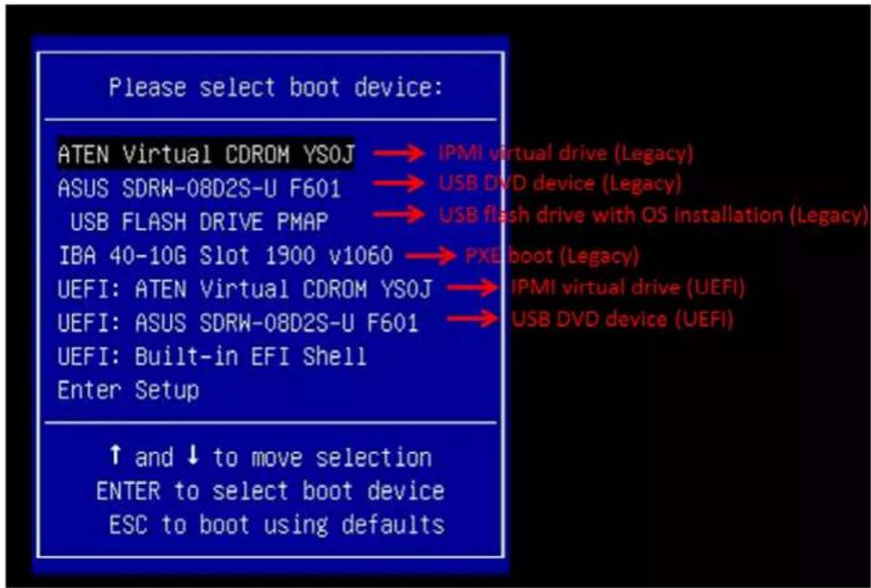
text_image
Please select boot device: ATEN Virtual CDROM YSOJ → IPMI virtual drive (Legacy) ASUS SDRW-08D2S-U F601 → USB DVD device (Legacy) USB FLASH DRIVE PMAP → USB flash drive with OS installation (Legacy) IBA 40-10G Slot 1900 v1060 → PXE boot (Legacy) UEFI: ATEN Virtual CDROM YSOJ → IPMI virtual drive (UEFI) UEFI: ASUS SDRW-08D2S-U F601 → USB DVD device (UEFI) UEFI: Built-in EFI Shell Enter Setup ↑ and ↓ to move selection ENTER to select boot device ESC to boot using defaultsFigure 5-1. Select Boot Device
- During Windows Setup, continue to the dialog where you select the drives on which to install Windows. If the disk you want to use is not listed, click on "Load driver" link at the bottom left corner.
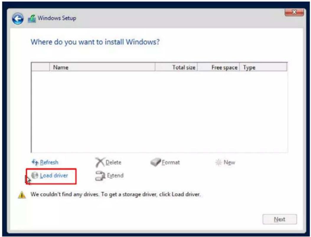
text_image
Where do you want to install Windows? Name Total size Free space Type Refresh Delete Format New Load driver Extend We couldn't find any drives. To get a storage driver, click Load driver. NextFigure 5-2. Load Driver Link
To load the driver, browse the USB flash or media drive for the proper driver files.
- For non-RAID, choose the SATA/sSATA AHCI driver indicated then choose the storage drive on which you want to install it.
- Once all devices are specified, continue with the installation.
- After the Windows OS installation has completed, the system will automatically reboot multiple times.
5.2 Driver Installation
The Supermicro website contains drivers and utilities for your system at https://www.supermicro.com/wdl/. Some of these must be installed, such as the chipset driver.
After accessing the website, go into the CDR_Images (in the parent directory of the above link) and locate the ISO file for your motherboard. Download this file to a USB flash or media drive. (You may also use a utility to extract the ISO file if preferred.)
Another option is to go to the Supermicro website at http://www.supermicro.com/products/. Find the product page for your motherboard, and "Download the Latest Drivers and Utilities". Insert the flash drive or disk and the screenshot shown below should appear.

text_image
SUPERMICRO X13SET-G Motherboard Drivers & Tools (Win11) Intel Chipset INF files Microsoft .Net Framework 4.8(Optional) Intel Virtual RAID on LPU Intel PRO Network Connections Drivers SUPERMICRO SuperDoctor 5 Build driver diskettes and manuals Browse CD Auto Start Up Next Time For more information, please visit SUPERMICRO's web site.Figure 5-3. Driver and Tool Installation Screen
Note: Click the icons showing a hand writing on paper to view the readme files for each item. Click the computer icons to the right of these items to install each item (from top to the bottom) one at a time. After installing each item, you must re-boot the system before moving on to the next item on the list. The bottom icon with a CD on it allows you to view the entire contents.
5.3 SuperDoctor®5
The Supermicro SuperDoctor 5 is a program that functions in a command-line or web-based interface for Windows and Linux operating systems. The program monitors such system health information as CPU temperature, system voltages, system power consumption, fan speed, and provides alerts via email or Simple Network Management Protocol (SNMP).
SuperDoctor 5 comes in local and remote management versions and can be used with Nagios to maximize your system monitoring needs. With SuperDoctor 5 Management Server (SSM Server), you can remotely control power on/off and reset chassis intrusion for multiple systems with SuperDoctor 5 or IPMI. SuperDoctor 5 Management Server monitors HTTP, FTP, and SMTP services to optimize the efficiency of your operation.
SuperDoctor® Manual and Resources

text_image
SuperMicro SuperDucts Certificure error localhost HA/SupercSource SuperDoctor 5 Health info Motherboard: C7B360-CB-ML Voltage Temperature Hard Disk Memory Select language English JAMWK Logistic Status Device Inverter 210V Time 210V Time 210V Time 210V Time 210V Time 210V Time 210V Time 210V Time 210V Time 210V Time 210V Time 210V Time 210V Time 210V Time 210V Time 210V Time 210V Time 21V Time 21V Time 21V Time 21V Time 21V Time 21V Time 21V Time 21V Time 21V Time 21V Time 21V Time 21V Time 21V Time 21V Time 21V Time 21V Time 21V Time 21V Time 21V Time 21V Time 20V Time 20V Time 20V Time 20V Time 20V Time 20V Time 20V Time 20V Time 20V Time 20V Time 20V Time 20V Time 20V Time 20V Time 20V Time 20V Time 20V Time 20V Time 20V Time 20V Time 25V Time 25V Time 25V Time 25V Time 25V Time 25V Time 25V Time 25V Time 25V Time 25V Time 25V Time 25V Time 25V Time 25V Time 25V Time 25V Time 25V Time 25V Time 25V Time 25V Time 24V Time 24V Time 24V Time 24V Time 24V Time 24V Time 24V Time 24V Time 24V Time 24V Time 24V Time 24V Time 24V Time 24V Time 24V Time 24V Time 24V Time 24V Time 24V Time 24V Time 23A38.6.6.6.6.6.6.6.6.6.6.6.6.6.6.6.6.6.6.6.6.6.6.6.6.6.6.6.6.6.6.6.6.6.6.6.6.6.6.6.6.6.6.6.6.6.6.6.6.6.6. 37A38.6.6.6.6.6.6.6.6.6.6.6.6.6.6.6.6.6.6.6.6.6.6.6.6.6.6.6.6.6.6.6 37A38.6.6.6.6.6.6.6.6.6.6 37A38.6 37A38 37A38 37A38 37A38 37A38 37A38 37A38 37A38 37A38 37A38 37A38 37A38 37A38 37A38 37A38 37A38 37A38 37 A38 37A38 37A38 37A38 37A38 37A38 37A38 37A38 37A38 37A38 37A38 37A38 37A38 37A38 37A38 37A38 37A38 09A38 09A38 09A38 09A38 09A38 09A38 09A38 09A38 09A38 09A38 09A38 09A38 09A38 09A38 09A38 09A38 09A38Figure 5-4. SuperDoctor 5 Interface Display Screen (Health Information)
5.4 IPMI
The X13SET-G/GC supports the Intelligent Platform Management Interface (IPMI). IPMI provides remote access, monitoring and management through the baseboard management controller (BMC) and other management controllers distributed among different system modules. There are several BIOS settings that are related to IPMI. For general documentation and information on IPMI, visit our website at: http://www.supermicro.com/products/nfo/IPMI.cfm.
BMC ADMIN User Password
For security, each system is assigned a unique default BMC password for the ADMIN user. This can be found on a sticker on the chassis and a sticker on the motherboard. The sticker also displays the BMC MAC address.

text_image
BMC AC1F6BC PWD SUOKJFigure 5-5. BMC Password Label
See Chapter 1 for the location of the label.
Chapter 6
Optional Components
This chapter describes optional system components and installation procedures.
6.1 Optional Parts List
| Optional Parts List | ||
| Description Part Number Quantity (Max.) | ||
| Front window dummy cover for rear I/O node tray | MCP-120-21408-0N | 2 |
| SPI capable TPM 2.0 AOM-TPM-9670V-S n/a | ||
6.2 Intel Virtual RAID on CPU (VROC)
Intel® Virtual RAID on CPU (Intel VROC) is an enterprise RAID solution for NVMe SSDs directly attached to Intel Xeon Scalable processors. Intel Volume Management Device (VMD) is an integrated controller inside the CPU PCIe root complex.
- A single processor supports up to 12 NVMe SSDs and up to 6 RAID arrays.
- A dual processor system supports up to 24 NVMe SSDs and 12 RAID arrays.
Strip sizes are 4K, 8K, 16K, 32K, 64K, 128K.
Requirements and Restrictions
- Intel VROC is only available when the system is configured for UEFI boot mode.
-
To enable the mdadm command and support for RSTe, install the patch from
-
Linux: https://downloadcenter.intel.com/download/28158/Intel-Virtual-RAID-on-CPU-Intel-VROC-and-Intel-Rapid-Storage-Technology-enterprise-Intel-RSTe-Driver-for-Linux
-
Windows: https://downloadcenter.intel.com/download/28108/Intel-Virtual-RAID-on-CPU-Intel-VROC-and-Intel-Rapid-Storage-Technology-enterprise-Intel-RSTe-Driver-for-Windows
-
To enable Intel VROC, a hardware key must be inserted on the motherboard, and the appropriate processor's Virtual Management Devices must be enabled in the BIOS setup.
- It is possible to enable Intel VROC without a hardware key installed, but only RAID0 will be enabled.
- Intel VROC is not compatible with secure boot. This feature must be disabled.
- When creating bootable OS RAID1 devices, you must have both devices on the same CPU, and a VMD on that CPU.
- Spanning drives when creating RAID devices is not recommended to due to performance issues, even though it is supported.
Supported SSDs and Operating Systems
To see the latest support information: https://www.intel.com/content/www/us/en/support/articles/000030310/memory-and-storage/ssd-software.html
Additional Information
Additional information is available on the product page for the Supermicro add-on card and the linked manuals.
www.supermicro.com/products/accessories/addon/AOC-VROCxxxMOD.cfm
Hardware Key
The Intel VROC hardware key is a license key that detects the Intel VROC SKU and activates the function accordingly. The key must be plugged into the Supermicro motherboard (connector JRK1). The key options are:
| Intel® VROC Keys | |||
| VROC Package Description Part Number Intel MM Number | |||
| Standard | RAID 0, 1, 10Supports 3rd party SSDs | AOC-VROCSTNMOD 95 | 1605 |
| Premium | RAID 0, 1, 5, 10Supports 3rd party SSDs | AOC-VROCPREMOD 95 | 1606 |
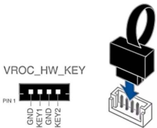
text_image
VROC_HW_KEY PIN 1 GND KEY1 GND KEY2Figure 6-1. Intel® VROC RAID Key and Motherboard Connector JRK1
Enabling NVMe RAID
RAID for NVMe SSDs must be enabled through the UEFI BIOS.
- Install the patch as described in the Restrictions and Requirements section on a previous page.
- Reboot the server.
- Press [DEL] key to enter BIOS.
- Switch to Advanced > Chipset Configuration > North Bridge > IIO Configuration > Intel® VMD Technology > CPU3 & CPU4.
-
Enable the VMD according to the following rules.
-
For U.2 NVMe, enable all the sub-items under each PStack, based on the your model server:
- For M.2 NVMe or NVMe AIC, enable the VMD according to which AOC card/slot it used.
Examples for some U.2 configurations follow.
- Press [F4] to save the configuration and reboot the system.
- Press [DEL] to enter BIOS.
- Switch to Advanced > Intel(R) Virtual RAID on CPU > All Intel VMD Controllers > Create RAID Volume.
- Set Name.
- Set RAID Level.
- If cross-controller RAID is required, select Enable RAID spanned over VMD Controller as shown in Figure 6-4.
- Select specific disks for RAID with an [X].
• RAID0: Select at least two [2 - 24] disks
• RAID1: Select only two disks
• RAID5: Select at least three [3 - 24] disks
• RAID10: Select only four disks
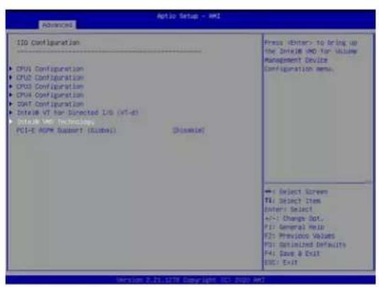
text_image
Optio Setup - AMI ISO Configuration CPU1 Configuration CPU2 Configuration CPU3 Configuration CPU4 Configuration SWT Configuration SDEUB VT Non-Directed Ltd (VT-d) InteAM IWD Technologies PCI-E ASPM Support (Custes) [Disable] Press Editors to bring up the Interior AMD for Volume Management Device. Configuration menu. -> Select Screen F1: Object Item Enter: Select +/- Change Opt. F1: General Help F2: Previous Values F3: Validated Defaults F4: Dave & Exit ESC: Exit Version 0.71.1278 Copyright 167.1278 AMI
text_image
Aptio Setup - AMI Advanced Intie8 VMD Technology • Intie8 VMD for Volume Management Device on CPU • Intie8 VMD for Volume Management Device on CPU • Intie8 VMD for Volume Management Device on CPU +1 Select Screen F1: Select Item Enter Select +/-1 Change Out. F1: General Info F2: Previous Values F3: Default Defaults F4: Dev & Exit F5: Exit Version 0.71.179 Copyright 05.1.2020.dwt
text_image
Advanced VMD Config for 200 S Enable/Disable VMD None12 VMD None13 VMD None14 VMD None15 VMD Hot Plug Capable VMD Config for 200 S Enable/Disable VMD None13 VMD None18 VMD None17 VMD None18 VMD Hot Plug Capable VMD Config for 200 S Enable/Disable VMD None26 VMD None21 VMD None22 VMD None23 VMD Hot Plug Capable Enable/Disable Enable/Disable Hot Plug for PCIe Root Ports Enable/Disable Hot Plug for PCIe Root Ports Enable/Disable Hot Plug for PCIe Root Ports Enable/Disable Hot Plug for PCIe Root Ports Enable/Disable Hot Plug for PCIe Root Ports Enable/Disable Hot Plug for PCIe Root Ports Enable/Disable Hot Plug for PCIe Root Ports Enable/Disable Hot Plug for PCIe Root Ports Enable/Disable Hot Plug for PCIe Root Ports Enable/Reduce Screen TA: Select Item Enter: Select +/- Change Opt. F1: General Hubs F2: Previous Values F3: Optimized Defaults F4: Save & Exit F5: Exit
text_image
Auto Setup - v8 Advanced VMD Config for 100.0 Enable/Disable VMD VMed VMD VMed1 VMD VMed2 VMD VMed3 VMD Hot Plug Capable VMD Config for 100.0 Enable/Disable VMD VMed7 VMD VMed5 VMD VMed5 VMD VMed4 VMD Hot Plug Capable VMD Config for 100.0 Enable/Disable VMD VMed9 VMD VMed5 VMD VMed3 VMD VMed1 VMD Hot Plug Capable Enable/Disable VMD VMed6 VMD VMed5 VMD VMed3 VMD VMed2 VMD VMed1 VMD Hot Plug Capable Enable/Disable VMD VMed7 VMD VMed5 VMD VMed3 VMD VMed2 VMD VMed1 VMD Hot Plug Capable Enable/Disable VMD VMed7 VMD VMed5 VMD VMed3 VMD VMed2 VMD VMed1 VMD Hot Plug Capable Enable/Disable VMD VMed7 VMD VMed5 VMD VMed3 VMD VMed1 VMD Hot Plug Capable Enable/Disable VMD VMed7 VMD VMed5 VMD VMed3 VMD VMed2 VMD VMed1 VMD Hot Plug Capable Enable/Disable VMD VMed7 VMD VMed5 VMD VMed3 VMD VMed2 VMD VMed1 VMD Hot Plug Capable
text_image
Antio Setup - AMI Main Advanced Event Logs IPMI Security Boot Save & Exit Server HC Information PCA SHA Configuration PDA SHA Configuration Aptamark Configuration AMIP Server Configuration PCIe-PEI/Perf Configuration Super 10 Configuration Serial Port Console Redirection ACPI Settings Trusted Computing HTTP Boot Configuration INCES Configuration Intel(R) Ethernet Controller XTIS for I/OSSATE-T - 3D/EC/IF/3D/OC/IF Intel(R) Ethernet Controller XTIS for I/OSSATE-T - 3D/EC/IF/3D/OC/IF Intel(R) Ethernet Controller XTIS for 10 Sligabit OFF+ 3D/EC/IF/3D/OC/IF Intel(R) Ethernet Controller XTIS for 10 Sligabit OFF+ 3D/EC/IF/3D/OC/IF TLS Authenticate Configuration Driver Control Panel & Exit Driver Health This format allows the user to manage Interior Virtual RSD on CPU +:- Select Scriven F4: Select Item Enter Select +/- Change Opt. F1: General Hdd F2: Previous Volumes F3: Defaulted Defaults F4: Save & Exit ESC/EXIT Version 2.21.17TB Copyright © 2020 AMI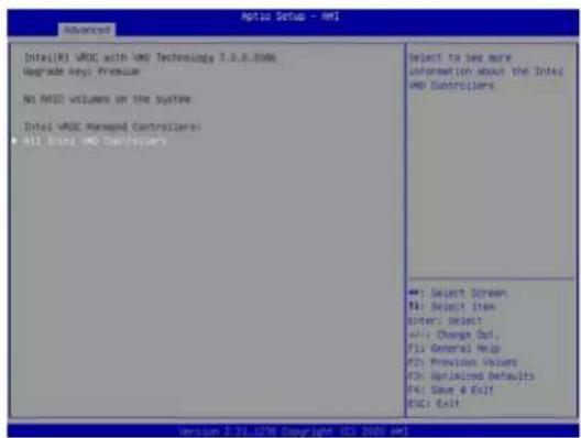
text_image
Advanced Intel(R) VHD with VHD Technology 3.0.8.2006 Upgrade Any: Premium No RMS volumes on the system Intel VHD Managed Controllers All Intel VHD Controllers Select to see more information about the Intel VHD Controllers Select Screen File Select Item Enter Select Add Change Out. Fill General Help FDS: Previous Values FDS: Optimized Defaults FDS: Save & Exit ESC: ExitFigure 6-2. BIOS VMD Setting Examples
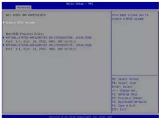
text_image
All Intel VMD Controllers ■ Create VMD volume Non-MAD: Physical Disker ■ HYDHALITATCH-AMR12MBV/SS ENL172M181E579F, 10246.5508 Port 110, Slot 25, CPU3, VMD, BDF 10:100.0 ■ HYDHALITATCH-AMR12MBV/SS ENL172M181E579F, 10246.5508 Port 111, Slot 21, CPU3, VMD, BDF 10:100.0 This page allows you to create a VMD volume ++ Select Screen F4: Select Item Enter: Select +/- Change Out. F1: General Hold F2: Previous Values F3: Optimized Defaults F4: Save & Exit G3C: Exit Version 2.25.1278 Copyright 101 2020 AM- Select Strip Size (Default 64KB).
- Select Create Volume.
- If another RAID is needed, start again at step 6.
- Press [F4] to save and reboot.

text_image
ADDI4 Setup + AMD Advanced Create RAID Volume Name: Volumes HOLD LEVEL: [MOSO/Strain] Enable RAID spersed over AMD ControlSelect1 Select Disk: HOLD/LERTICH-AMPS2NDY/ES SN:17291015708, 10246.5508 Part 1/0 CPU: AMD HOLD/LERTICH-AMPS2NDY/ES SN:17291015708, 10246.5508 Part 1/1 CPU: AMD Strip Size: [100x3] Capacity (KB): 29468.42 Create Volume X - to Select Disk →1 Select Screen F1: Select Item Enter: Select +/- Change Dot. F1: General Help F2: Precious Values F3: Optimized Defaults F4: Save & Exit ESC: ExitFigure 6-3. Created Volume without enabling RAID spanned over VMD Controller
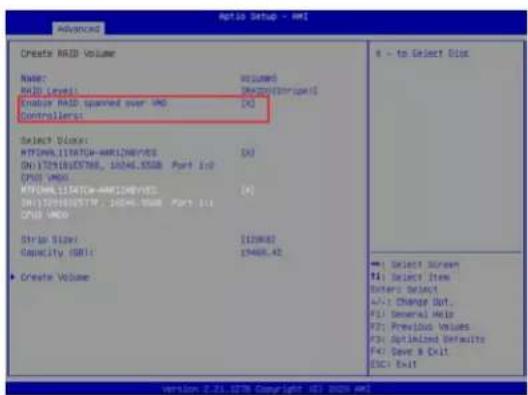
text_image
Auto Setup - MRI Advanced Create RAID Volume Name: RIO Level: Enable RAID spared over UNI Controllers: Select Blocks: MTP2011LITATION-AMR12NEVES ON I7325102788, 1604.355GB Port Ind CPU2 UNIQ MTP2011LITATION-AMR12NEVES ON I7325102788, 1604.355GB Port Ind CPU2 UNIQ Strip Size: 1129463 Capacity (GB): 19468.42 ■ Create Volume s - to Select Disk ■ Select Screen F1: Select Item Enter: Select F2: Change Out... F3: Several HxE F4: Previous Values F5: Optimized Defaults F6: Save & Exit ESC: ExitFigure 6-4. Created Volume with enabling RAID spanned over VMD Controller
Status Indications
An LED indicator on the drive carrier shows the RAID status of the drive.
| Drive Carrier Status LED Indicator | |
| Status State (red) | |
| Normal function Off | |
| Locating Blinking at | 4 Hz |
| Fault Solid on | |
| Rebuilding Blinking | at 1 Hz |
IBPI SFF 8489 Defined Status LED States
Hot Swap Drives
Intel VMD enables hot-plug and hot-unplug for NVMe SSDs, whether from Intel or other manufacturers. Under vSphere ESXi, several steps are necessary to avoid potential stability issues. See the information at link [1] below.
Hot-unplug
- Prevent devices from being re-detected during rescan:
esxcli storage core claiming autoclaim --enabled=false
- Unmount the VMFS volumes on the device. Check [2] for details.
- Detach the device. Check [3] for details.
- Physically remove the device.
Hot-plug
• Physically install the device.
ESXi will automatically discover NVMe SSDs, but a manual scan may be required in some cases.
Related Information Links
[1] https://kb.vmware.com/s/article/2151404
[2] https://docs.vmware.com/en/VMware-vSphere/6.5/com.vmware.vsphere.storage.doc/GUID-1B56EF97-F60E-4F21-82A7-8F2A7294604D.html
[3] https://docs.vmware.com/en/VMware-vSphere/6.5/com.vmware.vsphere.storage.doc/GUID-F2E75F67-740B-4406-9F0C-A2D99A698F2A.html
Chapter 7
Troubleshooting and Support
7.1 Information Resources
Website
A great deal of information is available on the Supermicro website, supermicro.com.

text_image
SUPERMICRO TECHNOLOGY & OUR PLANET Supermicro Resource-Saving Systems: Reduce Cost and Environmental ImpactFigure 7-1. Supermicro Website
- Specifications for servers and other hardware are available by clicking the menu icon, then selecting the Products option.
- The Support option offers downloads (manuals, BIOS/BMC, drivers, etc.), FAQs, RMA, warranty, and other service extensions.
Direct Links for the SYS-211GT-HNTR/HNC8R System
SYS-211GT-HNTR and SYS-211GT-HNC8R specifications pages
X13SET-G and X13SET-GC web pages for links to the Quick Reference Guide, User Manual, validated storage drives, etc.
Direct Links for General Support and Information
Frequently Asked Questions
Add-on card descriptions
TPM User Guide
General Memory Configuration Guide: X13
SuperDoctor5 Large Deployment Guide
Direct Links (continued)
For validated memory, see our Product Resources page
Product Matrices page for links to tables summarizing specs for systems, motherboards, power supplies, riser cards, add-on cards, etc.
Security Center for recent security notices
Supermicro Phone and Addresses
7.2 Baseboard Management Controller Interface
The system supports the Baseboard Management interface. BMC is used to provide remote access, monitoring and management. There are several BIOS settings that are related to BMC.
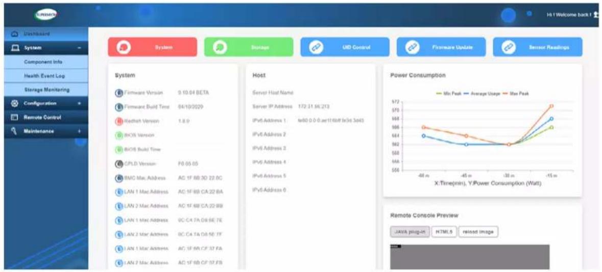
text_image
System Storage UID Control Firmware Update Sensor Readings Component Info Health Event Log Storage Monitoring Configuration Remote Control Maintenance System Firmware Version 9.10.04 BETA Firmware Build Time 04/10/2029 Redfish Version 1.8.9 BIO6 Version BIO6 Build Time CPLD Version F0.05.05 BMC Mac Address AC: 1F BB 3D 22.0C LAN 1 Mac Address AC: 1F BB CA:22.BA LAN 2 Mac Address AC: 1F BB CA:22.BB LAN 1 Mac Address GC-C4 TA DS-SE 7E LAN 2 Mac Address GC-C4 TA DS-SE 7F LAN 1 Mac Address AC: 1F BB CF:37 FA LAN 2 Mac Address AC: 1F BB CF:37.FB Host Server Host Name Server IP Address 172 31 SE 213 IPv6 Address 1 fe80 0.0.0.aer11f80ff le3rd 3o45 IPv6 Address 2 IPv6 Address 2 IPv6 Address 4 IPv6 Address 5 IPv6 Address 6 Power Consumption Max Peak Average Usage Max Peak X:Time(min), Y:Power Consumption (Watt) Remote Console Preview JAVA plug-in HTML.5 reload imageFigure 7-2. BMC Sample
7.3 Troubleshooting Procedures
Use the following procedures to troubleshoot your system. If you have followed all of the procedures below and still need assistance, refer to the Technical Support Procedures or Returning Merchandise for Service section(s) in this chapter. Power down the system before changing any non hot-swap hardware components.
No Power
- Make sure that there are no short circuits between the motherboard and the chassis.
- Make sure that the power connectors are properly connected.
- Check that the 115V/230 V switch, if available, on the power supply is properly set.
- Turn the power switch on and off to test the system, if applicable.
- Check the CPU socket for bent pins and make sure the CPU is fully seated.
- The battery on your motherboard may be old. Check to verify that it still supplies approximately 3 VDC. If it does not, replace it with a new one.
No Video
If the power is on but you have no video, remove all the add-on cards and cables. Then power up the system again to see if you then have video.
System Boot Failure
If the system does not display POST (Power-On-Self-Test) or does not respond after the power is turned on, check the following:
Turn on the system with only one DIMM module installed. If the system boots, check for bad DIMM modules or slots by following the Memory Errors Troubleshooting procedure below.
Memory Errors
- Make sure that the DIMM modules are properly and fully installed.
- Confirm that you are using the correct memory. Also, it is recommended that you use the same memory type and speed for all DIMMs in the system. See Section 3.3 for memory details.
- Check for bad DIMM modules or slots by swapping modules between slots and noting the results.
- Check the power supply voltage 115/230 V switch.
Losing the System's Setup Configuration
- Always replace power supplies with the exact same model that came with the system. A poor quality power supply may cause the system to lose the CMOS setup configuration.
- The battery on your motherboard may be old. Check to verify that it still supplies approximately 3 VDC. If it does not, replace it with a new one.
- If the above steps do not fix the setup configuration problem, contact your vendor for repairs.
When the System Becomes Unstable
If the system becomes unstable during or after OS installation, check the following:
- CPU/BIOS support: Make sure that your CPU is supported and that you have the latest BIOS installed in your system.
- Memory support: Make sure that the memory modules are supported by testing the modules using memtest86 or a similar utility.
Note: Refer to the product page on our website at http://www.supermicro.com for memory and CPU support and updates.
- HDD support: Make sure that all storage drives work properly. Replace the bad drives with good ones.
- System cooling: Check the system cooling to make sure that all heatsink fans and CPU/system fans, etc., work properly. Check the hardware monitoring settings in the BMC to make sure that the CPU and system temperatures are within the normal range. Also check the front panel Overheat LED and make sure that it is not on.
- Adequate power supply: Make sure that the power supply provides adequate power to the system. Make sure that all power connectors are connected. Please refer to our website for more information on the minimum power requirements.
- Proper software support: Make sure that the correct drivers are used.
If the system becomes unstable before or during OS installation, check the following:
- Source of installation: Make sure that the devices used for installation are working properly, including boot devices such as CD.
- Cable connection: Check to make sure that all cables are connected and working properly.
- Using the minimum configuration for troubleshooting: Remove all unnecessary components (starting with add-on cards first), and use the minimum configuration (but with a CPU and a memory module installed) to identify the trouble areas. Refer to the steps listed in Section A above for proper troubleshooting procedures.
- Identifying bad components by isolating them: If necessary, remove a component in question from the chassis, and test it in isolation to make sure that it works properly. Replace a bad component with a good one.
- Check and change one component at a time instead of changing several items at the same time. This will help isolate and identify the problem.
- To find out if a component is good, swap this component with a new one to see if the system will work properly. If so, then the old component is bad. You can also install the component in question in another system. If the new system works, the component is good and the old system has problems.
7.4 Crash Dump Using BMC
In the event of a processor internal error (IERR) that crashes your system, you may want to provide information to support staff. You can download a crash dump of status information using BMC.
Check BMC Error Log
- Access the BMC web interface.
- Click the Server Health tab, then Event Log to verify an IERR error.
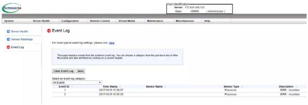
text_image
Host Identification Server: 172 831 049 125 User: ADMIN (Administrator) System Server Health Configuration Remote Control Virtual Media Maintenance Miscellaneous Help Server Health Sensor Readings Event Log Event Log For more special event log settings, please click here This page displays events from the system's event log. You can choose a category from the pull-down box to filter the events and also sort them by clicking on a column header. Clear Event Log Save Select an event log category: All Events Event ID : Time Stamp Sensor Name : Sensor Type : Description : 1 2017/10/19 15.38.37 Processor IERR - Assertion 2 2017/10/19 15.59.20 Processor IERR - AssertionFigure 7-4. BMC Event Log
In the event of an IERR, the BMC executes a crash dump. You must download the crash dump and save it.
7.5 UEFI BIOS Recovery
Warning: Do not upgrade the BIOS unless your system has a BIOS-related issue. Flashing the wrong BIOS can cause irreparable damage to the system. In no event shall Supermicro be liable for direct, indirect, special, incidental, or consequential damages arising from a BIOS update. If you do update the BIOS, do not shut down or reset the system while the BIOS is updating to avoid possible boot failure.
Overview
The Unified Extensible Firmware Interface (UEFI) provides a software-based interface between the operating system and the platform firmware in the pre-boot environment. The UEFI specification supports an architecture-independent mechanism that will allow the UEFI OS loader stored in an add-on card to boot the system. The UEFI offers clean, hands-off management to a computer during system boot.
Recovering the UEFI BIOS Image
A UEFI BIOS flash chip consists of a recovery BIOS block and a main BIOS block (a main BIOS image). The recovery block contains critical BIOS codes, including memory detection and recovery codes for the user to flash a healthy BIOS image if the original main BIOS image is corrupted. When the system power is turned on, the recovery block codes execute first. Once this process is complete, the main BIOS code will continue with system initialization and the remaining POST (Power-On Self-Test) routines.
Note 1: Follow the BIOS recovery instructions below for BIOS recovery when the main BIOS block crashes.
Note 2: When the BIOS recovery block crashes, you will need to follow the procedures to make a Returned Merchandise Authorization (RMA) request. Also, you may use the Supermicro Update Manager (SUM) Out-of-Band (https://www.supermicro.com.tw/products/nfo/SMS_SUM.cfm) to reflash the BIOS.
Recovering the Main BIOS Block with a USB Device
This feature allows the user to recover the main BIOS image using a USB-attached device without additional utilities used. A USB flash device such as a USB Flash Drive, or a USB CD/DVD ROM/RW device can be used for this purpose. However, a USB storage drive cannot be used for BIOS recovery at this time.
The file system supported by the recovery block is FAT (including FAT12, FAT16, and FAT32) which is installed on a bootable or non-bootable USB-attached device. However, the BIOS might need several minutes to locate the SUPER.ROM file if the media size becomes too large due to the huge volumes of folders and files stored in the device.
To perform UEFI BIOS recovery using a USB-attached device, follow the instructions below.
- Using a different machine, copy the "Super.ROM" binary image file into the Root "\" directory of a USB device or a writable CD/DVD.
Note 1: If you cannot locate the "Super.ROM" file in your drive disk, visit our website at www.supermicro.com to download the BIOS package. Extract the BIOS binary image into a USB flash device and rename it "Super.ROM" for the BIOS recovery use.
Note 2: Before recovering the main BIOS image, confirm that the "Super.ROM" binary image file you download is the same version or a close version meant for your motherboard. - Insert the USB device that contains the new BIOS image ("Super.ROM") into your USB drive and reset the system when the following screen appears.
- After locating the healthy BIOS binary image, the system will enter the BIOS Recovery menu as shown below.

text_image
SUPERIOR BMC IP:10.132.161.13 PEI--Could Not Find Recovery Image... 87Note: At this point, you may decide if you want to start the BIOS recovery. If you decide to proceed with BIOS recovery, follow the procedures below.

text_image
Aptia Setup Utility - Copyright (C) 2017 American Megatrends, Inc. Main Advanced Event Logs XML Recovery Security Book Save & Exit Please select blocks you want to update Book Number [Download] Boot Block update [Enabled] ► Proceed with flash update Set this option to reset NVRAM to default values +: Select Screen F1: Select items Enter: Select +/-: Change Opt. F1: General Help F2: Previous Values FS: Optimized Defaults F4: Save & Exit ESC: Exit Version 2.18.1266. Copyright (C) 2017 American Megatrends, Inc.- When the screen as shown above displays, use the arrow keys to select the item "Proceed with flash update" and press the
key. You will see the BIOS recovery progress as shown in the screen below.
Note: Do not interrupt the BIOS flashing process until it has completed.
- After the BIOS recovery process is complete, press any key to reboot the system.
- Using a different system, extract the BIOS package into a USB flash drive.
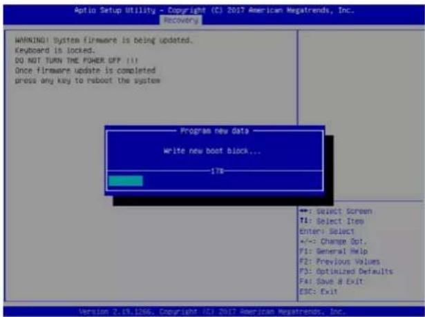
text_image
Optio Setup Utility - Copyright (C) 2017 American Megatrends, Inc. Recovery WARNING!! System firmware is being updated. Keyboard is locked. DO NOT TURN THE POWER OFF !!! Once firmware update is completed press any key to reboot the system Program new data Write new boot block... 178 +: Select Screen Y1: Select Item enter: Select +/-: Change Opt. Y1: General Help F2: Previous Values F3: Optimized Defaults F4: Save & Exit ESC: Exit Version 2.19.1266. Copyright (C) 2017 American Megatrends, Inc.- Press
continuously during system boot to enter the BIOS Setup utility. From the top of the tool bar, select Boot to enter the submenu. From the submenu list, select Boot
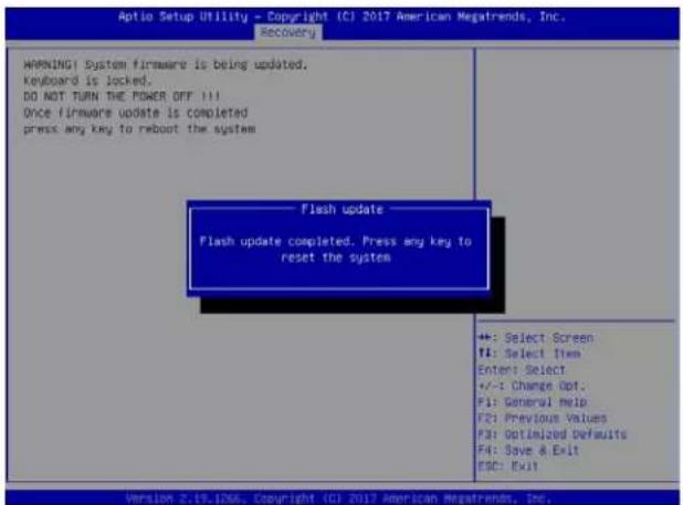
text_image
Optio Setup Utility - Copyright (C) 2017 American Megatrends, Inc. Recovery WARNING System firmware is being updated. Keyboard is locked. DO NOT TURN THE POWER OFF !!! Once firmware update is completed press any key to reboot the system Flash update Flash update completed. Press any key to reset the system +: Select Screen F1: Select Item Enter: Select +/-: Change Opt. F1: General Help F2: Previous Values F3: Optimized Defaults F4: Save & Exit ESC: Exit Version 2.19.1NSG. Copyright (C) 2017 American Megatrends, Inc.Option #1 as shown below. Then, set Boot Option #1 to [UEFI AP:UEFI: Built-in EFI Shell]. Press
- When the UEFI Shell prompt appears, type fs# to change the device directory path. Go to the directory that contains the BIOS package you extracted earlier from Step 6. Enter flash.nsh BIOSname.### at the prompt to start the BIOS update process.

text_image
Boot Configuration Boot mode select LEGACY to EFI support [DOUBLE] [Disabled] FIXED BOOT ORDER PRIORITIES Boot Option #1 Boot Option #2 Boot Option #3 Boot Option #4 Boot Option #5 Boot Option #6 Boot Option #7 Boot Option #8 Boot Option #9 Boot Option #10 Boot Option #11 Boot Option #12 Boot Option #13 Boot Option #14 Boot Option #15 Boot Option #16 Boot Option #17 Add New Boot Option [UEFI: AFCI: NoI...] [CO/DVD] [USB Hard Disk] [USB CD/DVD] [USB Key:SamDisk] [USB Floccyl] [USB Lxn] [Network:IDA GE 61...] [UEFI Hard Disk] [UEFI CD/DVD] [UEFI USB Hard Disk] [UEFI USB CD/DVD] [UEFI USB Key:UEFI...] [UEFI USB Floppy] [UEFI USB Lxn] [UEFI Networks] [Hard Disk] Sets the system boot order +: Select Screen F1: Select Item Enter: Select +/-: Change Opt. F1: General Help F2: Previous Values F3: Optimized Defaults F4: Save & Exit ESC: Exit Version 2.19.106, Copyright ICT 2017 American Megatrends, Inc.Note: Do not interrupt this process until the BIOS flashing is complete.
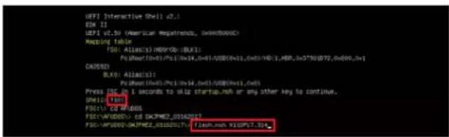
text_image
UFS1 Interactive Shell v2.1 DXH 21 UFS1 v2.50 (American Repathence, x04050000) Mapping TABLE FDS: ALLIAX(1) HKEYD: (UK3): Po:USX(1)H1/PCE(1)x14,0x81/USB(0x11,x6x11)HD(1,MBP,x07*90E72,0x600,x1) CAUSEN: BLKB: ALLIAX(1) Po:USX(1)PCE(1)x14,0x81/USB(0x11,x6x11) Press ESC to 1 seconds to xlg startup.nah or any other key to continue. Shell: (FDS) FDS: USX PUELS FDS: WYUDDO: (d) SKPMZ_0162017 FDS: WYUDDO: SKPMZ_0162017; fissn.nah x2SPV7.30- The screen above indicates that the BIOS update process is complete. When you see the screen above, unplug the AC power cable from the power supply, clear CMOS, and plug

text_image
Done. [ Access DOS Port Ex ] Read Index (xS1: xS0) Done. ********************************************************************** * - Program BIOS and ME (including P37) regions... **********************************************************************EMT Firmware update utility v5-49-91.1817
Copyright (C)2017 American Regatrends Inc. All Rights Reserved. CHILD = NAME Reading Flash ....... done - ME Data Line checking . OK - F/S checksum ....... OR - Check RowLayout ....... OK Eraving Boot Block ....... done Updating Boot block ....... done Verifying Boot Block ....... done Eraving Main Block ....... 040132000 (RR)the AC power cable in the power supply again to power on the system.
- Press
continuously to enter the BIOS Setup utility.
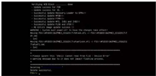
text_image
Verifying HCB Block ....../... done - Update success for FCM - Update success for SE. - Successful update Recovery Loader to QPMx!! - Successful update PWM((-) - Successful update PWM((-) - Successful update MFS, IWSI and JW021) - Successful update FLOD and JTOX((-) - ME Entire Image update success!! WARNING: System must power-off to have the changes take effect! Moving FSO::AF10005/04JPME2_03162017.txt+64_eff -> FSO::AF10005/04JPME2_03162017.txt RT.smc [+]? Moving FSO::AF10005/04JPME2_03162017.txt+FSO::AF10005/04JPME2_03162017.txt Parvuri.smc [+]? ********************************************************************** * Please ignore this "Shell" cannot press from file - device timer * warning message due to it does not impact fragmentation process. ********************************************************************** * Deleting * Delete successful. FDO: **********************************************************************-
Press
to load the default settings. -
After loading the default settings, press
to save the settings and exit the BIOS Setup utility.
7.6 CMOS Clear
JBT1 is used to clear CMOS, which will also clear any passwords. Instead of pins, this jumper consists of contact pads to prevent accidentally clearing the contents of CMOS.
To Clear CMOS
- First power down the system completely.
- Remove the cover of the chassis to access the motherboard.
- Remove the onboard battery from the motherboard.
- Short the CMOS pads with a metal object such as a small screwdriver for at least four seconds.
- Remove the screwdriver or shorting device.
- Replace the cover, reconnect the power cords and power on the system.
Notes: Clearing CMOS will also clear all passwords.
Do not use the PW_ON connector to clear CMOS.

JBT1 contact pads
7.7 Where to Get Replacement Components
If you need replacement parts for your system, to ensure the highest level of professional service and technical support, purchase exclusively from our Supermicro Authorized Distributors/System Integrators/Resellers. A list can be found at: http://www.supermicro.com. Click the "Where to Buy" tab.
7.8 Reporting an Issue
Technical Support Procedures
Before contacting Technical Support, please take the following steps. If your system was purchased through a distributor or reseller, please contact them for troubleshooting services. They have the best knowledge of your specific system configuration.
- Please review the Troubleshooting Procedures in this manual and Frequently Asked Questions on our website before contacting Technical Support.
- BIOS upgrades can be downloaded from our website. Note: Not all BIOS can be flashed depending on the modifications to the boot block code.
-
If you still cannot resolve the problem, include the following information when contacting us for technical support:
-
System, motherboard, and chassis model numbers and PCB revision number
- BIOS release date/version (this can be seen on the initial display when your system first boots up)
- System configuration
An example of a Technical Support form is posted on our website. Distributors: For immediate assistance, please have your account number ready when contacting our technical support department by email.
Returning Merchandise for Service
A receipt or copy of your invoice marked with the date of purchase is required before any warranty service will be rendered. You can obtain service by calling your vendor for a Returned Merchandise Authorization (RMA) number. When returning to the manufacturer, the RMA number should be prominently displayed on the outside of the shipping carton, and mailed prepaid or hand-carried. Shipping and handling charges will be applied for all orders that must be mailed when service is complete.
For faster service, RMA authorizations may be requested online (http://www.supermicro.com/support/rma/).
Whenever possible, repack the chassis in the original Supermicro carton, using the original packaging material. If these are no longer available, be sure to pack the chassis securely, using packaging material to surround the chassis so that it does not shift within the carton and become damaged during shipping.
This warranty only covers normal consumer use and does not cover damages incurred in shipping or from failure due to the alteration, misuse, abuse or improper maintenance of products.
During the warranty period, contact your distributor first for any product problems.
Vendor Support Filing System
For issues related to Intel, use the Intel IPS filing system:
https://www.intel.com/content/www/us/en/design/support/ips/training/welcome.html
For issues related to Red Hat Enterprise Linux, since it is a subscription based OS, contact your account representative.
7.9 Feedback
Supermicro values your feedback as we strive to improve our customer experience in all facets of our business. Please email us at techwriterteam@supermicro.com to provide feedback on our manuals.
7.10 Contacting Supermicro
Headquarters
Address: Super Micro Computer, Inc.
980 Rock Ave.
San Jose, CA 95131 U.S.A.
Tel: +1 (408) 503-8000
Fax: +1 (408) 503-8008
Email: marketing@supermicro.com (General Information)
Sales-USA@supermicro.com (Sales Inquiries)
Government_Sales-USA@supermicro.com (Gov. Sales Inquiries)
support@supermicro.com (Technical Support)
RMA@supermicro.com (RMA Support)
Webmaster@supermicro.com (Webmaster)
Website: www.supermicro.com
Europe
Address: Super Micro Computer B.V.
's-Hertogenbosch, The Netherlands
Tel: +31 (0) 73-6400390
Fax: +31 (0) 73-6416525
Email: Sales_Europe@supermicro.com (Sales Inquiries)
Support_Europe@supermicro.com (Technical Support)
RMA_Europe@supermicro.com (RMA Support)
Website: www.supermicro.nl
Asia-Pacific
Address: Super Micro Computer, Inc.
3F, No. 150, Jian 1st Rd.
Zhonghe Dist., New Taipei City 235
Taiwan (R.O.C)
Tel: +886-(2) 8226-3990
Fax: +886-(2) 8226-3992
Email: Sales-Asia@supermicro.com.tw (Sales Inquiries)
Support@supermicro.com.tw (Technical Support)
RMA@supermicro.com.tw (RMA Support)
Website: www.supermicro.com.tw
Appendix A
Standardized Warning Statements for AC Systems
About Standardized Warning Statements
The following statements are industry standard warnings, provided to warn the user of situations which have the potential for bodily injury. Should you have questions or experience difficulty, contact Supermicro's Technical Support department for assistance. Only certified technicians should attempt to install or configure components.
Read this appendix in its entirety before installing or configuring components in the Supermicro chassis.
These warnings may also be found on our website at http://www.supermicro.com/about/policies/safety_information.cfm.
Warning Definition

Warning! This warning symbol means danger. You are in a situation that could cause bodily injury. Before you work on any equipment, be aware of the hazards involved with electrical circuitry and be familiar with standard practices for preventing accidents.
警告の定義
この警告サインは危険を意味します。
Installation Instructions

Warning! Read the installation instructions before connecting the system to the power source.
設置手順書
Warning! This product relies on the building's installation for short-circuit (overcurrent) protection. Ensure that the protective device is rated not greater than: 250 V, 20 A.
サーキット・ブレーカー
Power Disconnection Warning

Warning! The system must be disconnected from all sources of power and the power cord removed from the power supply module(s) before accessing the chassis interior to install or remove system components (except for hot-swap components).

text_image
CAUTION: This unit has redundant power sources. Please disconnect all the power cords before servicing.電源切断の警告
Equipment Installation

Warning! Only authorized personnel and qualified service persons should be allowed to install, replace, or service this equipment.
機器の設置
Warning! This unit is intended for installation in restricted access areas. A restricted access area can be accessed only through the use of a special tool, lock and key, or other means of security. (This warning does not apply to workstations).
アクセス制限区域
Warning! There is the danger of explosion if the battery is replaced incorrectly. Replace the battery only with the same or equivalent type recommended by the manufacturer. Dispose of used batteries according to the manufacturer's instructions
電池の取り扱い
Redundant Power Supplies

Warning! This unit might have more than one power supply connection. All connections must be removed to de-energize the unit.
冗長電源装置
Warning! Hazardous voltage or energy is present on the backplane when the system is operating. Use caution when servicing.
バックプレーンの電圧
Comply with Local and National Electrical Codes
Warning! Installation of the equipment must comply with local and national electrical codes.
地方および国の電気規格に準拠
Warning! Ultimate disposal of this product should be handled according to all national laws and regulations.
製品の廃棄
Warning! Hazardous moving parts. Keep away from moving fan blades. The fans might still be turning when you remove the fan assembly from the chassis. Keep fingers, screwdrivers, and other objects away from the openings in the fan assembly's housing.
ファンの警告
Power Cable and AC Adapter

Warning! When installing the product, use the provided or designated connection cables, power cables and AC adaptors. Using any other cables and adaptors could cause a malfunction or a fire. Electrical Appliance and Material Safety Law prohibits the use of UL or CSA-certified cables (that have UL/CSA shown on the cord) for any other electrical devices than products designated by Supermicro only.
電源コードとACアダプター
System Specifications
Processor Support\*
Single 4th Generation Intel Xeon Scalable Processor in a Socket E (LGA 4677)
Chipset\*
Intel C741 PCH
BIOS\*
256 Mb SPI AMI® BIOS
Memory\*
Up to 4 TB of ECC RDIMM and RDIMM 3DS DDR5 memory with speeds of up to 4800 MT/s
Storage Drives\*
Front hot-swap drives:
Supports up to four SATA/SAS/NVMe drives depending on selected enablement kits (SAS with SYS-211GT-HNC8R only)
M.2 drives:
Two M.2 in 2280 (PCIe 5.0 x4 & SATA)
Motherboard\*
SYS-211GT-HNTRL X13SET-G; 12.42" x 8.53" (315.5 x 216.7 mm)
SYS-211GT-HNC8R: X13SET-GC; 12.42" x 8.53" (315.5 x 216.7 mm)
Chassis
CSE-GT214BC-R2K21BP; 2U rackmount, 17.67 x 3.46 x 28 in. (449 x 87.9 x 711.2 mm)
System Cooling
Two 80-mm mid chassis fans per system, one fan integrated inside the power supply; one CPU heatsink per node, one CPU air shroud per node
Dummy Tray
MCP-120-21405-0N
To avoid overheating, please ensure a dummy tray is inserted into any unused drive bays.
Power Supply
Model: PWS-2K21A-BR, 2200 W redundant module, 80Plus Titanium level
AC Input Voltages: 100-240 VAC
Rated Input Current:
1200 W: 100-127 VAC
1800 W: 200-220 VAC
1980 W: 220-230 VAC
2090 W: 230-240 VAC (TUV/CB)
2200 W: 220-240 VAC (WL/cUL only)
2090 W: 180-220 VAC (UL/cUL only)
2090 W: 230-240 VDC (CCC only)
Rated Input Frequency: 50-60 Hz
Rated Output Power: +12 V
Max: 100 A / Min: 0 A (100-127 VAC)
Max: 150 A / Min: 0 A (200-220 VAC)
Max: 165 A / Min: 0 A (220-230 VAC)
Max: 174.17 A / Min: 0 A (230-240 VAC)
Max: 174.17 A / Min: 0 A (180-220 VAC, UL/cUL only)
Max: 183.33 A / Min: 0 A (220-240 VAC, UL/cUL only)
Max: 174.17 A / Min: 0 A (230-240 VDC, CCC only)
Standby +12 Vsb: Max: 2.1 A / Min: 0 A
*per node
Operating Environment
Operating Temperature: 10° to 35° C (50° to 95° F)
Non-operating Temperature: -30° to 60° C (-22° to 140° F)
Operating Relative Humidity: 8% to 80% (non-condensing)
Non-operating Relative Humidity: 8% to 90% (non-condensing)
Regulatory Compliance
FCC, ICES, CE, VCCI, RCM, NRTL, CB, UKCA
Applied Directives, Standards
Electromagnetic Compatibility Regulations 2016
FCC Part 15
ICES-003
VCCI-CISPR 32
AS/NZS CISPR 32
BS/EN 55032
BS/EN 55035
CISPR 32
CISPR 35
BS/EN 61000-3-2
BS/EN 61000-3-3
BS/EN 61000-4-2
BS/EN 61000-4-3
BS/EN 61000-4-4
BS/EN 61000-4-5
BS/EN 61000-4-6
BS/EN 61000-4-8
BS/EN 61000-4-11
Product Safety: 2014/35/EU (LVD Directive)
UL/CSA 62368-1 (USA and Canada)
Electrical Equipment (Safety) Regulations 2016
IEC/BS/EN 62368-1
Environment:
2011/65/EU (RoHS Directive)
EC 1907/2006 (REACH)
2012/19/EU (WEEE Directive)
Warning! This product can expose you to chemicals including lead, known to the State of California to cause cancer and birth defects or other reproductive harm. For more information, go to www.P65Warnings.ca.gov
Perchlorate Warning
California Best Management Practices Regulations for Perchlorate Materials: This Perchlorate warning applies only to products containing CR (Manganese Dioxide) Lithium coin cells. Perchlorate Material-special handling may apply. See www.dtsc.ca.gov/hazardouswaste/perchlorate