LXSK1315 - Mounting kit American International - Free user manual and instructions
Find the device manual for free LXSK1315 American International in PDF.

User questions about LXSK1315 American International
0 question about this device. Answer the ones you know or ask your own.
Ask a new question about this device
Download the instructions for your Mounting kit in PDF format for free! Find your manual LXSK1315 - American International and take your electronic device back in hand. On this page are published all the documents necessary for the use of your device. LXSK1315 by American International.
USER MANUAL LXSK1315 American International
natural_image
Exploded view diagram of electronic device modules and connectors (no text or labels)VEHICLE APPLICATIONS
Lexus
1998-05 GS 300 (w/out Factory Navigation)
1998-03 GS 400
2001-05 GS 430
LXSK1315 Mounting Kit
DASH DISASSEMBLY INSTRUCTIONS
- Carefully unsnap and pull forward the vent/clock assembly from above the factory radio.
- Unplug the wire harnesses from the rear of the vent/clock assembly and remove assembly.
- Remove the (2) 10mm bolts securing the upper radio/climate control brackets to the sub-dash.
- Carefully remove the ashtray assembly from below the climate controls.
- Remove the (2) 10mm bolts securing the lower radio/climate control brackets to the sub-dash.
- Carefully pull radio/climate control assembly forward, disconnect all wire harnesses and antenna lead wire from radio and climate controls and remove entire assembly.
- Remove the factory climate control unit from the factory brackets.
KIT ASSEMBLY INSTRUCTIONS
Single DIN Mount Applications
- Attach the left and right side brackets to the main bracket.
- Insert pocket into lower section of the main bracket.
- Attach left and right side brackets to the rear of the pocket using screws supplied.
- Insert DIN sleeve from your new radio into the upper section of the installation kit.
- Depress the tabs from inside the sleeves opening upward, outward, and downward to secure sleeve to the installation kit.
- Install radio into sleeve and lock into place.
- Attach a rear support bracket to the rear of the new radio and adjust as necessary to attach to the rear support stud located on the back of the pocket using the small phillips screw supplied with kit.

natural_image
Technical line drawing of a mechanical assembly with two rectangular components and internal brackets (no text or symbols)KIT ASSEMBLY INSTRUCTIONS
Single ISO Mount Applications
- Attach the left and right side brackets to the main bracket.
- Insert pocket into lower section of the main bracket.
- Attach left and right side brackets to the rear of the pocket using screws supplied.
- Attach climate controls to the top of the kit using factory screws.
- Attach (1) ISO Spacer to the inside of upper section on both Left & Right mounting brackets as shown in Fig. A.
- Insert ISO mountable radio between ISO mount brackets and loosely attach to sides of radio using screws provided with radio when possible or hardware included with kit.
- Slide radio components forward or backward for desired look and tighten screws.
- Attach a rear support bracket to the rear of the new radio and adjust as necessary to attach to the rear support stud located on the back of the pocket using the small phillips screw supplied with kit.
NOTE: ISO trim ring (ITR-1315) may be used in place of after-market radio's trim rings.
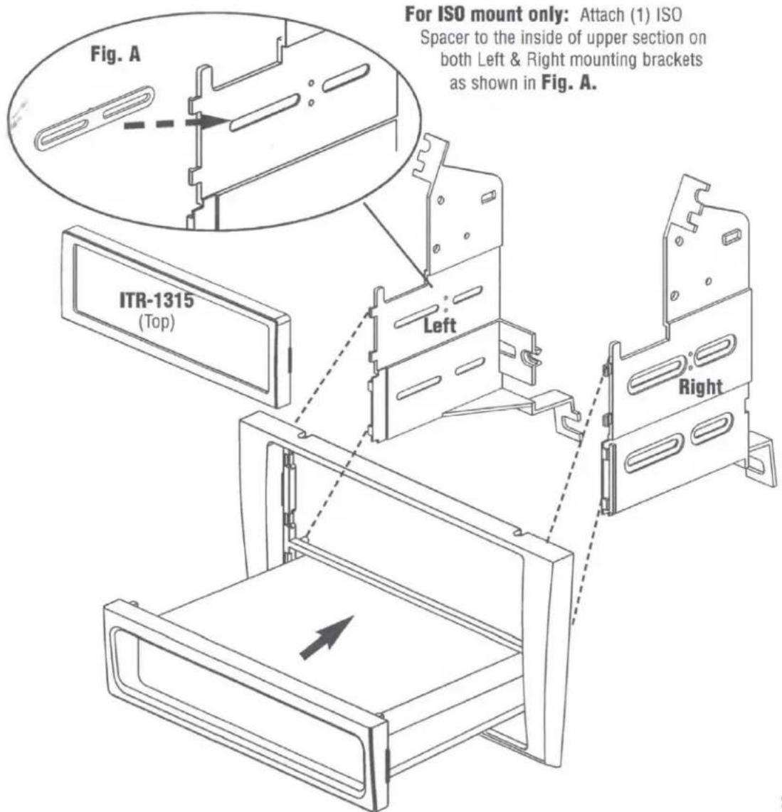
text_image
Fig. A For ISO mount only: Attach (1) ISO Spacer to the inside of upper section on both Left & Right mounting brackets as shown in Fig. A. ITR-1315 (Top) Left RightKIT ASSEMBLY INSTRUCTIONS
Double DIN Mount Applications
- Remove the Shaded tab from the bottom of each left and right mounting bracket (see Fig. B below).
- Cut and remove center rib from main bracket.
- Attach the left and right side brackets to the main bracket.
- Attach climate controls to the top of the kit using factory screws.
- Follow steps 5-7 from single ISO instructions on page 3.
- Attach a rear support bracket to the rear of the radio components and adjust as needed to allow rear support bracket to rest in the sub-dash.
NOTE: ISO trim ring (DITR-1315) must be used in place of after-market radio's trim rings. For ISO mount applications, mount after-market radio components to side brackets using screws provided with radio when possible or hardware included with kit optional.
