PDU20B2F10R - Inverter CyberPower - Free user manual and instructions
Find the device manual for free PDU20B2F10R CyberPower in PDF.

User questions about PDU20B2F10R CyberPower
0 question about this device. Answer the ones you know or ask your own.
Ask a new question about this device
Download the instructions for your Inverter in PDF format for free! Find your manual PDU20B2F10R - CyberPower and take your electronic device back in hand. On this page are published all the documents necessary for the use of your device. PDU20B2F10R by CyberPower.
USER MANUAL PDU20B2F10R CyberPower
Reliability. Quality. Value.
User Manual
Power
Distribution
Unit
CyberPower®
Reliability. Quality. Value.
4241 12th Ave E #400,
Shakopee, MN 55379
1-877-297-6937
www.CPSww.com
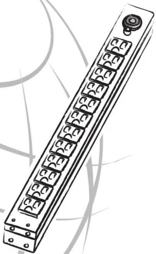
natural_image
Illustration of a vertical electronic component with multiple slots and a button, no text or symbols present.Table of Contents
Model List ....1
PDU Naming Convention ....1
Package Contents ...... 2
Safety Precautions 2
Installation 3
Horizontal Installation 3
Vertical Installation with Brackets ... 4
Vertical Installation -
Keyhole Mounts (0U models only) ... 5
Cord Retention Tray installation ..... 5
Meter Configuration 5
Electrical Installation 6
Troubleshooting 6
Product Features
Technical Specification ....7
Basic Series 7
Metered Series 9
Basic Series (0U) 10
Metered Series (0U) 11
Warranty & Service 12
Model List:
Basic Series:
| PDU15B8R | PDU20B8R | PDU20BT8R |
| PDU15B10R | PDU20B10R | PDU20BT10R |
| PDU15B12R | PDU20B12R | PDU20BT12R |
| PDU15B2F8R | PDU20B2F8R | PDU20BT2F8R |
| PDU15B2F10R | PDU20B2F10R | PDU20BT2F10R |
| PDU15B2F12R | PDU20B2F12R | PDU20BT2F12R |
| PDU15B4F8R | PDU20B4F8R | PDU20BT4F8R |
| PDU15B4F10R | PDU20B4F10R | PDU20BT4F10R |
| PDU15B4F12R | PDU20B4F12R | PDU20BT4F12R |
| PDU15B6F8R | PDU20B6F8R | PDU20BT6F8R |
| PDU15B6F10R | PDU20B6F10R | PDU20BT6F10R |
| PDU15B6F12R | PDU20B6F12R | PDU20BT6F12R |
Metered Series:
| PDU15M2F8R | PDU20M2F8R | PDU20MT2F8R |
| PDU15M2F10R | PDU20M2F10R | PDU20MT2F10R |
| PDU15M2F12R | PDU20M2F12R | PDU20MT2F12R |
Basic Series (0U):
| PDU15BV14F | PDU20BV14F | PDU20BVT14F |
| PDU15BV16F | PDU20BV16F | PDU20BVT16F |
| PDU15BV20F | PDU20BV20F | PDU20BVT20F |
| PDU15BV28F | PDU20BV28F | PDU20BVT28F |
| PDU15BV32F | PDU20BV32F | PDU20BVT32F |
Metered Series (0U):
| PDU15MV20F | PDU20MV20F | PDU20MVT20F |
| PDU15MV26F | PDU20MV26F | PDU20MVT26F |
| PDU15MV32F | PDU20MV32F | PDU20MVT32F |
PDU Naming Convention:

- Amperage: Amperage - 15A, 20A, 30A
- Series: B: =Basic M: =Metered
SW: = Switched - Rack Space: NULL: =Horizontal V:= Vertical
- Input Voltage: NULL: =120V HV: = High Voltage - 200V to 230V
- Plug Type: NULL: =NEMA 5-15P / 5-20P
T: = Twist (NEMA L5-L6 Plug)
IEC:= (IEC C14/C20) - Outlet Number Front Number of Outlets followed by F - Example 8F
- Outlet Number Rear Number of Outlets followed by R - Example 8R
- Network Management NET
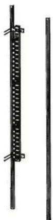
Package Contents
PDU (1)
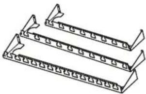
natural_image
Technical line drawing of three parallel metal plate structures with rivets (no text or symbols)Cord Retention Tray
(1/2/3/4 pcs - varies by model)
Mounting Brackets


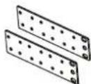
Used (1 set) Vertical Installation Vertical Mounting Brackets (1 set)
Used (1 set) (for 0U models only)
Horizontal Installation

Bracket Mounting
Screws M4 X 8 (4pcs)

Cord Retention Tray
Mounting Screws M3 X 6
(4/8/12/16 pcs - varies by model)


Keyhole Mounting Pegs (2pcs)
with Screws M4 X 8 (2pcs)
(for 0U models only)

Cord Retainer Clips (8/10/12/14/16/
20/24/30/32/38 pcs - varies by model)
for Cord Retention Tray

Ground Screw M4 X 6 (1 pcs)
Documentation:

User Manual

Product Registration Card

Check
Before using, please check to ensure the package contains all the
items shown above. If there are missing parts please contact
CyberPower technical support at www.CPSww.com or call 1-877-297-6937.
Safety Precautions - Read the following before installing or operating the Power Distribution Unit (PDU):
- Use only the supplied hardware to attach the mounting brackets.
- The PDU must only be plugged into a three-wire, grounded outlet on a circuit protected by a fuse or circuit breaker. Connection to any other type of power outlet may result in a shock hazard.
- Do not use extension cords or adapters with this PDU.
- Never install a PDU, or associated wiring or equipment, during a lightning storm.
- Check that the power cord, plug, and socket are in good condition.
- CAUTION! To prevent the risk of fire or electric shock, this PDU should be installed in a temperature and humidity controlled indoor area free of conductive contaminants. Do not install this PDU where excessive moisture or heat is present..
Installation
Horizontal Installation (1U models only)
Step 1 – Mounting bracket installation
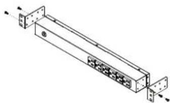
natural_image
Technical line drawing of a mechanical or electronic assembly with mounting flanges and connectors (no text or symbols)Install the screws (M4 X 8) in holes diagonal from each other.
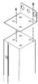
Step 2 – PDU Mounting

natural_image
Technical line drawing of a mechanical assembly with vertical posts and mounting holes (no text or symbols)Install the PDU using fasteners compatible with the rack.
Vertical Installation with Brackets
Step 1 – Mounting bracket installation
Install the screws (M4 X 8) in holes diagonal from each other.
Step 2 – PDU Mounting
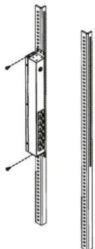
natural_image
Technical line drawing of a vertical metal frame assembly with mounting holes and internal components (no text or symbols)Install the PDU using fasteners compatible with the rack.
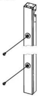
Vertical Installation with Brackets (0U models only)
Step 1 – Mounting bracket installation

Attach the Vertical Mounting Brackets to the PDU with the 4 supplied Bracket Mounting Screws (M4 X 8).
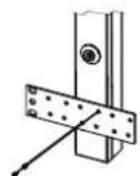
Step 2 – PDU Mounting
natural_image
Two vertical metal bars with bolt holes, no text or symbols presentInstall the PDU using fasteners compatible with the rack.
For information on Cyberpower products, visit www.CPSww.com
Vertical Installation with Keyhole Mounts (0U Models) Electrical Installation
Step 1 – Keyhole Mount installation
natural_image
Technical line drawing of two mechanical components with pin connectors (no text or symbols)Attach the Keyhole Mounting Pegs to the PDU with the 2 supplied Bracket Mounting Screws (M4 X 8).
Step 2 – PDU Mounting
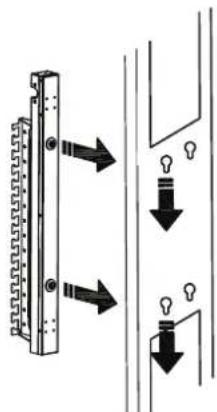
text_image
Diagram showing light bulb installation on a wall-mounted device with directional arrows indicating movement or flow.Align the the Keyhole Mounts to the Keyhole Slots on the rack. Insert and slide down to lock firmly into place.
Cord Retention Tray installation (Optional for both horizontal and vertical installations)
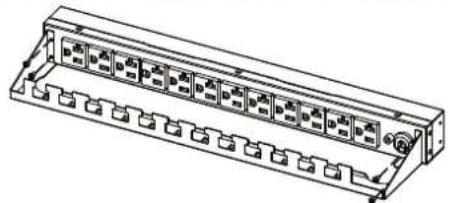
natural_image
Technical line drawing of a multi-pin electrical connector housing (no text or symbols)Attach the Cord Retention Tray to the PDU with the 4 supplied Cord Retention Tray Mounting Screws (M3 X 6).

text_image
My Mounting Screws (MS X 6).Attach the Cord Retainer Clips to the Cord Retention Tray.
Meter Configuration

Depending on installation method (vertical or horizontal), the LED Meter may need to be rotated, before installation, for proper orientation.
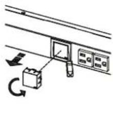
natural_image
Simple line drawing of a mechanical or electrical component with a box and rotating arrow (no text or symbols)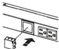
Use a screwdriver to gently remove the LED Meter. Rotate the LED Meter 90 degrees, and insert back into the PDU.
Step 1 – Receptacle evaluation
Ensure that the plug type of your PDU unit (e.g. NEMA 5-15P, NEMA 5-20P, NEMA L5-30P) matches the wall receptacle type that you are using.

PDU must be plugged into a three-wire, grounded wall receptacle only. The wall receptacle must also be connected to an appropriate branch circuit/main with fuse or circuit breaker protection. Connection to any other type of wall receptacle may result in a shock hazard.
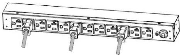
Step 2 – Plug the PDU into the wall receptacle

natural_image
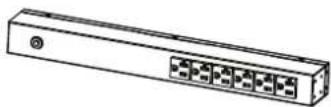
Diagram of a rack-mounted server unit with multiple ports and a cable connecting to a terminal outlet (no text or labels)Step 3 – Attach equipment
Before attaching equipment, it is important to calculate the total load that you will be placing on the PDU. It is extremely important not to exceed the PDU's maximum current load (as outlined in the Specifications section). In order to determine your total load, simply add up the amperage of your devices and ensure that it does not exceed the unit's capacity.
natural_image
Line drawing of a rectangular electronic device with multiple ports and connectors (no text or symbols)Troubleshooting
| Problem Possible Cause Solution | ||
| PDU Outlets do not provide power to connected equipment | 1. Open breaker2. Loose power cord | Reset Breaker check if plug is completely connected.If the problem remains contact tech support. |
| Amperage displayed on Amperage Meter exceeds the unit's capability (Metered type only) | 1. Overload2. Amperage meter is damaged | The meter will flash when overloaded.Reduce the load on the PDU until the overload is gone.If the problem remains contact tech support. |
| Circuit breaker has tripped | 1. Sustained overload2. Excessive ambient or internal temperatures.3. Faulty breaker | Reset Breaker.If the problem remains contact tech support. |
Basic Series Basic Series
Product Features
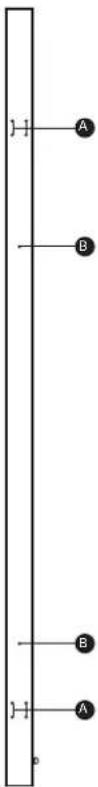
Front View
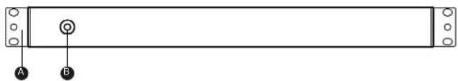
natural_image
Simple line drawing of a rectangular object with two labeled points A and B, no text or symbols present.A. Mounting Bracket
B. Circuit Breaker
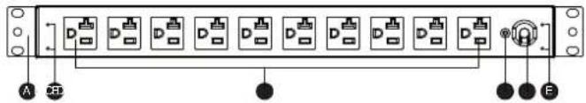
Back View
text_image
A B C D EA. Mounting Bracket
B. Rear Outlets
C. External Site Ground
D. AC Power Cord
E. Cord Retention Tray
Screw Holes
Technical Specifications Technical Specifications
| Model Name | PDU15B8RPDU15B10RPDU15B12R | PDU20B8RPDU20B10RPDU20B12R | PDU20BT8RPDU20BT10RPDU20BT12R |
| Input | |||
| Voltage | 100 ~ 125 V | ||
| Max current | 15 A | 20 A | |
| Circuit Breaker 15 A | 20 A | ||
| Plug Type NEMA 5-15P NEMA 5-20P NEMA L5-20P | |||
| Power Cord Length | 15 ft | ||
| Output | |||
| Voltage | 100 ~ 125 V | ||
| Current 15 A | 20 A | ||
| Outlet Type | NEMA 5-15R | NEMA 5-20R | |
| Indicators | |||
| LED Indicators | N/A | ||
| Meter Readout | N/A | ||
| Physical | |||
| Dimension (WxDxH) | 17.5" x 1.5" x 1.75" / 44.5 x 3.81 x 4.45 cm | ||
| Environmental | |||
| Humidity | Operating 0 to 95% Non-condensingNon-Operating 0 to 95% Non-condensing | ||
| Altitude | Operating 0ft to 10,000ftNon-Operating 0ft to 50,000ft | ||
| Temperature | Operating 32F to 95FNon-Operating 5F to 113F | ||
| Safety Approvals | |||
| Certifications | ETL (test followed UL 1363)RoHS | ||
| Warranty | Lifetime | ||
Product Features
Front View

text_image
A B CA. Mounting Bracket
B. Circuit Breaker
C. Front Outlets
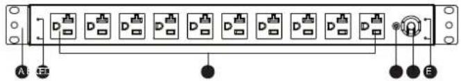
Back View
text_image
A B CA. Mounting Bracket
B. Rear Outlets
C. External Site Ground
D. AC Power Cord
E. Cord Retention Tray
Screw Holes
| Model Name | PDU15B2F8RPDU15B2F10RPDU15B2F12RPDU15B4F8RPDU15B4F10RPDU15B4F12RPDU15B6F8RPDU15B6F10RPDU15B6F12R | PDU20B2F8RPDU20B2F10RPDU20B2F12RPDU20B4F8RPDU20B4F10RPDU20B4F12RPDU20B6F8RPDU20B6F10RPDU20B6F12R | PDU20BT2F8RPDU20BT2F10RPDU20BT2F12RPDU20BT4F8RPDU20BT4F10RPDU20BT4F12RPDU20BT6F8RPDU20BT6F10RPDU20BT6F12R |
| Input | |||
| Voltage | 100 ~ 125 V | ||
| Max current | 15 A | 20 A | |
| Circuit Breake | 15 A | 20 A | |
| Plug Type NEMA 5-15P NEMA 5-20P NE | MA L5-20P | ||
| Power Cord Length | 15 ft | ||
| Output | |||
| Voltage | 100 - 125 V | ||
| Current 15 A | 20 A | ||
| Outlet Type | NEMA 5-15R | NEMA 5-20R | |
| Indicators | |||
| LED Indicators | N/A | ||
| Meter Readout | N/A | ||
| Physical | |||
| Dimension (WxDxH) | 17.5" x 2.25" x 1.75" / 44.5 x 5.72 x 4.45 cm | ||
| Environmental | |||
| Humidity | Operating 0 to 95% Non-condensingNon-Operating 0 to 95% Non-condensing | ||
| Altitude | Operating 0ft to 10,000ftNon-Operating 0ft to 50,000ft | ||
| Temperature | Operating 32F to 95FNon-Operating 5F to 113F | ||
| Safety Approvals | |||
| Certifications | ETL (test followed UL 1363)RoHS | ||
| Warranty | Lifetime | ||
Metered Series
Product Features
Front View

text_image
A B C DA. Mounting Bracket
B. Circuit Breaker
C. LED Meter Readout
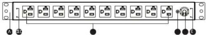
Back View
text_image
A B C D EA. Mounting Bracket
B. Rear Outlets
C. External Site Ground
D. AC Power Cord
E. Cord Retention Tray Screw Holes
Technical Specifications
| Model Name | PDU15M2F8RPDU15M2F10RPDU15M2F12R | PDU20M2F8RPDU20M2F10RPDU20M2F12R | PDU20MT2F8RPDU20MT2F10RPDU20MT2F12R |
| Input | |||
| Voltage | 100 ~ 125 V | ||
| Max Current 15 A | 20 A | ||
| Circuit Breaker 15 A | 20 A | ||
| Plug Type NEMA 5-15P NEMA 5-20P NEMA L5-20P | |||
| Power Cord Length | 15 ft | ||
| Output | |||
| Voltage | 100 ~ 125 V | ||
| Current | 15 A | 20 A | |
| Outlet Type | NEMA 5-15R | NEMA 5-20R | |
| Fitters & Protection | |||
| EMI/RFI Filtration | N/A | ||
| Surge Suppression | N/A | ||
| Indicators | |||
| LED Indicators | N/A | ||
| Meter Readout | Amperage | ||
| Physical | |||
| Dimension (WxDxH) | 17.5" x 2.25" x 1.75" / 44.5 x 5.72 x 4.45 cm | ||
| Environmental | |||
| Humidity | Operating 0 to 95% Non-condensingNon-Operating 0 to 95% Non-condensing | ||
| Altitude | Operating 0ft to 10,000ftNon-Operating 0ft to 50,000ft | ||
| Temperature | Operating 32F to 95FNon-Operating 5F to 113F | ||
| Safety Approvals | |||
| Certifications | ETL (test followed UL 1363)RoHS | ||
| Warranty | Lifetime | ||
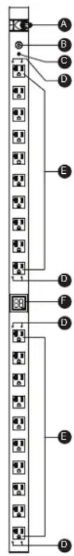
Basic Series (0U)
Product Features
Front View Back View
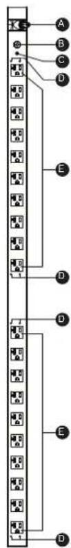
text_image
A B C D E D D E DA. AC Power Cord
B. Circuit Breaker
C. External Site Ground
D. Cord Retention Tray
Screw Holes
E. Front Outlets
text_image
1-1 A B B A pA. Bracket Screw Hole
B. Keyhole Mount Peg Screw Holes
Technical Specifications
| Model Name | PDU15BV14FPDU15BV16FPDU15BV20FPDU15BV28FPDU15BV32F | PDU20BV14FPDU20BV16FPDU20BV20FPDU20BV28FPDU20BV32F | PDU20BVT14FPDU20BVT16FPDU20BVT20FPDU20BVT28FPDU20BVT32F |
| Input | |||
| Voltage | 100 ~ 125 V | ||
| Max Current 15 A | 20 A | ||
| Circuit Breaker 15 A | 20 A | ||
| Plug Type NEMA 5-15P NEMA 5-20P NE | MA L5-20P | ||
| Power Cord Length | 10 ft | ||
| Output | |||
| Voltage | 100 ~ 125 V | ||
| Current | 15 A | 20 A | |
| Outlet Type | NEMA 5-15R | NEMA 5-20R | |
| Indicators | |||
| LED Indicators | N/A | ||
| Meter Readout | N/A | ||
| Physical | |||
| Dimension (WxDxH) | 1.75" x 1.5" x 24" / 4.45 x 3.81 x 60.96 cm1.75" x 1.5" x 36" / 4.45 x 3.81 x 91.44 cm1.75" x 1.5" x 48" / 4.45 x 3.81 x 121.92 cm1.75" x 1.5" x 60" / 4.45 x 3.81 x 152.40 cm1.75" x 1.5" x 70" / 4.45 x 3.81 x 177.80 cm | ||
| Environmental | |||
| Humidity | Operating 0 to 95% Non-condensingNon-Operating 0 to 95% Non-condensing | ||
| Altitude | Operating 0ft to 10,000ftNon-Operating 0ft to 50,000ft | ||
| Temperature | Operating 32F to 95FNon-Operating 5F to 113F | ||
| Safety Approvals | |||
| Certifications | ETL (test followed UL 1363)RoHS | ||
| Warranty | Lifetime | ||
Metered Series (0U)
Product Features
Front View
text_image
A B C D E F D E DBack View
A. AC Power Cord
B. Circuit Breaker
C. External Site Ground
D. Cord Tray Screws Holes
E. Front Outlets
B. Keyhole Mount Peg Screw Holes

text_image
A B B ATechnical Specifications
| Model Name | PDU15MV20FPDU15MV26FPDU15MV32F | PDU20MV20FPDU20MV26FPDU20MV32F | PDU20MTV20FPDU20MTV26FPDU20MTV32F |
| Input | |||
| Voltage | 100 ~ 125 V | ||
| Max Current 15 A | 20 A | ||
| Circuit Breaker 15 A | 20 A | ||
| Plug Type NEMA 5-15P NEMA 5-20P NEMA L5-20P | |||
| Power Cord Length | 10 ft | ||
| Output | |||
| Voltage | 100 ~ 125 V | ||
| Current 15 A | 20 A | ||
| Outlet Type NEMA 5-15R | NEMA 5-20R | ||
| Indicators | |||
| LED Indicators | N/A | ||
| Meter Readout | Amperage | ||
| Physical | |||
| Dimension (WxDxH) | 1.75" x 2.25" x 48" / 4.45 x 5.72 x 121.92 cm1.75" x 2.25" x 60" / 4.45 x 5.72 x 152.40 cm1.75" x 2.25" x 70" / 4.45 x 5.72 x 177.80 cm | ||
| Environmental | |||
| Humidity | Operating 0 to 95% Non-condensingNon-Operating 0 to 95% Non-condensing | ||
| Altitude | Operating 0ft to 10,000ftNon-Operating 0ft to 50,000ft | ||
| Temperature | Operating 32F to 95FNon-Operating 5F to 113F | ||
| Safety Approvals | |||
| Certifications | ETL (test followed UL 1363)RoHS | ||
| Warranty | Lifetime | ||
Product Registration
Thank you for purchasing a CyberPower product. Prompt product registration entitles coverage under the Limited Warranty, and also allows the opportunity to be notified of product enhancements, upgrades, and other announcements.
Registration is quick and easy at www.cpsww.com/register.
Need Additional Help?
Feel free to contact our Tech Support department with installation, troubleshooting, or general product questions.
CyberPower Technical Support
Phone: 1-877-297-6937
Email: tech@cpsww.com
Web: www.CPSwv
Mail: 4241 12th Avenue E, Suite 400 Shakopee, MN 55379
Hours of Operation: Monday – Friday, 8:00am – 5:00pm (CST)
Limited Warranty
Read the following terms and conditions carefully before using the CyberPower PDU(the "Product"). By using the Product you consent to be bound by and become a party to the terms and conditions of this Limited Warranty (together referred to as this "Warranty"). If you do not agree to the terms and conditions of this Warranty, you should return the Product for a full refund prior to using it.
Who is Providing this Warranty?
CyberPower Systems (USA), Inc. ("CyberPower") provides this Limited Warranty.
What Does This Warranty Cover?
This warranty covers defects in materials and workmanship in the Product under normal use and conditions.
What is the Period of Coverage?
This Warranty is for as long as the original owner owns the Product.
Who Is Covered?
This warranty only covers the original purchaser.
Coverage ends if you sell or otherwise transfer the Product.
How Do You Get Service?
- Call us at (877) 297-6937 or write to us at Cyber Power Systems (USA), Inc., 4241 12th Ave. E., STE 400, Shakopee, MN 55379 or send us an e-mail message at claims@cyberpowersystems.com for instructions.
- When you contact CyberPower, identify the Product, the Purchase Date, and the item(s) of Connected Equipment. Have information on all applicable insurance or other resources of recovery/payment that are available to the Initial Customer and Request a Claim Number.
- You must provide a purchase receipt (or other proof of the original purchase) and provide a description of the defect.
- Pack and ship the product to CyberPower and, if requested, the item(s) of Connected Equipment, a repair cost estimate for the damage to the Connected Equipment, and all claim forms that CyberPower provides to you. Show the Claim Number on the shipping label or include it with the product. You must prepay all shipping costs, you are responsible for packaging and shipment, and you must pay the cost of the repair estimate.
What Will We Do To Correct Problems?
CyberPower will inspect and examine the Product.
If the Product is defective in material or workmanship, CyberPower will repair or replace it at CyberPower's expense, or, if CyberPower is unable to or decides not to repair or replace the Product (if defective) within a reasonable time, CyberPower will refund to you the full purchase price you paid for the Product (purchase receipt showing price paid is required).
Who Pays For Shipping?
We pay when we send items to you; you pay when you send items to us.
What Are Some Things This Warranty Does Not Cover?
- This Warranty does not cover any software that was damaged or needs to be replaced due to the failure of the Product or any data that is lost as a result of the failure or the restoration of data or records, or the reinstallation of software.
- This Warranty does not cover or apply to: misuse, modification, operation or storage outside environmental limits of the Product or the equipment connected to it, nor for damage while in transit or in storage, nor if there has been improper operation or maintenance, or use with items not designed or intended for use with the Product, such as laser printers, appliances, aquariums, medical or life support devices, etc.
What are the Limitations?
- This Warranty does not apply unless the Product and the equipment that was connected to it were connected to properly wired and grounded outlets (including compliance with electrical and safety codes of the most current electrical code), without the use of any adapters or other connectors.
- The Product must have been plugged directly into the power source and the equipment connected to the Product must be directly connected to the Product and not "daisy-chained" together in serial fashion with any extension cords, another Product or device similar to the Product, surge suppressor, or power tap. Any such installation voids the Limited Warranty.
- The Product and equipment connected to it must have been used properly in a suitable and proper environment and in conformance with any license, instruction manual, or warnings provided with the Product and the equipment connected to it.
- The Product must have been used at all times within the limitations on the Product's VA capacity.
- The sole and exclusive remedies of the Initial Customer are those provided by this Warranty.
Contact Information
CyberPower Systems, Inc.
4241 12th Ave. East
Suite 400
Shakopee, MN 55379
Phone: (952) 403-9500
Toll-free: (877) 297-6937
CyberPower is the warrantor under this Limited Warranty.
You may also contact CyberPower on the web at CPSww.com.