PowerMAX Tension PMT150HT2-E20 - Boîtier de mesure Elite Prime Vision - Free user manual and instructions
Find the device manual for free PowerMAX Tension PMT150HT2-E20 Elite Prime Vision in PDF.

User questions about PowerMAX Tension PMT150HT2-E20 Elite Prime Vision
0 question about this device. Answer the ones you know or ask your own.
Ask a new question about this device
Download the instructions for your Boîtier de mesure in PDF format for free! Find your manual PowerMAX Tension PMT150HT2-E20 - Elite Prime Vision and take your electronic device back in hand. On this page are published all the documents necessary for the use of your device. PowerMAX Tension PMT150HT2-E20 by Elite Prime Vision.
USER MANUAL PowerMAX Tension PMT150HT2-E20 Elite Prime Vision
text_image
EPV PROJECTION SCREENSElectric Motorized Projection Screen PowerMax Tension Series
User's Guide
Important Safety & Warning Precautions
Make sure to read this user's guide and follow the procedures below5
Caution: The screen's Black Top Drop is already set to its maximum drop distance. There is NO extra Black Top Drop in the roller. Please be aware of this as it will void your warranty with Elite Screens. Unapproved changes or modifications (except for cutting the power cord for hardwire installations) to this unit are prohibited and will void your warranty. For more information, please contact our Technical Support Department at (877) 511-1211 Ext. 604.
- Please retain this user's guide for future reference.
- To avoid damaging the unit, do not use with any unauthorized accessories not recommended by the manufacturer.
• +andle the unit carefully during transportation to avoid any damages. - To ensure safe and reliable operation, direct connection to a properly grounded power source is advised.
• The power outlet supplying power to the unit should be close to the unit and easily accessible. - Do not install the unit on uneven or inclined surfaces.
- Do not put heavy objects on the power cord and position it properly to avoid creating a trip obstacle.
- Never overload the power cord to prevent an electric shock or fire due to a loose contact or a short circuit.
- There are not user serviceable parts in this unit. Do not attempt to disassemble this unit by yourself. No one except authorized technicians can open and make repairs to this unit.
• Make sure the power source this unit is connected to has a continuous power flow. - 9f there is need to use an extension cord, make sure the cord has an equal rating as the appliance to avoid overheat.
- Do not handle the power plug when your hands are wet or your feet are in contact with water.
Do not use this unit under the following circumstances5
- Disconnect the power cord under the conditions of heavy rain, wind, thunder or lightning.
- Avoid direct Sunshine, rain shower and moisture.
- Keep away from fire sources and high temperature to prevent this device from overheating.
- Cut off the power supply first before transportation or maintenance.
- Fully disconnect from the power supply when the unit is not in use for a long period of time, as should be done with any other electric household appliance.
- To avoid possible injury and/or an electric shock, do not attempt to use the screen if there is obvious damage or if there are any evident broken parts.
WARN9NG
The Screen's Top Black Drop is already set to its maximum drop distance. There is NO extra top black drop in the roller. Please be aware of this as it will void the limitation of your warranty.
9 individual modifications to this product are prohibited and will void the warranty with the manufacturer. Please contact Elite Screens Customer Service for any questions.
NOTE"
This equipment has been tested and found to comply with the limits for a Class B digital device, pursuant to Part 85 of the FCC Rules.
These limits are designed to provide reasonable protection against harmful interference in a residential installation. This equipment generates and can radiate radio frequency energy and, if not installed and used in accordance with the instructions, may cause harmful interference to radio communications.
+however, there is no guarantee that the interference will not occur on a particular installation. 9f this equipment causes harmful interference to radio or television reception, which can be determined by turning the equipment off and on, the user is encouraged to try to correct the interference by one or more of the following measures.
√ Reorient or relocate the receiving antenna of the device which may be causing the interference5
√ Increase the separation between the screen and the device's receiver5
√ Connect the equipment into a different power outlet other than the device5
Pre-Installation
- Carefully unpack the screen.
- Always handle the screen in a leveled position on a clean surface.
- 9n order to protect the screen from exposure to stains, keep the screen out of contact with foreign particles such as dust, sawdust, and/or liquids.
NOTE
Regardless of the mounting method, the screen should be securely supported so that the vibration or pulling on the viewing surface will not cause the casing to become loose or fall. The installer must insure that the fasteners used are of adequate strength and suitable for the installation location.
Accessories for PowerMax Tension Series

IR remote

RF remote
natural_image
Simple line drawing of a coiled tube connected to a container with a sensor or device (no text or symbols)3 way wall switch
text_image
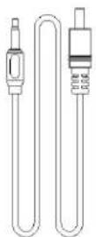
Red 12V Green 0V 5-12 volt trigger cable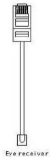
When using your IR remote, always be sure to point your remote at the IR receiver.
9n-wall RJ45 module
87V wireless trigger
text_image
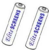
Elite SCREENS Elite SCREENS2 x AAA Batteries
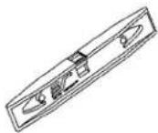
Bubble leveler
Hardware Parts List for PowerMax Tension Series
a.
b.
C.
d.
e.


| +ardware Parts List | QTY |
| a. Mounting Bracket | 7 |
| b. M4x50 Screw | 4 |
| c. M82 Anchor | 4 |
| d. Suspended Ceiling Bracket Connector | 7 |
| e. M5x86 Screw& Bolt | 4 |
Flush Mount to the Wall
- Mark the location of where the screen is to be installed, drill your holes and insert the M12Anchors (c).
- 9 install the Mounting Brackets (a) to the wall and secure with the M4x50 Screws (b).

text_image
Mounting Bracket Anchor Wall
text_image
Mounting bracket Fix Plate 8 M4x50 Screw Mounting Bracket Fix Plate 7Rev.880386-MZ 3 www.epvscreens.com
- Attach the screen to the Mounting Brackets (a) by inserting the top of the case to Fix Plate 8 and securing the back of the case to Fix Plate 7. Make sure the case slots are securely attached to the mounting brackets.

Flush Mount to the Ceiling
- Mark the location of where the screen is to be installed, drill your holes and insert the M12Anchors (c).
- 9 install the Mounting Brackets (a) to the ceiling and secure with the M4x50 Screws (b).

text_image
Ceiling M80 Anchor Mounting Bracket Mounting Bracket Fix Plate 8 M4x50 Screw Mounting Bracket Fix Plate 7- Attach the screen to the Mounting Bracket (a) by inserting the top of the case to Fix Plate 1 and securing the back of the case to Fix Plate 2. Make sure the case slots are securely attached to the Mounting Bracket (a).

text_image
Fix Plate 8 SPV
text_image
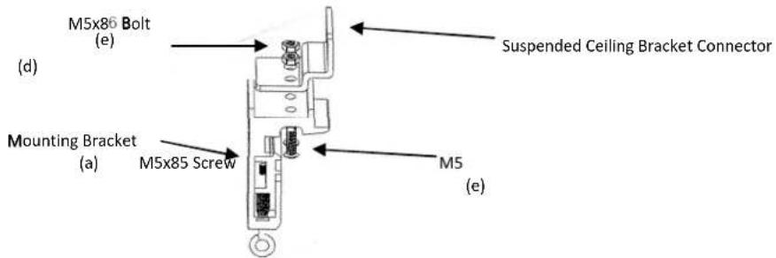
Fix Plate 7 BSVSuspended Ceiling using Chains (additional hardware required)
- You can also hang the screen on a ceiling by using chains (not included).
- Connect the Suspended Ceiling Bracket Connector (d) to the Mounting Bracket (a) and secure with the M5x16 Screws & Bolts (e).
text_image
M5x86 Bolt (e) Mounting Bracket (a) M5x85 Screw M5 (e) Suspended Ceiling Bracket Connector- 9insert chains (not included) through the loop holes of the Suspended Ceiling Bracket Connector (d).
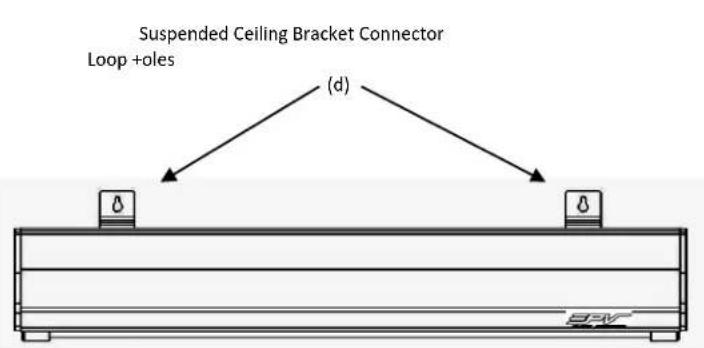
text_image
Suspended Ceiling Bracket Connector Loop +oles (d)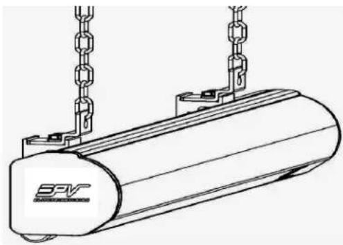
natural_image
Technical line drawing of a cylindrical mechanical component with hanging chains and a base (no text or symbols)Screen removal from the Mounting Brackets
- Pull down on the Mounting Bracket Release Tab and remove the bottom case away from the wall/ceiling followed by the top of the case.

text_image
3FVRelease Tab

text_image
Technical diagram showing a mechanical assembly with a vertical bar and a labeled component 'SFV' in an arrow.Pull bottom of case first away from wall/ceiling
Screen material tension adjustment (4mm Allen Wrench required and not included)
Remove the weight bar end cap to expose the adjustment tension knob. Insert your 4mm Allen Wrench to push in the adjustment tension knob, turn clockwise and your screen will gain more tension. Turn the Allen Wrench counter clockwise and the screen will lose tension. Please note this adjustment is not necessary as the tension of the screen has been set to its factory setting for best performance. Please contact Elite Screens for assistance to avoid damaging the screen and voiding your warranty at techsupport@elitescreens.com
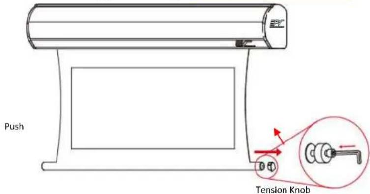
text_image
Push Tension KnobControl System for PowerMax Tension Series
3 Prong Power Cable
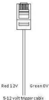
- 5-12V Trigger: The built-in 5-12V trigger input allows your screen to synchronize its drop & rise with the projector's power cycle. The screen deploys when the projector powers up and will retract when the projector powers down. The 5-12 volt adaptor connects to your projector's trigger output via a separate cable that may or may not be provided by the manufacturer of the projector. The trigger feature will not work without an output cable from the projector, but it can be tested by connecting the Red (+) and Green (-) cable to a 9-volt battery.

text_image
Red: DC 12 + Green: 0 V - gter Cable5-12 Volt Trigger Cable
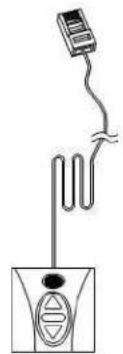
- 3-Way Wall Switch: The 3-way wall switch is a wall mount control box with an up/stop/down button and plugs directly into the screen's RJ-45 input.
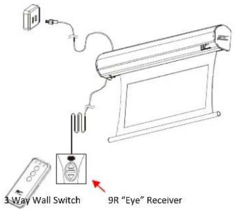
text_image
3 Way Wall Switch 9R "Eye" Receiver-
IR Remote Control: The 9nfrared functions by direct line of sight contact with a beam range of 30 feet.
-
IR "Eye" Receiver: The 9R "Eye" Receiver plugs directly into the screen's RJ-45 input to present a low profile line-of-sight control option for your 9R remote control even in a recessed ceiling installation.

text_image
Diagram showing a remote control device connected to a wall-mounted air conditioner unit, with a close-up of the device's internal structure.- RF Remote Control: The radio waves eliminate the need for a direct line of sight with a range of 800 feet.

flowchart
graph TD
    A["Device 1"] -->|UP| B["Device 2"]
    A -->|Stop| C["Device 3"]
    A -->|Down| D["Device 4"]
    B --> E["Device 5"]
    C --> F["Device 6"]
    D --> G["Device 7"]
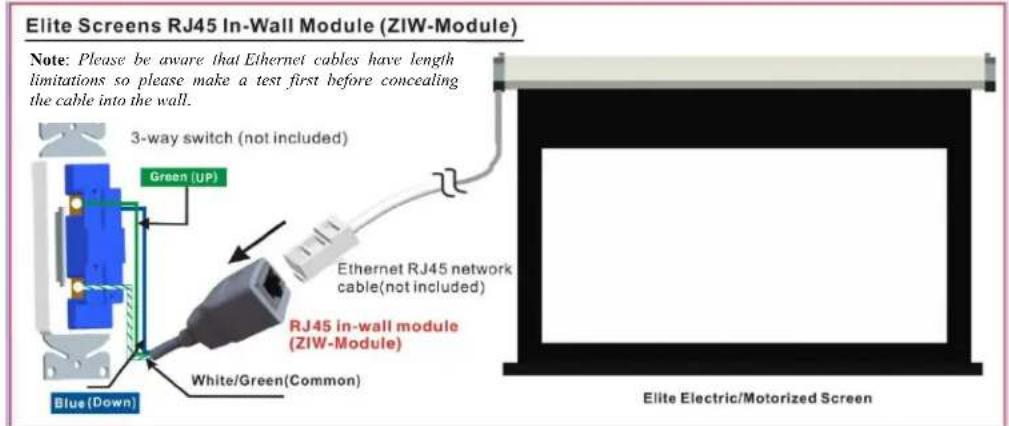
- In-wall RJ45 Module: The RJ45 module connects to a local wall switch for Up/Down control of your electric screen. Please follow the picture diagram below for instructions on how to connect this accessory.
text_image
Elite Screens RJ45 In-Wall Module (ZIW-Module) Note: Please be aware that Ethernet cables have length limitations so please make a test first before concealing the cable into the wall. 3-way switch (not included) Green (UP) Blue (Down) White/Green(Common) Ethernet RJ45 network cable(not included) RJ45 in-wall module (ZIW-Module) Elite Electric/Motorized ScreenSteps to attach Elite Screens Motorized Screen to your local wall switch
- Attach the in-wall module (Part #ZIW-Module) to your local wall switch as shown in diagram above
- Attach an RJ45 Ethernet cable (not included) to the ZIW-Module and the other end to the RJ45 input on your Elite electric screen.
- After testing the connection, place the in-wall switch module in/on the wall and wire the Ethernet cable into the wall and complete the setup.
For more information, technical support or your local Elite Screens contact, please visit www.elitescreens.com