RN1723 - Electronic component Microchip - Free user manual and instructions
Find the device manual for free RN1723 Microchip in PDF.

User questions about RN1723 Microchip
0 question about this device. Answer the ones you know or ask your own.
Ask a new question about this device
Download the instructions for your Electronic component in PDF format for free! Find your manual RN1723 - Microchip and take your electronic device back in hand. On this page are published all the documents necessary for the use of your device. RN1723 by Microchip.
USER MANUAL RN1723 Microchip
RN1723 Development Board User's Guide
Note the following details of the code protection feature on Microchip devices:
• Microchip products meet the specification contained in their particular Microchip Data Sheet.
- Microchip believes that its family of products is one of the most secure families of its kind on the market today, when used in the intended manner and under normal conditions.
- There are dishonest and possibly illegal methods used to breach the code protection feature. All of these methods, to our knowledge, require using the Microchip products in a manner outside the operating specifications contained in Microchip's Data Sheets. Most likely, the person doing so is engaged in theft of intellectual property.
• Microchip is willing to work with the customer who is concerned about the integrity of their code.
- Neither Microchip nor any other semiconductor manufacturer can guarantee the security of their code. Code protection does not mean that we are guaranteeing the product as "unbreakable."
Code protection is constantly evolving. We at Microchip are committed to continuously improving the code protection features of our products. Attempts to break Microchip's code protection feature may be a violation of the Digital Millennium Copyright Act. If such acts allow unauthorized access to your software or other copyrighted work, you may have a right to sue for relief under that Act.
Information contained in this publication regarding device applications and the like is provided only for your convenience and may be superseded by updates. It is your responsibility to ensure that your application meets with your specifications. MICROCHIP MAKES NO REPRESENTATIONS OR WARRANTIES OF ANY KIND WHETHER EXPRESS OR IMPLIED, WRITTEN OR ORAL, STATUTORY OR OTHERWISE, RELATED TO THE INFORMATION, INCLUDING BUT NOT LIMITED TO ITS CONDITION, QUALITY, PERFORMANCE, MERCHANTABILITY OR FITNESS FOR PURPOSE. Microchip disclaims all liability arising from this information and its use. Use of Microchip devices in life support and/or safety applications is entirely at the buyer's risk, and the buyer agrees to defend, indemnify and hold harmless Microchip from any and all damages, claims, suits, or expenses resulting from such use. No licenses are conveyed, implicitly or otherwise, under any Microchip intellectual property rights unless otherwise stated.
Trademarks
The Microchip name and logo, the Microchip logo, dsPIC, FlashFlex, flexPWR, JukeBlox, KEELOQ, KEELOQ logo, Kleer, LANCheck, MediaLB, MOST, MOST logo, MPLAB, OptoLyzer, PIC, PICSTART, PIC ^82 logo, RightTouch, SpyNIC, SST, SST Logo, SuperFlash and UNI/O are registered trademarks of Microchip Technology Incorporated in the U.S.A. and other countries.
The Embedded Control Solutions Company and mTouch are registered trademarks of Microchip Technology Incorporated in the U.S.A.
Analog-for-the-Digital Age, BodyCom, chipKIT, chipKIT logo, CodeGuard, dsPICDEM, dsPICDEM.net, ECAN, In-Circuit Serial Programming, ICSP, Inter-Chip Connectivity, KleerNet, KleerNet logo, MiWi, motorBench, MPASM, MPF, MPLAB Certified logo, MPLIB, MPLINK, MultiTRAK, NetDetach, Omniscient Code Generation, PICDEM, PICDEM.net, PICkit, PICtail, RightTouch logo, REAL ICE, SQL, Serial Quad I/O, Total Endurance, TSHARC, USBCheck, VariSense, ViewSpan, WiperLock, Wireless DNA, and ZENA are trademarks of Microchip Technology Incorporated in the U.S.A. and other countries.
SQTP is a service mark of Microchip Technology Incorporated in the U.S.A.
Silicon Storage Technology is a registered trademark of Microchip Technology Inc. in other countries.
GestIC is a registered trademark of Microchip Technology Germany II GmbH & Co. KG, a subsidiary of Microchip Technology Inc., in other countries.
All other trademarks mentioned herein are property of their respective companies.
© 2015, Microchip Technology Incorporated, Printed in the U.S.A., All Rights Reserved.
ISBN: 978-1-5224-0084-4
QUALITY MANAGEMENT SYSTEM
CERTIFIED BY DNV
$$ = = \text { ISO / TS } 1 6 9 4 9 = = $$
Microchip received ISO/TS-16949:2009 certification for its worldwide headquarters, design and wafer fabrication facilities in Chandler and Tempe, Arizona; Gresham, Oregon and design centers in California and India. The Company's quality system processes and procedures are for its PIC® MCUs and dsPIC® DSCs, KEELoo® code hopping devices, Serial EEPROMs, microperipherals, nonvolatile memory and analog products. In addition, Microchip's quality system for the design and manufacture of development systems is ISO 9001:2000 certified.
Object of Declaration: RN1723 Development Board
EU Declaration of Conformity
Manufacturer:
Microchip Technology Inc.
2355 W. Chandler Blvd.
Chandler, Arizona, 85224-6199
USA
This declaration of conformity is issued by the manufacturer.
The development/evaluation tool is designed to be used for research and development in a laboratory environment. This development/evaluation tool is not a Finished Appliance, nor is it intended for incorporation into Finished Appliances that are made commercially available as single functional units to end users under EU EMC Directive 2004/108/EC and as supported by the European Commission's Guide for the EMC Directive 2004/108/EC (8 ^th February 2010).
This development/evaluation tool complies with EU RoHS2 Directive 2011/65/EU.
This development/evaluation tool, when incorporating wireless and radio-telecom functionality, is in compliance with the essential requirement and other relevant provisions of the R&TTE Directive 1999/5/EC and the FCC rules as stated in the declaration of conformity provided in the module datasheet and the module product page available at www.microchip.com.
For information regarding the exclusive, limited warranties applicable to Microchip products, please see Microchip's standard terms and conditions of sale, which are printed on our sales documentation and available at www.microchip.com.
Signed for and on behalf of Microchip Technology Inc. at Chandler, Arizona, USA

text_image
Derek Carlson VP Development Tools
NOTES:
Table of Contents
Preface 7
Chapter 1. Introduction
1.1 Contents ...... 13
1.2 Functionality and Features ...... 13
Chapter 2. Hardware
2.1 Development Board Layout and Components 17
2.2 Hardware Features ...... 20
Chapter 3. Initial Development Board Configuration
3.1 Setting up the Python™ Server 24
3.2 Setting up The RN1723 Embedded Client 28
3.3 Sample Terminal Output 32
3.4 Advanced Settings 33
Appendix A. RN1723 Development Board Schematics
Worldwide Sales and Service 42
NOTES:
Preface
NOTICE TO CUSTOMERS
All documentation becomes dated, and this manual is no exception. Microchip tools and documentation are constantly evolving to meet customer needs, so some actual dialogs and/or tool descriptions may differ from those in this document. Please refer to our web site (www.microchip.com) to obtain the latest documentation available.
Documents are identified with a "DS" number. This number is located on the bottom of each page, in front of the page number. The numbering convention for the DS number is "DSXXXXXXXXA", where "XXXXXXXXX" is the document number and "A" is the revision level of the document.
For the most up-to-date information on development tools, see the MPLAB ^® IDE online help. Select the Help menu, and then Topics to open a list of available online help files.
INTRODUCTION
This chapter contains general information that will be useful to know before using the RN1723 Development Board. Items discussed in this chapter include:
- Document Layout
- Conventions Used in this Guide
• Recommended Reading
• The Microchip Web Site - Development Systems Customer Change Notification Service
- Customer Support
• Document Revision History
DOCUMENT LAYOUT
This document describes how to use the RN1723 Development Board as a development tool to emulate and debug firmware on a target board. This document includes the following chapters:
- Chapter 1. "Introduction" provides an overview of the RN1723 Development Board, highlighting its features and uses.
- Chapter 2. "Hardware" provides an overview of the RN1723 Development Board hardware components and features.
- Chapter 3. "Initial Development Board Configuration" provides information on configuring the development board for first-time use, including setting up a web server.
- Appendix A. "RN1723 Development Board Schematics" provides schematic diagram information for the development board.
CONVENTIONS USED IN THIS GUIDE
This manual uses the following documentation conventions:
DOCUMENTATION CONVENTIONS
| Description Represents Examples | ||
| Italic characters Referenced | books MPLAB | ^ IDE User's Guide |
| Emphasized text ...is the only compiler... | ||
| Initial caps A window the Output window | ||
| A dialog the Settings dialog | ||
| A menu selection select Enable Programmer | ||
| Quotes A field name in a window or dialog | "Save project before build" | |
| Underlined, italic text with right angle bracket | A menu path File > Save | ____ |
| Bold characters A dialog button Click OK | ||
| A tab | Click the Power tab | |
| Text in angle brackets <> | A key on the keyboard | Press,, |
| Plain Courier New | Sample source code | #define START |
| Filenames | autoexec.bat | |
| File paths | c:\mcc18\h | |
| Keywords | _asm, _endasm, static | |
| Command-line options | -Opa+, -Opa- | |
| Bit values | 0, 1 | |
| Constants | 0xFF, 'A' | |
| Italic Courier New | A variable argument | file.o, where file can be any valid filename |
| Square brackets [] | Optional arguments | mcc18 [options] file [options] |
| Curly brackets and pipe character: { | } | Choice of mutually exclusive arguments; an OR selection | errorlevel {0|1} |
| Ellipses... | Replaces repeated text | var_name [, var_name...] |
| Represents code supplied by user | void main (void){ ...} | |
| Notes | A Note presents information that we want to re-emphasize, either to help you avoid a common pitfall or to make you aware of operating differences between some device family members. A Note can be in a box, or when used in a table or figure, it is located at the bottom of the table or figure. | Note: This is a standard note box.CAUTIONThis is a caution note.Note 1: This is a note used in a table. |
RECOMMENDED READING
The following documents are recommended as supplemental reference resources.
RN1723 Family Data Sheet (DS70005224)
Consult this document for detailed information on the RN4020 Bluetooth ^® Low Energy Module. Reference information found in this data sheet includes:
• Device pinout and packaging details
• Device electrical specifications
- List of features included on the device
WiFi Command Reference Manual (DS50002230)
This reference manual provides information on the commands and features for Microchip products that utilize the WiFly radio module command set. The WiFly radio module is a complete, stand-alone embedded wireless LAN access device. The device has an on-board TCP/IP stack and applications, and in the simplest hardware configuration, requires only four pins: Power, TX, RX, and Ground.
RN131/RN171/RN1723 Evaluation Kits User's Guide (DS50002183)
This user's guide describes the RN evaluation boards that are used for demonstrating the capabilities of the RN131, RN171, and RN1723 modules. These RN evaluation boards have the flexibility to connect directly to a PC or laptop through a standard USB interface or to embedded controllers through the serial UART interface. Reference information in this user's guide includes:
- Overview of the evaluation kit hardware and evaluation board features and components
- Hardware and module configuration
- Sensor interfaces and push button functions
- Evaluation board schematics
PICDEM™ PIC18 Explorer Demonstration Board User's Guide (DS51721)
This document describes how to use the PICDEM PIC18 Explorer Demonstration Board as a development tool to emulate and debug firmware on a target board. Reference information found in this user's guide includes:
• Functionality and features
- Hardware features
• Development board schematics
Explorer 16 Development Board User's Guide (DS50001589)
This document describes how to use the Explorer 16 Development Board as a development tool to emulate and debug firmware on a target board. Reference information found in this user's guide includes:
• Functionality and features
- Hardware features
• Development board schematics
These documents are available for download from the Microchip website (www.microchip.com).
Microchip provides online support via our web site at: http://www.microchip.com. This web site makes files and information easily available to customers. Accessible by most Internet browsers, the web site contains the following information:
- Product Support – Data sheets and errata, application notes and sample programs, design resources, user's guides and hardware support documents, latest software releases and archived software
- General Technical Support – Frequently Asked Questions (FAQs), technical support requests, online discussion groups, Microchip consultant program member listings
- Business of Microchip – Product selector and ordering guides, latest Microchip press releases, listings of seminars and events; and listings of Microchip sales offices, distributors and factory representatives
DEVELOPMENT SYSTEMS CUSTOMER CHANGE NOTIFICATION SERVICE
Microchip's customer notification service helps keep customers current on Microchip products. Subscribers will receive e-mail notification whenever there are changes, updates, revisions or errata related to a specified product family or development tool of interest.
To register, access the Microchip web site at www.microchip.com, click on Customer Change Notification and follow the registration instructions.
The Development Systems product group categories are:
- Compilers – The latest information on Microchip C compilers and other language tools
- Emulators – The latest information on the Microchip in-circuit emulator, MPLAB® REAL ICE™
- In-Circuit Debuggers – The latest information on the Microchip in-circuit debugger, MPLAB ICD 3
- MPLAB X IDE – The latest information on Microchip MPLAB X IDE, the Windows® Integrated Development Environment for development systems tools
- Programmers – The latest information on Microchip programmers including the PICkit™ 3 development programmer
CUSTOMER SUPPORT
Users of Microchip products can receive assistance through several channels:
• Distributor or Representative
- Local Sales Office
• Field Application Engineer (FAE)
- Technical Support
Customers should contact their distributor, representative or field application engineer (FAE) for support. Local sales offices are also available to help customers. A listing of sales offices and locations is included in the back of this document.
Technical support is available through the web site at: http://support.microchip.com
DOCUMENT REVISION HISTORY
Revision A (December 2015)
This is the initial released version of this document.
NOTES:
Chapter 1. Introduction
Thank you for purchasing the RN1723 Development Board from Microchip Technology Inc. The RN1723 Development Board provides a platform to evaluate Microchip's RN1723 module for low-power client applications. The RN-1723-LPCM kit comes with the RN1723 Development Board, which is preloaded with demonstration software that enables users to explore the features of the RN1723 IEEE 802.11 b/g Wi-Fi® module.
The development board is also expandable through a PICtail™ expansion interface that enables users to extend its functionality by adding various sensor/transceiver expansion boards.
The software package for this development board is available for download from the Microchip website at: www.microchip.com/wireless/RN1723DevBoard.
1.1 CONTENTS
The following are included with the purchase of the RN1723 Development Board:
- Two AA Batteries
• One male 1 x 6 connector header HDR-2.54 (J1)
• One USB cable (Type-A to mini-B)
• RN1723 Development Board Information Sheet
Note: If you are missing any of the contents listed, contact a Microchip sales office for assistance. A list of Microchip offices for sales and service is provided on the last page of this document.
1.2 FUNCTIONALITY AND FEATURES
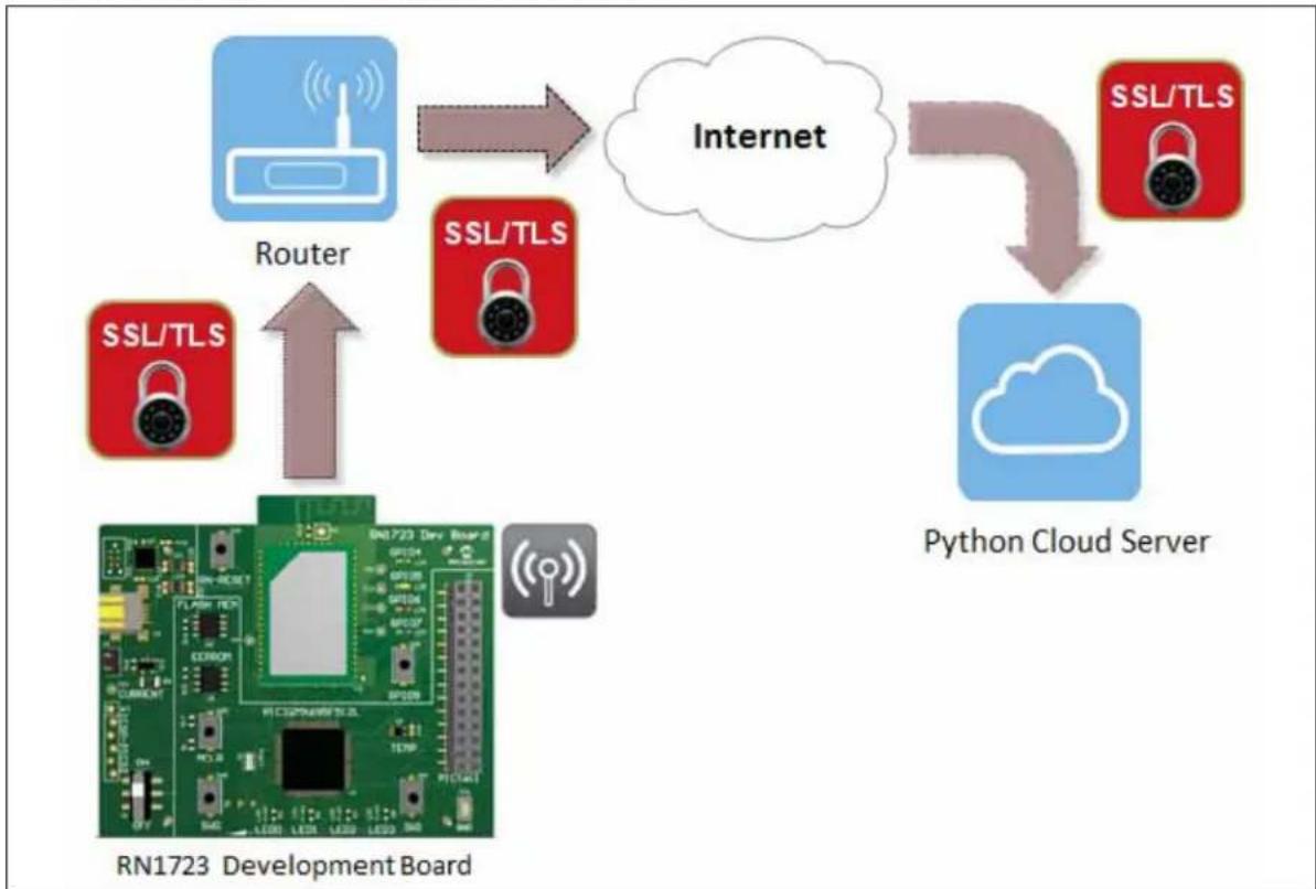
One of the purposes of the RN1723 Development Board is to demonstrate to customers how the RN1723 module may be used in IoT applications. The RN1723 Development Board incorporates the main components and features that make connecting to and transmitting data to a Web-based server a straightforward process for designers.
Figure 1-1 shows a typical system diagram of how the RN1723 Development Board may be deployed in an Internet of Things (IoT) application. Following the diagram are descriptions of the roles of each of the major system components.
FIGURE 1-1: IoT APPLICATION SYSTEM DIAGRAM
flowchart
graph TD
    A["Development Board RN1723"] -->|Router| B["Internet"]
    B --> C["Python Cloud Server"]
    C --> D["SSL/TLS"]
    D --> E["SSL/TLS"]
    E --> F["SSL/TLS"]
    F --> G["SSL/TLS"]
    G --> H["SSL/TLS"]
    H --> I["SSL/TLS"]
    I --> J["SSL/TLS"]
    J --> K["SSL/TLS"]
    K --> L["SSL/TLS"]
    L --> M["SSL/TLS"]
    M --> N["SSL/TLS"]
    N --> O["SSL/TLS"]
    O --> P["SSL/TLS"]
    P --> Q["SSL/TLS"]
    Q --> R["SSL/TLS"]
    R --> S["SSL/TLS"]
    S --> T["SSL/TLS"]
    T --> U["SSL/TLS"]
    U --> V["SSL/TLS"]
    V --> W["SSL/TLS"]
    W --> X["SSL/TLS"]
    X --> Y["SSL/TLS"]
    Y --> Z["SSL/TLS"]
    Z --> AA["SSL/TLS"]
    AA --> AB["SSL/TLS"]
    AB --> AC["SSL/TLS"]
    AC --> AD["SSL/TLS"]
    AD --> AE["SSL/TLS"]
    AE --> AF["SSL/TLS"]
    AF --> AG["SSL/TLS"]
    AG --> AH["SSL/TLS"]
    AH --> AI["SSL/TLS"]
    AI --> AJ["SSL/TLS"]
    AJ --> AK["SSL/TLS"]
    AK --> AL["SSL/TLS"]
    AL --> AM["SSL/TLS"]
    AM --> AN["SSL/TLS"]
    AN --> AO["SSL/TLS"]
    AO --> AP["SSL/TLS"]
    AP --> AQ["SSL/TLS"]
    AQ --> AR["SSL/TLS"]
    AR --> AS["SSL/TLS"]
    AS --> AT["SSL/TLS"]
    AT --> AU["SSL/TLS"]
    AU --> AV["SSL/TLS"]
    AV --> AW["SSL/TLS"]
    AW --> AX["SSL/TLS"]
    AX --> AY["SSL/TLS"]
- The on-board RN1723 module provides the Wi-Fi connectivity capabilities. When associated to a Wi-Fi Access Point, a Wi-Fi network is formed, allowing the RN1723 module to transmit information to and from the cloud-based server.
- The PIC32 device on the board provides the means for customers to create their custom IoT client application. The firmware that manages the customer's specific application, such as a thermostat, a wearable device, or a door lock, resides within the PIC32 device. Additionally, Microchip provides the wolfSSL security suite in library form, which enables customers to provide a secure link between the RN1723 module and their remote server. This security suite is resident on the PIC32 device.
The PIC32 device is also used to configure the RN1723 module, oversees its operation, captures data from external sensors, and passes that data, via the Wi-Fi module, up to the server. Similarly, the PIC32 device receives and processes data that is returned from the server via the RN1723 module.
• To assist with the development of an IoT application, a sample server written in Python is included as part of the RN1723 Development Board package. This server may be resident in the cloud or on a local computer.
• The RN1723 Development Board also contains a number of sensors:
- Potentiometer
- Temperature sensor
- Switches and LEDs
- Tilt-vibe sensor
These components are used in a number of ways, including waking up the RN1723 module, indicating the module status, and providing the source of information that is transmitted to the server.
1.2.1 Demonstration System
Now that the major system components have been identified, the following is a brief description of how the IoT client application provided with the RN1723 Development Board functions to make a complete demonstration system.
- The RN1723 module and the PIC32 device are woken from sleep on a regular schedule. Initially it occurs once every 5 seconds; however, this interval may be changed by the user.
- After waking up, the RN1723 module associates to the access point and opens a socket to the server. In parallel, the PIC32 device gathers data from the external sensors that are on the board (e.g., LEDs, switches, potentiometers, etc.). The PIC32 device packages this wake-up "status message" into JSON format and sends it the RN1723 module. The RN1723 then prepends the appropriate HTTP header information and sends it over the Internet to the server.
- The server, after receiving the "status message", has the option of asking the RN1723/PIC32 client device to perform additional tasks, or instructing the device to go back the sleep.
- Regardless of the intervening actions, the final instruction from the server to the client is always to go back to sleep. During the time that the RN1723 module and the PIC32 device are asleep, the entire development board draws only 4 A.
1.2.2 Additional Features
In addition to the hardware components, which are described in Chapter
- "Hardware", the RN1723 Development Board includes a sample IoT client firmware for the PIC32 device, a sample Python-based server, a UART device driver for the RN1723 module, as well as application code that demonstrates how to integrate the RN1723 module with the wolfSSL security suite.
In summary, the RN1723 Development Board is an excellent starting point for designers interested in developing and experimenting with the mechanics of creating an embedded IoT client device.
NOTES:
Chapter 2. Hardware
This chapter describes the hardware features of the RN1723 Development Board. The following topics are discussed:
• Development Board Layout and Components
- Hardware Features
2.1 DEVELOPMENT BOARD LAYOUT AND COMPONENTS
Representations of the layout for the RN1723 Development Board included in the kit are shown in Figure 2-1 and Figure 2-2.
The top assembly of the board includes these key features, as indicated in Figure 2-1.
-
RN1723 IEEE 802.11 b/g Wi-Fi Transceiver (U2).
-
PIC32MX695F512L 32-bit microcontroller (U1).
-
Power supply through USB/AA batteries (J3).
-
Eight LED status indicators (LED0-LED3, GPIO4-GPIO7).
-
Push buttons (MCLR, RN-RESET, GPIO9, SW0, SW1).
-
ON/OFF switch (S1).
-
6-pin programming/debug port (J1).
-
PICtail expansion port (J6).
-
256K SPI EEPROM (U5).
-
1 MB SST Flash memory (U6).
-
PIC16F1455 8-bit microcontroller; USB-UART converter (U7).
-
MCP9700A temperature sensor (U9).
-
PIC32 device power control jumper (J4).
FIGURE 2-1: RN1723 DEVELOPMENT BOARD (TOP LAYOUT)
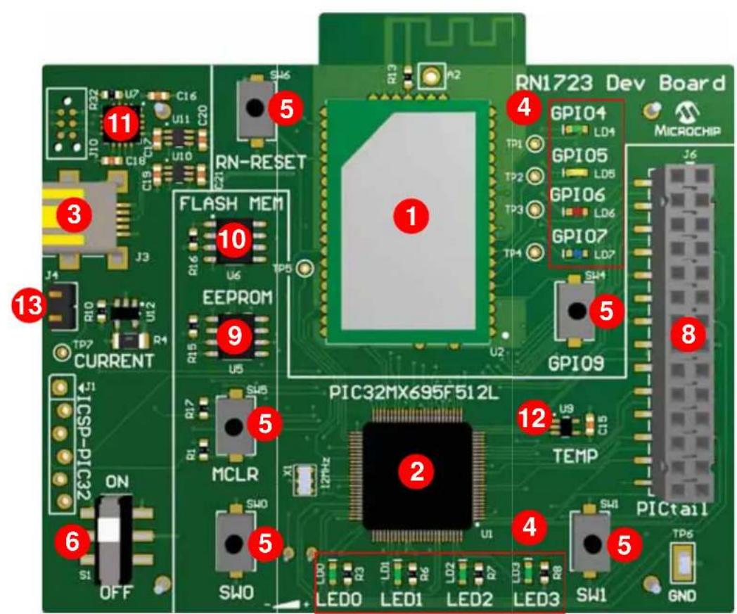
text_image
RN1723 Dev Board GPIO4 LD4 GPIO5 LD8 GPIO6 LD6 GPIO7 LD7 MICROCHIP J6 1 4 5 6 7 8 9 10 11 12 LED0 LED1 LED2 LED3 SW1 GND R2 U7 C16 U11 C20 S46 A2 RN-RESET FLASH MEM ECPROM TP7 U2 TP5 U6 U5 U2 CURRENT J1 ICSP-PIC32 ON S1 OFF MCLR SW0 ZMH21 2 PIC32MX695F512L TEMP SW1 PICTailThe bottom assembly of the board includes these key features, as indicated in Figure 2-2.
- Tilt/Vibe sensor.
- Potentiometer.
- Magnetic reed sensor (SW2).
- AA battery receptacle (BT1, BT2).
FIGURE 2-2: RN1723 DEVELOPMENT BOARD (BOTTOM LAYOUT)
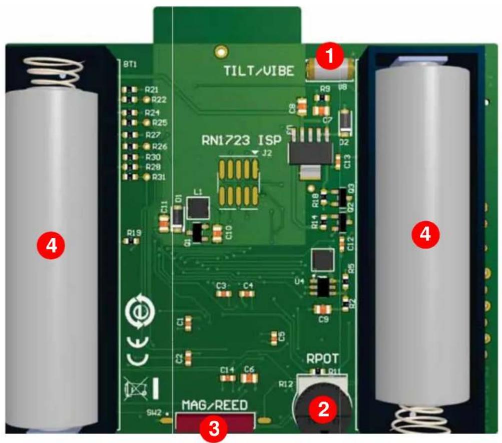
text_image
8T1 R21 R22 R24 R25 R27 R26 R30 R28 R31 C11 D1 L1 C10 RN1723 ISP J2 R9 C7 D2 C13 R14 R18 Q2 Q3 C3 C4 U4 C9 C1 S1 C14 C6 RPOT R12 SW2 MAG/REED 1 2 3 4 5 62.2 HARDWARE FEATURES
This section provides detailed descriptions of the following key features of the development board. Refer to Figure 2-1 and Figure 2-2 for their physical layout locations.
2.2.1 RN1723 IEEE 802.11 b/g Wi-Fi Transceiver Module
The RN1723 IEEE 802.11 b/g Wi-Fi Transceiver Module provides wireless connectivity to the development board. Host communication is through the UART of the PIC32MX695F512L microcontroller on the board.
2.2.2 Processor Support
The RN1723 Development Board is designed with a permanently mounted (i.e., soldered) PIC32MX695F512L microcontroller.
2.2.3 Power Supply
The development board can be powered by two AA batteries or through the USB cable. The battery voltage is monitored and boosted by the MCP1642 Synchronous Boost Regulator.
2.2.4 LEDs
There are two sets of LEDs on the board. The four green LEDs, LED0-LED3, are connected to the PORTE pins of the PIC32 microcontroller. To turn on the LEDs, the port pins need to be set High.
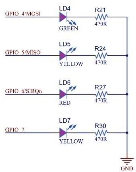
LEDs GPIO 4-GPIO7 are connected to the RN1723 module as I/Os to the module. Their individual functions are defined in Table 2-1.
TABLE 2-1: GPIO4-GPIO7 FUNCTIONS
| Pin Name | LED Color | Function |
| GPIO4 Green | Goes High | after the RN1723 module has associated/authenticated and has a valid IP address. |
| GPIO5 Yellow | Set | this pin High to trigger a TCP connection or Low to disconnect. |
| GPIO6 Red | This | pin asserts High when a socket is open, and Low when a socket is closed. |
| GPIO7 Blue | This | pin asserts High when a client connects to WEB_APP to configure the WiFi module. |
2.2.5 Switches
The RN1723 Development Board has the following switches:
- ON/OFF – This slider controls the main power to the board. To turn on power to the board, move the S1 slider to the ON position
- SW0 – This active-low push button switch is connected to RD4 of the PIC32 microcontroller
- SW1 – This active-low push button switch is connected to RD13 of the PIC32 microcontroller
- MCLR – This active-low push button switch can be used to reset the PIC32 microcontroller
- RN-RESET – This active-low push button switch is connected to the RESET pin of the RN1723 module
- GPIO9 – This active-low push button switch is connected to the GPIO9 pin of the RN1723 module
2.2.6 Programming/Debug Port
Connector J1 provides access to the PIC32 microcontroller's debug pins. It is used to program or re-flash the development board with new firmware.
2.2.7 PICtail Expansion Port
Connector J6 provides access to the PIC32 microcontroller's spare I/O pins. These pins can function as general purpose I/O ports or as an SPI, I^2C , or UART interface to an external circuit.
2.2.8 EEPROM (25LC256)
The development board has a 256K SPI Bus Serial EEPROM for storing and retrieving network or application-specific information, which is connected to SPI4 of the PIC32 microcontroller.
2.2.9 Flash Memory (SST25VF080B)
This device features an 8-Mbit SPI Serial Flash for over-the-air firmware updates of the 32-bit microcontroller, which is connected to SPI4 of the PIC32 microcontroller.
2.2.10 PIC16F1455 (USB-to-UART converter)
The PIC16F1455 8-bit microcontroller translates the USB over UART on U3 of the PIC32 microcontroller.
2.2.11 MCP9700 Temperature Sensor
The temperature sensor (MCP9700A) is a low-power linear active thermistor IC. To minimize power consumption, the sensor is powered from a port pin. On power-up, the sensor output can be measured after one minute. The internal Analog-to-Digital Converter (ADC) of the microcontroller can be used to measure the temperature value.
2.2.12 PIC32 Device Power Control Jumper (J4)
If the jumper on J4 is installed, the PIC32 microcontroller will always be powered on. If the jumper is not installed the operational state of the RN1723 module determines whether the 32-bit microcontroller is on or off. This enables a user to test the power consumption of the low-power client. To measure the power consumption, a test point, TP7, is provided.
The application can be used to construct a sleep profile for the sleep wake cycle of the RN1723 module. For more information about putting the RN1723 module to sleep, refer to the "WiFi Command Reference Manual" (DS50002230). Table 2-2 lists the RN1723 module modes and the PIC32 MCU states depending on the jumper position.
TABLE 2-2: JUMPER STATE DEFINITIONS
| Jumper Position RN1 | 723 Module Mode PIC32MZ695F512L MCU State | |
| Installed Awake P | Powered on | |
| Installed Asleep | Powered on | |
| Not installed | Awake Powered on | |
| Not installed | Asleep | Powered off |
2.2.13 Tilt/Vibe sensor
The Tilt/Vibe sensor is connected directly to the RN1723 module through the SENSOR3 pin and may be used to wake the module on motion detection.
2.2.14 Potentiometer
The potentiometer is connected to the PIC32 microcontroller on analog pin AN2/RB2 to demonstrate how to connect an analog input sensor.
2.2.15 Magnetic/Reed Sensor
The Magnetic/Reed sensor is connected directly to the RN1723 module via the SNSOR0 pin and can also be used to wake the RN1723 module. However, on the current version of the development board, this IC is not populated. If this functionality is desired, it is up to the user to add this component to the development board. Refer to the schematics and bill of materials for details.
Chapter 3. Initial Development Board Configuration
This chapter describes how the configure the development board to communicate with a server. The following topics are included:
- Setting up the Python™ Server
- Setting up The RN1723 Embedded Client
• Sample Terminal Output - Advanced Settings
Out of the box, the demonstration for the RN1723 Development Board uses a python script to set up a laptop/PC as a host. Customers can use this platform to develop and test their embedded client application prior to setting up a production cloud-based hosting service.
Figure 3-1 provides a top-level diagram detailing the objective of the system operation.
To set up the Python server, users will need to install python and the necessary packages that support SSL before launching the server script. After the server is set up and running properly, the RN1723 Development Board will be able to connect to the server as a client and post the system updates to the server.
The following sections describe the necessary steps to set up a computer as a server for Windows ^® , Mac OS ^® , and Linux.
3.1.1 Setting Up the Python Server for Windows 7
To set up the Python server for Windows 7, do the following:
- Install python, version 2.7.10 or later.
a) Download and run the installer from:
https://www.python.org/downloads/release/python-2710/
b) Add the Python directory to your system PATH.
Note: The pip package will be installed with Python 2.7 or later.
- Install pybottle by opening a command shell (click Start ( [ ] ) and enter cmd in the search box) and entering the following command:
python -m pip install bottle
- Install CherryPy, version 3.2.3 by entering the following command:
python -m pip install cherrypy==3.2.3
- Launch the server script from the installed directory by entering the following command:
python ServerMainSSL.py
3.1.2 Setting Up a Python Server for Mac OS
The instructions provided in this section assume that a previous version of openssl has not been installed. If that is not the case, all previous versions must first be uninstalled before proceeding.
Only openssl version 1.0.0 or later supports the RN1723 Secure Server Script using TLS1.2. To install openssl, do the following:
- Use Homebrew (http://brew.sh) to install the latest version of openssl using the following commands in a terminal window, while forcing the links so that Python will use the right version of openssl.
brew update
brew install openssl
brew link --force openssl
- Reinstall Python to use the latest openssl.
brew install python --with-brewed-openssl
- To verify that python was updated, run the following command and verify that the version number of the operating system is greater than 1.0.2d.
python -c 'import ssl; print ssl.OPENSSL_VERSION'
- Install pip by opening a terminal application (Applications > Utilities > Terminal) and entering the following command:.
\$ sudo easy_install pip
- Install pybottle by entering the following command:
\$ sudo pip install bottle
- Install Cherrypy version 3.2.3 by entering the following command:
\$ sudo pip install cherrypy==3.2.3
- Launch the server script by entering the following command:
\$ sudo python ServerMain.py
3.1.3 Setting Up a Python Server for Linux
- Install Python 2.7.x by opening a terminal application and entering the following command:
\$ sudo apt-get install python
- Install pip by entering the following command:
\$ sudo apt-get install python-pip
- Install pybottle by entering the following command:
\$ sudo pip install bottle
- Install cherrypy version 3.2.3 by entering the following command:
\$ sudo pip install cherrypy==3.2.3
- Launch the server script by entering the following command:
\$ sudo python ServerMain.py
3.1.4 Reading the Server IP Address
After the server is set up on a host PC/laptop, please read the IP address of the laptop/PC using the command ipconfig (Windows) or ifconfig (Mac/Linux). Figure 3-2 shows a sample screen.
While setting up the RN1723 Client, the host address is required to be set according to the output of ifconfig/ipconfig (e.g., 192.168.1.111). It is important to ensure that both the client and server are on the same subnet.
FIGURE 3-2: ifconfig EXAMPLE
Last login: Fri Dec 11 13:58:49 on ttys000
CHN-MLT-C13839:~ c13839$ ifconfig
lo0: flags=8049<UP,LOOPBACK,RUNNING,MULTICAST> mtu 16384
options=3<RXCSUM,TXCSUM>
inet6 ::1 prefixlen 128
inet 127.0.0.1 netmask 0xff000000
inet6 fe80::1%lo0 prefixlen 64 scopeid 0x1
nd6 options=1<PERFORMNUD>
gif0: flags=8010<POINTPOINT,MULTICAST> mtu 1280
stf0: flags=0<> mtu 1280
en0: flags=8863<UP,BROADCAST,SMART,RUNNING,SIMPLEX,MULTICAST> mtu 1500
options=10b<RXCSUM,TXCSUM,VLAN_HWTAGGING,AV>
ether 10:dd:b1:e3:17:38
inet6 fe80::12dd:b1ff:fee3:1738%en0 prefixlen 64 scopeid 0x4
inet 192.168.1.111 netmask 0xfffff00 broadcast 192.168.1.255
nd6 options=1<PERFORMNUD>
media: autoselect (100baseTX <full-duplex,flow-control>)
status: active
en1: flags=8823<UP,BROADCAST,SMART,SIMPLEX,MULTICAST> mtu 1500
ether a8:bb:cf:01:26:7e
nd6 options=1<PERFORMNUD>
media: autoselect (<unknown type>)
status: inactive
fw0: flags=8863<UP,BROADCAST,SMART,RUNNING,SIMPLEX,MULTICAST> mtu 4878
lladdr 44:fb:42:ff:fe:76:e5:3a
nd6 options=1<PERFORMNUD>
media: autoselect <full-duplex>
status: inactive
en3: flags=8963<UP,BROADCAST,SMART,RUNNING,PROMISC,SIMPLEX,MULTICAST> mtu 1500
options=60<TS04,TS06>
ether d2:00:17:6e:53:a0
media: autoselect <full-duplex>
status: inactive
p2p0: flags=8802<BROADCAST,SIMPLEX,MULTICAST> mtu 2304
ether 0a:bb:cf:01:26:7e
media: autoselect
status: inactive
bridge0: flags=8863<UP,BROADCAST,SMART,RUNNING,SIMPLEX,MULTICAST> mtu 1500
options=63<RXCSUM,TXCSUM,TS04,TS06>
ether 12:dd:b1:3e:49:00
Configuration:
    id 0:0:0:0:0:0 priority 0 hellotime 0 fwddelay 0
    maxage 0 holdcnt 0 proto stp maxaddr 100 timeout 1200
    root id 0:0:0:0:0 priority 0 ifcost 0 port 0
    ipfilter disabled flags 0x2
member: en3 flags=3<LEARNING,DISCOVER>
    ifmaxaddr 0 port 7 priority 0 path cost 0
nd6 options=1<PERFORMNUD>
media: <unknown type>
status: inactive
CHN-MLT-C13839:~ c13839$
3.1.5 Opening the Server Web Page
Open a Web browser and enter the following URL: https://localhost.
FIGURE 3-3: SERVER WEB PAGE EXAMPLE
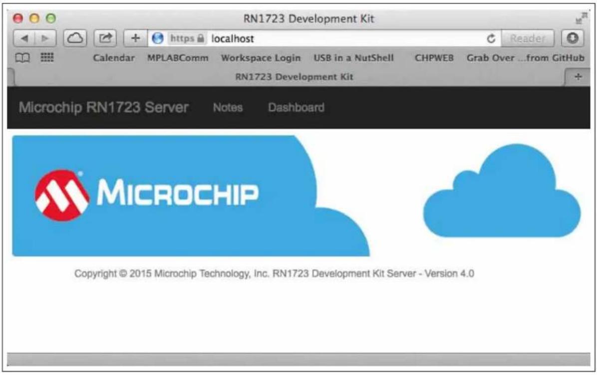
text_image
RN1723 Development Kit Calendar MPLABComm Workspace Login USB in a NutShell CHPWEB Grab Over ...from GitHub RN1723 Development Kit Microchip RN1723 Server Notes Dashboard MICROCHIP Copyright © 2015 Microchip Technology, Inc. RN1723 Development Kit Server - Version 4.03.2 SETTING UP THE RN1723 EMBEDDED CLIENT
3.2.1 Provisioning the RN1723 Development Board Using a Serial Port Terminal Application
- Connect a mini-USB to Type A USB cable between the RN1723 Development Board and the laptop/PC.
-
Use a serial port terminal emulator and configure it to the following settings:
-
Baud Rate: 115200
- Data bits: 8
- Parity: None
- Stop bits: 1
-
Flow Control: None
-
Ensure that the jumper is installed on J4.
-
Press any key to display the main menu in the terminal application, as shown in Figure 3-4.
FIGURE 3-4: TERMINAL APPLICATION MENU
Choose from the below options:
a. Configure PIC32 to RN-UART BAUDRATE
b. Pass Terminal to RN-UART
c. Factory Reset System

1. Restore RN1723 Dev Board Default Settings
2. Scan for networks to join
3. Configure SSID, Passphrase
4. Change DNS Name
5. Change Host IP Address
6. Change Destination port
7. Change RN SYS Wake time
8. Change RN1723 Dev Board Base-URI
9. Enter Date and Time (Used for SSL Peer Validation)

Press 'ESC' to exit PIC32 Console Mode
>>
- Select option 5 and configure the host server address. When prompted "Enter Host IP Address", enter the IP address of the host. For example, 192.168.1.27. The message "Programming host IP..." followed by "CMD" will appear indicating the IP address has been programmed. As shown in Figure 3-5, all commands entered by the user are shown in bold type. If a user command is successfully executed, the "OK" response is returned from the RN1723 module.
FIGURE 3-5: SETTING THE HOST SERVER ADDRESS
Press 'ESC' to exit PIC32 Console Mode
>>
5
Enter Host IP Address
192.168.1.27
Programming host IP...
CMD
<1.00>
set ip host 192.168.1.127
OK
<1.00>
set dns name 0
OK
<1.00>
save
Storing in config
<1.00>
exit
>>
- Select option 3, enter the SSID, and then the Passphrase of the AP to which the RN1723 Development Board is to be connected. As shown in Figure 3-6, all commands entered by the user are shown in bold type. If a user command is successfully executed, the "OK" response is returned from the RN1723 module.
FIGURE 3-6: SETTING THE SSID AND PASSPHRASE
>>
3
Enter SSID
roving1
Programming SSID...
CMD
<1.00>
set wlan ssid roving1
OK
<1.00>
save
Storing in config
<1.00>
exit
Enter Passphrase
>>
rubygirl
Programming Passphrase...
CMD
<1.00>
set wlan pass rubygirl
OK
<1.00>
Note: The 32-bit microcontroller will not be powered off during the RN1723 sleep cycle if the jumper is installed at position J4. Remove the jumper if you want to evaluate low power operation.
After provisioning the RN1723 Development Board onto a network, the device will communicate periodically to the host server (Cloud) with status information. Once the data exchange is completed, the RN module will return to Sleep mode.
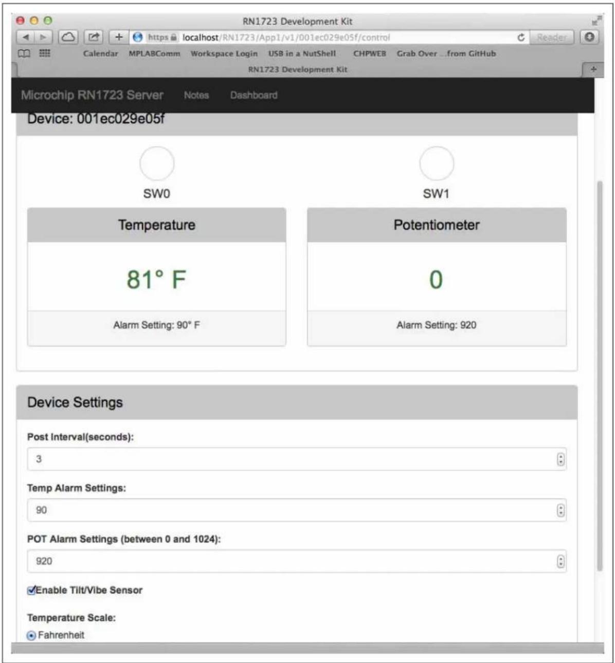
For configuring the application system settings (wake-up interval, alarm thresholds), the user can modify the settings on the server web page.
3.2.1.1 SERVER WEB PAGE
The URL to the server web page is:
https://
where,
Figure 3-7 show the device status information available on the web page once the device starts communicating with the host server.
FIGURE 3-7: DEVICE STATUS INFORMATION
text_image
RN1723 Development Kit Calendar MPLABComm Workspace Login USB in a NutShell CHPWEB Grab Over ...from GitHub RN1723 Development Kit Microchip RN1723 Server Notes Dashboard Device: 001ec029e05f SW0 SW1 Temperature Potentiometer 81° F 0 Alarm Setting: 90° F Alarm Setting: 920 Device Settings Post Interval(seconds): 3 Temp Alarm Settings: 90 POT Alarm Settings (between 0 and 1024): 920 Enable Tilt/Vibe Sensor Temperature Scale: Fahrenheit3.3 SAMPLE TERMINAL OUTPUT
Case 1: Wakeup > Put/Post STATUS > Server 303 See Other > Get SYSTEM > Server 200 OK > Sleep
Post to server-
PUT /RN1723/App1/v1/0006666dea2d/status HTTP/1.1
Host: lpcl.cloud.microchip.com
Accept: application/json
Connection: keep-alive
Content-Type: application/json
Content-Length: 111
{"msgHeader": {"uuid": "0006666dea2d"}, "status": {"potvalue": 500, "temperature": 75, "switches": 3, "alarms": 3})

Response from server-
HTTP/1.1 303 See Other
Content-Length: 128
Content-Type: application/json
Date: Thu, 02 Jul 2015 16:52:47 GMT
Server: ip-10-0-0-71
{"_links": {"self": {"href": "/0006666dea2d"}, "next": {"href": "/0006666dea2d/system"}}, "msgHeader": {"uuid": "0006666dea2d"}})

Post to server-
GET /RN1723/App1/v1/0006666dea2d/system HTTP/1.1
Host: lpcl.cloud.microchip.com
Accept: application/json
Connection: keep-alive
Content-Type: application/json
Content-Length: 0

Response from server-
HTTP/1.1 200 OK
Content-Length: 188
Content-Type: application/json
Date: Thu, 02 Jul 2015 16:52:48 GMT
Server: ip-10-0-0-71
{"_links": {"self": {"href": "/0006666dea2d"},{"msgHeader": {"uuid": "0006666dea2d"},{"system": {"tiltVibe": true, "temperatureThreshold": 72, "publishPeriod": 4, "potMaxThreshold": 400}}}

Successfully communicated to host.
RN going to sleep
Case 2: Wakeup > Put/Post STATUS > Server 200 OK > Sleep
RN with CyaSSL Demo Version: 1.00
Build Date: Jul 1 2015 15:07:18
Post to server-
PUT /RN1723/App1/v1/0006666dea2d/status HTTP/1.1
Host: lpcl.cloud.microchip.com
Accept: application/json
Connection: keep-alive
Content-Type: application/json
Content-Length: 111
{"msgHeader": {"uuid": "0006666dea2d"}, "status": {"potvalue": 500, "temperature": 76, "switches": 3, "alarms": 3}}
Response from server-
HTTP/1.1 200 OK
Content-Length: 86
Content-Type: application/json
Date: Thu, 02 Jul 2015 16:52:54 GMT
Server: ip-10-0-0-71
{"_links": {"self": {"href": "/0006666dea2d"}}, "msgHeader": {"uuid": "0006666dea2d"}}}
Successfully communicated to host.
RN going to sleep
3.4 ADVANCED SETTINGS
The following are the default settings used by the demonstration application:
- Wake-up Interval: 15 seconds
- Remote port: 443
• Baud rate (RN Module): 115200 - Module Base URI: /RN1723/App1/v1
To modify any of the default settings, the user may use the available menu options listed in Table 3-1.
3.4.1 Terminal (Console) Application Menu Options
The available console application menu options are listed in Table 3-1.
TABLE 3-1: TERMINAL (CONSOLE) APPLICATION MENU OPTIONS
| Option Feature Description | ||
| a Configure PIC32 to the RN-UART's BAUDRATE | Enables the user the configure the baud rate for the RN1723 module. | |
| b Pass terminal to RN-UART In this mode, the user can configure the RN1723 module using the WiFi commands. | ||
| c | Factory Reset System | Resets the RN1723 to its factory defaults. Refer to the “WiFi Command Reference Manual” (DS500002230) for the factory default settings of the RN1723 module. |
| 1 Restore RN1723 Demo Default Settings | Programs the RN1723 module with the default settings for the application demonstration. | |
| 2 Scan for Networks to Join Perform a scan operation and outputs the results on the terminal. | ||
| 3 | Configure SSID and Passphrase | Allows the user to provision the RN1723 module onto a network. |
| 4 Change DNS Name | Allows the user to configure the host using DNS or an IP address. If using DNS, the host IP address will be set to 0. | |
| 5 | Change Host IP Address | Allows the user to configure the host IP address when the DNS name is not available. |
| 6 Change Destination Port | The default destination port is 443 (SSL); however, the user can modify the default port using this option. | |
| 7 Change RN SYS Wake Time | The default wake time is set to 15 seconds. Users can modify the value using this option and the RN1723 Development Board will use the new value to sleep and wake-up. | |
| 8 Change LCPM Base-URI | The Base-URI is the URL for the server. Based on the requirement or changes in the server, this URL can be modified in the application. | |
| 9 Enter Date and Time | The date and time are used for the SSL Peer Validation (certificate). This option enables the user to manually enter the date and time that is used in the SSL certificate validation. RN1723 supports NTP (Network Time Protocol) and customers can also use this feature. Using the NTP for network time and date is not available in the application; in order to do this, users need to customize their client application | |
NOTES:
Appendix A. RN1723 Development Board Schematics
This appendix provides the schematic diagrams for the RN1723 Development Board and includes the following figures:
• Figure A-1: "RN1723 Module"
• Figure A-2: "Device"
• Figure A-3: “UART Level Translator/Isolation”
• Figure A-4: "USB to PIC32 Serial"
• Figure A-5: "Flash Device"
• Figure A-6: "Power Supply"
• Figure A-7: "EEPROM"
- Figure A-8: "PICtail™ connector and debug port connector"
• Figure A-9: “LEDs and Switches”
• Figure A-10: "GPIO"
• Figure A-11: "Potentiometer"
• Figure A-12: "ISP Header"
• Figure A-13: "Boost Regulator"
• Figure A-14: "Test Points"
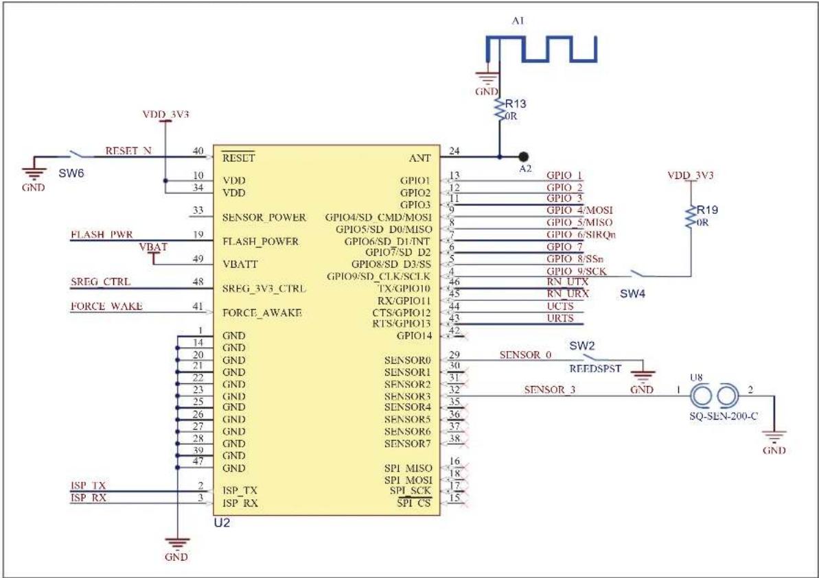
FIGURE A-1: RN1723 MODULE
text_image
VDD_3V3 RESET N SW6 GND 10 34 33 FLASH PWR VBAT 19 SREG CTRL FORCE WAKE 48 41 1 14 20 21 22 23 25 26 27 28 39 47 ISP TX ISP RX 2 3 U2 RESET ANT VDD GPIO1 GPIO2 GPIO3 SENSOR_POWER GPIO4/SD_CMD/MOSI GPIO5/SD_D0/MISO GPIO6/SD_D1/TNT GPIO7/SD_D2 VBATT GPIO8/SD_D3/SS GPIO9/SD_CLK/SCLK TX/GPIO10 RX/GPIO11 CTS/GPIO12 RTS/GPIO13 GPIO14 GND GND GND GND GND GND GND GND GND GND GND GND GND GND GND GND GND GND GND GND GND GND GND GND GND GND GND GND GND GND GND GND GND GNDFIGURE A-2: DEVICE
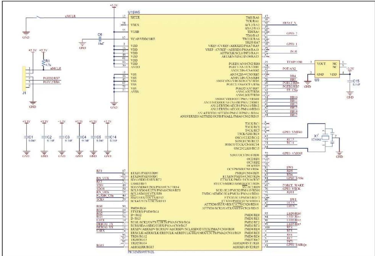
text_image
U1SW5 MCLR TMS/RA0 TCK/RA1 SCL/RA2 SDA/RA3 TDRA4 TDOR/A5 TRCLK/RA6 TRD/RA7 VDD VREF-/CV/REF-/AERXD2/PMA7/RA9 VREF-/CVREF-/AERXD3/PMA6/RA10 AETXCLK/SCL1/TNT3/RA11 AETXEN/SDAUN/T4KA15 PGED1/AN0/CN2/RB0 PGEC1/AN1/CNVRB1 AN2/CZN-CN4/RB2 AN3/CZN+/CN5/RB3 AN4/CIN-/CN6/RB4 ANS/CIN1/VRUSON/CVRB5 PGEC2/AN6/OCP/AIRB6 PGED2/AN7/RB7 AN8/C1OUT/RB8 AN9/C2OUT/RB9 AN10/CYREF/OU1/PMA15/RB10 AN11/RX/RK/AE/TX/RK/PMA12/RB11 AN12/TXD/DATCR5/PMA11/RB12 AN13/TXD/DATCO/PMA10/RB13 AN14/FXD/DAT/TXD/PMA11/PMA1/RB14 AN15/ERXD3/AETXD2/OCT/BPMALL/PMA0/CN12/RB15 TCK/RCI TCK/RC2 TCK/RC3 TSCK/SDI/RC4 OSC1/CLKR2RC12 SOSC/CN1/RC13 SOSC/CACK/RC14 OSC2/CLKR0RC15 SIDOH/XC1/NINLRID0 OC2/RD1 OC3/RD2 OC4/RD3 OC5/PWMWR/CN1/RD4 PMRD/CN1-RD5 ELXEN/PMD4/CN15/RD6 FTXCLK/PMD5/CN16/RD7 RTCC/MDRD/AEMED/DICURDS SNAC/ERID9 SCK/LC3/PACS2/PMA15/RD10 FMDC/ATMDC/IC4/PACS1/PMA14/RD11 FTND2/CSPMID2/RD12 FTND3/PMD1/CN19/RD13 ATTXD0/SSTCHRX/UCT/SCDNORD14 APTXD1/SCK3/CATX/UIRT/SN2/RD15 PMD8/RG0 PTXTR0/PMD9/RG1 D-/RG2 D-/RG3 ECON/SCK2/USTX/UJRTS/PMA5/CN8/RG6 ECR/SNDA/SDI2/UUX/PMA4/CN9/RG7 EXDV/AERDXV/ECKSDV/AECRSDV/SCL4SDO2/UJTX/PMA3/CN10/RG8 EXCLK/AERXCLK/EREFCLK/AERFCLK/SSE2/URO/T5CTS/PMA2/CN11/RG9 TRD1/RG12 TRD8/RG13 TRD2/RG14 AERXERR/RG15 AERXDE/INT2/RE9 PR32MXS93F5I2LFIGURE A-3: UART LEVEL TRANSLATOR/ISOLATION
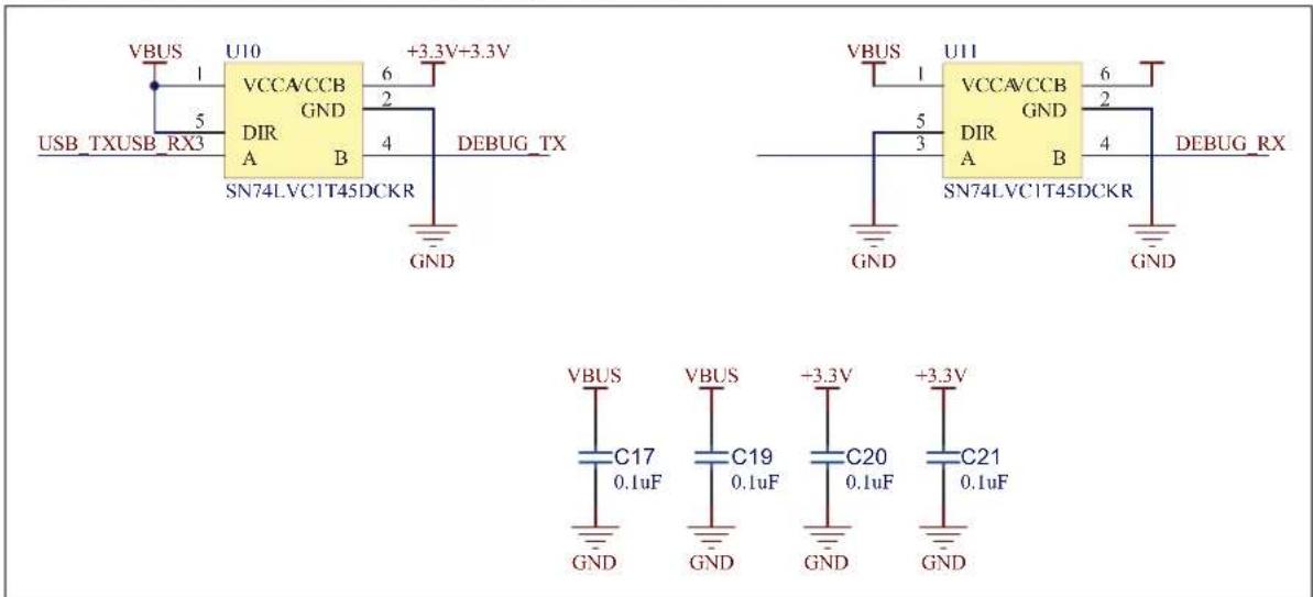
text_image
VBUS USB_TXUSB_RX3 U10 VCCA/CCB GND DIR A B SN74LVC1T45DCKR +3.3V+3.3V 6 2 4 DEBUG_TX GND VCC/A/CCB GND DIR A B SN74LVC1T45DCKR +3.3V 6 2 4 DEBUG_RX GND VBUS VCC/A/CCB GND DIR A B SN74LVC1T45DCKR +3.3V 6 2 4 DEBUG_RX GND VBUS C17 0.1uF VBUS C19 0.1uF +3.3V C20 0.1uF +3.3V C21 0.1uFFIGURE A-4: USB TO PIC32 SERIAL
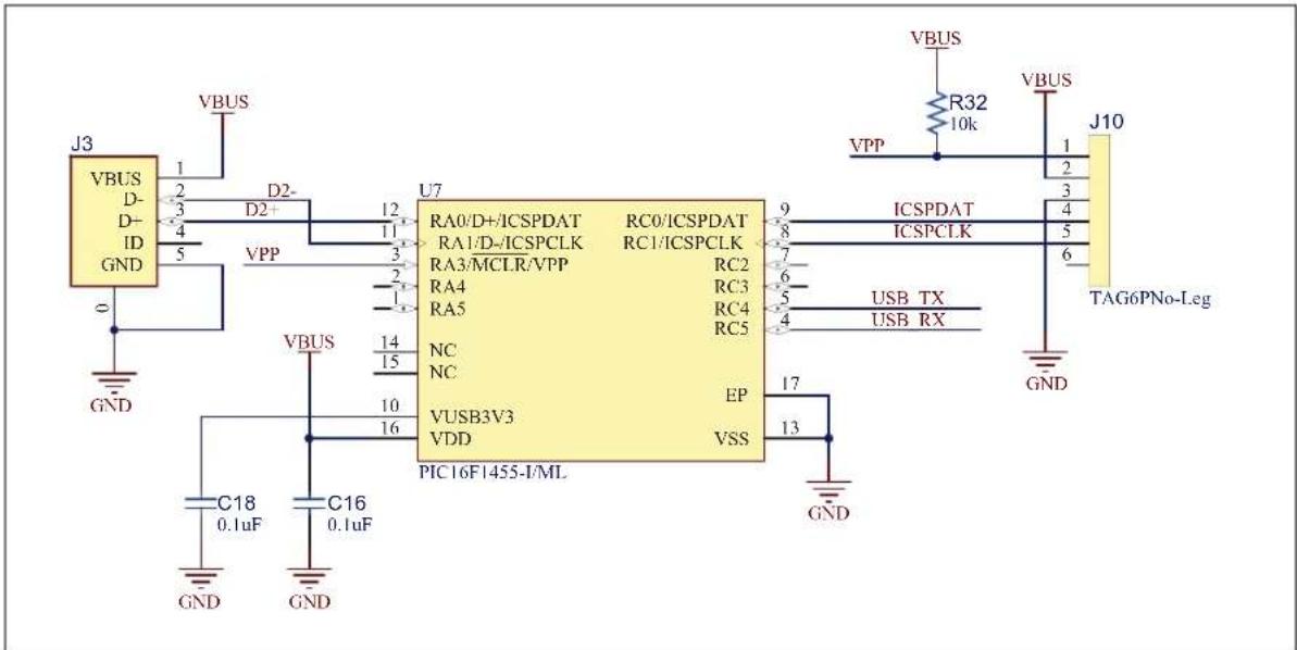
text_image
J3 VBUS D- D+ ID GND V_BUS 1 2 3 4 5 U7 RA0/D+/ICSPDAT RC0/ICSPDAT RA1/D-/ICSPCLK RC1/ICSPCLK RA3/MCLR/VPP RC2 RA4 RA5 NC VCUSB3V3 EP VDD VSS PIC16F1455-I/ML VBUS 14 15 10 16 GND C18 0.1uF C16 0.1uF GND VPP VSS 9 8 7 6 5 4 17 13 V_BUS R32 10k V_BUS J10 ICSPDAT ICSPCLK USB TX USB RX GND TAG6PNo-LegFIGURE A-5: FLASH DEVICE
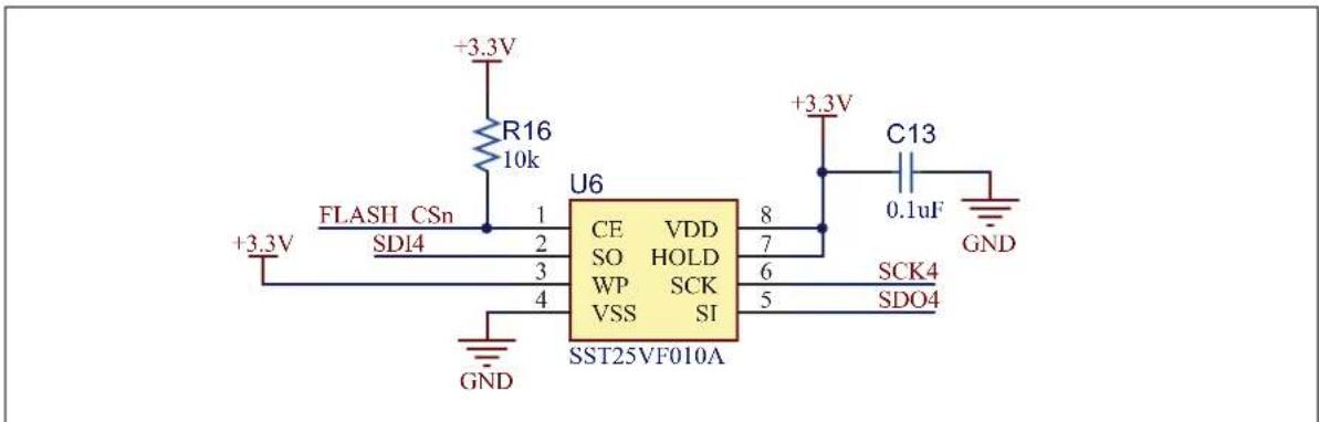
text_image
+3.3V R16 10k +3.3V FLASH CSn SD14 1 2 3 4 GND U6 CE VDD SO HOLD WP SCK VSS SI SST25VF010A 8 7 6 5 +3.3V C13 0.1uF GND SCK4 SDO4FIGURE A-6: POWER SUPPLY
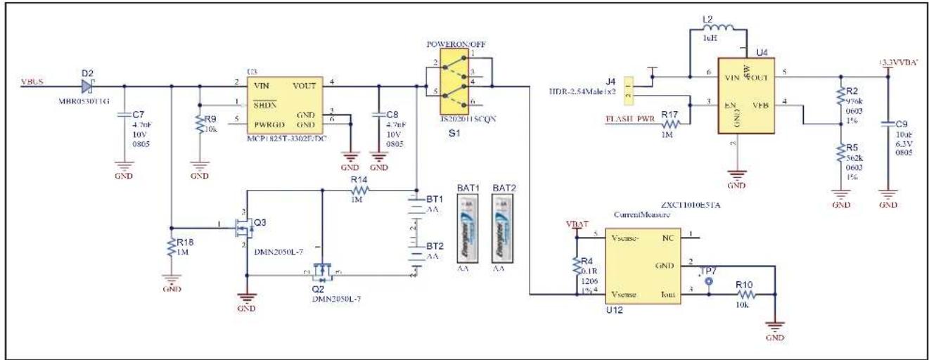
text_image
V_BUS D2 MBR05 5D11G C7 4.76F 10V 0805 GND R9 10k GND U3 VIN VOUT SHDN GND PWRGD MCP1825T-3302E/DC 1 2 3 4 5 6 7 8 9 10V 0805 C8 4.76F 10V 0805 GND GND POWERON OFF S1 IS202011SCQN J4 FLASH PWR R17 1M BT1 AA BT2 AA BAT1 BAT2 Q3 DMN2050L-7 Q2 DMN2050L-7 GND R18 1M GND ZXCT1010E51A CurrentMeasure Vscase- NC GND Vsense Iout U12 VTAT R4 0.1R 1206 1% P7 R10 10k GND I4R-2.54Male iX2 L2 1uH U4 VIN W OUT EN VHB GND R2 976k 060J 1% GND R5 562k 060J 1% GND C9 10uF 6.3V 0805FIGURE A-7: EEPROM
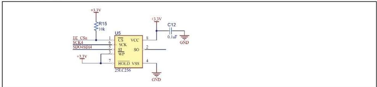
text_image
+3.3V R15 10k LE CSn 1 SCK4 6 SDO4SDI4 5 +3.3V 7 U5 CS VCC SCK SO SI 2 WP 4 HOLD VSS 25LC256 +3.3V C12 0.1uF GND GNDFIGURE A-8: PICtail™ CONNECTOR AND DEBUG PORT CONNECTOR

text_image
J6 RB13 RB12 RB15 RB14 RB11 RB10 RD11 SDO4 U6RX SDI4 U6TX SCK4 RC14 RF3RC13 RD6 RF0RB5 RB4 RG2 RG1 INT1 RG0 INT0 RG3 SSM-114-S-DV +3.3V GND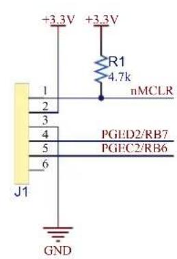
text_image
+3.3V +3.3V R1 4.7k nMCLR 1 2 3 4 5 6 J1 PGED2/RB7 PGEC2/RB6 GNDFIGURE A-9: LEDS AND SWITCHES
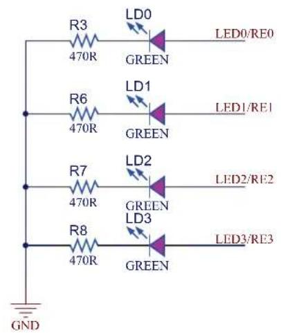
text_image
R3 470R LD0 GREEN LED0/RE0 R6 470R LD1 GREEN LED1/RE1 R7 470R LD2 GREEN LED2/RE2 R8 470R LD3 GREEN LED3/RE3 GND
text_image
SW0 GND SW1 SW1 GNDFIGURE A-10: GPIO
text_image
GPIO 4/MOSI LD4 GREEN R21 470R GPIO 5/MISO LD5 YELLOW R24 470R GPIO 6/SIRQn LD6 RED R27 470R GPIO 7 LD7 YELLOW R30 470R GND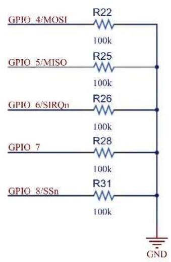
text_image
GPIO 4/MOSI R22 100k GPIO 5/MISO R25 100k GPIO 6/SIRQn R26 100k GPIO 7 R28 100k GPIO 8/SSn R31 100k GNDFIGURE A-11: POTENTIOMETER

text_image
+3.3V R12 10k R11 470R POT/AN2 GNDFIGURE A-12: ISP HEADER
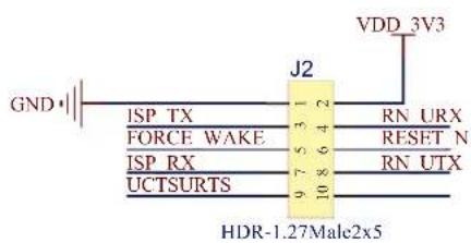
text_image
GND J2 VDD 3V3 ISP TX FORCE WAKE ISP RX UCTSURTS 9 7 5 4 3 2 10 8 6 RN URX RESET N RN UTX HDR-1.27Male2x5FIGURE A-13: BOOST REGULATOR

text_image
VBAT L1 1uH D1 MBR0530T1G VDD_3V3 C10 10uF 6.3V 0805 SREG CTRL 1 Q1 DMN2050L-7 3 2 GND GND C11 10uF 6.3V 0805 GNDFIGURE A-14: TEST POINTS

text_image
TP1 TP2 TP3 TP4 TP5 GPIO_4/MOSI GPIO_5/MISO GPIO_6/SIRQn GPIO_8/SSn FORCE_WAKE TP6 5019 GNDWorldwide Sales and Service
AMERICAS
Corporate Office
2355 West Chandler Blvd.
Chandler, AZ 85224-6199
Tel: 480-792-7200
Fax: 480-792-7277
Technical Support:
http://www.microchip.com/
support
Web Address:
www.microchip.com
Atlanta
Duluth, GA
Tel: 678-957-9614
Fax: 678-957-1455
Austin, TX
Tel: 512-257-3370
Boston
Westborough, MA
Tel: 774-760-0087
Fax: 774-760-0088
Chicago
Itasca, IL
Tel: 630-285-0071
Fax: 630-285-0075
Cleveland
Independence, OH
Tel: 216-447-0464
Fax: 216-447-0643
Dallas
Addison, TX
Tel: 972-818-7423
Fax: 972-818-2924
Detroit
Novi, M
Tel: 248-848-4000
Houston, TX
Tel: 281-894-5983
Indianapolis
Noblesville, IN
Tel: 317-773-8323
Fax: 317-773-5453
Los Angeles
Mission Viejo, CA
Tel: 949-462-9523
Fax: 949-462-9608
New York, NY
Tel: 631-435-6000
San Jose, CA
Tel: 408-735-9110
Canada - Toronto
Tel: 905-673-0699
Fax: 905-673-6509
ASIA/PACIFIC
Asia Pacific Office
Suites 3707-14, 37th Floor
Tower 6, The Gateway
Harbour City, Kowloon
Hong Kong
Tel: 852-2943-5100
Fax: 852-2401-3431
Australia - Sydney
Tel: 61-2-9868-6733
Fax: 61-2-9868-6755
China - Beijing
Tel: 86-10-8569-7000
Fax: 86-10-8528-2104
China - Chengdu
Tel: 86-28-8665-5511
Fax: 86-28-8665-7889
China - Chongqing
Tel: 86-23-8980-9588
Fax: 86-23-8980-9500
China - Dongguan
Tel: 86-769-8702-9880
China - Hangzhou
Tel: 86-571-8792-8115
Fax: 86-571-8792-8116
China - Hong Kong SAR
Tel: 852-2943-5100
Fax: 852-2401-3431
China - Nanjing
Tel: 86-25-8473-2460
Fax: 86-25-8473-2470
China - Qingdao
Tel: 86-532-8502-7355
Fax: 86-532-8502-7205
China - Shanghai
Tel: 86-21-5407-5533
Fax: 86-21-5407-5066
China - Shenyang
Tel: 86-24-2334-2829
Fax: 86-24-2334-2393
China - Shenzhen
Tel: 86-755-8864-2200
Fax: 86-755-8203-1760
China - Wuhan
Tel: 86-27-5980-5300
Fax: 86-27-5980-5118
China - Xian
Tel: 86-29-8833-7252
Fax: 86-29-8833-7256
ASIA/PACIFIC
China - Xiamen
Tel: 86-592-2388138
Fax: 86-592-2388130
China - Zhuhai
Tel: 86-756-3210040
Fax: 86-756-3210049
India - Bangalore
Tel: 91-80-3090-4444
Fax: 91-80-3090-4123
India - New Delhi
Tel: 91-11-4160-8631
Fax: 91-11-4160-8632
India - Pune
Tel: 91-20-3019-1500
Japan - Osaka
Tel: 81-6-6152-7160
Fax: 81-6-6152-9310
Japan - Tokyo
Tel: 81-3-6880-3770
Fax: 81-3-6880-3771
Korea - Daegu
Tel: 82-53-744-4301
Fax: 82-53-744-4302
Korea - Seoul
Tel: 82-2-554-7200
Fax: 82-2-558-5932 or
82-2-558-5934
Malaysia - Kuala Lumpur
Tel: 60-3-6201-9857
Fax: 60-3-6201-9859
Malaysia - Penang
Tel: 60-4-227-8870
Fax: 60-4-227-4068
Philippines - Manila
Tel: 63-2-634-9065
Fax: 63-2-634-9069
Singapore
Tel: 65-6334-8870
Fax: 65-6334-8850
Taiwan - Hsin Chu
Tel: 886-3-5778-366
Fax: 886-3-5770-955
Taiwan - Kaohsiung
Tel: 886-7-213-7828
Taiwan - Taipei
Tel: 886-2-2508-8600
Fax: 886-2-2508-0102
Thailand - Bangkok
Tel: 66-2-694-1351
Fax: 66-2-694-1350
EUROPE
Austria - Wels
Tel: 43-7242-2244-39
Fax: 43-7242-2244-393
Denmark - Copenhagen
Tel: 45-4450-2828
Fax: 45-4485-2829
France - Paris
Tel: 33-1-69-53-63-20
Fax: 33-1-69-30-90-79
Germany - Dusseldorf
Tel: 49-2129-3766400
Germany - Karlsruhe
Tel: 49-721-625370
Germany - Munich
Tel: 49-89-627-144-0
Fax: 49-89-627-144-44
Italy - Milan
Tel: 39-0331-742611
Fax: 39-0331-466781
Italy - Venice
Tel: 39-049-7625286
Netherlands - Drunen
Tel: 31-416-690399
Fax: 31-416-690340
Poland - Warsaw
Tel: 48-22-3325737
Spain - Madrid
Tel: 34-91-708-08-90
Fax: 34-91-708-08-91
Sweden - Stockholm
Tel: 46-8-5090-4654
UK - Wokingham
Tel: 44-118-921-5800
Fax: 44-118-921-5820