VSC8634/VSC8664 - Electronic component Microchip - Free user manual and instructions
Find the device manual for free VSC8634/VSC8664 Microchip in PDF.

User questions about VSC8634/VSC8664 Microchip
0 question about this device. Answer the ones you know or ask your own.
Ask a new question about this device
Download the instructions for your Electronic component in PDF format for free! Find your manual VSC8634/VSC8664 - Microchip and take your electronic device back in hand. On this page are published all the documents necessary for the use of your device. VSC8634/VSC8664 by Microchip.
USER MANUAL VSC8634/VSC8664 Microchip
3 General Description 3
3.1 Key Features .... 3
3.1.1 Copper Port RJ45 Connections 3
3.1.2 SGMII/QSGMII MAC SMA 3
3.1.3 Switch Block Control 3
3.1.4 Zarlink ZL30143 SyncE G.8262/SETS 3
3.1.5 Network Interface Microcontroller Card 3
4 Quick Start 4
4.1 Connecting the Power Supply 4
4.2 PC Software Installation 4
4.3 Connecting the Board to the PC 4
4.3.1 Changing the IP Address of the Board 4
4.4 Using the Control Software 5
4.4.1 Copper Media Operation (1000BASE-T) 5
4.4.2 Fiber Media Operation (100BASE-FX) 6
4.4.3 Fiber Media Operation (1000BASE-X) 6
4.4.4 Using the GUI 6
4.4.5 Run PHY Script Example 7
4.4.6 Automatic Media Sense (AMS) Interface Mode (1000BASE-T or 1000BASE-X) 9
4.5 Useful Registers 9
4.5.1 Ethernet Packet Generator 9
4.5.2 Copper PHY Error Counters 9
4.5.3 Fiber PHY Error Counters 9
5 Additional Information 10
1 Revision History
The revision history describes the changes that were implemented in the document. The changes are listed by revision, starting with the most current publication.
1.1 Revision 2.0
Revision 1.1 was published in April 2014. In this revision, the VSC8664 content and document format were modified.
1.2 Revision 1.0
Revision 1.0 was the first release of this document. It was published in July 2012.
2 Introduction
The VSC8664 device is a low-power, quad-port Gigabit Ethernet transceiver with four SerDes interfaces for quad-port dual media capability. It includes an integrated quad port I²C multiplexer (MUX) to control SFPs or PoE modules. The VSC8664 includes two recovered clock outputs to support Synchronous Ethernet applications.
This document describes the architecture and usage of the VSC8664 Evaluation Board (VSC8634/VSC8664EV). The board may be used to evaluate a family of devices which include the VSC8634, VSC8662, and VSC8664. These devices vary with respect to the number of ports, supported interfaces, and available features. This document specifically addresses the VSC8664 device. The Quick Start section describes how to bring-up the evaluation board along with install and run the graphical user interface (GUI), used to control the evaluation board.
Figure 1 • VSC8634/VSC8664EV Evaluation Board

natural_image
Green printed circuit board with various electronic components and connectors (no readable text or symbols)2.1 References
The following reference documents provide additional information about the operation of the VSC8574 evaluation board.
• VSC8634 Datasheet
• VSC8662 Datasheet
• VSC8664 Datasheet
• VSC8664 Evaluation Board Package
VSC8664 GUI
3 General Description
The evaluation board (Figure 1) provides the user a way to evaluate the VSC8664 device in multiple configurations. Only two of the 4 PHY ports are used on this board. Two RJ-45 connectors are provided for copper media interfaces. And two SFP cages facilitate fiber media interconnects. The MAC interface is provided only via SMA connectors.
For access to all of the features of the device, an external microcontroller is used to configure the onboard clock chip via a two wire serial bus and the VSC8664 via the MDIO bus. The graphical user interface (GUI) enables the user to access the registers.
The evaluation board uses a Zarlink device to synthesize a 25 MHz reference clock signal from a 20 MHz crystal which serves as the REFCLK input.
3.1 Key Features
3.1.1 Copper Port RJ45 Connections
PHY Port 3 (J0) uses the UDE RTA 1648BAK1A with integrated transformer while PHY Port 0 (J3) uses a generic RJ45 connector with discrete transformer (Pulse H5008).
3.1.2 SGMII/QSGMII MAC SMA
SGMII SMA connections are provided for the two exposed PHYs.
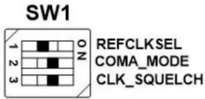
3.1.3 Switch Block Control
Confirm the SW1 switch positions as shown in the figure below, positions 1 and 2 to "OFF", positions 3 and 4 to "ON". ON = Logic 0, OFF = Logic 1.
Figure 2 • SW1 Switch Control
text_image
SW1 REFCLKSEL COMA_MODE CLK_SQUELCH3.1.4 Zarlink ZL30143 SyncE G.8262/SETS
The ZL30143 is initialized by default to provide a 25MHz LVPECL clock (pin K9) to VSC8664 REFCLK /XTAL1 input pin.
The ZL30143 can support synchronization with the VSC8664 PHY recovered clock for Sync-E operation, contact Microsemi for more information.
3.1.5 Network Interface Microcontroller Card
A "Rabbit" microcontroller card is included to facilitate a software interface to the registers on the VSC8664. The controller card has a hard coded static IP address. Refer to the label on the card for the value. This address is required by the user to initiate communications via the board and the GUI.
Note: The factory programmed Rabbit board IP address is: 10.9.70.193.
4 Quick Start
4.1 Connecting the Power Supply
The evaluation board uses +5VDC to power the on-board regulators creating the +3.3 V, +1.8 V, and +1.2 V rails which drive the devices as well as modules. The evaluation board can be powered up using the power pack which provides the +5VDC. Simply plug the AC adaptor into a wall socket and the barrel end into J18. Immediately the user should see several LEDs turn on.
The user may alternately connect the board to a bench style power supply by connecting the red banana plug to +5VDC and the black banana plug to ground. If the supply provides 3A the board should come alive as described above.
4.2 PC Software Installation
- Download the ZIP file to the PC's root directory, normally C:.
- Extract to C:\
- Double click the icon to launch the GUI (It is acceptable to drag the icon to the desktop)
4.3 Connecting the Board to the PC
The Rabbit board can interface with a PC either through a direct connection to the PC or if configured properly through a local area network. The latter option requires the user to configure the Rabbit's IP address so as to properly reside on the user's network.
The IP address of the board should be written on the Rabbit network interface daughter board card. The default value should be 10.9.70.193. You will need to use this IP address to initially access the board for operation or to change its IP address.
4.3.1 Changing the IP Address of the Board
- Determine and write down the new unique IP address you wish to change the board to.
- Directly connect an Ethernet cable from a PC to the Rabbit board.
Note: Some older PCs do not support auto-crossover on the Ethernet connection so a cross-over cable may be needed. - Launch a DOS command window by clicking on the Start->Run button and typing "cmd".
- Within the DOS command window type "Telnet"
- In Telnet, connect to the Rabbit board's address using the open command by typing "open^10.9.70.XXX".
-
10.9.70.xxx where xxx is the value on your board from the factory (typically 193).
-
You should have a prompt and be able to type help to get a list of commands available on the Rabbit.
a. If you are unable to connect, then most likely you will need to change the IP address of the connected PC to have the first 3 octets similar to the board by following the subsequent steps.
b. On the PC under Windows → Control Panel → Network Connections → Local Area Connection, right mouse click for Properties. Under the General tab highlight Internet Protocol (TCP/IP) and click on Properties. From there enter the new PC IP address such as 10.9.70.yyy where yyy is a unique value and NOT the same as the Rabbit board. Once complete, return to step 4.
-
Command the board to change its IP address to the new one by typing into Telnet now connected to the board the command: set ip
where is in the form xxx.xxx.xxx.xxx. Once you hit the IP address will be changed and the Rabbit will save the value and reboot which may take approximately 1 minute. The Telnet session will disconnect from the board. -
Change your PC IP address to the same IP network as the Rabbit board.
-
Telnet to the Rabbit board.
-
Use the following commands to complete configuration of the Rabbit board:
a. Set netmask xxx.xxx.xxx.xxx
b. Set gateway xxx.xxx.xxx.xxx
c. Save env
-
Record and inform Vitesse of the new IP address of the board when you return so that Vitesse can connect to and reconfigure the board.
-
Re-label the Rabbit board with the new IP.
4.4 Using the Control Software
Connect the VSC8634/VSC8664EV Rabbit microcontroller RJ-45 directly to the PC or through a network switch if properly configured. Apply +5VDC to the EVB.
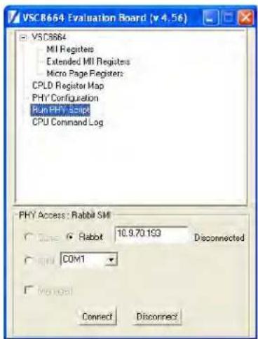
In C:\vitesse double-click the GUI shortcut to launch the GUI. The user should see the GUI connection window shown in Figure 3.
Figure 3 • GUI Connection Window
text_image
VSC8664 Evaluation Board (v 4.56) VSC8664 MI Registers Extended MI Registers Micro Page Registers: CPLD Register Map PHY Configuration Run PHY Script CPU Command Log PHY Access: Rabbit SMI ○ Close ● Rabbit 10.9.70.1G3 Disconnected ○ Open COM1 □ No need Connect DisconnectTo make a connection to the EVB, click "Rabbit" and enter the IP address of the EVB, then click on "Connect". The display next to the IP address window should change to "Connected". If it does not, check the IP address, or your network configuration until connection with the EVB can be successfully established.
4.4.1 Copper Media Operation (1000BASE-T)
To run traffic through the VSC8664's copper port, simply loopback the MAC side using coax cables, connect the media side to a traffic source, and watch traffic traverse the PHY. An internal loopback known as far end loopback can be configured instead of using coax cables.
- Set up the Copper traffic source (i.e., an IXIA or Smartbits box).
- Connect an Ethernet cable to RJ-45 Port 0.
- Connect two matched coax cables, J1 – J4 and J2 – J5. Or if no coax cables are used then enable far-end loopback mode via a register write. Write "MII Register" (PHY 0) 23'd by setting bit 3 to a "1", or load and run the "FarEndLoopback.txt" script.
- Read the link-up bit within Reg 1, bit 2 on the MII Registers window. It is recommended to read the register twice to reflect the current device status.
Traffic should be flowing.
To run traffic through the VSC8664's copper port, simply loopback the MAC side using coax cables, connect the media side to a traffic source, and watch traffic traverse the PHY. An internal loopback known as far end loopback can be configured instead of using coax cables.
4.4.2 Fiber Media Operation (100BASE-FX)
To set the device in 100BASE-FX mode perform the following:
- Set up the Copper traffic source (i.e., an IXIA or Smartbits box).
- Connect an SFP module and fiber to SFP Port 0.
- Write "MII Register" (PHY 0) 23'd 0x0304 (Sets Fiber Media to 100FX Mode).
- Write "MII Register" (PHY0) 0'd 0x9040 (Software Reset for media mode setting to have effect).
- Write "MII Register" (PHY 0) 23'd by setting bit 3 to "1" (activate Far-end loopback) if necessary.
- Write "MII Register" (PHY0) 0'd 0x0004 (Disable Auto Neg.) if necessary.
4.4.3 Fiber Media Operation (1000BASE-X)
To run traffic through the VSC8664's fiber port, simply loopback the MAC side using coax cables, connect the media side to a traffic source, configure the device registers as indicated below and watch traffic traverse the PHY. An internal loopback known as far end loopback can be configured instead of using coax cables.
- Set up the Copper traffic source (i.e., an IXIA or Smartbits box).
- Connect an SFP module and fiber to SFP Port 0.
- Write "MII Register" (PHY 0) 23'd 0x0204 (Sets Media Mode).
- Write "MII Register" (PHY0) 0'd 0x9040 (Software Reset for media mode setting to have effect).
- Write "MII Register" (PHY 0) 23'd by setting bit 3 to "1" (activate Far-end loopback) if necessary.
- Write "MII Register" (PHY0) 0'd 0x0004 (Disable Auto Neg if necessary).
Traffic should be flowing.
4.4.4 Using the GUI
Double-click on "MII Registers" on Figure 3 and the window shown in Figure 4 should appear:
Figure 4 • MII Registers GUI Window

text_image
VSC8664 - MII Registers Reg 0 - Mode Control Reg 1 - Mode Status Reg 2 - PHY Identifier Register #1 Reg 3 - PHY Identifier Register #2 Reg 4 - Auto Negotiation Advertisement Reg 5 - Auto Negotiation Link Partner Ability Reg 6 - Auto Negotiation Expansion Reg 7 - Auto Negotiation Next Page Transmit Reg 8 - Auto Negotiation Link Partner Next Page Reg 9 - 1000BASE-T Control Reg 10 - 1000BASE-T Status Reg 11 - Reserved Reg 12 - Reserved Reg 13 - Reserved Reg 14 - Reserved Reg 15 - 1000BASE-T Status Extension #1 Reg 16 - 100BASE-TX Status Extension Reg 17 - 1000BASE-T Status Extension #2 Reg 18 - Bypass Control Reg 19 - Error Counter #1 Reg 20 - Error Counter #2 Reg 21 - Error Counter #3 Reg 22 - 10BASE-T Control & Status Reg 23 - Extended PHY Control #1 Reg 24 - Extended PHY Control #2 Reg 25 - Interrupt Mask. Reg 26 - Interrupt Status Reg 27 - MAC Interface Auto-negotiation Control & Reg 28 - Auxiliary Control and Status Reg 29 - Led Mode Select Reg 30 - LED Behavior Reg 31 - Extended Page Access PHY: 0 Hex: 1040 Read Write Restore Defaults 15 Software Reset 14 Loopback 13 Forced Speed Selection Bit 0 12 Auto Negotiation Enable 11 Power Down 10 Isolate 9 Restart Auto Negotiation 8 Duplex Mode 7 Collision Test Enable 6 Forced Speed selection Bit 1 5 Reserved 4 Reserved 3 Reserved 2 Reserved 1 Reserved 0 Reserved bin None bin None bin None bin NoneVerify that the device is up and running by reading MII Register 0. It should read back 0x1040. Reading back all 0's or all 1's indicates a problem. A checked box means the bit is set to "1" if unchecked it is "0".
4.4.5 Run PHY Script Example
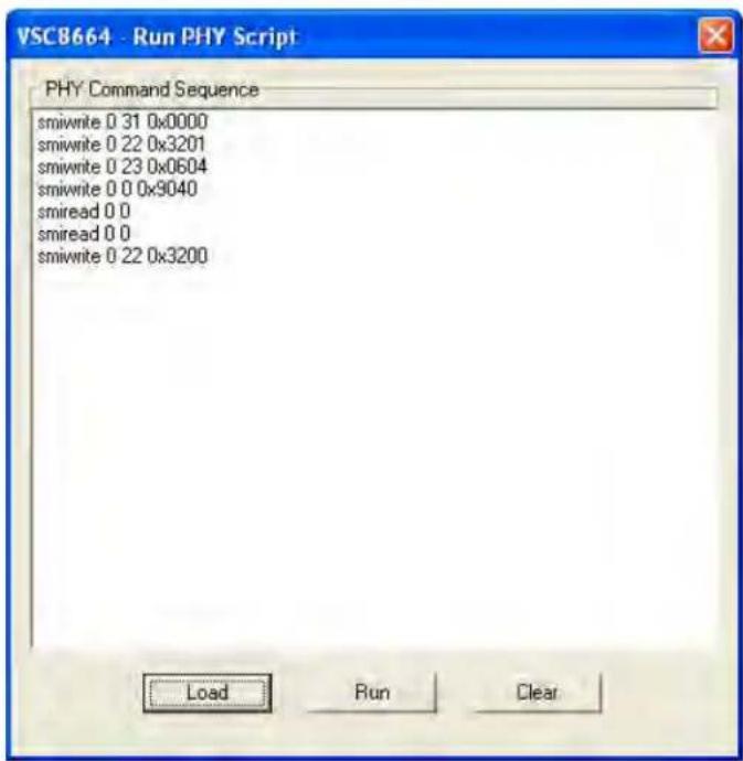
Double-clicking on "Run PHY Script" within the GUI Connection Window will launch the Run PHY Script window as shown in Figure 5. This enables a user to load a script to configure the device rather than navigating through Registers pages. A sample script showing write/read commands is shown in Figure 5. The script syntax is command, phy address (in decimal), register address (in decimal), and register content (in hexadecimal). Click on the "Load" button to browse and select the desired script file. Assuming the GUI is installed in the area listed above, navigate to C:\vitesse\VSC8664Eval\scripts and double click on the desired script filename. After opening (loading) the script, click on the "Run" button and the script will be executed. After execution is completed, you should see the read-back values in decimal as shown in Figure 6.
Figure 5 • Run PHY Script Window (After a Script is Loaded)
text_image
VSCB664 - Run PHY Script PHY Command Sequence smiwrite 0 31 0x0000 smiwrite 0 22 0x3201 smiwrite 0 23 0x0604 smiwrite 0 0 0x9040 smiread 0 0 smiread 0 0 smiwrite 0 22 0x3200 Load Run ClearFigure 6 • Run PHY Script Window (After a Script is Loaded)

text_image
VSCB664 - Run PHY Script PHY Command Sequence Command: smiwrite 0 31 0x0000 Result: 0 Command: smiwrite 0 22 0x3201 Result: 12801 Command: smiwrite 0 23 0x0604 Result: 1540 Command: smiwrite 0 0 0x9040 Result: 36928 Command: smiread 0 0 Result: 4160 Command: smiread 0 0 Result: 4160 Command: smiwrite 0 22 0x3200 Result: 12800 Command: Result: 12800 Command: Result: 12800 Load Run Clear4.4.6 Automatic Media Sense (AMS) Interface Mode (1000BASE-T or 1000BASE-X)
To set the device for AMS mode with Cat5 media or 1000Base-X fiber/SFP media with auto negotiation performed by the PHY, simply load and run the script "Fiber1000BX_AMS_SGMIIExtLoop.txt". If far-end loopback mode is desired, load and run the "FarEndLoopback.txt" script after executing the AMS script.
4.5 Useful Registers
4.5.1 Ethernet Packet Generator
ExtMII 29E is the Ethernet Packet Generator register. Refer to the datasheet for configuration options.
A Good CRC packet counter is in ExtMII 18.13:0. A read of the register reads back the good CRC packets and then clears the register so the subsequent reads will be 0 if no traffic has been received. If traffic has been received since the last read, bit 15 will be set.
4.5.2 Copper PHY Error Counters
Good RX CRC packets = ExtMII 18.13:0
Idle errors = MII 10.7:0
RX errors = MII 19.7:0
False carrier = MII 20.7:0
Disconnects = M|| 21.7:0
CRC errors = ExtMII 23.7:0
4.5.3 Fiber PHY Error Counters
Good RX CRC packets = ExtMII 18.13:0
Bad RX CRC packets = ExtMII 23.7:0
5 Additional Information
For any additional information or questions regarding the device(s) mentioned in this document, contact your local sales representative.

Microsemi.
a MICROCHIP company
Microsemi Headquarters
One Enterprise, Aliso Viejo,
CA 92656 USA
Within the USA: +1 (800) 713-4113
Outside the USA: +1 (949) 380-6100
Sales: +1 (949) 380-6136
© 2012 Microsemi. All rights reserved. Microsemi and the Microsemi logo are trademarks of Microsemi Corporation. All other trademarks and service marks are the property of their respective owners.
Microsemi makes no warranty, representation, or guarantee regarding the information contained herein or the suitability of its products and services for any particular purpose, nor does Microsemi assume any liability whatsoever arising out of the application or use of any product or circuit. The products sold hereunder and any other products sold by Microsemi have been subject to limited testing and should not be used in conjunction with mission-critical equipment or applications. Any performance specifications are believed to be reliable but are not verified, and Buyer must conduct and complete all performance and other testing of the products, alone and together with, or installed in, any end products. Buyer shall not rely on any data and performance specifications or parameters provided by Microsemi. It is the Buyer's responsibility to independently determine suitability of any products and to test and verify the same. The information provided by Microsemi hereunder is provided "as is, where is" and with all faults, and the entire risk associated with such information is entirely with the Buyer. Microsemi does not grant, explicitly or implicitly, to any party any patent rights, licenses, or any other IP rights, whether with regard to such information itself or anything described by such information. Information provided in this document is proprietary to Microsemi, and Microsemi reserves the right to make any changes to the information in this document or to any products and services at any time without notice.
Microsemi, a wholly owned subsidiary of Microchip Technology Inc. (Nasdaq: MCHP), offers a comprehensive portfolio of semiconductor and system solutions for aerospace & defense, communications, data center and industrial markets. Products include high-performance and radiation-hardened analog mixed-signal integrated circuits, FPGAs, SoCs and ASICs; power management products; timing and synchronization devices and precise time solutions, setting the world's standard for time; voice processing devices; RF solutions; discrete components; enterprise storage and communication solutions; security technologies and scalable anti-tamper products; Ethernet solutions; Power-over-Ethernet ICs and midspans; as well as custom design capabilities and services. Microsemi is headquartered in Aliso Viejo, California, and has approximately 4,800 employees globally. Learn more at www.microsemi.com.
VPPD-03084