MW100BP-OE - Speaker Atlas Sound - Free user manual and instructions
Find the device manual for free MW100BP-OE Atlas Sound in PDF.

User questions about MW100BP-OE Atlas Sound
0 question about this device. Answer the ones you know or ask your own.
Ask a new question about this device
Download the instructions for your Speaker in PDF format for free! Find your manual MW100BP-OE - Atlas Sound and take your electronic device back in hand. On this page are published all the documents necessary for the use of your device. MW100BP-OE by Atlas Sound.
USER MANUAL MW100BP-OE Atlas Sound
natural_image
Black wireless router device with two antennas and a digital display (no visible text or symbols)MWRCVR
Owner's Manual
Introduction
The AtlasLED MWRCVR wireless receiver is the ideal choice for a variety of applications ranging from classrooms and conference rooms to lecture halls and live presentations. Designed to work in conjunction with either the MWHHM wireless handheld microphone or the MWBTP wireless belt pack microphone, the MWRCVR allows for great flexibility in sound reinforcement applications. With the ability to connect to a variety of devices via the included balanced XLR or unbalanced line output, the MWRCVR can be used with a variety of amplifiers or mixers to address the needs of any installation. Multiple units can be used in a single installation since the unit receives transmission via the UHF frequency band and pairs to individual MWHHM or MWBTP on available channels. The unit can be used as a standalone piece on a shelf or desk or it can be rack mounted by itself or with a second MWRCVR using the rack mount kit, model MWRMK (sold separately).
Key Features
- Multi-function LCD display for channel / frequency, volume level, and signal strength
- Patented technology for 2-way data transfer between transmitter and receiver
• 100 frequencies available through the 25MHz signal band - Dual antennas reduce distortion
• IR sensor for connection to wireless microphone - Selectable mic or line output
Applications
- Classrooms
• Conference Rooms - Lecture Halls
• Live Presentation
MWRCVR
Owner's Manual
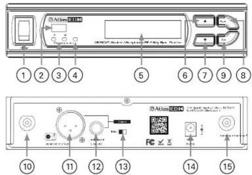
Parts and Functions
text_image
Atlas IEM 1 2 3 4 5 6 7 8 Atlas IEM 10 11 12 13 14 15- Power Switch
- IR Sensor Area
- Diversity Indicator
- Audio Signal Indicator
- LCD Display
- Up Button
- Down Button
- Synchronizing Button
- Set Button
- Antenna B Socket (BNC Type)
- Balanced Audio Output:
- Unbalanced fluid output
Atlas IED
MWRCVR
Owner's Manual
Changing Channel / Frequency
- Press and release SET button until the CHANNEL | FREQUENCY page appears | Fig 11:
- Press UP or DOWN button to select a new channel. As the channel changes, the frequency changes accordingly (Fig 2).
- After a channel is chosen, wait 5 seconds to store the setting.

Figure 1 Figure 2

Synchronizing Channels on the Receiver and Transmitter
Align infrared areas of the receiver and microphone within 12" (30cm).

Figure 3
A. Changing the receiver's channel
- Press the synchronizing button on the microphone (Fig 4).
- The microphone's LED will illuminate, indicating the frequency is being transmitted to the receiver and that the receiver is synchronizing channels with the microphone (Fig 5).
- "COPIED BY IRDA" will appear on the receiver's LCD, indicating that the receiver has been successfully synchronized (Fig 6).


Atlas IED
MWRCVR
Owner's Manual
B. Changing the microphone's channel
1. Press the synchronizing button on the receiver (Fig 7).
2. "IRDA DATA SEND" will appear on the receiver's display (Fig 8)
3. "IRDA TX FINISH" will appear to denote data transferred (Fig 9)

Figure 7

Figure 8

Figure 9
If this does not synchronize the channels, ensure the IR sensor panels are properly aligned and are located within 12" (30cm) of each other and try synchronizing again.
Channel Scanning
For an interference-free operation, a cleaner channel might be necessary if the current one receives too much interference. Before scanning, the transmitter must be switched off.
- Press and release SET button until the AUTO SCAN page appears (Fig 10).
- Press UP or DOWN button to find and locate a clear, interference-free channel (Fig 11).
- After a channel is chosen, wait 5 seconds to store the setting.

AUTO SCNN UP
AUTO SCNN DOWN

AUTO SCATHING CHANNEL: 002
Figure 10 Figure 11
MWRCVR
Owner's Manual
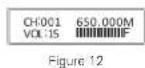
Adjusting Volume Level
- Volume adjustment can be made from the home screen (Fig 12).
- Press UP or DOWN button to choose a new level (Fig 13).
- After the level is adjusted, wait 5 seconds to store the setting.

Adjusting Squelch Level
When interference is encountered try reducing the sensitivity of the receiver, thus less susceptible to interference.
- Press and release SET button until the SQUELCH SETUP page appears (Fig 14).
- Press UP or DOWN button to choose a new level between 1 and 10 (Fig 15).
- After the level is adjusted, wait 5 seconds to store the setting.
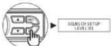
Figure 14

Figure 15
Since increasing the squelch level will also reduce the reception distance, it's recommended to choose the lowest level that can eliminate the interference. If this still does not solve the problem it means this frequency is not suitable. Adjust the squelch back to its preset level and use the scan function to locate a clear, interference-free channel.
MWRCVR
Owner's Manual
Audio Output Connection
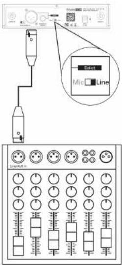
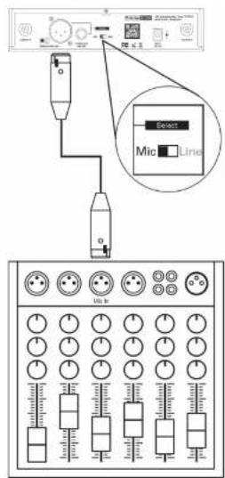
Balanced Output: XLR connector provides balanced audio output signal from this jack to the mixer / amplifier. Use an audio output cable with "XLR" or "Cannon" connector, connect one end to the balanced output jack of the receiver, and the other end to the "LINE IN" or "MIC IN" jack of the mixer / amplifier.
text_image
Select Line MicroLineFigure 16
text_image
Diagram showing connection between a device and a control panel with labeled buttons and indicatorsFigure 17
MWRCVR
Owner's Manual
Audio Output Connection
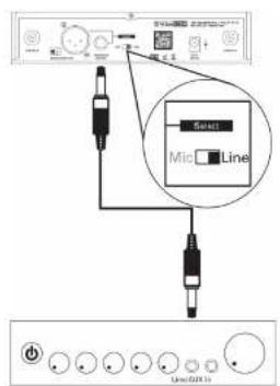
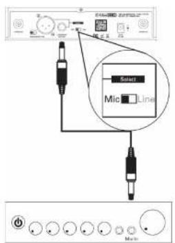
Unbalanced Output: 12 line output connector provides unbalanced audio output signal from this jack to the mixer / amplifier. Use an audio output cable with 12 PHONE PLUG connector Connect one end from the unbalanced output jack of the receiver, and the other end to the "LINE IN" or "MIC IN" jack of the mixer / amplifier.
text_image
Sweet Mic Line Line/21.1Figure 18
text_image
Select Mid LineFigure 19
Level Switch Setting: When connecting to the LINE / AUX IN of a mixer / amplifier, switch to "LINE" position (Fig 18). DO NOT use the "MIC" position as they may not deliver a sufficient output level. When connecting to the "MIC IN" jack of a mixer / amplifier, switch to "MIC" position (Fig 19). Distortion may occur at the wrong level position.
Atlas IED
MWRCVR
Owner's Manual
Receiver Installation
- For best operation, the receiver should be at least 1m above the ground and 1m away from a wall or metal surface to minimize reflections.
- The transmitter should also be at least 1m away from a wall or metal surface to minimize reflections. The microphone should also be at least 1m away from the receiver.
- Keep antennas away from noise source such as motors, automobiles, neon light as well as large metal objects.
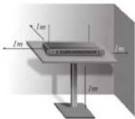
Figure 20
Rack Mounting
The receiver can be cabinet-mounted by either one or two units. If only one receiver is to be mounted, an optional kit is available (Fig 21). If two receivers are to be mounted, they can be assembled by another kit (Fig 22).
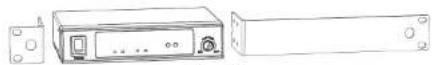
Figure 21

Figure 22
MWRCVR
Owner's Manual
System
| Frequency Range LHF | |
| UHF Operating Frequencies 470 - 60GHz | |
| Switching Bandwidth 25VHz | |
| Switchable Frequencies 100 | |
| Channels 1 | |
| Display Screen LCD | |
| Operating Range 100m Direct Sight | |
| Output Impedance Mic / Line | |
| Oscillation Type P.L. Synthesized | |
| Frequency Stability ±0.005% | |
| Receiving Method True Diversity | |
| Sensitivity-95dBm | |
| Synchronization | 2-Way |
| Image Rejection | >85dB |
| S/N Ratio | >110dB |
| Peak (Maximum) Deviation | ±40KHz |
| I.H.D. | < 0.5% |
| Antenna Socket | BNC type |
| Audio Outputs | Line (Balanced) XLR Jack: +10dBm(2.4V) / 5kΩLine (Unbalanced) 6.35mm Jack: +108m(1.2V) / 5kΩMic (Balanced) XLR Jack: -18dBm(100mV) / 600ΩMic (Unbalanced) 6.35mm Jack: -24dBm(50mV) / 600Ω |
| Squelch | RF / Noise / Picture Squech |
| Power Supply | 100 - 240vAC, 12V DC/1.6A |
| Mechanical | |
| Product Dimensions (HxWxD) | 1.73" x 7.67" x 5.91" (44mm x 200mm x 150mm) |
| Shipping Dimensions (HxWxD) | 2.90" x 16.35" x 13.50" (74mm x 415mm x 343mm) |
| Net Weight | 1.39 lbs [0.63kg] |
| Shipping Weight | 3.5 lbs (1.89kg) |
| Warranty Coverage | |
| Warranty Period | 1 Year |
Atlas IED
MWRCVR
Owner's Manual
Federal Communication Commission Interference Statement
This equipment has been tested and found to comply with the limits for a Class B digital device, pursuant to Part 15 of the FCC Rules. These limits are designed to provide reasonable protection against harmful interference in a residential installation.
This equipment generates, uses and can radiate radio frequency energy and, if not installed and used in accordance with the instructions, may cause harmful interference to radio communications. However, there is no guarantee that interference will not occur in a particular installation. If this equipment does cause harmful interference to radio or television reception, which can be determined by turning the equipment off and on, the user is encouraged to try to correct the interference by one of the following measures:
- Recorient or relocate the receiving antenna.
- Increase the separation between the equipment and receiver.
- Connect the equipment into an outlet on a circuit different from that to which the receiver is connected.
- Consult the dealer or an experienced radio/TV technician for help.
FCC Caution: To assure continued compliance, any charges or modifications not expressly approved by the party responsible for compliance could void the user's authority to operate this equipment. (Example - use only shielded interface cables when connecting to computer or peripheral devices).
This device complies with Part 15 of the FCC Rules. Operation is subject to the following two conditions: (1) This device may not cause harmful interference, and (2) This device must accept any interference received, including interference that may cause undesired operation.
Atlas IED
MWRCVR
Owner's Manual
Notes
Atlas IED
MWRCVR
Owner's Manual
Notes
Atlas IED
MWRCVR
Owner's Manual
Notes
MWRCVR
Owner's Manual
Limited Warranty
All products manufactured by AtlasIED are warranted to the original dealer / installer, industrial or commercial purchaser to be free from defects in material and workmanship and to be in compliance with our published specifications, if any. This warranty shall extend from the date of purchase for a period of three years on all AtlasIED products, including SOUNDOLIER brand, and ATLAS SOUND brand products except as follows: one year on electronics and control systems; one year on replacement parts; and one year on Musician Series stands and related accessories. Additionally, fuses and lamps carry no warranty. AtlasIED will solely at its discretion, replace at no charge or repair free of charge defective parts or products when the product has been applied and used in accordance with our published operation and installation instructions. We will not be responsible for defects caused by improper storage, misuse (including failure to provide reasonable and necessary maintenance), accident, abnormal atmospheres, water immersion, lightning discharge, or malfunctions when products have been modified or operated in excess of rated power, altered, serviced or installed in other than a workman like manner. The original sales invoice should be retained as evidence of purchase under the terms of this warranty. All warranty returns must comply with our returns policy set forth below. When products returned to AtlasIED do not qualify for repair or replacement under our warranty, repairs may be performed at prevailing costs for material and labor unless there is included with the returned product(s) a written request for an estimate of repair costs before any nonwarranty work is performed. In the event of replacement or upon completion of repairs, return shipment will be made with the transportation charges collect.
EXCEPT TO THE EXTENT THAT APPLICABLE LAW PREVENTS THE LIMITATION OF CONSEQUENTIAL DAMAGES FOR PERSONAL INJURY, ATLASIED SHALL NOT BE LIABLE IN TORT OR CONTRACT FOR ANY DIRECT, CONSEQUENTIAL OR INCIDENTAL LOSS OR DAMAGE ARISING OUT OF THE INSTALLATION, USE OR INABILITY TO USE THE PRODUCTS. THE ABOVE WARRANTY IS IN LIEU OF ALL OTHER WARRANTIES INCLUDING BUT NOT LIMITED TO WARRANTIES OF MERCHANTABILITY AND FITNESS FOR A PARTICULAR PURPOSE.
AtlasIED does not assume, or does it authorize any other person to assume or extend on its behalf, any other warranty, obligation, or liability. This warranty gives you specific legal rights and you may have other rights which vary from state to state.
MWRCVR
Owner's Manual
Service
Should your MWRCVR require service, please contact the AtlasIED warranty department through the online warranty claim process.
Online Warranty Claim Processes
- Warranty submissions are accepted at: https://www.atlasied.com/warranty_statement where the type of return Warranty or Stock return can be selected.
-
Once selected, you will be prompted to enter your login credentials. If you do not have a login, register on the site. If already logged-in, navigate to this page by selecting "Support" and then "Warranty & Returns" from the top menu.
-
In order to file a Warranty Claim, you will need:
A. A copy of the invoice / receipt of the purchased item
B. Date of Purchase
C. The product name or SKU
D. The serial number for the item (if no serial number exists, enter N/A)
E. A brief description of the fault for the claim
-
Once all required fields are completed, select the "Submit Button". You will receive 2 emails:
-
One with a confirmation of the submission
-
One with a case# for your reference should you need to contact us.
Please allow 2-3 business days for a response with a Return Authorization (RA) number and further instructions.
AtlasIED Tech Support can be reached at 1-800-876-3333 or atlasied.com/support.
Visit our website at www.Atlas|ED.com to see other Atlas|ED products