VT-TPTZ36HR-2A4 - Surveillance Camera Vitek - Free user manual and instructions
Find the device manual for free VT-TPTZ36HR-2A4 Vitek in PDF.

User questions about VT-TPTZ36HR-2A4 Vitek
0 question about this device. Answer the ones you know or ask your own.
Ask a new question about this device
Download the instructions for your Surveillance Camera in PDF format for free! Find your manual VT-TPTZ36HR-2A4 - Vitek and take your electronic device back in hand. On this page are published all the documents necessary for the use of your device. VT-TPTZ36HR-2A4 by Vitek.
USER MANUAL VT-TPTZ36HR-2A4 Vitek
text_image
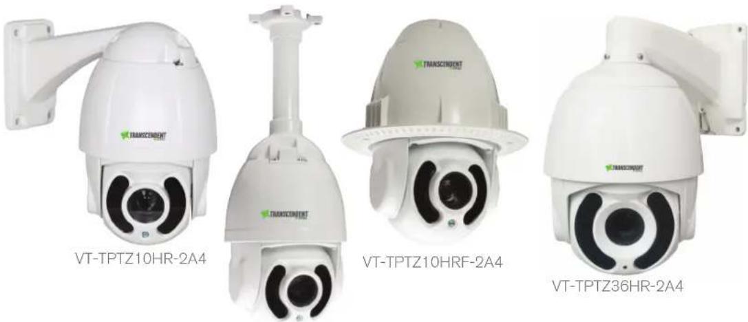
VITEK® INDUSTRIAL VIDEO PRODUCTS, INC.VT-TPTZ10HR-2A4 VT-TPTZ36HR-2A4
2.1 MegaPixel 4-IN-1 HD-TVI / AHD / CVI / CVBS PTZ Cameras with High Power IR LED Illumination
natural_image
Four white transparent surveillance cameras labeled VT-TPTZ10HR-2A4, VT-TPTZ10HRF-2A4, and VT-TPTZ36HR-2A4 (no additional text or symbols visible on the devices themselves)VT-TPTZ10HRC-2A4

TRANSCENDENT ©VITEK
FEATURES
• 1/3" 2.1 MegaPixel CMOS Sensor
• 30fps live view @ 1920 x 1080p
• HD-TVI / HD-CVI / AHD / 960H CVBS Video Output (Selectable)
• True Day/Night by IR Cut Filter
• Built-in Varifocal Lens offering 10x or 36x Optical Zoom
- Integrated High Power IR LEDs with up to 500' IR Range
• 2DNR Noise Reduction
• 220 Presets programmed with view direction, zoom, BLC, etc
• Max manual speed 480°/sec
- 360^ continuous rotation
• 16:9 Video format
• RS485 Communication / COC (Control Over Coax)
- Double layer metal body construction with IP66 Weather Resistance
• Over 1500' HD Video Transmission (Depending on cable characteristics and integrity)
• 12VDC Operation
• Power Supply Included
• 3 Year Warranty
OPTIONAL ACCESSORIES:
VT-TKB D2
Transcendent 3D Keyboard Controller for Transcendent HD-TVI PTZ Cameras
VT-TPT-C N MT
PTZ Corner Mount Adapter Bracket for Transcendent HD-TVI & IP PTZ Cameras
VT-TPT-PLMT
PTZ Pole Mount Adapter Bracket for Transcendent HD-TVI & IP PTZ Cameras

VT-T PT-P D M1
PTZ Pedestal Mount for Large 9" Transcendent PTZ Cameras

VT-T PT-J B01
J-Box for cable Management for Large 9" Transcendent PTZ Cameras
WARNINGS AND CAUTIONS
WARNING
TO REDUCE THE RISK OF FIRE OR ELECTRIC SHOCK, DO NOT EXPOSE THIS PRODUCT TO RAIN OR MOISTURE. DO NOT INSERT ANY METALLIC OBJECTS THROUGH THE VENTILATION GRILLS OF OTHER OPENINGS ON THE EQUIPMENT.
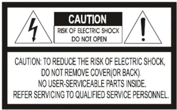
CAUTION
text_image
CAUTION RISK OF ELECTRIC SHOCK DO NOT OPEN CAUTION: TO REDUCE THE RISK OF ELECTRIC SHOCK, DO NOT REMOVE COVER(OR BACK). NO USER-SERVICEABLE PARTS INSIDE. REFER SERVICING TO QUALIFIED SERVICE PERSONNEL.EXPLANATION OF GRAPHICAL SYMBOLS

The lightning flash with arrowhead symbol, within an equilateral triangle, is intended to alert the user to the presence of uninsulated "dangerous voltage" within the product's enclosure that may be of sufficient magnitude to constitute a risk of electric shock t persons.

The exclamation point within an equilateral triangle is intended to alert the user to the presence of important operating and maintenance (servicing) instruction in the literature accompanying the product.
TABLE OF CONTENTS
1 PRODUCT INTRODUCTION....3
1.1 PACKAGE CONTENTS .... 3
1.2 FUNCTION DESCRIPTION....3
2 INSTALLATION .... 5
2.1 COAXIAL CONTROL....5
2.3 INSTALLATION OF BRACKETS....5
2.3.1 Wall Mounted 5
2.3.2 Corner Mounted (Optional) 6
2.2.3 Pole Mounted (Optional) 7
2.3.4 Ceiling Mounted (Optional) 8
2.4 CONNECTION 10
3. FUNCTION INSTRUCTION.... 10
3.1 POWER UP ACTION.... 10
3.2 BASIC FUNCTION 11
3.3 SWITCHING VIDEO SIGNAL....11
3.4 SHORTCUT COMMANDS....11
3.5 SCREEN CHARACTER OPERATION.... 12
4 OSD MENU 13
4.1 MENU INDEX 13
4.2 SYSTEM INFORMATION 14
4.3 DOME 14
4.3.1 Communication.... 15
4.3.2 IR Display....15
4.3.3 Guard Tours....16
4.3.4 A-B Scan 16
4.3.5 Pan Scan....17
4.3.6 Pattern 17
4.3.7 Park Action....17
4.3.8 Privacy Zone(Optional)....18
4.3.9 Advanced 18
4.4 CAMERA 19
4.5 DISPLAY....19
4.6 LANGUAGE....20
4.7 TIMING TASK 20
4.9 RESET....21
5. AUTO TEMPERATURE CONTROL....21
1 PRODUCT INTRODUCTION
1.1 PACKAGE CONTENTS
IP IR Speed dome 1pc
Wall mount bracket 1pc
Power supply 1pc
Screws kits 1pc
User manual 1pc
1.2 FUNCTION DESCRIPTION
Multilanguage OSD Menu
The language displayed on screen menu, the available languages are English, Spanish, French, Portuguese, Polish, Deutsch and Italian. User can set the function or parameter, or check the related information through the OSD.
IR Detection Time
Time duration for switching from Color to B/W or B/W to Color. It can be set through OSD Focus
Focus
Auto focus enables the camera to focus automatically to maintain a clear image. User can switch to manual focus if need be.
Under the following conditions the camera will not auto focus on the target:
(1) Target is not in the center of the screen;
(2) Attempting to view images that are far and near at the same time;
(3) Target is a very bright object, such as neon lamp, etc.;
(4) Target is behind glass covered with water droplets or dust;
(5) Target is moving quickly;
(6) Low contrast large area targets, such as a wall;
(7) Targets are too dark or faint.
BLC (Back Light Compensation)
If a bright back-light is present, the target in the picture may appear dark or as a silhouette, BLC enhance the target in the center of the picture, the dome uses the center of the pictures to adjust the iris. if there is a bright light source outside this area, it will wash out to white, the camera will adjust the iris so that the target in the sensitive area will be properly exposed.
Iris Control
Factory default is automatic camera aperture, in this mode the camera senses changes in ambient light through the lens and automatically adjusts the lens aperture to make the brightness of image stable. Users can through pressing OPEN or CLOSE iris adjusting keys, manually adjust the aperture size to get the required picture brightness. By controlling the keyboard up, down, left, right or zoom to resume auto iris (auto iris is recommended).
Auto-recognize Protocol and Module
The dome can auto-recognize the corresponding protocol and module during self-inspection.
Day/Night Switch
With auto day/night switch function, when the illumination is low the picture will auto switch from day to night mode and when the illumination is high enough the picture will auto switch from night to day mode
Ratio Speed
Intelligent pan and tilt speed is variable depend on the zoom factor. When zooming in, the speed will become slower and when zooming out, the speed will become quicker.
A-B Scan
Dome will scan between to preset points
Pan Scan
Dome will continuously scan 360°
Preset
The dome camera keeps arbitrary PTZ locations, it will automatically move to the defined position when a preset is called.
Guard Tour
Dome patrol scans according to certain preset order.
Power Off Memory
This feature allows the dome to resume its previous status after power is restored. By default setting, the dome supports power up memory, which improves the reliability and avoids repeated settings of the parameters.
Park Action
If the dome is idle for a set time, it will automatically run a preset specific mode (pan scan, A-B scan, park action, cruise, etc.).
Auto Flip
In the manual tracking mode, when a target goes directly beneath the dome, the dome will automatically rotate 180 degree in horizontal direction to maintain tracking. When the dome flips, the camera starts moving upward as long as you hold the joystick in the down position.
2 INSTALLATION
2.1 COAXIAL CONTROL
The dome supports coaxial control and also supports RS-485 communication signal.
2.3 INSTALLATION OF BRACKETS.
2.3.1 Wall Mounted
Installation conditions:
Wall mounted dome can be used in a hard wall structure whose thickness should be enough to install expansion bolts in indoor and outdoor environment. The wall must bear at least 4 times the weight of the dome.
Install wall hanging bracket:
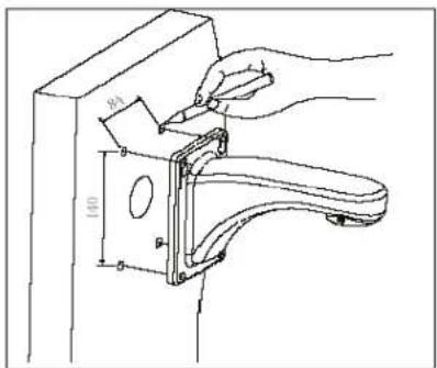
text_image
Technical diagram showing a hand using a tool to adjust or install a mechanical component, with dimension labels and part numbers.Fig 2
b. As shown in Fig 3, fix the wall hanging bracket on the wall with wire and cable through it.
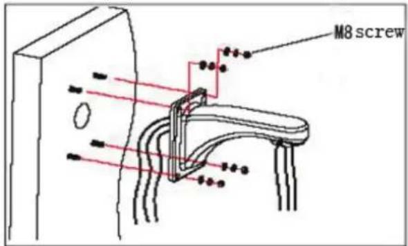
text_image
M8 screwFig 3
2.3.2 Corner Mounted (Optional)

natural_image
Technical line drawings of two security camera modules mounted on vertical posts (no text or symbols)Fig 4
Installation conditions:
Corner mounted dome can be used in a hard wall structure with an angle of 90^ whose thickness should be enough to install expansion bolts in indoor and outdoor environments. The wall must bear at least 4 times the weight of the dome. Install corner mounted attachment and wall hanging bracket:
a. As shown in Fig5, with the installation holes in the corner mounted attachment as pattern, draw locations on the wall with an angle of 90^ and drill to install expansion bolt.
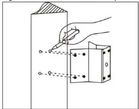
text_image
Technical diagram showing a hand using a pen to draw a rectangular component with holes, labeled with Chinese character 'O'Fig 5
b. As shown in Fig6, use M8 screw nut to fix the base of corner mounted on the wall with all cables through the center holes of the corner mounted, marine glue and bracket. Enough wiring length should be left.
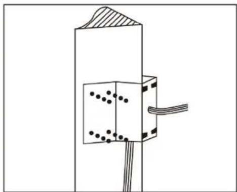
natural_image
Pure technical diagram of a mechanical or electrical component with no visible text, numbers, or symbolsFig 6
c. As shown in Fig7, fix the wall hanging bracket with all cables power through it on the corner mounted attachment.

natural_image
Technical diagram of a mechanical assembly with no visible text or symbolsFig 7
2.2.3 Pole Mounted (Optional)

natural_image
Technical line drawing of a security camera mounted on a vertical pole (no text or symbols)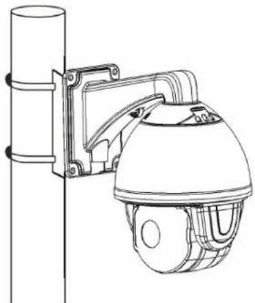
natural_image
Line drawing of a security camera mounted on a vertical pole (no text or symbols)Fig 8
Installation conditions:
Pole mounted domes can be used on a hard pole structure in indoor and outdoor environment whose diameter should match the installation size of stainless hose clamps. Factory default is 6 inches stainless hose clamps (fit 5"-6" polls). The pole structure can bear at least 4 times the weight of the dome. Install corner mounted attachment and wall hanging bracket: a. As shown in Fig 9, use the stainless hose clamps to attach the pole mounted attachment with all cable through it on the pole structure.
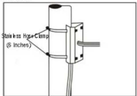
text_image
Stainless Hose Clamp (6 Inches)Fig 9
b. As shown in Fig 10, attach the wall hanging bracket with all cables through it on the pole mounted attachment.
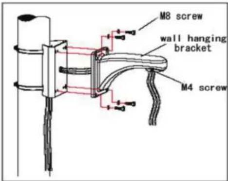
text_image
M8 screw wall hanging bracket M4 screwFig 10
2.3.4 Ceiling Mounted (Optional)

natural_image
Technical line drawing of two identical security camera modules (no text or symbols)Fig11
Installation conditions:
Ceiling mounted dome with thick pole can be used in the hard ceiling structure whose thickness should be enough to install expansion bolt in indoor and outdoor environment. The ceiling can bear at least 4 times the weight of the dome. Install the base of ceiling and boom:
a. As shown in Fig 12, with the installation holes in the base of ceiling as pattern, draw punched locations in the ceiling and punch to install M6 expansion bolt.
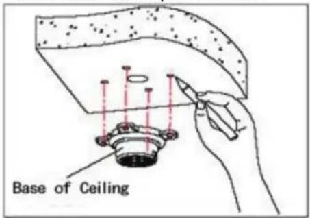
text_image
Base of CeilingFig 12
b. As shown in Fig 13, at first unscrew the M4 screw at the side of the base of ceiling and split the base of ceiling and boom. Then make the three groups of cables of power, video/control and alarming into the side recessing seal groove of the ceiling connector bottom and through the core hole of the base of ceiling mounted. Fix the base of hang ceiling on the ceiling board.
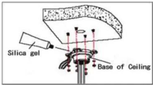
text_image
Silica gel Base of CeilingFig 13
Note: If the dome is used in the outdoor conditions, use the silica gel on the faying surface of the base of hang ceiling and the ceiling board and around the out-holes to be sure water proof
c. As shown in the Fig 14, tighten the boom with electrical wire and cable through it on the base of ceiling and screw up the M4 screw.
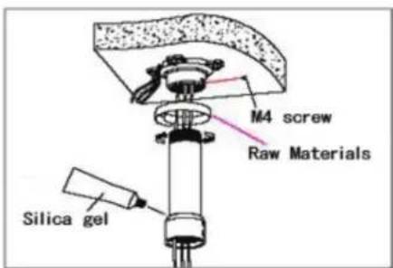
text_image
M4 screw Raw Materials Silica gelFig 14
Note: If the dome is used in the outdoor conditions, after using enough raw materials to wrap the thread at the upper end of boom, tighten the boom on the base of ceiling. Use the silica gel around the joint sleeve and connector of the boom to be sure water proof
2.4 CONNECTION
Connection of RS485
Before connecting, please remove the power and read carefully the instructions of all connected devices. (If the camera and the DVR support coaxial control, please ignore this step).

flowchart
graph TD
    A["12VDC Power Cable"] --> B["Connected to 12VDC Power"]
    B --> C["Monitor"]
    C --> D["Controller Keyboard"]
    D --> E["Connected to RS-485 A/B Terminal"]
    F["Monitor Cable"] --> C
    G["Communication Cable (Twisted Pair)"] --> D
Fig 24
3. FUNCTION INSTRUCTION
3.1 POWER UP ACTION
text_image
Power Up Self Testing
text_image
Pan, Tilt, Camera Self-test Completion
✿ Lens action: Lens zooms out to the widest angle.
✿ Pan action: Pan rotate in certain direction and stops at zero coordinates.
◇ Tilt action: Tilt rotate in certain direction and stops at zero coordinates.
✿ From running the action above to power up mode completion, power up self-testing finishes.
3.2 BASIC FUNCTION
Dome Running
Control joystick or up, down, left and right key on the keyboard.
Zoom
Press ZOOM- button for zooming out
Press ZOOM+ button for zooming in
Focus
Press FOCUS- button, use to focus near.
Press FOCUS+ button, use to focus far away.
Iris
Press IRIS- to close the iris and decrease the image brightness gradually.
Press IRIS+ to enlarge the iris and increase the image brightness gradually
Remark: Some preset points are occupied by special functions.
3.3 SWITCHING VIDEO SIGNAL
There are two methods to switch the video signal.
A) Call twice preset 102 to enter the Sub OSD menu:
- Press "Zoom+" or "Zoom-" to move the option to the item 1.
- Press the "Focus+" or "Focus-" to switch to the signal output needed, then press "zoom+ or Zoom- to the item 6" RETURN"
- Call 102 two times to exit from the Sub OSD menu.
B) Direct shortcut command. Please see the shortcut commands below for details.
Notes:
- Do not change the parameter of the Sub OSD menu randomly to avoid any unexpected issues.
- Makes sure to reboot the PTZ after switching the video signal output.
3.4 SHORTCUT COMMANDS
Below is list of shortcut commands, user can enable the function by shortcut command.
| Call PRESET | FUNCTION | Call PRESET | FUNCTION |
| 16 | OSD on/Call twice | 88 | Freeze on |
| 34 | Reset | 89 | Freeze off |
| 35 Wiper on | 92 A-B scan | ||
| 36 | Wiper off | 94 | OSD off |
| 75 | Pattern 1 | 95 | OSD on |
| 76 | Pattern 2 | 96 | Guard tour 3 |
| 77 | Pattern 3 | 97 | Guard tour 2 |
| 79 | Digital zoom on | 98 (38) | Guard tour 1 |
| 80 | Digital zoom off | 99 (39) | Pan scan |
| 81 (41) | Auto day/night | 137 (Twice) | Switch to AHD |
| 82 (42) | Switch to night | 138 (Twice) | Switch to TVI |
| 83 | Switch to day | 139 (Twice) | Switch to CVI |
| 84 | Force on far light | 140 (Twice) | Switch to CVBS |
| 85 | Force on near light | 115 (Twice) | Switch to NTSC |
| 86 | BLC on | 116 (Twice) | Switch to PAL |
| 87 | BLC off |
Remark: Some special functions probably can't be used because of the limit of protocol when the dome controlled by different devices.
Call preset 95 to enter the OSD, call preset 94 to exit the OSD.
✿ Up or Down: Move the option in the OSD, change the option in the OSD.
Right: Enter the option, select the item or confirm.
✨ Left: Return to main menu or cancel
✨ Angle Display: XXX.XX(pan)/XXX.XX(tilt)
✿ IR Display: Display on the lower right corner of the screen.
Remark: 1. Items with "< >" mean they have sub menu.
-
“-” means the cursor selecting some option.
-
When entering the setting page in menu, it is useful to call preset 94 to exit the menu directly. Such as the sub-menu
in menu .
4 OSD MENU
4.1 MENU INDEX
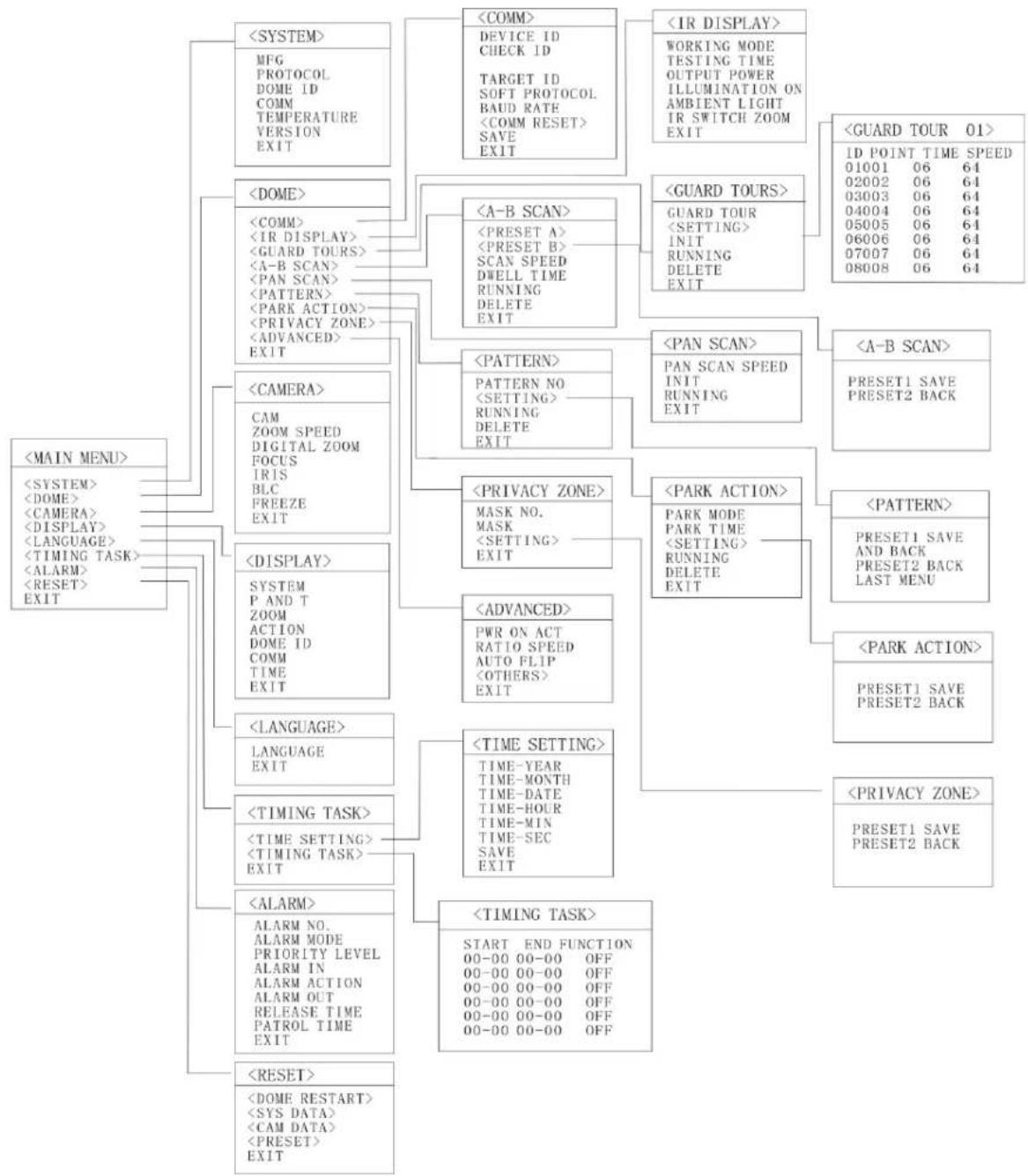
flowchart
graph TD
    A["<<MAIN MENU>>"] --> B["<<SYSTEM>>"]
    A --> C["<<DOME>>"]
    A --> D["<<CAMERA>>"]
    A --> E["<<DISPLAY>>"]
    A --> F["<<LANGUAGE>>"]
    A --> G["<<TIMING TASK>>"]
    A --> H["<<ALARM>>"]
    A --> I["<<RESET>>"]

    B --> J["<<COMM>>"]
    B --> K["<<IR DISPLAY>>"]
    B --> L["<<GUARD TOURS>>"]

    C --> M["<<A-B SCAN>>"]
    C --> N["<<PATTERN>>"]
    C --> O["<<PRIVACY ZONE>>"]

    D --> P["<<PAN SCAN>>"]
    D --> Q["<<PARK ACTION>>"]

    E --> R["<<PATENN>>"]
    E --> S["<<PARK ACTION>>"]

    F --> T["<<PWR ON ACT RATE TIME-YEAR OFF"]
    F --> U["<<TIME-SECS SAVE OFF"]

    G --> V["<<TIMING TASK>>"]

    H --> W["<<START END FUNCTION OFF"]

    I --> X["<<00-00 00-00 OFF"]

    J --> Y["<<DEVICE ID CHECK ID TARGET ID SOFT PROTOCOL BAUD RATE <COMM RESET> SAVE EXIT"]

    K --> Z["<<WORKING MODE TESTING TIME OUTPUT POWER ILLUMINATION ON AMBIENT LIGHT IR SWITCH ZOOM EXIT"]

    L --> AA["<<PRESET A> <PRESET B> SCAN SPEED DWELL TIME RUNNING DELETE EXIT"]

    M --> AB["<<PRESET NO <SETTING> RUNNING DELETE EXIT"]

    N --> AC["<<PAN SCAN SPEED INIT RUNNING EXIT"]

    O --> AD["<<PARK MODE PARK TIME <SETTING> RUNNING DELETE EXIT"]

    P --> AE["<<PARK ACTION>>"]

    Q --> AF["<<PARK ACTION>>"]

    R --> AG["<<PARK ACTION>>"]

    S --> AH["<<PARK ACTION>>"]

    T --> AI["<<TIME SETTING> TIME-MONTH TIME-DATE TIME-HOUR TIME-MIN TIME-SEC SAVE EXIT"]

    U --> AJ["<<TIME SETTING> TIME-YEAR TIME-MONTH TIME-DATE TIME-HOUR TIME-MIN TIME-SEC SAVE EXIT"]

    V --> AK["<<TIME SETTING> TIME-YEAR TIME-MONTH TIME-DATE TIME-HOUR TIME-MIN TIME-SEC SAVE EXIT"]

    W --> AL["<<TIME SETTING> TIME-YEAR TIME-MONTH TIME-DATE TIME-HOUR TIME-MIN TIME-SEC SAVE EXIT"]

    X --> AM["<<TIME SETTING> TIME-YEAR TIME-MONTH TIME-DATE TIME-HOUR TIME-MIN TIME-SEC SAVE EXIT"]

    Y --> AN["<<TIME SETTING> TIME-YEAR TIME-MONTH TIME-DATE TIME-HOUR TIME-MIN TIME-SEC SAVE EXIT"]

    Z --> AO["<<PARK ACTION>>"]

    AA --> AP["<<PARK ACTION>>"]

    AB --> AQ["<<PARK ACTION>>"]

    AC --> AR["<<PARK ACTION>>"]

    AD --> AS["<<PARK ACTION>>"]

    AE --> AT["<<PARK ACTION>>"]

    AF --> AU["<<PARK ACTION>>"]

    AG --> AV["<<PARK ACTION>>"]

    AH --> AW["<<PARK ACTION>>"]

    AI --> AX["<<PARK ACTION>>"]

    AJ --> AY["<<PARK ACTION>>"]

    AK --> AZ["<<PARK ACTION>>"]

    AL --> BA["<<PARK ACTION>>"]

    AM --> BB["<<PARK ACTION>>"]

    AN --> BC["<<PARK ACTION>>"]

    AO --> BD["<<PARK ACTION>>"]

    AP --> BE["<<PARK ACTION>>"]

    AQ --> BF["<<PARK ACTION>>"]

    AR --> BG["<<PARK ACTION>>"]
4.2 SYSTEM INFORMATION
| <MAIN MENU> |
| <SYSTEM> |
| <DOME> |
| <CAMERA> |
| <DISPLAY> |
| <LANGUAGE> |
| <TIMING TASK> |
| <ALARM> |
| <RESET> |
| EXIT |
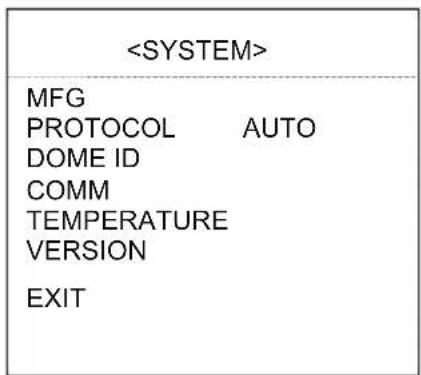
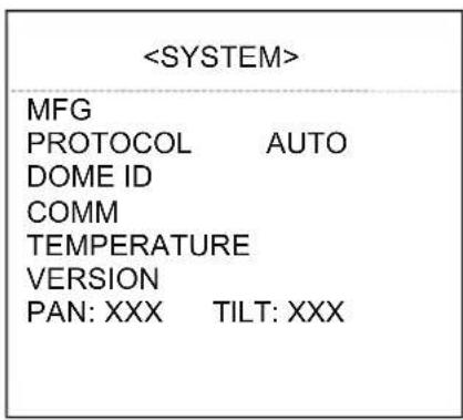
When enter the OSD, it display
| MFG | |
| PROTOCOL | PELCO D-P |
| DOME ID | |
| 001 | |
| COMM | 2400.N.8.1 |
| TEMPERATURE | 41.8°C |
| VERSION | V863R15122109 |
| EXIT | |
Enter to the SYSTEM, you will see:
MFG: Max 15 characters displayed on the screen.
PROTOCOL: Display the protocol of the dome
DOME ID: Display the dome address
COMM: Baud rate.
TEMPERATURE: Display the temperature of the camera, it changes along with the temperature of the camera, the data is unchangeable manually.
VERSION: Version will update along with the product upgrading
Remark: Protocol, ID and COMM all can be set in menu
4.3 DOME
| <DOME> |
| <COMM> |
| <IR DISPLAY> |
| <GUARD TOURS> |
| <A-B SCAN> |
| <PAN SCAN> |
| <PATTERN> |
| <PARK ACTION > |
| <PRIVACY ZONE> |
| <ADVANCED> |
| EXIT |
4.3.1 Communication
| <COMM> | |
| DEVICE ID | 125295 |
| CHECK ID | 125288 |
| TARGET ID | 000 |
| SOFT PROTOCOL AUTO | |
| BAUD RATE | 2400 |
| <COMM RESET> | |
| SAVE | |
| EXIT | |
Fig4.3.1.1

text_image
Fig.4.3.1.2
DEVICE ID: It is auto generated by system.
CHECK ID: To change the TARGET ID, please input the CHECK ID exactly same as the DEVICE ID displays on the screen.
TARGET ID: Target ID is available from 001 to 250 and used to distinguish several domes of same ID.
SOFT PROTOCOL: Soft protocol is auto, Pelco-D and Pelco-P available
BAUD RATE: 1200BPS, 2400BPS, 4800BPS, 9600BPS available
SAVE: After saving, the dome will reboot. Communication settings take effect.
4.3.2 IR Display
| WORKING MODE | |
| AUTO | |
| TESTING TIME | |
| 08S | |
| OUTPUT POWER | 100% |
| ILLUMINATION ON | 03 |
| AMBIENT LIGHT | 09 |
| IR SWITCH ZOOM | 06 |
WORKING MODE: Working mode has auto, black/white, color selectable. Default is auto.
TESTING TIME: On IR auto working mode and the programmed time, the IR will execute programmed action accordingly, e.g. Switch from day to night or from night to day. The detection time is from 2s to 15s selectable.
OUTPUT POWER: Output power has 40%, 60%, 80%, 100% for selection!
ILLUMINATION ON: Illumination on is 1 to 15 grade selectable and default is 3. On the auto IR
working mode, if the illumination on level is less than the ambient light, the picture will change to color, the IR illumination will turn off automatically. If the illumination on level is more than the ambient light, the picture will change to black & white, the IR illumination will turn on automatically.
AMBIENT LIGHT: Ambient light is a system data. User can not change it manually. It changes according to the environment all the time. The data will refresh every time when user enter the OSD. It is from 0 to 50 grade.
IR SWITCH ZOOM: When zoom value reaches to the demanded setting, the IR LEDs with auto switch from near illumination to far illumination, zoom value option from 01-10.
4.3.3 Guard Tours
| GUARD TOUR01<SETTING>INITRUNNINGDELETEEXIT |
| ID | POINT | TIME(S) | SPEED |
| 1 | 01 | 06 | 64 |
| 2 | 02 | 06 | 64 |
| 3 | 03 | 06 | 64 |
| 4 | 04 | 06 | 64 |
| 5 | 05 | 06 | 64 |
| 6 | 06 | 06 | 64 |
| 7 | 07 | 06 | 64 |
| 8 | 08 | 06 | 64 |
GUARD TOUR: Total 8 guard tours selectable.
SETTING: Each guard tour includes max 16 presets. The number of the preset is from 0-64, but 0 is not valid. Dwell time is 1 to 60s selectable. Speed is 1 to 64 selectable.
INIT: After initial, preset point, dwell time and speed will resume to default setting.
RUNNING: Running the present guard tour.
DELETE: Delete the guard tour set. After deleting, the present preset points in the guard tours all display as 0. While the exact preset point information won't be deleted. So it is convenient for user to select the preset point needing to be in guarded tour.
4.3.4 A-B Scan
| PRESET A | 01 |
| PRESET B | 02 |
| SCAN SPEED | 20 |
| DWELL TIME | 06S |
| RUNNING | |
| DELETE | |
| EXIT | |
Fig4.3.4.1
| A-B SCAN |
| RUNNING.... |
Fig 4.3.4.2
PRESET A: On A-B scan, A point can be any preset
PRESET B: On A-B scan, B point can be any preset.
SCAN SPEED: A-B scan speed is 1 to 64 selectable.
DWELL TIME: Dwell time between A to B is 2s to 60s selectable.
RUNNING: Running the A-B scan. Check Fig. 4.3.4.2.
DELETE: After deleted, the preset points of A and B display as 0. While the exact preset point information won't be deleted. So it is convenient for user to select the preset point needing to be scanned. Speed and dwell time will reset as default setting
4.3.5 Pan Scan
| PAN SCAN SPEED 20 INITRUNNINGEXIT |
| PAN SCAN |
| RUNNING... |
PAN SCAN SPEED: Pan scan speed is 1 to 64 selectable.
INIT: Reset the scan speed and tilt degree as default setting.
RUNNING: Running the scan speed and tilt degree set.
4.3.6 Pattern
| PATTERN NO | OFF |
| RUNNING | |
| DELETE | |
| EXIT | |
| <PATTERN> |
| PRESET 1 SAVE |
| PRESET 2 BACK |
4.3.7 Park Action
| PARK MODE | OFF |
| PARK TIME | 01M |
| CALL | |
| DELETE | |
| EXIT | |
| PRESET 1: SAVEPRESET 2: BACK |
4.3.7.1
4.3.7.2
PARK MODE: Park mode includes OFF, Park action, A-B scan, Pan scan, guard tour 01, pattern 1.
When park mode is OFF status, the dome doesn't run park mode.
Example: Running A-B scan at first, when the action stops unexpectedly, it enters the park mode to continue to run A-B scan.
PARK TIME: Park time is 01\~60 Min's selectable.
SETTING: After entering the OSD menu, as 4.3.7.2, move to the desired position and save the settings.
CALL: Call the park action, if there is no setting, system will remind you that "Please set park action".
DELETE: Delete the settings.
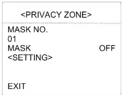
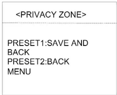
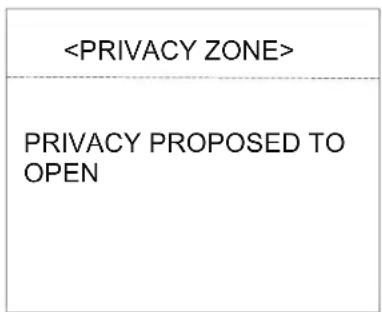
4.3.8 Privacy Zone(Optional)
text_image
4.3.8.1
text_image
4.3.8.2
text_image
4.3.8.3
MASK NO.: Mask No. depends on the number of the module supported.
MASK: Mask has on and off selectable.
SETTING: Set the specific parameter of present mask NO. And call preset 1 to save the settings.
Direction operation—Modify the coordinate of dome
Zoom operation—Modify the size of scenery
Iris operation—Modify the size of privacy zone
Remark: The mask size is better than double the target size. If needing to modify mask NO.02, set it again. If needing to stop it, set mask to OFF status.
If the module doesn't support privacy mask, the screen will display the interface as Fig. 4.3.8.3.
4.3.9 Advanced
PWR ON ACT: Power on action can be set as Memory, A-B scan, Pan scan, Park action, Pattern 1 and No action, Guard tour 1.
RATIO SPEED: Ratio speed can be set as ON or OFF status.
AUTO FLIP: Auto flip can be set as ON or OFF status.
WIPER MODE: WIPER MODE is On or Off status.
WIPER SPEED: Wiper speed 1 -5 level adjustable
WIPER TIME: Wiper time 1-5 times adjustable
4.4 CAMERA
| CAM | AUTO |
| ZOOM SPEED | QUICK |
| DIGITAL ZOOM | OFF |
| FOCUS | AUTO |
| IRIS | AUTO |
| BLC | OFF |
| FREEZE | OFF |
| EXIT | |
CAM: Display the information of module supported by this dome.
ZOOM SPEED: Zoom speed is quick and slow selectable.
DIGITAL ZOOM: Digital zoom is on/off selectable.
FOCUS: Focus is auto and manual selectable
IRIS: Iris is auto and manual selectable
BLC: BLC is ON and OFF selectable
FREEZE: Video freeze is ON and OFF selectable
Remark: Only if those functions are available on the present module, the user can use them.
4.5 DISPLAY
| P AND T | ON | |
| ZOOM | ON | |
| ACTION | ON | |
| DOME ID | ON | |
| COMM | ON | |
| TIME | OFF | |
| EXIT | ||
P AND T: On screen, it displays the pan and tilt degree, user can enable or disable it.
ZOOM: Displays the zoom level.
ACTION: On the screen, it displays the current action, such as A-B scan, Call preset, Save preset, Call park action, Pan scan etc. User can enable or disable it
DOME ID: At the top left corner of screen, it displays the dome ID. User can enable or disable it.
COMM: At the top left corner of screen, it displays the dome communication information. User can enable or disable it.
TIME: Displays the current time on screen.
4.6 LANGUAGE
| LANGUAGE | ENGLISH |
| EXIT | |
LANGUAGE: Language can be set as English, Espanola, French, Portuguese, Polish, Deutsch, Italian. Default language is English.
4.7 TIMING TASK
| START END FUNCTION | ||
| -00 00 - 00 00 | OFF | |
| 00 00- 00 00 | OFF | |
| 00 00- 00 00 | OFF | |
| 00 00- 00 00 | OFF | |
| 00 00- 00 00 | OFF | |
| 00 00- 00 00 | OFF | |
| EXIT | ||
| TIME-YEAR | 2016 |
| TIME-MONTH | 01 |
| TIME-DATE | 06 |
| TIME-HOUR | 15 |
| TIME-MIN | 34 |
| TIME-SEC | 56 |
| SAVE | |
| EXIT | |
4.9 RESET
| CONFIRM: SAVE DATA,DOME RESTART | |
| OK | |
| CONFIRM: FACTORY DEFAULTOK | CONFIRM: FACTORY DEFAULTOK |
CONFIRM: Delete the presets information saved by the dome.
5. AUTO TEMPERATURE CONTROL
This product has built-in fan and heater, which accordingly cool or heat through temperature sensitive circuit inside the dome.

TRANSCENDENT
VITEK
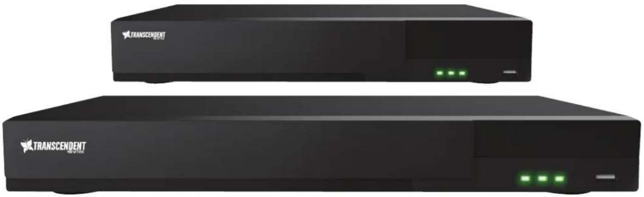
CONSIDER THESE OTHER GREAT TRANSCENDENT PRODUCTS!
natural_image
Exterior view of two black rectangular electronic devices with green indicator lights (no visible text or symbols)VT-TTAR Series
Transcendent Series 4, 8, and 16 Channel HD-TVI/AHD/960H/IP Digital Video Recorders

FEATURES
• 4, 8, or 16 Channel HD-TVI/AHD/960H BNC Inputs + IP Camera Support
• 1-Channel IP Camera Support (VT-TTAR410 / VT-TTAR810) / 4-Channel IP Camera Support (VT-TTAR1620)
- Simple plug and play, point-to-point connection from camera to DVR
• H.264 Compression
• HDMI, VGA, and BNC (Spot) Video Outputs
• 2-Way Audio
• PTZ Control over RS-485
• 4 Alarm inputs / 1 Alarm Output
- Pentaplex: Live Display / Record / Playback / Backup / Remote Access
- 1 Internal SATA2/SATA3 HDD Slot supporting up to 6TB (VT-TTAR410 / VT-TTAR810) / 2 Internal SATA2/SATA3 HDD Slots supporting up to 12TB (VT-TTAR1620)
• Applications for iOS & Android
- Remote Viewing over the Internet via Web Browser or LAN
• Mac OS® Client & CMS Central Management Software Included
• Supports both Dynamic and Static IP Addresses
• Control locally via USB Mouse or IR Remote control
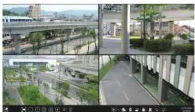
natural_image
Composite image showing urban infrastructure including elevated highways, green spaces, and a paved road (no visible text or symbols)Remote Viewing with Web Browsers

text_image
Screenshot of a video editing software interface displaying three video thumbnails with urban and commercial scenes, likely from an old video or video editing tool.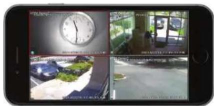
text_image
Smartphone screenshot displaying surveillance camera feeds with time, clock, car, and building photosRemote Viewing Using Mac OSXLocal MpageAvea1VieEongPhteDefRead, & Android Devices
| VT-TPTZ10HR-2A4 Specifications | VT-TPTZ10HR-2A4 | VT-TPTZ10HRC-2A4 | VT-TPTZ10HRF-2A4 |
| Sensor | 1/3" 2.1 MegaPixel CMOS Sensor | ||
| Resolution | 1080P (1920x1080) | ||
| Video Output Interface | 4-IN-1: HD-TVI / AHD / CVI / CVBS | ||
| LEDs | 6 Integrated High Power IR LEDs (850nm) | ||
| IR distance | Up to 165' IR Range | ||
| Ambient Light Detection | 1-15 grades selectable (with IR illumination on) | ||
| Lens | 5mm to 50mm Lens offering 10x Optical Zoom | ||
| Min. illumination | Color: 0.1Lux \ B/W: 0.01Lux (IR Off) / 0 Lux (IR On) | ||
| Day/Night Operation | True Day/Night by IR Cut Filter | ||
| Digital Noise Reduction | 2D-DNR | ||
| Pan range | 360°continuous rotation | ||
| Tilt range | 0°~93° auto flip 180° | ||
| Manual Pan speed | 0.02~480°/S | ||
| Manual Tilt speed | 0.02~160°/S | ||
| Preset Points | 220 | ||
| Go to Preset speed | Adjustable 1-64 | ||
| 360°Scan | Adjustable 1-64 | ||
| A-B Scan | User programmable | ||
| A-B Scan speed | Adjustable 1-64 | ||
| Dwell Preset | Adjustable 1-60s interval | ||
| Pattern Scan | 4 groups | ||
| Guard Tours | 8 groups | ||
| Guard Points | Max.16 points, dwell time user selectable | ||
| Time Scheduling Function | 6 tasks | ||
| PWR On Action | Memory/Pattern 1/Tour 1/360° scan/A-B scan/Park 1/None | ||
| Park Mode | Pattern 1/Tour 1/360° scan/A-B scan/Park 1/None | ||
| Communication Protocol | Pelco-D,Pelco-P | ||
| Baud Rate | 2400bps as default | ||
| Communication | RS485 (+/-) / COC (Control Over Coax) | ||
| Weather Resistance | IP66 | ||
| Operation Temperature | -40°F ~ 140°F (-40°C ~ 60°C) with included outdoor housing | ||
| Input Voltage | 12VDC | ||
| Power Consumption | < 25W | ||
| Lightning Protection | Transient voltage 6000V | ||
| Dimensions (WxHxD) | 5.5" x 9.5" x 9.5" 7.5" x 7.5" x 9" | 5.5" x 5.5" x 14.5" | |
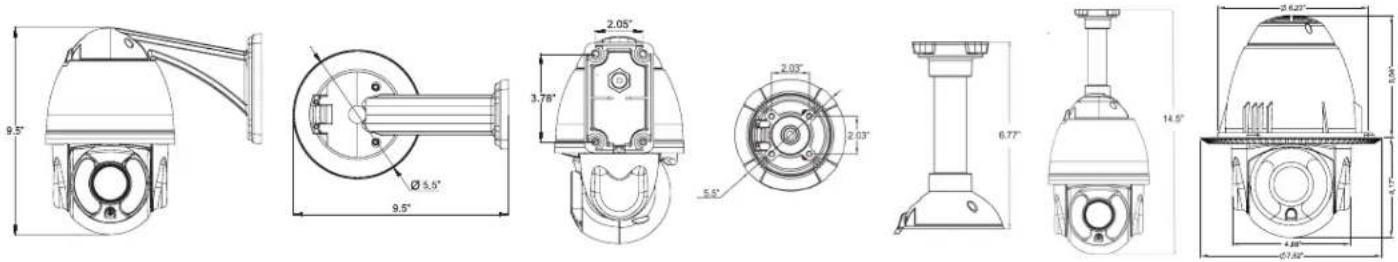
text_image
Technical drawings of a security camera module with dimensional annotations in inches and degreesVT-TPTZ36HR-2A4 Specifications
| Sensor | 1/3" 2.1 MegaPixel CMOS Sensor |
| Resolution | 1080P (1920x1080) |
| Video Output Interface | 4-IN-1: HD-TVI / AHD / CVI / CVBS |
| LEDs | 8 Integrated High Power IR LEDs (850nm) |
| IR distance | Up to 500' IR Range |
| Ambient Light Detection | 1-15 grades selectable (with IR illumination on) |
| Lens | 4.6mm to 152mm Lens offering 36x Optical Zoom |
| Min. illumination | Color: 0.1Lux \ B/W: 0.01Lux (IR Off) / O Lux (IR On) |
| Day/Night Operation | True Day/Night by IR Cut Filter |
| Digital Noise Reduction | 2D-DNR |
| Pan range | 360°continuous rotation |
| Tilt range | 0°~93° auto flip 180° |
| Manual Pan speed | 0.02~480°/S |
| Manual Tilt speed | 0.02~160°/S |
| Preset Points | 220 |
| Go to Preset speed | Adjustable 1-64 |
| 360°Scan | Adjustable 1-64 |
| A-B Scan | User programmable |
| A-B Scan speed | Adjustable 1-64 |
| Dwell Preset | Adjustable 1-60s interval |
| Pattern Scan | 4 groups |
| Guard Tours | 8 groups |
| Guard Points | Max.16 points, dwell time user selectable |
| Time Scheduling Function | 6 tasks |
| PWR On Action | Memory/Pattern 1/Tour 1/360° scan/A-B scan/Park 1/None |
| Park Mode | Pattern 1/Tour 1/360° scan/A-B scan/Park 1/None |
| Communication Protocol | Pelco-D,Pelco-P |
| Baud Rate | 2400bps as default |
| Communication | RS485 (+/-) / COC (Control Over Coax) |
| Weather Resistance | IP66 |
| Operation Temperature | -40°F ~ 140°F (-40°C ~ 60°C) with included outdoor housing |
| Input Voltage | 12VDC |
| Power Consumption | < 25W |
| Lightning Protection | Transient voltage 6000V |
| Dimensions | 13.78" (H) x 8.46" (Dia) |

VITEK LIMITED PRODUCT WARRANTY
VITEK products carry a three (3) year limited warranty. Digital recording and storage products are also warranted for 3 years. * Per a special agreement with Western Digital, as of August 2016, VITEK also warrants factory installed Hard Drives for the full 3 year span of the recorder warranty provided that the recorder was purchased through an authorized VITEK distributor.
VITEK warrants to the purchaser that products manufactured by VITEK are free of any rightful claim of infringement or the like, and when used in the manner intended, will be free of defects in materials and workmanship for a period of three (3) years, or as otherwise stated above, from the date of purchase by the end user. This warranty is non-transferable and extends only to the original buyer or end user customer of a Vitek Authorized Reseller.
This warranty shall not apply to repairs or replacements necessitated by any cause beyond the control of VITEK, including but not limited to, acts of nature, improper installation, excess moisture, misuse, lack of proper maintenance, accident, voltage fluctuations, or any unauthorized tampering, repairs or modifications. This warranty becomes VOID in the event of alteration, defacement, or removal of serial numbers.
Within the first 6 months of purchase, VITEK will replace or credit any defective product returned at the request of the customer (subject to availability) with a new product that equals or exceeds the performance of the original product purchased.
Within the first 6 months of purchase, at its sole discretion, VITEK may issue an advance replacement for a defective product; however, all related costs including, but not limited to shipping and/or delivery charges will be the responsibility of the customer. If upon return inspection a product is determined to be in good working order or shows evidence of misuse, the customer will be responsible for full payment of the original product purchased as well as the replacement product.
Beyond the first 6 month period for the remainder of the warranty, VITEK'S responsibility shall be limited to repairing the defective product, including all necessary parts and related labor costs. At its sole discretion, VITEK may choose to either exchange a defective product or issue a merchandise credit towards future product purchases. Any replacement parts furnished in connection with this warranty shall be warranted for a period not to exceed the remaining balance of the original equipment warranty.
A Return Authorization number or "RA" number must be obtained prior to the return of any item for repair, replacement, or credit. VITEK requires that this "RA" number be clearly printed on the outside of the shipping carton to avoid refusal of said shipment. The Return Authorization number expires after 30 days. Products returned after the 30 day period will be subject to refusal. Shipping charges, if any, must be prepaid. A copy of the bill of sale (or invoice of purchase), together with a complete written explanation of the problem must accompany all returns.
Vitek makes no warranty or guarantee whatsoever with respect to products sold or purchased through unauthorized sales channels. Warranty support is available only if product is purchased through a Vitek Authorized Reseller.
*Limited Warranty means that VITEK reserves the right to repair or replace any product found defective within the warranty time period, prorated to the date of original purchase. If VITEK cannot repair the product, VITEK reserves the right to replace it with an equal or better product and grade at VITEK's discretion.