Stealthbox SB-POL-SLINGSUBD/10W3v3-4 - Subwoofer JL Audio - Free user manual and instructions
Find the device manual for free Stealthbox SB-POL-SLINGSUBD/10W3v3-4 JL Audio in PDF.

User questions about Stealthbox SB-POL-SLINGSUBD/10W3v3-4 JL Audio
0 question about this device. Answer the ones you know or ask your own.
Ask a new question about this device
Download the instructions for your Subwoofer in PDF format for free! Find your manual Stealthbox SB-POL-SLINGSUBD/10W3v3-4 - JL Audio and take your electronic device back in hand. On this page are published all the documents necessary for the use of your device. Stealthbox SB-POL-SLINGSUBD/10W3v3-4 by JL Audio.
USER MANUAL Stealthbox SB-POL-SLINGSUBD/10W3v3-4 JL Audio
natural_image
Black plastic mechanical component with a circular opening and side grooves (no text or symbols visible)Stealthbox®
INSTALLATION GUIDE
for the
SB-POL-SLINGSUBD/10W3v3-4
SB-POL-SLINGSUBD/10W3v3-2
SKU# 94637 (4 Ω) & 94638 (2 Ω)
2015-Up Polaris Slingshot
Enclosure Type: Sealed
Driver Type: 10W3v3
Nominal Impedance: 4 or 2 ohms
Continuous Power Handling: 500 watts (RMS method)
SB-POL-SLINGSUBD/10W3v3 INSTR_SKU# 011482
! IMPORTANT
If you choose to perform the installation yourself, it is absolutely vital that the Stealthbox® be properly mounted to the vehicle according to these instructions. Failure to mount the enclosure properly presents two problems:
1) The sub-bass performance will suffer due to the movement of the enclosure caused by the force exerted by the woofer(s).
2) A loose enclosure presents a serious safety hazard in the event of a collision or sudden deceleration.
INSTALLATION DIFFICULTY:

ESTIMATED TIME: 1 HOUR

text_image
JL AUDIO - Quality & Design - SBX STEALTHBOX®Thank you for choosing a JL Audio Stealthbox* for your automotive sound system. With proper installation, your new vehicle-specific enclosed subwoofer system will deliver years of listening pleasure.
We strongly recommend that you have your new Stealthbox® installed by your authorized JL Audio dealer. The installation professionals employed by your dealer have the necessary tools and experience to disassemble and reassemble your vehicle properly. If you prefer to perform your own installation, please read this installation guide completely before beginning the process.
INCLUDED HARDWARE

text_image
Technical diagram of a mechanical assembly with numbered components and a legend for screw partsBOM ID Qty SKU Description
| 1 2 153814 | 8 - 32 x 1/2" Pan Head Phillips Machine Screw | |
| 2 1 153850 | ABS Plate | |
| 3 2 153855 | M6 + 1 x 50mm | Hex Drive Flanged Button 1Head Screw |
| 4 4 153858 | Nylon Plastic Washer | |
| 5 2 153853 | M6 + 1 x 25mm | Hex Drive Flanged Button Head Screw |
| 6 4 153856 | M6 + 1 U-Nut | |
| 7 1 153848 | Bottom Bracket | |
| 8 1 150285 | Nylon Cable Tie | |
| 9 1 153847 | Top Bracket | |
| - 1 153857 | 3/4" x 3/4" EPDM Foam (not shown) | |
| - 1 150249 | Foam Tape (not shown) | |
Note: For optimum performance, JL Audio recommends applying the included Foam Strips (or sound damping material) to surrounding plastic panels to reduce unwanted vibrations.
POWER RECOMMENDATION
JL Audio recommends high quality amplifiers such as the JL Audio MX500/1. The diagram below shows the recommended crossover settings for the MX500/1. For a detailed description of the amplifier settings, consult the owner's manual for the amplifier. If another amplifier is being used, please reference this illustration and use similar settings on that amplifier.
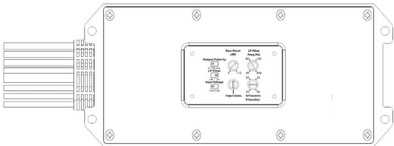
text_image
Output Polarity 0.185 cpe. LP Filter OFF / On Input Voltage Lock/High Input Sens. Infrasonic Filter(Hz) Bass Boost (dB) LP Filter Freq.(Hz) 80 130 40 400 30 35 20 40 Infrasonic Filter(Hz)CONNECTIONS
Using quality power, signal, and speaker wire is essential in ensuring the performance of your Stealthbox*. JL Audio recommends using a 4 AWG power kit such as the XD-PCS4-1B for your Stealthbox® amplifier. Other kits are available should you be using more than one amplifier. Signal wire such as the JL Audio Premium Audio Interconnect Cables should be used to provide signal for both channels of the amplifier. JL Audio recommends using 12 AWG speaker wire for subwoofers such as our XC-BCS12-25.
natural_image
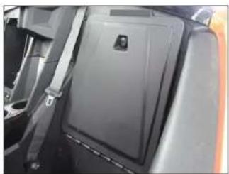
Interior view of a car seatbelt with a black plastic cover and a small emblem on the lid (no visible text or symbols)STEP 1
Slide the seat forward.
natural_image
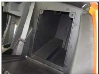
Interior view of a vehicle showing a rectangular opening with a dark plastic panel and mounting brackets (no visible text or symbols)STEP 2
Open the storage compartment, and remove the compartment door.
natural_image
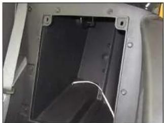
Close-up of a mechanical component with a dark rectangular opening and mounting holes (no visible text or symbols)STEP 3
Route speaker cable into the storage compartment.
natural_image
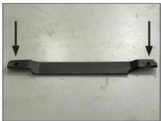
Metal mechanical component with two downward arrows pointing to its ends (no text or symbols visible)STEP 4
Slide an M6 - 1 U-Nut over each of the outer holes in the Bottom Bracket, as shown. Be sure the U-Nuts are oriented outward.
Page 4 • JL Audio, Inc., 2017 Continued on Next Page
SB-POL-SLINGSUBD/10W3v3 INSTR_SKU# 011482

natural_image
Close-up of a black electronic device with a white cable and control buttons (no visible text or symbols)STEP 5
Position the Bottom Bracket assembly behind the hinge, under the storage compartment, as shown. The center, flat section of the Bottom Bracket should be placed against the rear plastic panel. Center the Bottom Bracket below the storage compartment opening.
natural_image
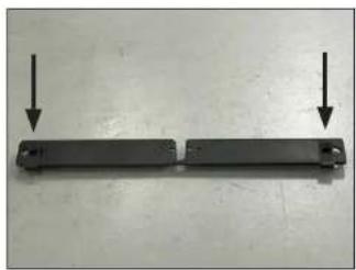
Two black rectangular objects with downward arrows pointing to each, placed horizontally on a plain surface (no text or symbols visible)STEP 6
Slide an M6 - 1 U-Nut over each of the outer holes in the Top Bracket, as shown. Be sure the U-Nuts are oriented downward.

natural_image
Close-up of a hand using a tool to adjust or install a component, no visible text or symbolsSTEP 7
Position the Top Bracket assembly behind the rear plastic panel, with its center cutout around the compartment latch, as shown. Position the ABS Plate between the Top Bracket and the compartment latch, aligning the holes in both parts.
Secure with a pair of 8 - 32 x 1/2" Pan Head Phillips Machine Screws, as shown.
natural_image
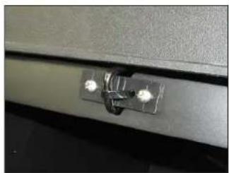
Close-up of a metallic bracket with two screws attached (no text or symbols visible)STEP 8
From inside the storage compartment, pass the Nylon Cable Tie through one of the inner holes in the Top Bracket and ABS Plate, around the front of the compartment latch, and back through the opposite inner hole in the ABS Plate and Top Bracket, into the storage compartment, as shown.
natural_image
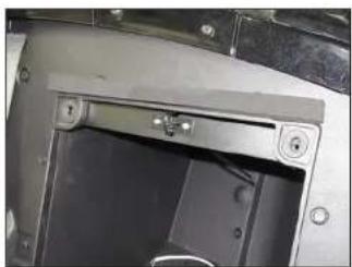
Close-up of a mechanical component with mounting holes and a central lock (no visible text or symbols)STEP 9
With the Top Bracket in the horizontal position, fully tighten the Nylon Cable Tie so that each of the M6-1 U-Nuts on the Top Bracket is aligned with the factory holes in the rear plastic panel.
Remove the adhesive backing from the 3/4" x 3/4" EPDM Foam, and attach the foam to the rear panel, above the storage compartment opening, as shown.
natural_image
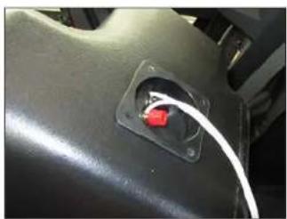
Close-up of a black mechanical component with a red socket and white cable inserted (no visible text or symbols)STEP 10
Connect the speaker cable to the terminal cup on the back of the enclosure, and slide the Stealthbox ^4 into the storage compartment.

natural_image
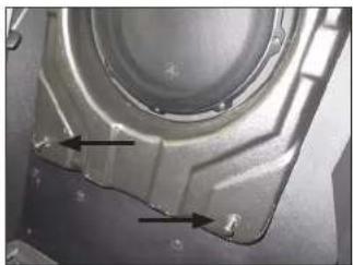
Close-up of a mechanical component with two arrows pointing to internal features (no visible text or symbols)STEP 11
Slide a 1/4" Nylon Plastic Washer over each of the two M6 - 1 x 50mm Hex Drive Flanged Button Head Screws. Pass an assembly through each of the holes in the top of the enclosure, and thread it into the M6 - 1 U-Nut.
Do not fully tighten at this time.
natural_image
Close-up of a mechanical component with two arrows pointing to features, no visible text or symbolsSTEP 12
Slide a 1/4" Nylon Plastic Washer over each of the two M6 - 1 x 25mm Hex Drive Flanged Button Head Screws. Pass an assembly through each of the holes in the bottom of the enclosure, and thread it into the M6 - 1 U-Nut.
Do not fully tighten at this time.
Page 5 • J. Audio, Inc., 2017 Continued on Next Page
SB-POL-SLINGSUBD/10W3v3 INSTR_SKU# 011482
natural_image
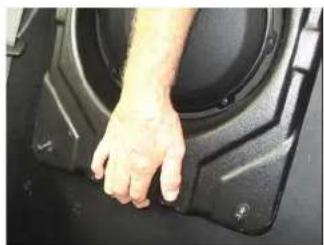
Close-up of a hand pressing down on a black plastic component (no visible text or symbols)STEP 13
Lift up on the enclosure, and fully tighten both M6 - 1 x 50mm Hex Drive Flanged Button Head Screws and both M6 - 1 x 25mm Hex Drive Flanged Button Head Screws.

natural_image
Close-up of a mechanical component with a circular housing and mounting brackets (no visible text or symbols)STEP 14
Pictured is the Stealthbox fully installed.
Slide the seat back.
Note: For optimum performance, we recommend applying the included Foam Strips (or sound damping material) to surrounding plastic panels to reduce unwanted vibrations.
SB-POL-SLINGSUBD/10W3v3 INSTR_SKU# 011482
CONGRATULATIONS!
You have completed the installation for this model! Enjoy your new Stealthbox ^® !

natural_image
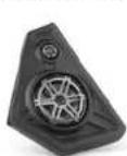
Interior view of a modern sports car with black leather seats and orange racing suit (no visible text or symbols)MID/HIGH FREQUENCY DRIVER FITMENT
SB-POL-SLINGSPKRS/M770 speaker pods are also available for your vehicle. Each weatherproof pod is designed for a perfect fit and houses a premium JL Audio component system.
SB-POL-SLINGSPKR/M770
SKU#
94636
JLAUDIO. How we play.
(954) 443-1100
www.jlaudio.com
All cases are subject to charge in their range, 3. Audio® and the 3. Audio logo, "Small" box, and the Smallbox logo and "Two we play" are required transformation of 3. Audio, Inc. "Shared of the Cloud" and Microphone logo on markets of 3. Audio, Inc. Filed in USA - 2017. Audio Inc. = Formar digital information projects via www.audio.com.
JLA-SKU# 011482 • ver. 05.23.2017 • 10369 NORTH COMMERCE PARKWAY • MIRAMAR, FLORIDA • 23025 • USA