Stealthbox SB-Y-YXZ1/10TW3 - Subwoofer JL Audio - Free user manual and instructions
Find the device manual for free Stealthbox SB-Y-YXZ1/10TW3 JL Audio in PDF.

User questions about Stealthbox SB-Y-YXZ1/10TW3 JL Audio
0 question about this device. Answer the ones you know or ask your own.
Ask a new question about this device
Download the instructions for your Subwoofer in PDF format for free! Find your manual Stealthbox SB-Y-YXZ1/10TW3 - JL Audio and take your electronic device back in hand. On this page are published all the documents necessary for the use of your device. Stealthbox SB-Y-YXZ1/10TW3 by JL Audio.
USER MANUAL Stealthbox SB-Y-YXZ1/10TW3 JL Audio
natural_image
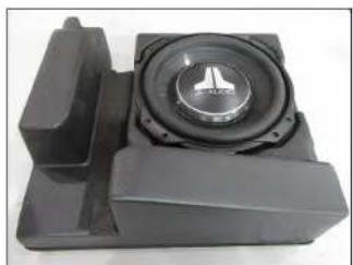
Close-up of a black audio component with a speaker grille and logo (no visible text or symbols)Stealthbox®
INSTALLATION GUIDE for the
SB-Y-YXZ1/10TW3
SKU# 94642
2016 & Up Yamaha YXZ1000R
Enclosure Type: Sealed
Driver Type: 10TW3-D4
Nominal Impedance: 2 ohms
Continuous Power Handling: 400 watts (RMS method)
SB-Y-YXZ1/10TW3 INSTR_SKU#011479
! IMPORTANT
If you choose to perform the installation yourself, it is absolutely vital that the Stealthbox ^* be properly mounted to the vehicle according to these instructions. Failure to mount the enclosure properly presents two problems:
1) The sub-bass performance will suffer due to the movement of the enclosure caused by the force exerted by the woofer(s).
2) A loose enclosure presents a serious safety hazard in the event of a collision or sudden deceleration.
INSTALLATION DIFFICULTY:

ESTIMATED TIME: 2-3 HOURS

text_image
JL AUDIO ~ Quality & Design ~ SBX STEALTHBOX®Thank you for choosing a JL Audio Stealthbox* for your automotive sound system. With proper installation, your new vehicle-specific enclosed subwoofer system will deliver years of listening pleasure.
We strongly recommend that you have your new Stealthbox® installed by your authorized JL Audio dealer. The installation professionals employed by your dealer have the necessary tools and experience to disassemble and reassemble your vehicle properly. If you prefer to perform your own installation, please read this installation guide completely before beginning the process.
SB-Y-YXZ1/10TW3 INSTR_SKU#011479
INCLUDED HARDWARE
BOM ID Qty SKU Description
| 1 8 153729 | 1/4 - 20 x 1" Serrated Flange Bolt | |
| 2 2 153876 | Bracket | |
| 3 4 153739 | 1/4" Serrated Spring Lock Washer | |
| 4 4 153740 | 1/4 - 20 Hex Nut | |
| 5 1 152330 | Template Front | |
| 6 1 152331 | Template Rear | |
| - 1 150249 | Foam Tape (not shown) | |

text_image
Qty SKU Description 53729 1/4 - 20 x 1" Serrated Flange Bolt 53876 Bracket 53739 1/4" Serrated Spring Lock Washer 53740 1/4 - 20 Hex Nut 52330 Template Front 52331 Template Rear 50249 Foam Tape (not shown) ① ② ① ③ ④ ⑤ ⑥Note: For optimum performance, JL Audio recommends applying the included Foam Strips (or sound damping material) to surrounding plastic panels to reduce unwanted vibrations.
SB-Y-YXZ1/10TW3 INSTR_SKU#011479
POWER RECOMMENDATION
JL Audio recommends high quality amplifiers such as the JL Audio MX300/1. The diagram below shows the recommended crossover settings for the MX300/1. For a detailed description of the amplifier settings, consult the owner's manual for the amplifier. If another amplifier is being used, please reference this illustration and use similar settings on that amplifier.

text_image
Output Polarity LP Filter Input Voltage Input Sens. Bass Boost (dB) LP Filter Freq.(Hz) 80 130 40 400 30 35 20 40 Infrasonic Filter(Hz)CONNECTIONS
Using quality power, signal, and speaker wire is essential in ensuring the performance of your Stealthbox ^® . JL Audio recommends using a 4 AWG power kit such as the XD-PCS4-1B for your Stealthbox ^® amplifier. Other kits are available should you be using more than one amplifier. Signal wire such as the JL Audio Premium Audio Interconnect Cables should be used to provide signal for both channels of the amplifier. JL Audio recommends using 12AWG speaker wire for subwoofers such as our XC-BCS12-25.
SB-Y-YXZ1/10TW3 INSTR_SKU#011479

natural_image
Interior view of a yellow and black off-road vehicle (no visible text or symbols)STEP 1
Empty the front of the vehicle.

natural_image
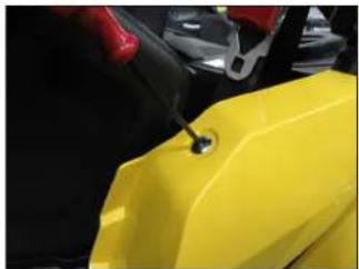
Close-up of a yellow vehicle's front compartment with metal clips and a small lock (no visible text or symbols)STEP 2
Remove the two bolts from the front of the driver's side body panel
natural_image
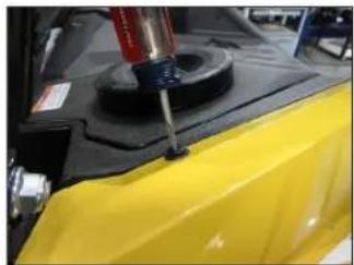
Close-up of a yellow plastic container with a small hole, being handled by red clamps (no visible text or symbols)STEP 3
Remove the screw from the top of the body panel.
natural_image
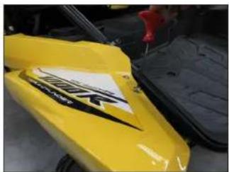
Close-up of a yellow off-road vehicle with black markings and a red tool inserted (no visible text or symbols)STEP 4
Remove the two screws from the rear of the body panel.
natural_image
Close-up of a yellow car hood with a red and black mechanical component mounted on top (no visible text or symbols)STEP 5
Remove the clip from the top of the body panel.

natural_image
Close-up of a black and yellow off-road vehicle chassis with visible tires and mounting brackets (no text or symbols)STEP 6
Remove the body panel from the vehicle.

natural_image
Close-up of a vehicle's rear suspension system with visible tire and wheel components (no text or symbols)STEP 7
Remove the bolt from the top of the lower side panel.

natural_image
Close-up of a hand using a screwdriver to adjust or install a car interior panel (no visible text or symbols)STEP 8
Remove the two clips from the front of the lower side panel, and remove the panel from the vehicle.
Page 4 • J. Audio, Inc., 2017 Continued on Next Page
SB-Y-YXZ1/10TW3 INSTR_SKU#011479

natural_image
Close-up of a hand adjusting a mechanical vehicle component, no visible text or symbolsSTEP 9
Remove the seat belt bolt.
natural_image
Close-up of a mechanical component with no visible text or symbolsSTEP 10
Lift up on the driver's seat, and remove the seat from the vehicle.

natural_image
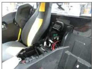
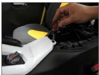
Close-up of a hand using a tool to adjust or install electronic components on a vehicle chassis (no visible text or symbols)STE P 11
Remove the four upper seat bracket bolts.
natural_image
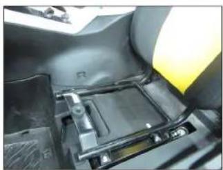
Interior view of a vehicle's dashboard and seat assembly (no visible text or symbols)STEP 12
Remove the upper seat bracket from the vehicle.
natural_image
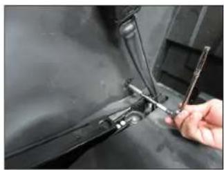
Close-up of a hand inserting a red screwdriver into a car's engine compartment (no visible text or symbols)STEP 13
Remove the four clips from the top of the upper seat bracket trim panel.
natural_image
Close-up of a hand using a wrench to adjust or install a mechanical component (no visible text or symbols)STEP 14
Remove the two clips from the driver's side of the lower console panel.

natural_image
Interior view of a car showing a white plastic vehicle component with yellow and black stripes, no visible text or symbols.STEP 15
Lift up on the back of the upper console panel to unclip it.
natural_image
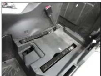
Interior view of a vehicle cabin showing seats, battery pack, and wiring (no visible text or symbols)STEP 16
Remove the upper console panel from the vehicle.
Page 5 • J. Audio, Inc., 2017 Continued on Next Page
natural_image
Close-up of a hand inserting a red component into a car's engine compartment (no visible text or symbols)STEP 17
Remove the clip from the dash trim panel over the center console.

natural_image
Close-up of a hand adjusting a white car's door panel with a red tool, no visible text or symbolsSTEP 18
Remove the two screws from the bonnet trim panel, and remove the panel from the vehicle.
natural_image
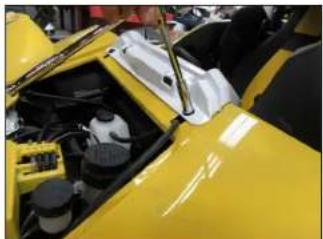
Close-up of a yellow sports car hood with visible engine compartment and dashboard (no text or symbols)STEP 19
Remove the two bolts from the top of the dash trim panel.
natural_image
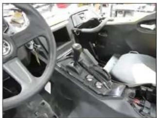
Interior view of a car showing steering wheel, gear shift, and dashboard (no visible text or symbols)STEP 20
Remove the dash trim panel from the vehicle.
Page 6 • JL Audio, Inc., 2017 Continued on Next Page
SB-Y-YXZ1/10TW3 INSTR_SKU#011479

natural_image
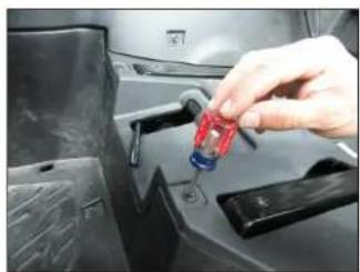
Close-up of a hand inserting a plug into a car's battery compartment (no visible text or symbols)STEP 21
Remove the four clips from the top of the lower console panel.
natural_image
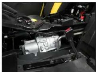
Close-up of a mechanical assembly with visible wiring and components (no text or symbols)STEP 22
Remove the lower console panel from the vehicle.

natural_image
Hand holding a red tool inside a black car dashboard (no visible text or symbols)STEP 23
Remove the clips from the front of the upper and lower rear panels.
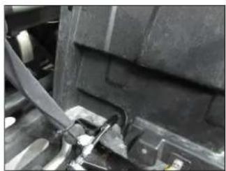
natural_image
Close-up of a car's front wheel and dashboard components (no visible text or symbols)STEP 24
Remove the bolt from the front of the lower rear panel.

natural_image
Close-up of a hand using a tool to adjust or install a component on a vehicle (no visible text or symbols)STEP 25
Remove the bolts from the front of the footwell.
natural_image
Close-up of a mechanical component with visible joints and a tool, no text or symbols presentSTEP 26
Remove the bolt from the back of the lower rear panel.

natural_image
Close-up of industrial machinery components with visible wiring and dust (no text or symbols)STEP 27
Remove the bolt from the back of the upper rear panel.

natural_image
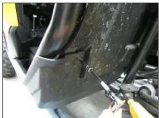
Close-up of a car's front panel with a screwdriver inserted, showing mechanical components (no visible text or symbols)STEP 28
Remove the two bolts from the side of the skid panel.
Page 6 • JL Audio, Inc., 2017 Continued on Next Page
SB-Y-YXZ1/10TW3 INSTR_SKU#011479
natural_image
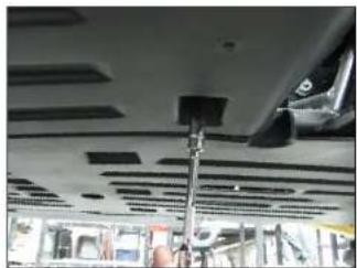
Interior view of a vehicle ceiling with visible structural elements and a hand holding a smartphone (no text or symbols)STEP 29
From below the vehicle, remove the two bolts from under the skid panel.

natural_image
Close-up of a hand adjusting a mechanical component with no visible text or symbolsSTEP 30
Remove the four lower seat bracket bolts.

natural_image
Close-up of a metallic plastic panel with internal ribs and mounting holes (no text or symbols visible)STEP 31
Remove the lower seat bracket from the vehicle.

natural_image
Close-up of a vehicle chassis frame with visible wiring and components (no text or symbols)STEP 32
Remove the lower rear panel from the vehicle.
natural_image
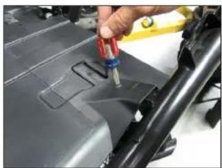
Close-up of a hand using a tool to inspect or repair a car body panel (no visible text or symbols)STEP 33
Remove the four clips from the top of the lower seat bracket trim panel, and remove the panel from the vehicle.
natural_image
Close-up of a car's front bumper and side panel (no visible text or symbols)STEP 34
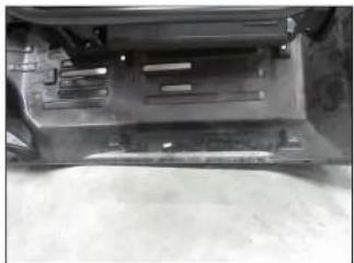
Lower the skid panel down, as shown. It is not necessary to completely remove the panel from the vehicle.
natural_image
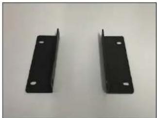
Two black metal bracket plates with mounting holes, displayed against a plain background (no text or symbols visible)STEP 35
Pictured are the Brackets. The sides with the longer flange get attached to the vehicle's frame rails in the following steps.
natural_image
Close-up of a hand using a tool to adjust or install a mechanical component (no visible text or symbols)STEP 36
Secure a Bracket to the factory holes in the rear frame rail using a pair of 1/4 - 20 x 1" Serrated Flange Head Bolts above the frame and a pair 1/4" Serrated Spring Lock Washers and 1/4 - 20 Hex Nuts below the frame, as shown.
Do not fully tighten at this time.
Page 6 • J. Audio, Inc., 2017 Continued on Next Page
SB-Y-YXZ1/10TW3 INSTR_SKU#011479
natural_image
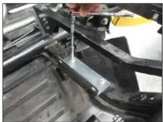
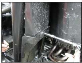
Close-up of a mechanical assembly with metallic components and a red component (no visible text or symbols)STEP 37
Secure a Bracket to the factory holes in the front frame rail using a pair of 1/4 - 20 x 1" Serrated Flange Head Bolts above the frame and a pair 1/4" Serrated Spring Lock Washers and 1/4 - 20 Hex Nuts below the frame, as shown.
Do not fully tighten at this time.
natural_image
Close-up of a black mechanical component with a central circular speaker and mounting bracket (no visible text or symbols)STEP 38
Place the enclosure face up on a flat surface. Apply Foam Tape the recessed area, as shown.
natural_image
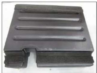
Black plastic mechanical component with three parallel grooves (no text or symbols visible)STEP 39
Turn the enclosure over, and apply Foam Tape to the recessed area, as shown.

natural_image
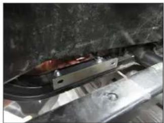
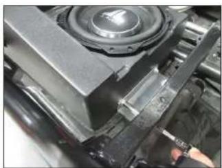
Close-up of a black speaker component mounted on a vehicle chassis, with no visible text or symbols.STEP 40
From below the frame, raise the Stealthbox* into position.
natural_image
Close-up of a mechanical component with a speaker and clamped parts, no visible text or symbolsSTEP 41
Align the threaded inserts in the side of the enclosure with the slots in the two Brackets. Secure the enclosure to each bracket using a pair of 1/4 - 20 x 1" Serrated Flange Head Bolts, and fully tighten.
Fully tighten the two 1/4 - 20 x 1" Serrated Flange Head Bolts holding the Brackets to the frame rails.
natural_image
Black plastic metal bracket with cutouts and mounting holes (no text or symbols visible)STEP 42
Place the lower seat bracket trim panel on a flat surface, as shown.

natural_image
Exterior view of a mechanical assembly with black components and brown frame (no visible text or symbols)STEP 43
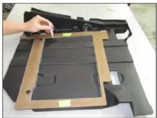
Tape the two halves of the Template together, position the template over the lower seat bracket trim panel, and secure using a pair of factory clips, as shown.
natural_image
Hand placing a component into a cardboard box on a white surface (no text or symbols visible)STEP 44
Mark the left and middle sections in the Template onto the lower seat bracket trim panel.

natural_image
Exterior view of a dark plastic mechanical component with cutouts and mounting holes (no text or symbols visible)STEP 45
Remove the clips, and remove Template.
natural_image
Disassembled black plastic components laid out on a white surface (no text or symbols visible)STEP 46
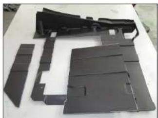
Carefully cut along the marks to remove the two sections of the lower seat bracket trim panel, as shown.
natural_image
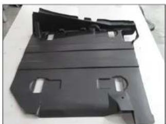
Black plastic mechanical component with cutouts and mounting holes (no text or symbols visible)STEP 47
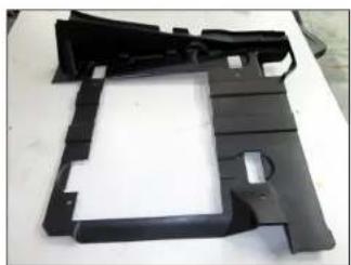
Pictured is the lower seat bracket trim panel after cutting.
natural_image
Close-up of a mechanical component with a speaker grille and mounting bracket (no visible text or symbols)STEP 48
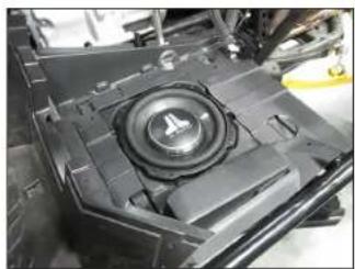
Connect speaker cable to the barrier strip on the side of the enclosure, and route the cable as necessary.
Reinstall the lower seat bracket trim panel, as shown.
Page 6 • JL Audio, Inc., 2017 Continued on Next Page
natural_image
Close-up of industrial machinery components with visible wiring and dust (no text or symbols)STEP 49
Reinstall the skid panel, lower rear panel, and the lower seat bracket.

natural_image
Interior view of a vehicle's seat frame and dashboard compartment (no visible text or symbols)STEP 50
Reinstall the upper seat bracket trim panel, lower console panel, upper console panel, dash trim panel, and bonnet trim panel.

text_image
60th Anniversary TTLR TMLDERSTEP 51
Reinstall the seat belt bolt, the lower side panel, and the body panel.

natural_image
Close-up of a yellow and black off-road vehicle with large tires, no visible text or symbolsSTEP 52
Reinstall the upper seat bracket and seat.
Page 7 • J. Audio, Inc., 2017
SB-Y-YXZ1/10TW3 INSTR_SKU#011479
CONGRATULATIONS!
You have completed the installation for this model! Enjoy your new Stealthbox ^® !

natural_image
Interior view of a yellow and black off-road vehicle with white seatbelt (no visible text or symbols)MID/HIGH FREQUENCY DRIVER FITMENT
SB-Y-YXZSPKR/MX650 speaker pods are also available for your vehicle. Each weatherproof pod is designed for a perfect fit and houses a premium JL Audio coaxial system.
SB-Y-YXZ1-SPKR/MX650
SKU#
94643
JLAUDIO. How we play:
(954) 443-1100
www.jlaudio.com
All open indicators are subject to change without notice. "L.Audic" and the L.Audic logo, and "Stellblood" and the Stellblood logo are sequenced understand of L.Audic, Inc. "Avec of the DNA", in response to logo, and "Buccin play" on reference of L.Audic line. Fated on ISX = 92718.3. (Audic) Inc. = Buccin day/week information plot, visit online at www.jund.com.
JLA-SKU# 011479 • ver. 07.25.2017 • 10369 NORTH COMMERCE PARKWAY • MIRAMAR, FLORIDA • 33025 • USA