Stealthbox SB-S-BRZFRS/10TW3 - Subwoofer JL Audio - Free user manual and instructions
Find the device manual for free Stealthbox SB-S-BRZFRS/10TW3 JL Audio in PDF.

User questions about Stealthbox SB-S-BRZFRS/10TW3 JL Audio
0 question about this device. Answer the ones you know or ask your own.
Ask a new question about this device
Download the instructions for your Subwoofer in PDF format for free! Find your manual Stealthbox SB-S-BRZFRS/10TW3 - JL Audio and take your electronic device back in hand. On this page are published all the documents necessary for the use of your device. Stealthbox SB-S-BRZFRS/10TW3 by JL Audio.
USER MANUAL Stealthbox SB-S-BRZFRS/10TW3 JL Audio
INSTALLATION GUIDE for the
SB-S-BRZFRS/10TW3
SKU# 94564
2013-Up Subaru BRZ, 2013-2016 Scion FRS, & 2017-Up Toyota 86
natural_image
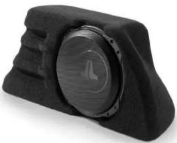
Close-up of a black mechanical component with a circular dial and textured body (no visible text or symbols)Thank you for choosing a JL Audio Stealthbox ^® for your automotive sound system.
With proper installation, your new vehicle-specific enclosed subwoofer system
will deliver years of listening pleasure.
We strongly recommend that you have your new Stealthbox® installed by your authorized JL Audio dealer. The installation professionals employed by your dealer have the necessary tools and experience to disassemble and reassemble your vehicle properly. If you prefer to perform your own installation, please read this installation guide completely before beginning the process.
JL AUDIO.
Ahead of the Curve
SB-5-BRZ/10IW3 INSTR_SKU# 011353
! IMPORTANT
If you choose to perform the installation yourself, it is absolutely vital that the Stealthbox* be properly mounted to the vehicle according to these instructions. Failure to mount the enclosure properly presents two problems:
1) The sub-bass performance will suffer due to the movement of the enclosure caused by the force exerted by the woofer(s).
2) A loose enclosure presents a serious safety hazard in the event of a collision or sudden deceleration.
INSTALLATION DIFFICULTY:

ESTIMATED TIME: 1 HOUR
SPECIFICATIONS
Enclosure Type: Sealed
Driver Type: 10TW3-D4
Nominal Impedance: 2 ohms
Continuous Power Handling: 400 watts (RMS method)
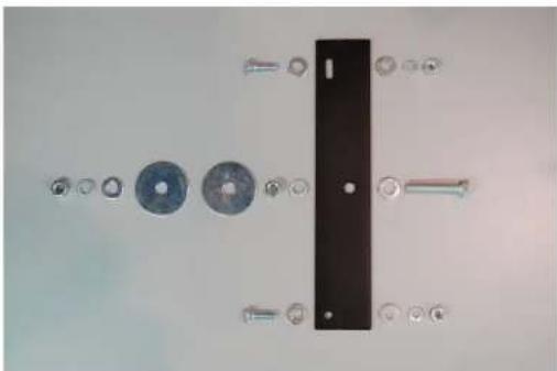
INCLUDED HARDWARE
(1) BRZ Mounting Bracket
(2) 1/4 - 20 × 1" Bolt
(4) 1/4" Flat Washer
(2) 1/4" Lock Washer
(2) 1/4 - 20 Hex Nut
(1) 3/8 - 16 x 2" Bolt
(2) 3/8" Flat Washer
(2) 3/8" Fender Washer
(2) 3/8" Lock Washer
(2) 3/8 - 16 Hex Nut
natural_image
Exploded view of a mechanical assembly with multiple components and a central black block (no text or symbols visible)Continued on Next Page
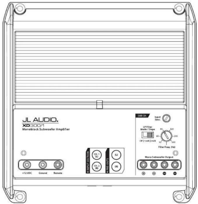
POWER RECOMMENDATION
JL Audio recommends high quality amplifiers such as the JL Audio XD300/1v2. The diagram below shows the recommended crossover settings for the XD300/1v2. For a detailed description of the amplifier settings, consult the owner's manual for the amplifier. If another amplifier is being used, please reference this illustration and use similar settings on that amplifier.
text_image
JL AUDIO. x0300/1 Monoblock Subwoofer Amplifier +12 VDC Ground Remote HINDS SECTION CH. 1 BJ CH. 2 BJ FHL OUT1 SUB CH Input Semi. LP Filter Mode / Slope RO 120 OP [12dB] 124dB 60 50 503 Filter Free (Hz) Mono Subwoofer OutputCONNECTIONS
Using quality power, signal, and speaker wire is essential in ensuring the performance of your Stealthbox®. JL Audio recommends using a 4 AWG power kit such as the XD-PCS4-1B for your Stealthbox® amplifier. Other kits are available should you be using more than one amplifier. Signal wire such as the JL Audio Premium Audio Interconnect Cables should be used to provide signal for both channels of the amplifier. JL Audio recommends using 12AWG speaker wire for subwoofers.
natural_image
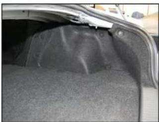
Interior view of a car trunk showing the rearrest and fuselage (no visible text or symbols)STEP 1
Empty cut the trunk of the vehicle.
natural_image
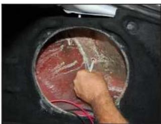
Close-up of a hand using a tool to test or inspect the interior of a circular metal object (no visible text or symbols)STEP 2
Using a Phillips head screwdriver, remove the subwoofer from the Stealthbox ^4 . Place the enclosure into position and use a Sharpie ^® to mark the location of the hole in the box onto the trunk liner. Remove the enclosure.
Note: It is not necessary to remove the grille before removing the subwoofer.
natural_image
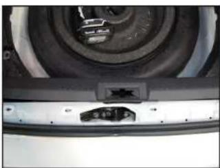
Close-up of a car wheel and rear bumper with a small connector (no visible text or symbols)STEP 3
Carefully undip and remove the trunk sill panel.

natural_image
Black plastic mechanical component with mounting holes, resting on a wooden surface (no text or symbols visible)STEP 4
Remove the five clips that hold in the passenger side trunk liner and remove the liner. Cut a 1/2" diameter hole in the liner where marked in Step 2.
natural_image
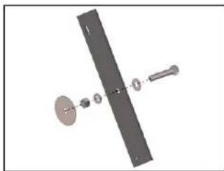
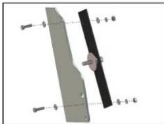
Mechanical assembly diagram showing a rotating shaft with attached components (no text or labels)STEP 5
Create the illustrated assembly using a 3/8 - 16 x 2" Bolt, a 3/8" Lock Washer, a 3/8 - 16 Hex Nu, and a 3/8" Fender Washer.
natural_image
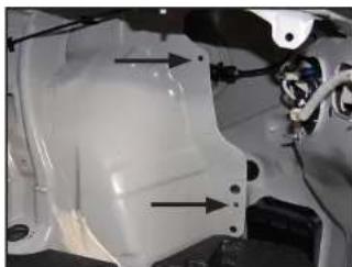
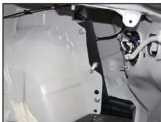
Close-up of a white mechanical component with two black arrows pointing to features, no visible text or symbols.STEP 6
Pictured is the passenger side of the trunk with the trunk liner removed. Locate the two indicated holes in the metal brace.
natural_image
Diagram of a mechanical component with labeled parts (no readable text or symbols)STEP 7
Attach the assembly from Step 5 to the holes indicated in Step 6 using a pair of 1/4 - 20 x 1" Bolts, four 1/4" Hat. Washers, two 1/4" Lock Washers, and two 1/4 - 20 Hex Bolts as illustrated.
natural_image
Close-up of a mechanical assembly with visible components and wiring (no text or symbols)STEP 8
Pictured is the assembly secured to the metal brace.
Note: The 3/8" Fender Washer isn't shown in this image.
natural_image
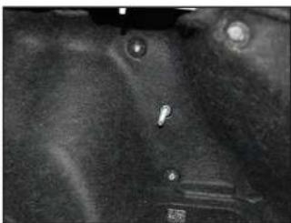
Close-up of a dark, textured surface with small circular and rectangular features (no visible text or symbols)STEP 9
Reinstall the trunk liner, allowing the 3/8 - 16 x 2" Bolt to pass through the hole cut in Step 4.

natural_image
Close-up of a car engine vent with exposed internal components and wiring (no visible text or symbols)STEP 10
Connect speaker cable to the terminal cup on the Stealthbox ^® and place the enclosure back into position, allowing the 3/8 16 x 2" Bolt to pass through the hole in the back of the enclosure.
natural_image
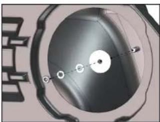
Close-up of a mechanical component with circular features and internal components (no visible text or symbols)STEP 11
Slide the other 3/8" Fender Washer, a 3/8" Flat Washer, a 3/8" Lock Washer, and a 3/8 - 16 Hex Nut over the 3/8 - 16 x 2" Bolt, and firmly tighten.

natural_image
Close-up of a car's rear bumper with a speaker grille (no visible text or symbols)STEP 12
Reinstall the suowoofer.
Page 4 • JL Audio, Inc., 2017
CONGRATULATIONS!
You have completed the installation for this model. Enjoy your new Stealthbox®!
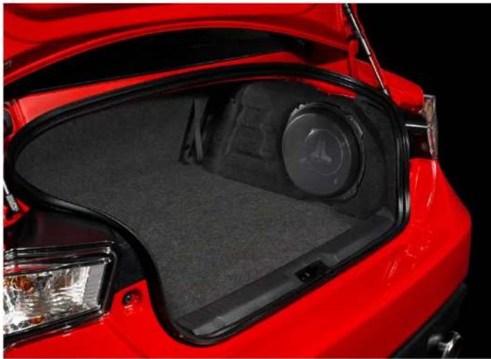
natural_image
Close-up of a red car trunk with visible rear vent and dashboard (no text or symbols)MID/HIGH FREQUENCY DRIVER FITMENT
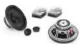
A variety of JL Audio coaxial and component systems will fit in the factory speaker locations of you vehicle.
Front Speaker Size / Location: 6-1/2"- Front Doors Fits JL Audio Models: C1-650x, C1-650, C2-650x, C2-650, C3-650, C5-650x, C5-650, & ZR570-CSi
Rear Speaker Size / Location: 3-1/2"- Rear Quarter Panels Fits JL Audio Models: C2-350x
JL AUDIO®
Ahead of the Curve
| (954) 443-1100 | www.jlaudio.com |
| All specifications are required to charge with other non-A, B, and C, R, and other B, S, and B, and the S, B, and B, and the S, B, and B, and the S, B, and B, and the S, B, and B, and the S, B, and B, and the S, B, and B, and the S, B, and B, and the S, B, and B, and the S, B, and B, and the S, B, and B, and the S, B, and B, and the S, B. | |
10369 NORTH COMMERCIAL PARKWAY · MIHAMAN, FLORIDA · 33025 · USA