Stealthbox SB-POL-GNRL/10TW3 - Caisson de basse pour voiture JL Audio - Free user manual and instructions
Find the device manual for free Stealthbox SB-POL-GNRL/10TW3 JL Audio in PDF.

User questions about Stealthbox SB-POL-GNRL/10TW3 JL Audio
0 question about this device. Answer the ones you know or ask your own.
Ask a new question about this device
Download the instructions for your Caisson de basse pour voiture in PDF format for free! Find your manual Stealthbox SB-POL-GNRL/10TW3 - JL Audio and take your electronic device back in hand. On this page are published all the documents necessary for the use of your device. Stealthbox SB-POL-GNRL/10TW3 by JL Audio.
USER MANUAL Stealthbox SB-POL-GNRL/10TW3 JL Audio
natural_image
Black plastic electronic component with slots and mounting holes (no visible text or symbols)Stealthbox®
INSTALLATION GUIDE
for the
SB-POL-GNRL/10TW3
SKU# 94656
2016 & Up Polaris General
Enclosure Type: Sealed
Driver Type: 10TW3-D4
Nominal Impedance: 2 ohms
Continuous Power Handling: 400 watts (RMS method)
SB-POL-GNRL/10TW3 INSTR_SKU# 011501
! IMPORTANT
If you choose to perform the installation yourself, it is absolutely vital that the Stealthbox ^* be properly mounted to the vehicle according to these instructions. Failure to mount the enclosure properly presents two problems:
1) The sub-bass performance will suffer due to the movement of the enclosure caused by the force exerted by the woofer(s).
2) A loose enclosure presents a serious safety hazard in the event of a collision or sudden deceleration.
INSTALLATION DIFFICULTY:

ESTIMATED TIME: 3-4 HOURS

text_image
JL AUDIO - Quality & Design - SBX STEALTHBOX®Thank you for choosing a JL Audio Stealthbox* for your automotive sound system. With proper installation, your new vehicle-specific enclosed subwoofer system will deliver years of listening pleasure.
We strongly recommend that you have your new Stealthbox ^® installed by your authorized JL Audio dealer. The installation professionals employed by your dealer have the necessary tools and experience to disassemble and reassemble your vehicle properly. If you prefer to perform your own installation, please read this installation guide completely before beginning the process.
Continued on Next Page
INCLUDED HARDWARE

text_image
BOM ID Qty SKU Description 1 3 15 1164 1/4 - 20 U-Nut 2 7 15 3818 3 7 15 3729 1/4 - 20 x 1" Stainless Steel Serrated Flange Bolt 4 1 15 3936 Top Bracket 5 2 15 3931 M6 1 x 20mm Stainless Steel Hex Head Bolt 6 4 15 3932 M6 Stainless Steel Flat Washer 7 1 15 3937 Front Bracket 8 2 15 3933 M6 Stainless Steel Serrated Flange Locknut - 1 150249 Foam Strips (not shown) ① ② ③ ④ ⑤ ⑥ ⑦ ⑧ ⑨ ⑩Note: For optimum performance, JL Audio recommends applying the included Foam Strips (or sound damping material) to surrounding plastic panels to reduce unwanted vibrations.
POWER RECOMMENDATION
JL Audio recommends high quality amplifiers such as the JL Audio MX300/1. The diagram below shows the recommended crossover settings for the MX300/1. For a detailed description of the amplifier settings, consult the owner's manual for the amplifier. If another amplifier is being used, please reference this illustration and use similar settings on that amplifier.
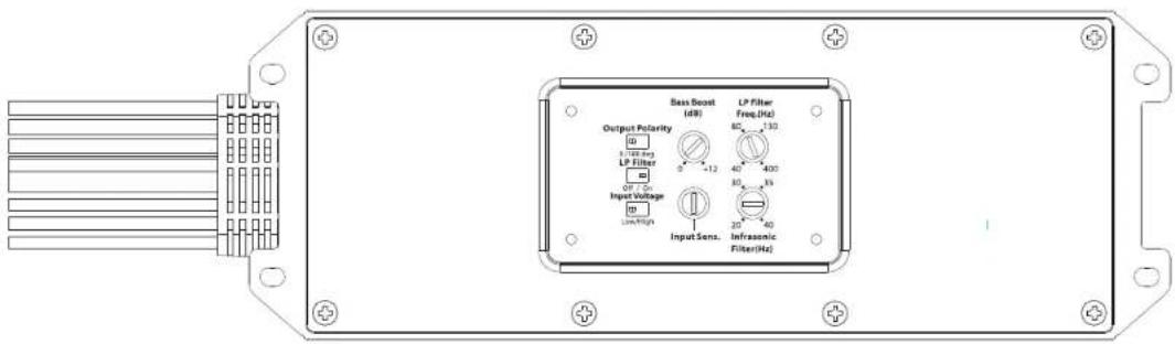
text_image
Output Polarity LP Filter Input Voltage Low/High Sass Boost (dB) LP Filter Freq.(Hz) 80 130 40 400 30 35 20 40 Infracantic Filter(Hz) Input Sens.CONNECTIONS
Using quality power, signal, and speaker wire is essential in ensuring the performance of your Stealthbox*. JL Audio recommends using a 4 AWG power kit such as the XD-PCS4-1B for your Stealthbox® amplifier. Other kits are available should you be using more than one amplifier. Signal wire such as the JL Audio Premium Audio Interconnect Cables should be used to provide signal for both channels of the amplifier. JL Audio recommends using 12AWG speaker wire for subwoofers such as our XC-BCS12-25.

natural_image
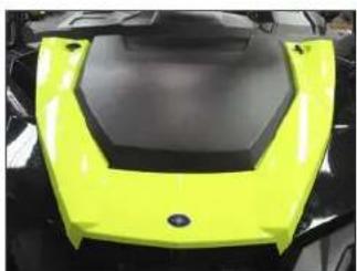
Top-down view of a bright yellow and black sports car hood (no text or symbols visible)STEP 1
Empty the vehicle.
Unclip and remove the bonnet.

natural_image
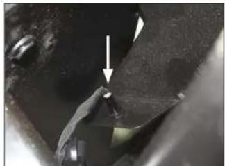
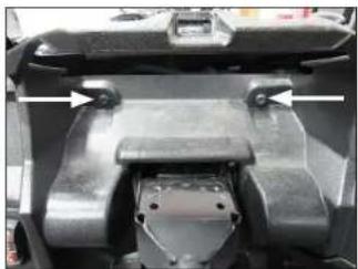
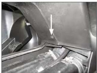
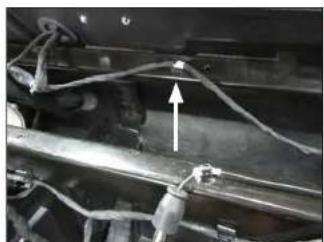
Close-up of a mechanical component with visible parts and an arrow indicating a specific feature (no text or symbols present)STEP 2
Remove the two indicated clips from the top of the fender.
Repeat for the opposite side.

natural_image
Close-up of a car's internal components with arrows indicating movement or force, no visible text or symbolsSTEP 3
Remove the two indicated clips from the top of the fender, and one from the corner of the upper dash panel.
Repeat for the opposite side.
natural_image
Close-up of a mechanical component with arrows pointing to features, no visible text or symbolsSTEP 4
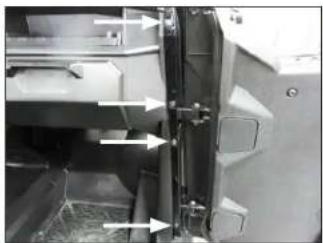
Remove the two indicated clips and two indicated bolts from the door jamb.
Repeat for the opposite side.
Page 4 • JL Audio, Inc., 2017 Continued on Next Page
SB-POL-GNRL/10TW3 INSTR_SKU# 011501

natural_image
Interior view of a vehicle showing structural components and airflow arrows (no visible text or symbols)STEP 5
Remove the remaining three indicated clips from the top of the upper dash panel.
natural_image
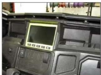
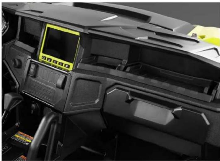
Interior view of a vehicle dashboard with control panels and a digital display (no visible text or symbols)STEP 6
Unclip the front of the upper dash panel.
natural_image
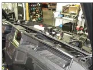
Interior view of a car dashboard with visible mechanical components and equipment (no text or symbols)STEP 7
Remove the upper dash panel from the vehicle.
natural_image
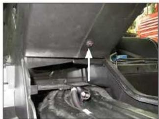
Close-up of a mechanical component with a white arrow pointing to a small feature (no text or symbols visible)STEP 8
Reach down through the dash opening on the passenger side, and unclip the LED.

natural_image
Close-up of a mechanical component with a white arrow pointing to a specific part (no visible text or symbols)STEP 9
Reach down through the dash opening on the driver's side, and unclip the LED.
natural_image
Close-up of a hand holding a circular mechanical part with an arrow pointing upward (no visible text or symbols)STEP 10
Reach down through the dash opening in the center, and unclip the LED.

natural_image
Close-up of a mechanical assembly with visible wiring and components (no text or symbols)STE P 11
Unplug the two harnesses from the back of the source unit. Unplug the antenna connector.

natural_image
Close-up of a mechanical component with wiring and a small electronic component (no visible text or symbols)STEP 12
Unplug the harness from the back of the ignition switch.
Page 5 • J. Audio, Inc., 2017 Continued on Next Page
SB-POL-GNRL/10TW3 INSTR_SKU# 011501

natural_image
Close-up of hands holding electrical components with arrows indicating direction (no visible text or symbols)STEP 13
Unplug the harnesses from the light switch and 4x4 switch.

natural_image
Close-up of a mechanical control panel with no visible text or symbols on the face or backgroundSTEP 14
Carefully unclip the dash bezel below the source unit.

natural_image
Interior view of a vehicle showing mechanical components and wiring (no visible text or symbols)STEP 15
Unplug the harness from the winch switch, and disconnect the wiring from the power outlet.

natural_image
Interior view of a car showing a vehicle's rear panel with two connectors and a switch, no visible text or symbols.STEP 16
Remove the dash bezel from the vehicle.
Remove the two indicated bolts from the lower dash panel.
natural_image
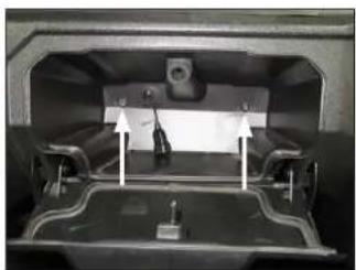
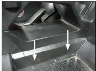
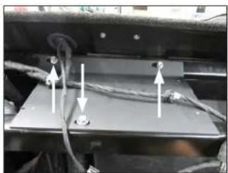
Interior view of a vehicle showing a vehicle chassis with a mounted panel and two directional arrows indicating movement or force (no text or symbols visible)STEP 17
Open the glove compartment, and remove the two indicated bolts.
natural_image
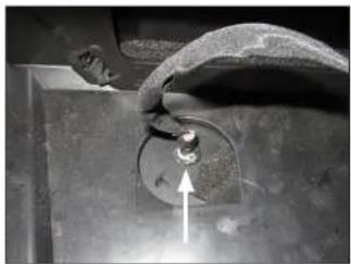
Interior view of a vehicle showing a mounted device with a highlighted component (no visible text or symbols)STEP 18
Push the grommet and USB cable through the hole in the back of the glove compartment.

natural_image
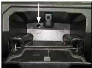
Close-up of a mechanical component with visible wiring and a small label, no readable text or symbols present.STEP 19
Unplug the harness from the back of the instrument cluster.
Remove the two indicated bolts from the instrument cluster bracket.
natural_image
Close-up of a mechanical component with metallic parts and mounting holes (no visible text or symbols)STEP 20
Remove the instrument cluster from the vehicle.
Remove the two indicated bolts from behind the instrument cluster.
Page 6 • J. Audio, Inc., 2017 Continued on Next Page
SB-POL-GNRL/10TW3 INSTR_SKU# 011501
natural_image
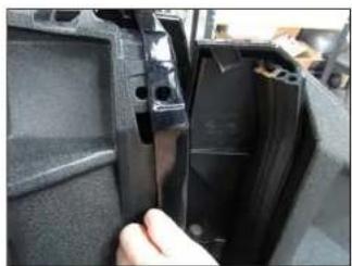
Close-up of a hand inserting a plastic component into a black plastic housing (no visible text or symbols)STEP 21
Carefully pull the both fenders outward to clear the dash.

natural_image
Interior view of a vehicle chassis with visible wiring, motors, and components (no text or symbols)STEP 22
Remove the dash from the vehicle.
natural_image
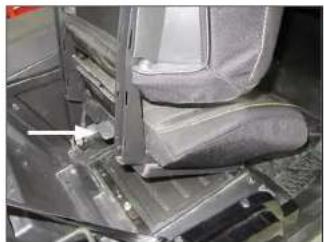
Close-up of a car interior showing seat, dashboard, and mechanical components (no visible text or symbols)STEP 23
Lift the lever on the back of the passenger seat bottom, and remove the seat from the vehicle.
natural_image
Close-up of a car's front panel showing internal components and arrows indicating movement (no text or symbols visible)STEP 24
Remove the two indicated clips from the access panel on the passenger side of the center console.

natural_image
Close-up of a car's side panel with visible wiring and mounting points (no text or symbols)STEP 25
Remove the access panel from the passenger side of the center console.
Remove the three indicated screws from the passenger side of the center console.

natural_image
Close-up of a mechanical assembly with hoses and components, no visible text or symbolsSTEP 26
Remove the four bolts from the handle on the passenger side of the center console, and remove the handle from the vehicle.

natural_image
Close-up of a mechanical component with arrows indicating movement or assembly (no visible text or symbols)STEP 27
Remove the three indicated clips from the back of the passenger side of the center console.
natural_image
Close-up of a car's front wheel and side panel, showing structural components and a white arrow pointing to a specific part (no text or symbols visible)STEP 28
Remove the indicated clip from the front of the center console pass-through.
Page 7 • J. Audio, Inc., 2017 Continued on Next Page
SB-POL-GNRL/10TW3 INSTR_SKU# 011501
natural_image
Close-up of a car's front bumper with an arrow pointing to the side panel (no visible text or symbols)STEP 29
Remove the indicated clip from the rear of the center console pass-through.
natural_image
Close-up of a mechanical component with white arrows indicating direction (no visible text or symbols)STEP 30
Remove the two indicated clips from the front of the center console near the firewall.
natural_image
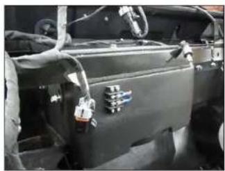
Interior view of a vehicle chassis frame with visible wiring and components (no text or symbols)STEP 31
Remove the passenger side of the center console from the vehicle.
natural_image
Close-up of a mechanical assembly with wires and connectors (no visible text or symbols)STEP 32
Remove the indicated wire clip from the upper frame near the firewall.
natural_image
Close-up of a mechanical or electrical component with wires and connectors, no visible text or symbolsSTEP 33
Position the Top Bracket over the upper dash frame, as shown, aligning the slots in the Top Bracket with the holes in the dash frame.
Slide a 1/4" Flat Washer over each of three 1/4 - 20 x 1" Serrated Flange Head Bolts. Pass an assembly through each of the slots in the Top Bracket and holes in the dash frame. Thread a 1/4 - 20 U-Nut onto each of the 1/4 - 20 x 1" Serrated Flange Head Bolts, and hand tighten.

natural_image
Close-up of a mechanical assembly with metal components and wires (no visible text or symbols)STEP 34
Position the Front Bracket behind the frame, as shown, aligning the outer holes in the Front Bracket with slots in the frame.
Slide an M6 Flat Washer over each of two M6 - 1 x 20mm Hex Head Bolts. Pass an assembly through the hole in the Front Bracket and slots in the frame. Slide an M6 Flat Washer and M6 Serrated Flange Locknut over each M6 - 1 x 20mm Hex Head Bolt, and hand tighten.
natural_image
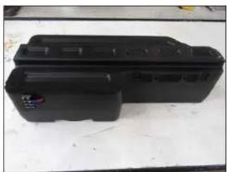
Black plastic electronic device casing on a white surface (no visible text or symbols)STEP 35
Attach Foam Tape to the enclosure, as shown.
natural_image
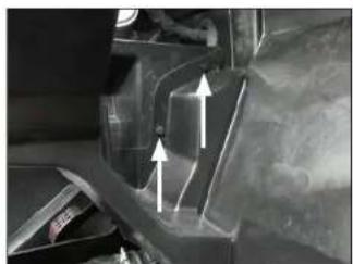
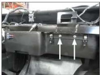
Close-up of a mechanical component with two white arrows pointing to features, no visible text or symbols.STEP 36
Lift the Stealthbox* into position, aligning the slots in the Front Bracket with the threaded inserts in the enclosure.
Slide a 1/4" Flat Washer over each of two 1/4 - 20 x 1" Serrated Flange Head Bolts. Pass an assembly through each of the slots in the Front Bracket, into the threaded inserts, and hand tighten.
Page 8 • J. Audio, Inc., 2017 Continued on Next Page
SB-POL-GNRL/10TW3 INSTR_SKU# 011501

natural_image
Close-up of a mechanical component with two white arrows pointing to features, no visible text or symbolsSTEP 37
Slide a 1/4" Flat Washer over each of two 1/4 - 20 x 1" Serrated Flange Head Bolts. Pass an assembly through each of the slots in the Top Bracket, into the threaded inserts, and fully tighten.
natural_image
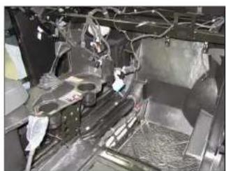
Close-up of a vehicle's internal components, possibly a battery or engine compartment, with no visible text or symbols.STEP 38
Fully tighten the two 1/4 - 20 x 1" Serrated Flange Head Bolts installed in Step 36, then fully tighten the three 1/4 - 20 x 1" Serrated Flange Head Bolts installed in Step 33 and the two M6 - 1 x 20mm Hex Head Bolts installed in Step 34.
Connect speaker cable to the barrier strip on the front of the enclosure, and route the cable as necessary.
natural_image
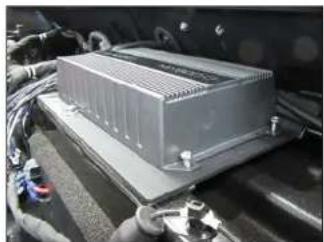
Exterior view of a modern industrial electronic device mounted on a vehicle chassis (no visible text or symbols)STEP 39
If a JL Audio MX-series amplifier is being installed, it can be mounted to the threaded holes in the Top Bracket using #8 - 32 x 1/4" machine screws (not included).

natural_image
Close-up of a motorcycle's front wheel and side brackets, no visible text or symbolsSTEP 40
Reinstall the passenger side of the center console, access panel, and handle.
natural_image
Close-up of a car engine bay with visible components and wiring (no text or symbols)STEP 41
Reinstall the dash, instrument cluster, USB cable, and grommet.

natural_image
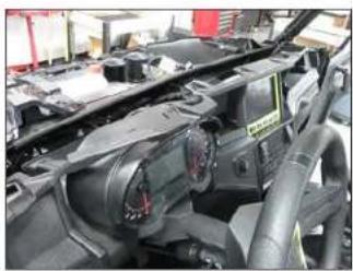
Interior view of a vehicle dashboard with a mounted electronic device (no visible text or symbols)STEP 42
Reinstall the dash bezel, LEDs, and upper dash panel.
natural_image
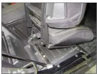
Close-up of a mechanical assembly with a gray seat and metal frame (no visible text or symbols)STEP 43
Reinstall the passenger seat.
natural_image
Close-up of a bright yellow and black plastic object with hexagonal base (no text or symbols visible)STEP 44
Reinstall the fenders and bonnet.
Note: For optimum performance, we recommend applying the included Foam Strips (or sound damping material) to surrounding plastic panels to reduce unwanted vibrations.
Page 9 • J. Audio, Inc., 2017
SB-POL-GNRL/10TW3 INSTR_SKU# 011501
CONGRATULATIONS!
You have completed the installation for this model! Enjoy your new Stealthbox ^® !
natural_image
Close-up of a black industrial machine head with control panel and yellow display (no visible text or symbols)MID/HIGH FREQUENCY DRIVER FITMENT
SB-POL-GNRLSPKR/MX650 speaker pods are also available for your vehicle. Each weatherproof pod is designed for a perfect fit and houses a premium JL Audio coaxial system.
SB-POL-GNRLSPKR/MX650
SKU#

JLAUDIO. How we play.*
(954) 443-1100
www.jleudio.com
All social behaviors are subject to change without notice. "I have" and "I have" are registered trademarks of L. hauke, Inc. "Three of the Curne" and to resupposing logo and trademarks of L. hauke Inc.
Production USA - 6/2017, 45:30, Inc. - for new detailed information please call at www.glandscn.com.
JLA-SKU# 011501 - ver. 12.05.2017 - TC369 NORTH COMMERCIF PARKWAY, MIRAMAR, HOKIDA - 33025 - USA
1
"011502"