RZ4-2KRC - Unspecified SSV Works - Free user manual and instructions
Find the device manual for free RZ4-2KRC SSV Works in PDF.

User questions about RZ4-2KRC SSV Works
0 question about this device. Answer the ones you know or ask your own.
Ask a new question about this device
Download the instructions for your Unspecified in PDF format for free! Find your manual RZ4-2KRC - SSV Works and take your electronic device back in hand. On this page are published all the documents necessary for the use of your device. RZ4-2KRC by SSV Works.
USER MANUAL RZ4-2KRC SSV Works
WARRANTY INFORMATION:
All SSV Works enclosures are covered by a limited lifetime warranty against defects in material or workmanship. All SSV Works Electronics are covered by a limited 1 year warranty against defects in material or workmanship. All Kicker Speakers are covered by a limited 1 year warranty against defects in material or workmanship. All Kicker Amplifiers are covered by a limited 2 year warranty against defects in material or workmanship. Labor for replacement of defective components is not covered. Contact SSV Works for further warranty information.

Please read and understand these instructions completely before installation to avoid possible injury, or damage to the accessory or vehicle.
TOOLS NEEDED FOR INSTALLATION
- T30 & T40 Torx Socket
- 10mm and 5.5mm Socket & Rachet or Wrench
- 4mm & 5mm Allen Wrench
- #2 & #3 Phillips Screwdriver
- Drill with 13/64", 1/8", 1/4" & 1/2" Drill bits
- Panel removal tool
- Wire Crimpers
- Wire Strippers
- Scribe or Marker
- Utility Knife
PARTS LIST IMAGES

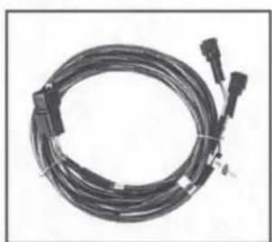
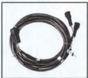
natural_image
Coiled black cable with connectors and a connector tip, no visible text or symbols- Amp Power Wire
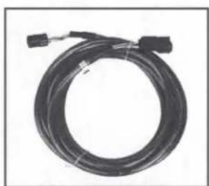
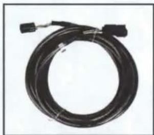
natural_image
Coiled black cable with connectors and connectors, no visible text or symbols- Front B-H1149 Speaker Wire
natural_image
Coiled black cable with connectors, no visible text or symbols- Rear B-H1151 Speaker Expansion

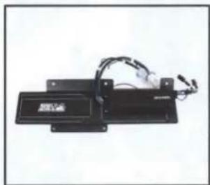
natural_image
Electronic device with attached wires and a label (no readable text or symbols)- Amp Tray with pre-loaded Kicker Amplifier

natural_image
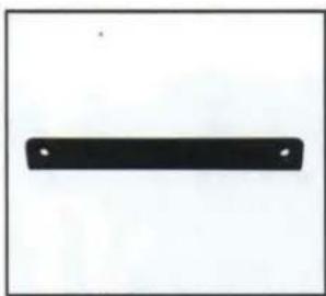
Simple black rectangular shape with two small white dots on a white background (no text or symbols)- Amp Tray Base Bracket

natural_image
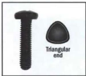
Two black mechanical components: a bolt and a washer, shown against a white background (no text or symbols)- M6 x 1.0 Screws and Washers x 2
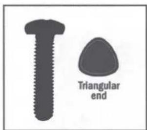
text_image
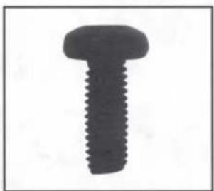
Triangular end- Self-Tapping Screw x 1

natural_image
Simple line drawing of a loop or rope with a central dot (no text or symbols)- Zip Ties x 5

natural_image
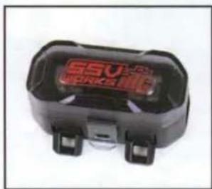
Close-up of a black electronic device labeled 'SSV WORKS' with no visible text or symbols on its body.- Fuse Holder with 40A Fuse
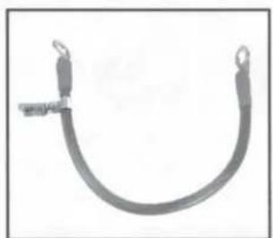
natural_image
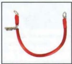
U-shaped metal wire or cable with two loop ends (no text or symbols visible)- Battery Terminal Cable
PANELS AND DASH DISASSEMBLY
natural_image
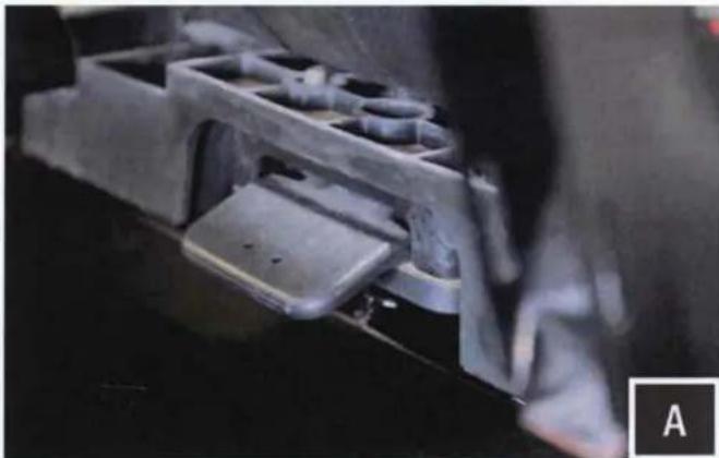
Close-up of a mechanical component with internal cavities and mounting brackets (no visible text or symbols)A. Remove driver seat by releasing the handle behind each seat, push forward slightly while lifting up

natural_image
Close-up of a hand holding a black NOS battery with attached cable, no visible text or symbols on the components.B. Disconnect the negative battery cable from the battery.

natural_image
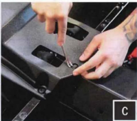
Close-up of hands using a tool to adjust or install a mechanical component, no visible text or symbolsC. Remove all of the center console push pins and T-30 Torx screws. For 4-seat models, disconnect the harness attached to the 12v accessory socket.
natural_image
Close-up of hands using a tool to adjust or install a black mechanical component (no visible text or symbols)
natural_image
Close-up of hands using a power tool to clean or repair a car engine compartment (no visible text or symbols)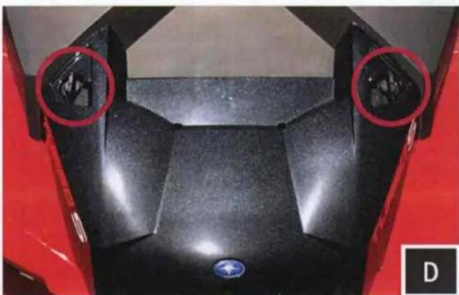
natural_image
Top-down view of a black motorcycle body with two red circular highlights highlighting the front and side (no text or symbols)D. Remove hood by turning locking pins and lifting up.
natural_image
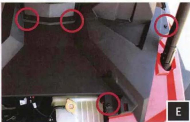
Close-up of a mechanical component with red circles highlighting features, no visible text or symbolsE. Unscrew the (4) T40 torx screws (showing driver side only in image) and extract the (2) push pins from the dash. From inside the machine, pull dash towards you to unclip. Once unclipped remove the dash.
RUNNING WIRING AND CABLES

natural_image
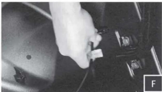
Close-up of hands cleaning a car engine compartment with a yellow tag (no visible text or symbols)F. Unwrap the tape and pull the rubber wire grommet out of the firewall.
natural_image
Close-up of a hand using a tool to connect two black corrugated wires into a vehicle chassis (no visible text or symbols)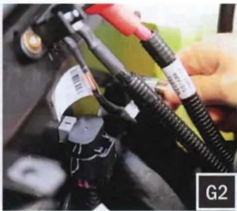
natural_image
Close-up of hands connecting automotive electrical cables to a battery pack (no visible text or symbols)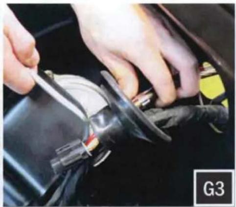
natural_image
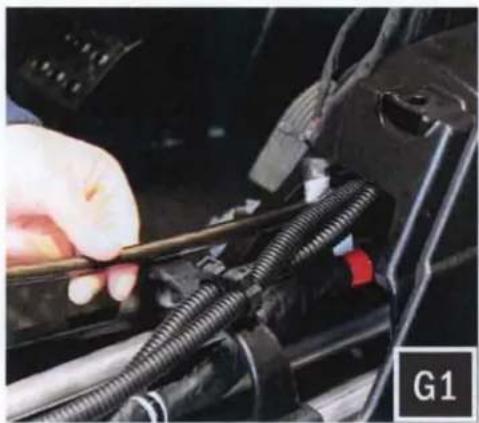
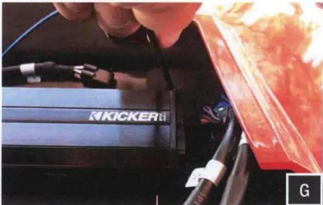
Close-up of hands using a tool to adjust or install a car body panel (no visible text or symbols)D. Feed the connector end of the Amp power wire through the center console to the other side of the firewall (G1). Then feed the power wire through the grommet hole (G2) and through the rubber grommet with the rest of the vehicle's wiring and cables (G3). Do the same for the B-H1151 rear speaker harness. The purpose of this harness is to add rear speakers - sold separately.
natural_image
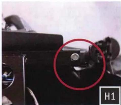
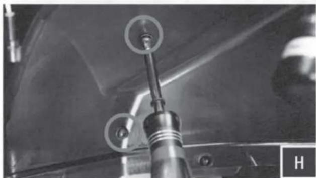
Close-up of a black optical instrument with a red circle highlighting a mechanical component, labeled H1 (no readable text or symbols)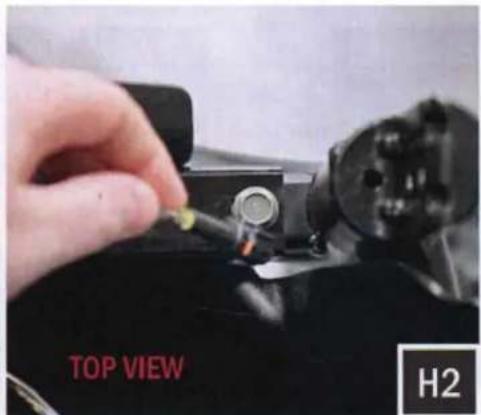
text_image
TOP VIEW H2
text_image
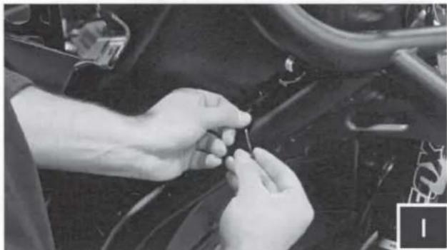
UNDERNEATH VIEW H3H. Route the front speaker wire through the opening where the firewall and roll cage bar meet on both the driver and passenger side. Leave these wires loose until the front speaker pods are to be installed.
AMP TRAY INSTALLATION
natural_image
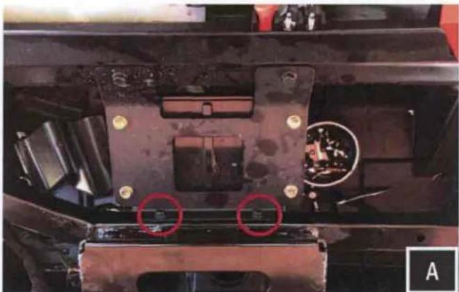
Close-up of a mechanical component with red circles highlighting two areas of interest (no visible text or symbols)A. Remove the (2) 10mm bolts circled in pink

natural_image
Close-up of a mechanical component with red arrows pointing to features, no visible text or symbolsB. Place the amp tray base bracket at the location of the (2) removed factory 10mm bolts. Re-fasten the bolts through both the amp tray base bracket and factory plate to secure to the chassis.
natural_image
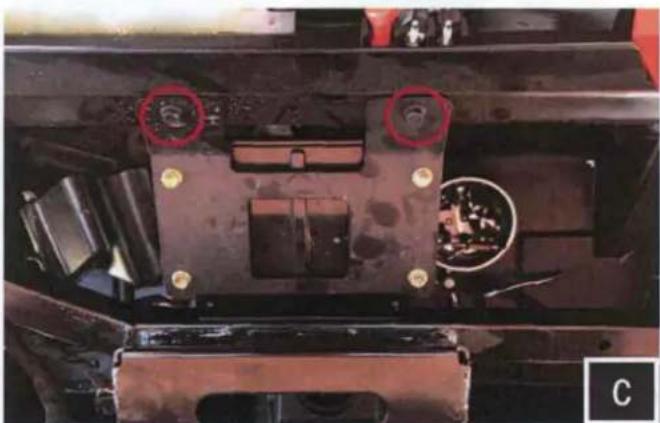
Close-up of a mechanical component with red circles highlighting features, no visible text or symbolsC. Remove the (2) 10mm bolts circled in pink

natural_image
Close-up of a red car front bumper with two black KICKERS plastic enclosures and wiring (no visible text or symbols)D. Place the amp tray into the mounting location by lining up the amp plate screw holes to the factory holes on the chassis.
natural_image
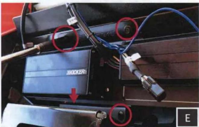
Close-up of a mechanical device with blue cables and connectors, featuring red circles highlighting specific components (no readable text or symbols)E. Secure the amp tray by using the two (2) factory bolts at the top, and two (2) M6 bolts at the bottom mounting locations.

text_image
KICKER FF. Using a scribe or punch, mark the location of the needed pilot hole on the passenger side of the tray.
AMP TRAY INSTALLATION
natural_image
Close-up of a hand inserting a KICKER brand into a red vehicle (no visible text or symbols)G. With the correct location marked, uninstall the amp tray and use a 13/64" drill bit to drill your pilot hole. With your pilot hole drilled, reinstall the amp tray. Use the self-tapping screw in the drilled hole location.
natural_image
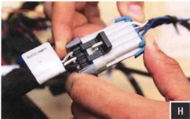
Close-up of hands assembling a black and white electronic component with wires (no visible text or symbols)H. Connect the amplifier "Front Input" to the Ride Command "Audio Amp 1" factory harness. Connect the amplifier "Rear Input" for rear speakers to "Audio Amp 2" factory harness.
WARRANTY INFORMATION:
All SSV Works enclosures are covered by a limited lifetime warranty against defects in material or workmanship. All SSV Works Electronics are covered by a limited 1 year warranty against defects in material or workmanship. All Kicker Speakers are covered by a limited 1 year warranty against defects in material or workmanship. All Kicker Amplifiers are covered by a limited 2 year warranty against defects in material or workmanship. Labor for replacement of defective components is not covered. Contact SSV Works for further warranty information.

Please read and understand these instructions completely before installation to avoid possible injury, or damage to the accessory or vehicle.
TOOLS NEEDED FOR INSTALLATION
- Wire Crimpers
- #2 Phillips Screwdriver
- Wire Strippers
- Scribe or Marker
- T-30 Torx Driver
- Utility Knife
- Drill with 1/8", 1/4" and 1/2" Drill bit
PARTS LIST IMAGES
natural_image
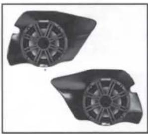
Two black plastic fan components with visible blades and mounting holes (no text or symbols)- RZ3-F65K Enclosures (1 pair)
natural_image
Close-up of a black screw with threaded shaft (no text or symbols visible)- M6 x 16mm Screws x 6

natural_image
Simple black ring shape on white background (no text or symbols)- M6 Washers x 6

text_image
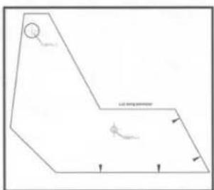
Set design parameters 30mm x 100mm- Driver Side Inside Template
text_image
φ φ φ α-α-α-α-α-α-α-α-α-α-α-α-α-α-α-α-α-α-α-α-α-α-α-α-α-α-α-α-α-α-α-α-α-α-α-α-α-α-α-α-α-α-α-α-α-α-α-α-α- Driver Side Outside Template
text_image
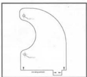
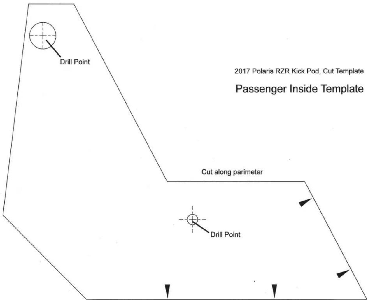
Ld string perimeter- Passenger Side Inside Template
natural_image
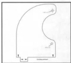
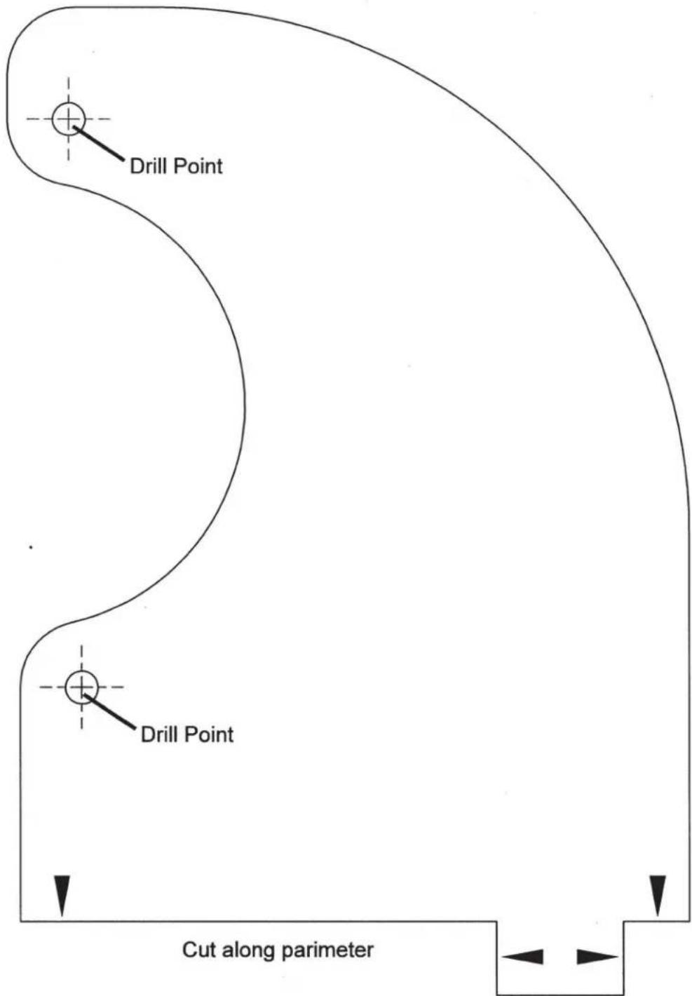
Pure diagram of a curved shape with directional arrows and no text or symbols- Passenger Side Outside Template
natural_image
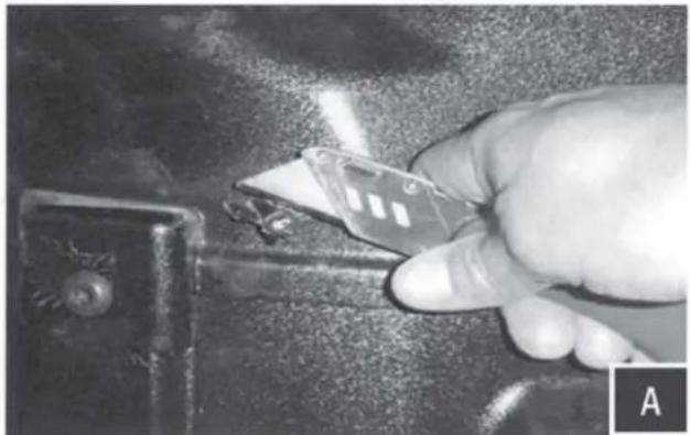
Close-up of a hand using a tool to cut a metal component, no visible text or symbolsA. Using the utility knife or another cutting tool cut off the two plastic factory nubs in the foot well, cut these as smooth as you can to the panel.
NOTE: If pod does not come pre-installed with speaker, do not use provided paper templates. Use the pod mounting holes as your drill template. Hold the pod in position and mark the drill holes through the empty pod using a scribe tool. All pilot holes will be drilled from the inside footwell.

natural_image
Close-up of hands installing or adjusting a white panel on a mechanical component (no visible text or symbols)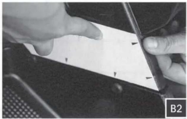
natural_image
Close-up of hands holding a white rectangular object with black arrows pointing to it, next to a dark surface (no text or symbols visible)
natural_image
Close-up of hands using a sewing machine to trim a white card (no visible text or symbols)
natural_image
Close-up of hands holding a white sheet with a pen, partially visible in a car (no text or symbols)B. Cut out the INSIDE template (Driver/Passenger) along the cut line. Position the template on the inside footwell making sure to square up the template along the factory panel as shown in image B1 and B2. Using a scribing tool, mark the center of the 2 drill points illustrated on the template as shown in B3 and B4.
natural_image
Close-up of a mechanical component with visible parts and a label 'C1' in the corner (no readable text or symbols)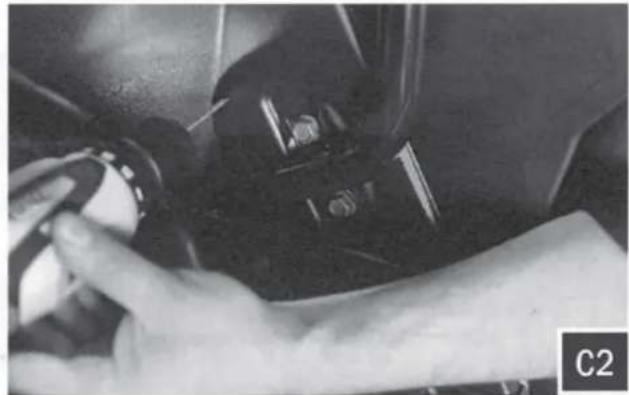
natural_image
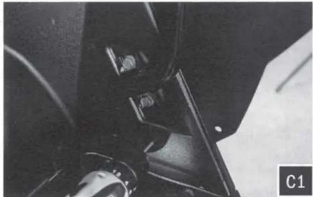
Close-up of a hand holding a small object, possibly a tool or device, in a car interior (no visible text or symbols)C. Drill a pilot hole at the places just marked with a 1/8" drill bit. Then follow up by using a 1/4" drill bit in the lower pilot hole (for mounting the pod) and a 1/2" drill bit in the upper pilot hole (for speaker cable).

natural_image
Close-up of a hand using a tool to clean or store items on a dark vehicle door (no visible text or symbols)
natural_image
Close-up of hands holding a white curved object with a small square base, against a dark background (no text or symbols visible)
natural_image
Close-up of hands holding a piece of paper with a circular hole, no visible text or symbols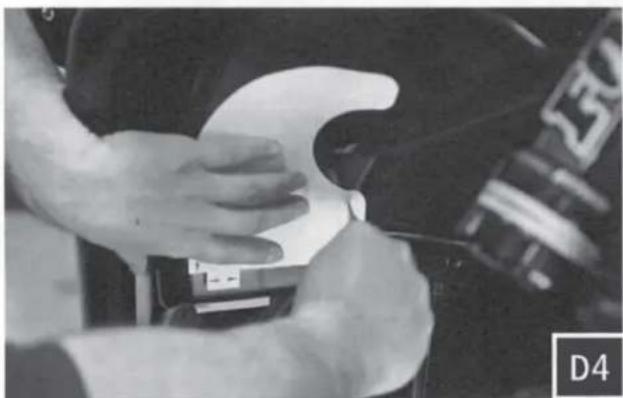
natural_image
Close-up of hands adjusting a white object on a dark surface, no visible text or symbols
natural_image
Close-up of hands cleaning a car tire with a white plastic clip (no visible text or symbols)D. Cut out the OUTSIDE template (Driver/Passenger) along the cut line. Position the template on the outside footwell. Make sure the bottom of the template lines up along the bottom edge and tab of the factory panel as shown in figure D1-D3. Using a scribing tool, mark the center of the 2 drill points illustrated on the template as shown in D4 and D5. When marking these holes, make sure the template is flush against the factory panel.

natural_image
Close-up of a mechanical component with a pointed tip and circular base, possibly a valve or pump assembly (no visible text or symbols)
natural_image
Close-up of a metallic mechanical component with visible joints and a labeled section E2 (no readable text or symbols)E. Drill a pilot hole at the places just marked with a 1/8" drill bit. Then follow up by using a 1/4" drill bit for both pilot holes (for mounting the pod).
natural_image
Close-up of a hand holding a small electronic component, possibly a switch or connector (no visible text or symbols)F. Route the speaker cable attached to the pod through the inside footwell 1/2" hole made in Step D.

natural_image
Close-up of a hand adjusting a Kicker brand wheel component (no visible text or symbols)G. Position the speaker pod in place and line up with drilled mounting holes
natural_image
Close-up of a mechanical assembly with a metallic rod and circular components, no visible text or symbols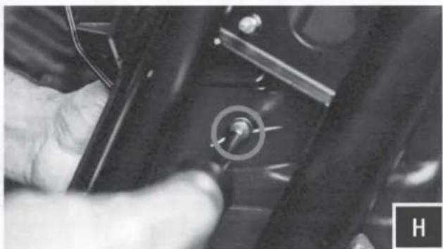
natural_image
Close-up of a hand holding a small mechanical component with a circular knob (no visible text or symbols)H. With the provided M6 screws and washers, loosely mount the pod through the 3 holes previously drilled. Once all screws have been inserted into the pod, hand tighten all 3 screws.
natural_image
Close-up of hands adjusting a small component on a vehicle wheel (no visible text or symbols)I. Connect the B-H1149 cable to the speaker pods and zip tie all cables to the frame

natural_image
Close-up of hands installing or adjusting a small electronic component with wires (no visible text or symbols)J. Connect the speaker harness to the amplifier
RZ3-F65
2017 Polaris RZR Kick Pod, Cut Template
Driver Outside Template
text_image
Drill Point Drill Point Cut along parameterWARRANTY INFORMATION:
All SSV Works enclosures are covered by a limited lifetime warranty against defects in material or workmanship. All SSV Works Electronics are covered by a limited 1 year warranty against defects in material or workmanship. All Kicker Speakers are covered by a limited 1 year warranty against defects in material or workmanship. All Kicker Amplifiers are covered by a limited 2 year warranty against defects in material or workmanship. Labor for replacement of defective components is not covered. Contact SSV Works for further warranty information.

Please read and understand these instructions completely before installation to avoid possible injury, or damage to the accessory or vehicle.
TOOLS NEEDED FOR INSTALLATION
- T30 & T40 Torx Socket
-
10mm and 5.5mm Socket & Rachet or Wrench
-
4mm & 5mm Allen Wrench
-
2 & #3 Phillips Screwdriver
-
Drill with 13/64", 1/8", 1/4"
& 1/2" Drill bits -
Panel removal tool
-
Wire Crimpers
-
Wire Strippers
-
Scribe or Marker
- Utility Knife
PARTS LIST IMAGES

natural_image
Coiled black cable with red connectors, no visible text or symbols- Amp Power Wire
natural_image
Coiled black cable with connectors, no visible text or symbols- Front B-H1149 Speaker Wire
natural_image
Coiled black cable with connectors, no visible text or symbols- Rear B-H1151 Speaker Expansion
natural_image
Exterior view of a black electronic device with wires and connectors (no visible text or symbols)- Amp Tray with pre-loaded Kicker Amplifier
natural_image
Simple black rectangular object with two small holes, no text or symbols visible- Amp Tray Base Bracket

natural_image
Two black mechanical components: a bolt and a washer, shown against a white background (no text or symbols)- M6 x 1.0 Screws and Washers x 2
text_image
Triangular end- Self-Tapping Screw x 1

natural_image
Simple black line drawing of a loop or rope-like shape on white background (no text or symbols)- Zip Ties x 5
natural_image
Black electronic device labeled 'SSV WORKS' with red and black buttons, no visible text or symbols beyond branding- Fuse Holder with 40A Fuse
natural_image
Red curved electrical plug with metal clamps, isolated on white background (no text or symbols)- Battery Terminal Cable
text_image
Drill Point 2017 Polaris RZR Kick Pod, Cut Template Passenger Inside Template Cut along parameter Drill Point2017 Polaris RZR Kick Pod, Cut Template
Passenger Outside Template

text_image
Drill Point Drill Point Cut along parameter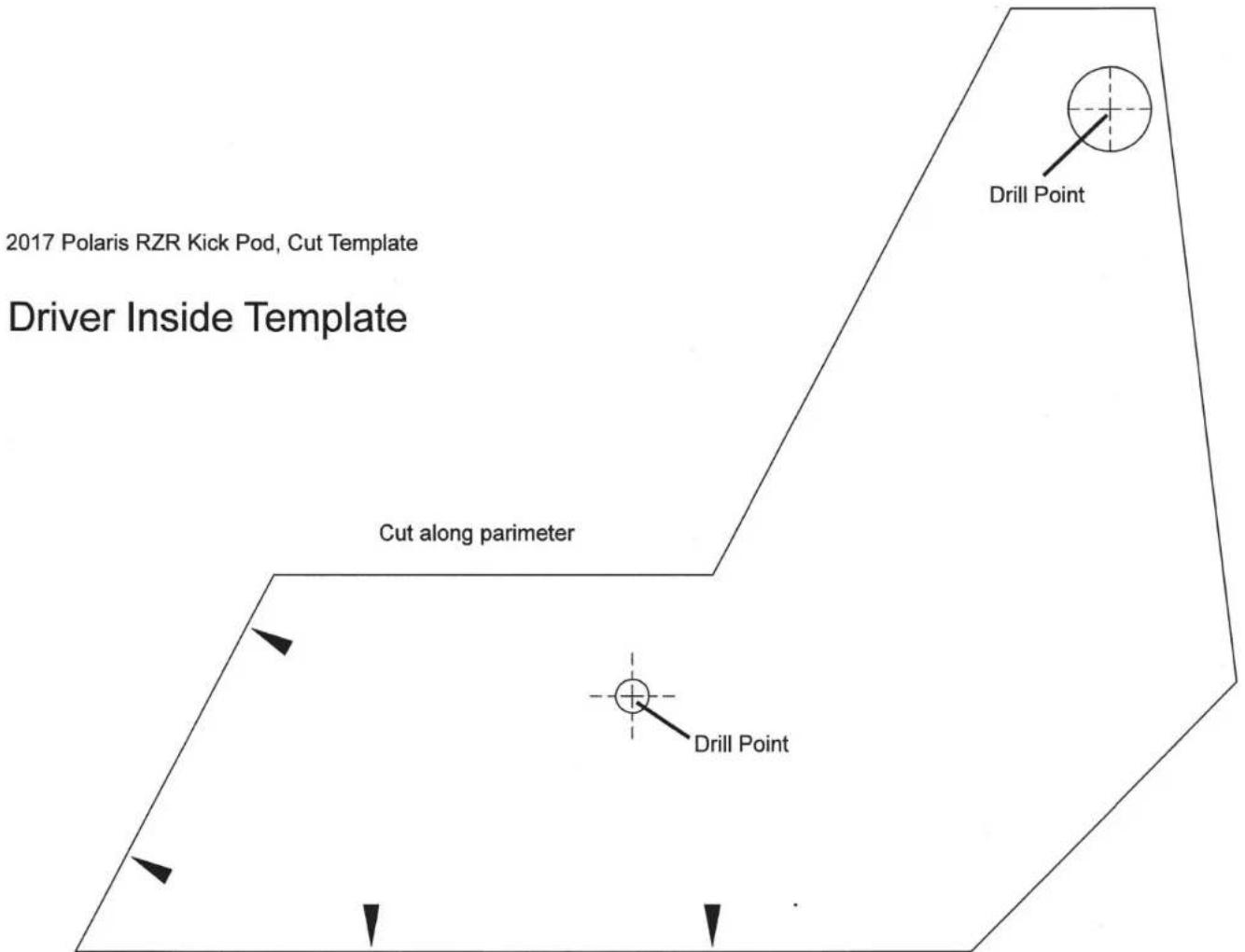
text_image
2017 Polaris RZR Kick Pod, Cut Template Driver Inside Template Cut along parameter Drill Point Drill PointCONNECTING POWER & GROUND CABLE TO BATTERY
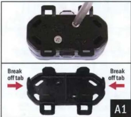
text_image
Break off tab Break off tab A1A1. Remove the bottom cover of the fuse holder by extracting the 2 screws. Break off the right and left side tabs on the bottom cover.
natural_image
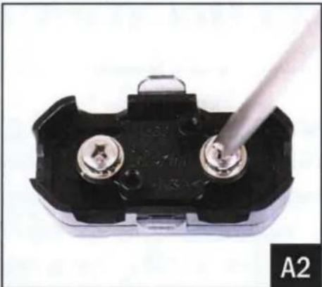
Close-up of a black electrical component with two metallic pins and a metal screwdriver inserted (no visible text or symbols)A2. Extract both fuse holder screws.
text_image
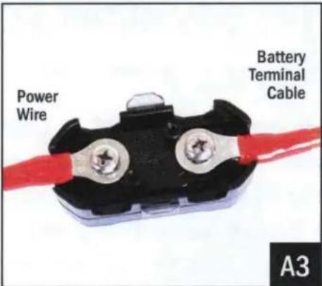
Power Wire Battery Terminal Cable A3A3. Attach both the Power Wire and Battery Terminal Cable to the fuse holder. Reattach the bottom cover.
text_image
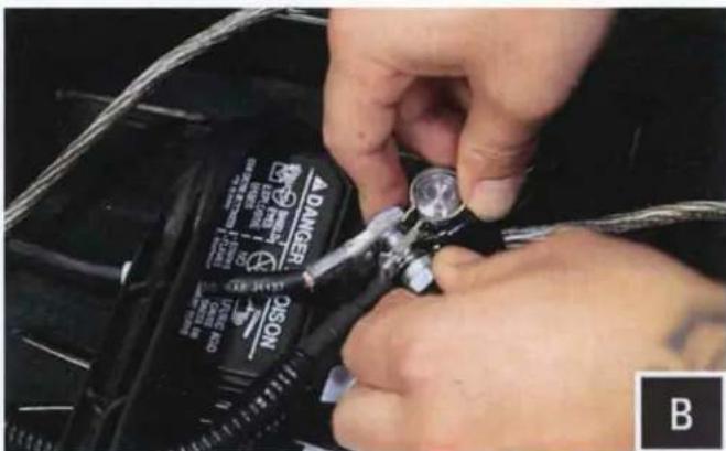
DANGER ONION BB. Unscrew the factory nut on the negative battery terminal. Install the 2 ground cables to the screw on the ground battery terminal. Re-install the factory nut.
natural_image
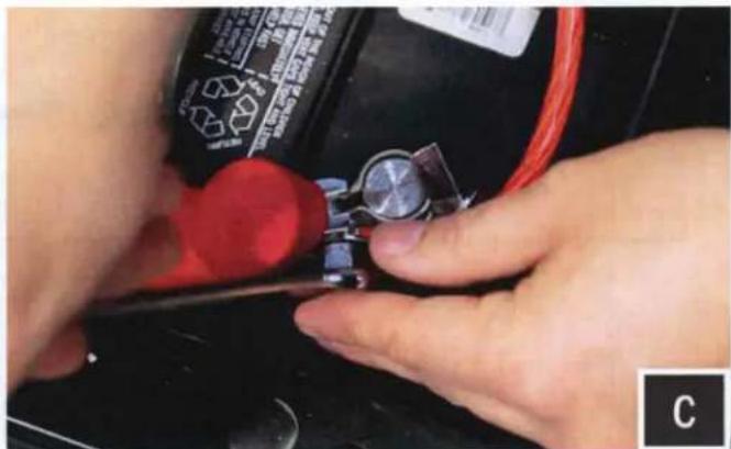
Close-up of hands using a tool to adjust or install a small component on a black battery (no visible text or symbols)C. Unscrew the factory nut on the positive battery terminal. Install the 2 power cables to the screw on the positive battery terminal. Re-install the factory nut.
natural_image
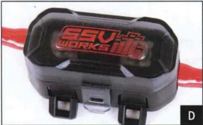
Close-up of a black and red SSV WORKS connector device with mounting brackets (no visible text or symbols on body)D. Remove the top of the fuse holder and extract the 2 screws. Insert the 40A fuse, screw the 2 screws back in and reattach the fuse holder top.

natural_image
Close-up of hands adjusting a mechanical component with a tool (no visible text or symbols)E. Zip tie all of the electrical cabling (factory and audio) along the center column away from the drive shaft.
THIS CONCLUDES THE INSTALLATION PROCESS. REPLACE THE FACTORY PANELS AND SEATS. QUESTIONS? PLEASE CONTACT SSV WORKS AT 818-991-1778 OR EMAIL SUPPORT@SSVWORKS.COM
LOOKING FOR MORE SOUND?
TRY SSV WORKS CAGE MOUNT 6.5" SPEAKER PODS!
SSV Works custom molded Cage Mount Pods are designed for 6.5" speakers and can be used when you need more sound in your Side by Side. Unlike wakeboard towers, these mini pods are designed to provide sound to the passengers without blocking visibility. They are 100% fiberglass for the best sound quality and bass response. They are finished in a black texture coat to match factory interior textures and can be custom painted to match your color scheme. - Includes the versatility of Axia Alloys patented clamping system and stainless mounting hardware. Even better, they can be loaded with either Kicker or SSV Works powersports 6.5" speakers.
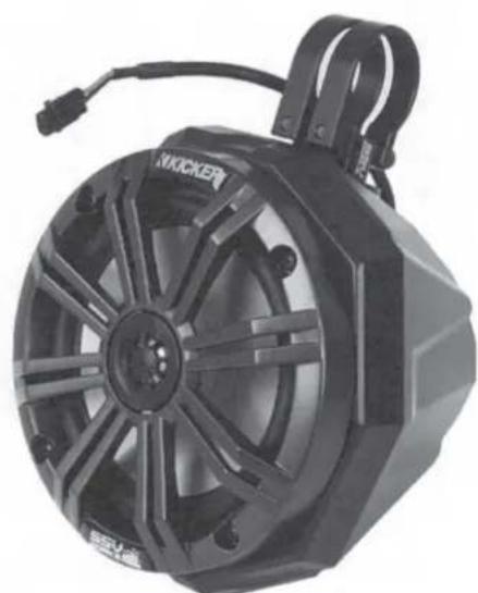
natural_image
Black Kicker electric motor with visible hub and mounting bracket (no text or symbols)Call 818-991-1778 to order yours today!
Part Number US2-C65-K