99-3019B - Kit voiture Metra - Free user manual and instructions
Find the device manual for free 99-3019B Metra in PDF.

| Product Type | Vehicle Installation Kit |
| Brand | Metra |
| Model | 99-3019B |
| Category | Car Kit |
| Dimensions (L x W x H) | 7.5 x 5.5 x 1.5 inches |
| Weight | 0.5 lbs |
| Material | ABS Plastic |
| Finish | Textured Black |
| Compatible Vehicles | Select Ford, Lincoln, Mercury models |
| Includes | Mounting brackets, screws, installation instructions |
| Installation Location | Dashboard (Double DIN or Single DIN with pocket) |
| Recommended Use | Aftermarket radio installation |
| Maintenance | Wipe with dry cloth; avoid harsh chemicals |
| Safety | Ensure secure fit to prevent vibration; follow manual |
| Spare Parts | Contact manufacturer for replacement screws or brackets |
Frequently Asked Questions - 99-3019B Metra
User questions about 99-3019B Metra
0 question about this device. Answer the ones you know or ask your own.
Ask a new question about this device
Download the instructions for your Kit voiture in PDF format for free! Find your manual 99-3019B - Metra and take your electronic device back in hand. On this page are published all the documents necessary for the use of your device. 99-3019B by Metra.
USER MANUAL 99-3019B Metra
INSTALLATION INSTRUCTIONS FOR PART 99-30198
Chevrolet Malibu (excluding Malibu limited) 2016-up 99-3019B
KIT FEATURES
• ISO DIN radio provision with pocket
- Painted matte black

natural_image
Interior view of a car dashboard with digital display and control buttons (no visible text or symbols)KIT COMPONENTS
- A) Radio trim panel • B) Radio housing • C) Radio brackets • D) Pocket • E) (10) #8 x 3/8" Phillips screws
ABCDE

natural_image
Technical line drawings of various electronic components including a plastic housing, internal casing, and screw packages (no text or symbols present)WIRING & ANTENNA CONNECTIONS (sold separately)
Wiring Harness: Please visit metraonline.com for specific interface options Antenna Adapter: 40-EU55
Table of Contents
Dash Disassembly 2
Kit Assembly
- ISO DIN radio provision with pocket......3
TOOLS REQUIRED
- Panel removal tool
- Phillips screwdriver
- 9/32" socket wrench • Cutting tool
CAUTION! All accessories, switches, climate controls panels, and especially air bag indicator lights must be connected before cycling the ignition. Also, do not remove the factory radio with the key in the on position, or while the vehicle is running.

99-3019B
Dash Disassembly
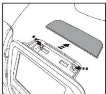
- Unclip and remove the small trim panel above the factory radio display, and then remove (2) 9/32" screws exposed. (Figure A)
- Unclip and remove the trim panel below the climate controls that extend across the dash, and above the glove box. (Figure B)
- Unclip and remove the climate controls. (Figure C)
- Inside a small cavity located behind the climate controls, remove (2) 9/32" screws facing up that are securing the radio assembly. (Figure D)
- Unclip and remove the radio assembly. (Figure E)
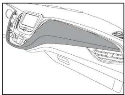
- Cut and remove the shaded area from the sub-dash to allow clearance for the aftermarket radio. (Figure F)
Continue to Kit Assembly
natural_image
Diagram of a car interior showing a door, seat, and directional arrows indicating movement or force (no text or symbols)(Figure A) (Figure B) (Figure C)

natural_image
Line drawing of a car interior showing dashboard, steering wheel, and dashboard (no text or symbols)
natural_image
Interior view of a car dashboard with a mounted touchscreen device (no visible text or symbols)
natural_image
Line drawing of a car interior showing dashboard, steering wheel, and air vent (no text or symbols)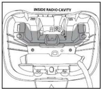
text_image
INSIDE RADIO CAVITY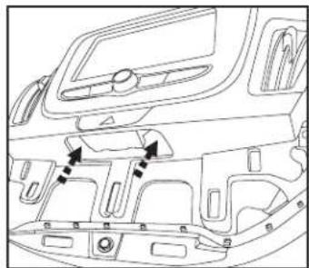
natural_image
Line drawing of a car interior showing dashboard, steering wheel, and structural components (no text or symbols)(Figure D) (Figure E) (Figure F)

99-30198
Kit Assembly
ISO DIN radio provision with pocket
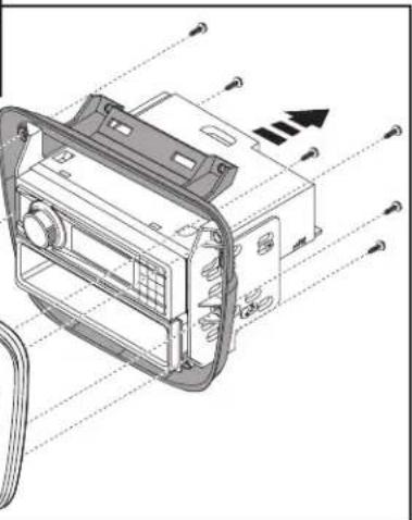
- Secure the pocket to the radio brackets using the (4) #8 x 3/8" Phillips screws provided. (Figure A)
- Remove the metal DIN sleeve and trim ring from the aftermarket radio.
- Secure the radio to the radio brackets using the screws supplied with the radio. (Figure A)
-
Slide the radio/pocket/bracket/assembly in between the radio trim panel and the radio housing and secure with the (6) #8 x 3/8" Phillips screws provided. (Figure B)
-
Locate the factory wiring harness and antenna connector in the dash, and complete all necessary connections to the radio. Metra recommends using the proper mating adapter from Metra and/or AXXESS. Test the radio for proper operation.
- Reassemble the dash in reverse order of disassembly.

text_image
Technical diagram of an electronic device with labeled ports and components(Figure A)

natural_image
Technical line drawing of a device casing with mounting holes and internal components (no text or symbols)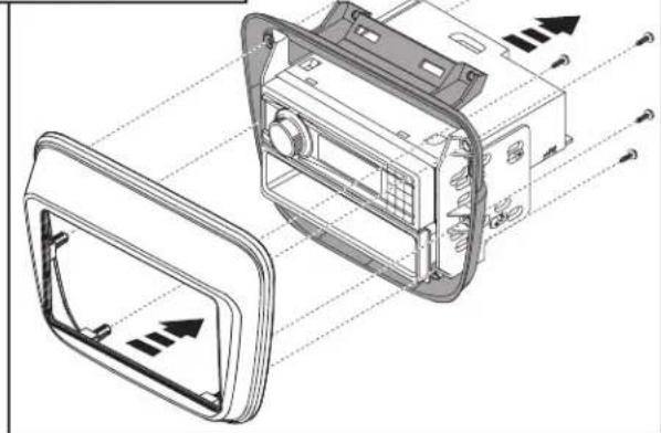
natural_image
Technical illustration of a car dashboard with internal components and directional arrows indicating flow or movement (no text or symbols present)(Figure B)

INSTALLATION INSTRUCTIONS FOR PART 99-3019B

IMPORTANT
If you are having difficulties with the installation of this product, please call our Tech Support line at 1-800-253-TECH. Before doing so, look over the instructions a second time, and make sure the installation was performed exactly as the instructions are stated. Please have the vehicle apart and ready to perform troubleshooting steps before calling.

KNOWLEDGE IS POWER
Enhance your installation and fabrication skills by enrolling in the most recognized and respected mobile electronics school in our industry. Log onto www.installerinstitute.com or call 800-354-5782 for more information and take steps toward a better tomorrow.

Metra recommends MECP certified technicians
natural_image
Interior view of a car dashboard with digital display and control buttons (no visible text or symbols)COMPONENTES DEL KIT
natural_image
Technical line drawings of electronic components including a plastic housing, internal casing, and screw assembly (no text or symbols)natural_image
Diagram of a car interior showing a door, seat, and directional arrows indicating movement or force (no text or symbols)(Figura A) (Figura B) (Figura C)
natural_image
Line drawing of a car interior showing dashboard, steering wheel, and dashboard controls (no text or symbols)
natural_image
Interior view of a car dashboard with a mounted touchscreen device (no visible text or symbols)
natural_image
Line drawing of a car interior showing dashboard, steering wheel, and air vent (no text or symbols)
natural_image
Line drawing of a car interior showing dashboard, steering wheel, and structural components (no text or symbols)(Figura D) (Figura E) (Figura F)

99-30198
Ensamble del kit
text_image
Technical diagram of an electronic device with labeled ports and components(Figura A)
natural_image
Technical line drawing of a device casing with mounting holes and internal components (no text or symbols)
natural_image
Technical illustration of a car dashboard with internal components and directional arrows indicating flow or movement (no text or symbols present)(Figura B)
Móvil (Mobile Electronics
Certification Program, MECP).