39500CRFZ909R - Sewing machine Union Special - Free user manual and instructions
Find the device manual for free 39500CRFZ909R Union Special in PDF.

User questions about 39500CRFZ909R Union Special
0 question about this device. Answer the ones you know or ask your own.
Ask a new question about this device
Download the instructions for your Sewing machine in PDF format for free! Find your manual 39500CRFZ909R - Union Special and take your electronic device back in hand. On this page are published all the documents necessary for the use of your device. 39500CRFZ909R by Union Special.
USER MANUAL 39500CRFZ909R Union Special
Supplement to catalog No. 103 QA
STYLES
39500 CRFZ-909R
Adjusting instructions and illustrated parts list
CLASS 39500 -
SINGLE NEEDLE THREE THREAD OVEREDGE MACHINE FOR METERED ELASTIC INSERTION

natural_image
Abstract black-and-white graphic resembling a stylized letter 'U' with no text or symbolsFinest Quality
Union Special® Industrial Sewing Equipment
| DETAIL NO. | PART NUMBER | DESCRIPTION | QTY. |
| 1 | 35086 D | Shaft | 2 |
| 2 | 999-81 D | ball Bearing | 2 |
| 3 | 96253 | Retaining Ring | 1 |
| 4 | 35086 EB | Roller | 1 |
| 5 | |||
| 6 | 35086 U | Washer | 1 |
| 7 | 99316 | Screw | 5 |
| 8 | 35086 GB | Roller | 6 |
| 9 | 35086 A-1 | Pin | 3 |
| 10 | 35086 V | Stop | 1 |
| 11 | 35086 W | Support Bracket | 1 |
| 12 | 99617 S | Bushing | 1 |
| 13 | 999-230 L | Bushing | 2 |
| 14 | 35086 T | Lever | 1 |
| 15 | 35086 Q | Gear | 2 |
| 16 | 35086 RB-1 | Plate | 1 |
| 17 | 999-233 C | Timing Belt | 1 |
| 18 | 99309 B | Nut | 2 |
| 19 | 35086 RB | Belt Guard | 1 |
| 20 | 99275 | Screw | 1 |
| 21 | 95167 DV | Screw | 3 |
| 22 | V90233 WC | Motor Assembly | 1 |
| 23 | 35086 N | Flange | 1 |
| 24 | 35086 PA | Gear | 1 |
| 25 | 35086 M | Flange | 1 |
| 26 | 35086 R | Belt Guard | 1 |
| 27 | 999-233 B | Toothed Belt | 1 |
| 28 | 35086 BA | Bushing | 1 |
| 29 | 90233 SC | Flip Switch | 1 |
| 30 | 35086 G | Roller | 2 |
| 31 | 35086 F | Shaft | 1 |
| 32 | 35086 E | Roller | 1 |
| 33 | 99316 | Screw | 5 |
| 34 | 35086 K | Cover | 1 |
| 35 | 35086 B | Tape Guide | 1 |
| 36 | 22738 B | Screw | 7 |
| 37 | 99697 P | Leaf Spring | 1 |
| 38 | 95959 | Washer | 2 |
| 39 | 99669 ML | Lower Knife | 1 |
| 40 | 22738 C | Screw | 2 |
| 41 | 35086 BC | Washer | 3 |
| 42 | 99670 ML | Upper Knife | 1 |
| 43 | 35086 BD | Retainign Ring | 1 |
| 44 | 35086 BG | Lever | 1 |
| 45 | 35086 BJ | Roller | 1 |
| 46 | 35086 BK | Connection | 1 |
| 47 | 95294 | Nut | 1 |
| 48 | 95167 CV | Screw | 2 |
| 49 | 999-191 H | Cylinder | 1 |
| 50 | 95166 D | Screw | 1 |
| 51 | 96904 | Washer | 1 |
| 52 | 22894 Y | Screw | 5 |
| 53 | 999-81 S | Spring Shim | 1 |
| 54 | 95303 | Screw | 3 |

text_image
Technical diagram of a mechanical assembly with numbered components and labeled partsPNEUMATIC PRESSER FOOT LIFTER
REF. NO.
| 1. | 671-A-1 |
| 2. | RM-3512-1 |
| 3. | RM-3211-2 |
| 4. | RM-3540-A |
| 5. | 39555-U |
| 6. | 22528 |
| 7. | 22653-D-8 |
| 8. | 39555-AB |
| 9. | 22644-K-40 |
| 10. | 652-20 |
| 11. | 671-F-81-C |
PART NO.
| 671-A-1 |
| RM-3512-1 |
| RM-3211-2 |
| RM-3540-A |
| 39555-U |
| 22528 |
| 22653-D-8 |
| 39555-AB |
| 22644-K-40 |
| 652-20 |
| 671-F-81-C |
DESCRIPTION
| AIR CYLINDER |
| GROMMENT |
| NUT |
| ROD END |
| THRUST PIECE |
| SCREW |
| SCREW |
| BRACKET FOR AIR CYLINDER |
| SCREW |
| WASHER |
| AIR FITTING ELBOW |

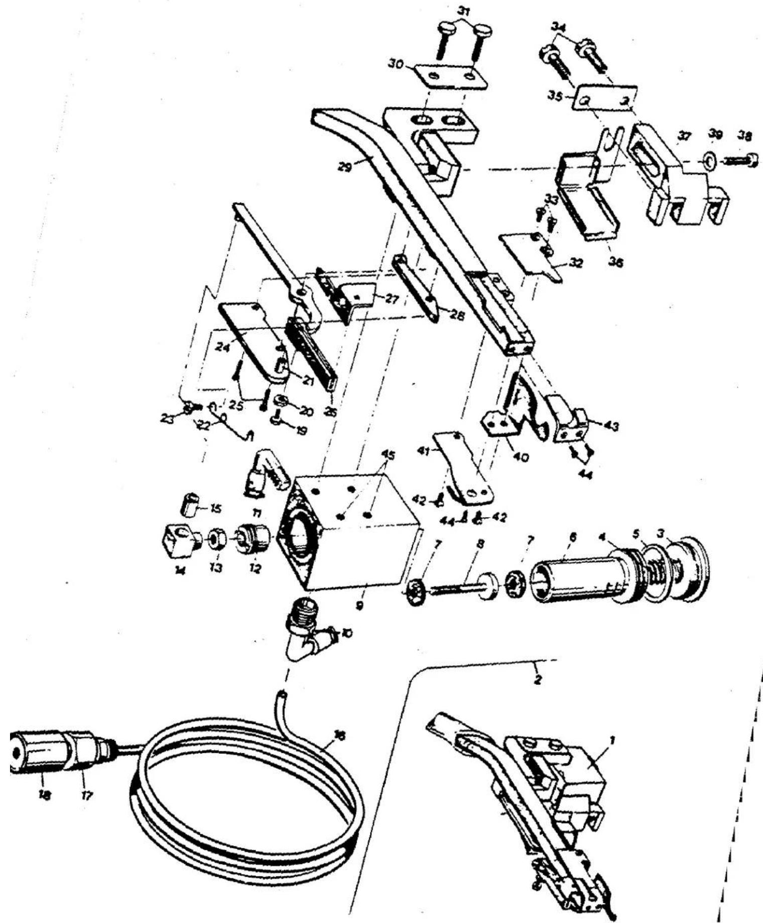
text_image
Technical diagram of a mechanical device with numbered components for identificationREF. NO.
| 1. | V-29941-AA |
| 2. | 671-H-1 |
| 3. | 671-H-1D |
| 4. | 660-753 |
| 5. | 671-H-1F |
| 6. | 671-H-1A |
| 7. | 671-H-1H |
| 8. | 39536-DC |
| 9. | 671-H-1B |
| 10. | 671-F-81-A |
| 11. | 671-F-82-C |
| 12. | 671-H-1E |
| 13. | 41071-G |
| 14. | 39573-AC |
| 15. | 671-H-1G |
| 16. | 671-B-37-B |
| 17. | 999-126-G |
| 18. | 999-140-C |
| 19. | 22588-K |
| 20. | 60078-Z |
| 21. | 39536-DB |
| 22. | 99697-DB |
| 23. | 22825 |
| 24. | 99663-MD |
| 25. | 22738-A |
| 26. | 39573-AB |
| 27. | 99669-KH |
| 28. | 99663-MC |
| 29. | 99676-MC |
| 30. | 95910-A |
| 31. | 906 |
| 32. | 99670-LH |
| 33. | 22716 |
| 34. | 99373-C |
| 35. | 95910-B |
| 36. | 39534-RB |
| 37. | 99663-KB |
| 38. | 22729-D |
| 39. | 80265 |
| 40. | 99665 |
| 41. | 99664-C |
| 42. | 22716 |
| 43. | 99677-HD |
| 44. | 22716-A |
| 45. | 12935-A |
PART NO.
DESCRIPTION
| POWER AIR_KLIPP ASSEMBLY |
| AIR MOTOR ASSEMBLY |
| PLUG SCREW |
| SPRING |
| RUMBER BUMPER |
| VIBRATOR |
| SHOCK WASHER |
| STUD |
| HOUSING |
| AIR FITTING |
| AIR FITTING |
| PLUG SCREW |
| NUT |
| DRIVE LINK |
| BUSHING |
| TUBING |
| UNION-PIECE |
| MUFFLER |
| LOWER KNIFE ADJ. SCREW |
| NUT |
| PIN |
| TORSION SPRING |
| SCREW |
| COVER PLATE |
| SCREW |
| KNIFE LEVER |
| LOWER KNIFE, marked "GS" |
| SPACER PLATE |
| TUBE ASSEMBLY |
| WASHER PLATE |
| SCREW |
| UPPER KNIFE, marked "GT" |
| SCREW |
| SCREW |
| WASHER PLATE |
| OIL SHIELD |
| BRACKET |
| SCREW |
| WASHER |
| FABRIC GUARD |
| LOOPER THREAD GUIDE |
| SCREW |
| INLET PART, marked "GV" |
| SCREW |
| SET SCREW |
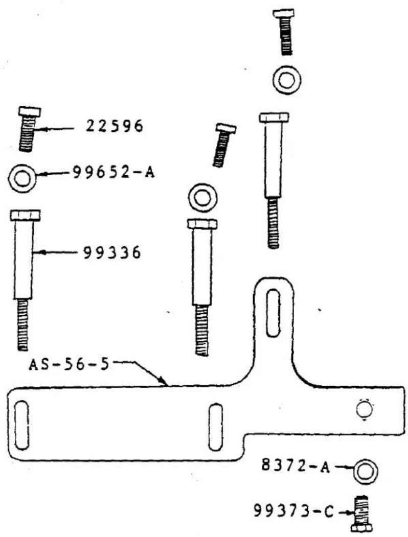
text_image
Technical diagram of a mechanical assembly with numbered components and exploded view, likely for engineering or manufacturing documentation.REF. NO.
| 1. | 39580-BA |
| 2. | 39580-E |
| 3. | GA-39524-C-5/32 |
| 4. | 39550-T |
| 5. | 88-B |
| 6. | 39582-BS |
| 7. | 22585-G |
| 8. | 39525D |
| 9. | AS-56-17 |
| 10. | 90 |
| 11. | 39505-P |
| 12. | AS-56-16 |
| 13. | AS-56-14 |
| 14. | 39540-B-7 |
| 15. | 39582-BE |
| 16. | 605-A |
| 17. | 39556-H |
| 18. | 39556-T |
| 19. | 39530-AH |
| 20. | AS-56-19 |
| 21. | AS-56-15 |
| 22. | AS-22-6 |
| 23. | 141 |
| 24. | 39521-H |
| 25. | 39503-A |
| 26. | 99677-HA |
| 27. | AS-56-9 |
| 28. | 39578-AH |
PART NO.
DESCRIPTION
| THROAT PLATE SUPPORT BRACKET |
| SHIM FOR 39580-BA |
| THROAT PLATE |
| LOWER KNIFE HOLDER |
| SCREW FOR 39550-T |
| OIL SHIELD |
| SCREW FOR 39552-BS |
| FRONT NEEDLE GUARD |
| REAR NEEDLE GUARD |
| SCREW FOR NEEDLE GUARDS |
| MAIN FEED DOG |
| DIFFERNTIAL FEED DOG |
| CHAINING FEED DOG |
| FEED DRIVE ECCENTRIC |
| SIDE COVER |
| SCREW FOR 39556-H |
| PRESSER FOOT HOLD DOWN |
| PRESSER ARM |
| PRESSER FOOT SHANK |
| UPPER KNIFE CLAMP STUD |
| EYELET (HEAD COVER) |
| SYNCHRONIZER MOUNTING WIRE |
| SCREW FOR AS-22-6 |
| HANDWEELE |
| EDGE GUIDE |
| OPTIONAL AIR-KLIPP INLET |
| PRESSER FOOT ASSEMBLY |
| CHIP GUARD |
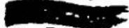
text_image
22596 99652-A 99336 AS-56-5 8372-A 99373-CCATALOG NO.
Adjusting instructions and illustrated parts list
STYLES
WS-42900-VE-2A
WS-42800-VE-2C1
WS-42800-VE-2K
WS-42800-VE-2G1
WS-42800-VE-2G2
WS-42800-VE-2H1
WS-42800-VE-2P2
CLASS 39500 -
SINGLE NEEDLE THREE THREAD OVEREDGE MACHINE FOR METERED ELASTIC INSERTION

natural_image
Pure diagram of a U-shaped object with internal curved lines, no text or symbols presentFinest Quality
Union Special Industrial Sewing Equipment

IDENTIFICATION OF MACHINES
Each UNION SPECIAL machine is identified by a Style number which on this Class machine is stamped into the Style plate affixed to the right rear of the machine. Serial number is stamped in the extension of bed casting at the right rear base of machine.
STYLES OF MACHINES
39500 CRFZ-909R - Single needle, 3-thread overedge machine with electric metering device and integral knife for elastic cut-off.
APPLICATION OF CATALOG
This catalog is a supplement to Catalog No. 103 QA and should be used in conjunction therewith. It contains the different parts used on Style 39500 CRFZ-909R.
SETTINGS
Lubrication, needles and settings see catalog No. 103 QA.
TABLE OF CONTENTS
SECTION 1 ...... GENERAL DESCRIPTION
SECTION 2 ...... INSTALLATION (UNPACKING, ELECTRICAL, AIR, SEW HEAD, ELASTIC)
SECTION 3 ...... PART LIST, ASSY. DRAWINGS
SECTION 4 PNEUMATIC DIAGRAMS
SECTION 1
GENERAL DESCRIPTION
DESCRIPTION
WS42800-VE-2 Automatic continuous elastic insertion workstation primarily used on swimwear garments. Workstation includes electric elastic pull-off device, electronic program box, needle positioner motor, tabling, and a 39500 CRP2-909R head, which comes equipped with a electronic metering device. The metering device has 3 different pre-tension selections controlled by switches on the electronic box. Pre-tension selections can be called upon by a knee press switch. Trimming is actuated by the operator by means of a small toggle switch within easy reach. After completion of the sewing cycle, the power Air-Klipp trims the chain. Healing the treadle raises the presser foot and at the same time inserts a preselected amount of elastic under the presser foot for the next garment.
1. SPECIFICATIONS
| Sewing Machine - - - - - - - - - - - - - - - - - - - - - - - - - - - - - - - - - - - - - - - - - - - - - - - - - - - - - - - - - - - - - - - - - - - - - - - - - - - - - - - - - - - - - - - - - - - - - - - - - - - - 39500CEFZ-909R |
| Stitch Type and Seam Spec. - - - - - - - - - - - - - - - - - - - - - - - - - - - - - - - - - - - - - - - - - - - - - - - - - - - - - - - - - - - - - - - - - - - - - - - - - - - - - - - - - - - - - - - - - - - - - - - - - - - |
| Stitch Range - - - - - - - - - - - - - - - - - - - - - - - - - - - - - - - - - - - - - - - - - - - - - - - - - - - - - - - - - - - - - - - - - - - - - - - - - - - - - - - - - - - - - - - - - - - - - - - - - - -7-15 S.P.I. |
| Standard Setting - - - - - - - - - - - - - - - - - - - - - - - - - - - - - - - - - - - - - - - - - - - - - - - - - - - - - - - - - - - - - - - - - - - - - - - - - - - - - - - - - - - - - - - - - - - - - - - - - - - .7 S.P.I. |
| Standard Needle - - - - - - - - - - - - - - - - - - - - - - - - - - - - - - - - - - - - - - - - - - - - - - - - - - - - - - - - - - - - - - - - - - - - - - - - - - - - - - - 154-GAS-70/027 |
| Standard Width of Bite - - - - - - - - - - - - - - - - - - - - - - - - - - - - - - - - - - - - - - - - - - - - - - - - - - - - - - - - - - - - - - - - - - - - - - 5/32" |
| Standard Max. Width of Elastic - - - - - - - - - - - - - - - - - - - - - - - - - - - - - - - - - - - - - - - - - - - - - - - - - - - - - - - - - - - - - - - - - - - - - - - - - - - - - - - - - - - - - - - - - - - - - - - - - - - - Standard Factory Pulley Size -- - 90 MM. (6,000 R.P.M.) |
2. ELECTRICAL DATA
| WS-42800-VE-A | = 220V 1 Phase, 50 Hz, 3/4 HP Motor |
| WS-42800-VE-C1 | = 220V 1 Phase, 60 Hz, 3/4 HP Motor |
| WS-42800-VE-K | = 240V 1 Phase, 50 Hz, 3/4 HP Motor |
| WS-42800-VE-2H1 | = 220V 3 Phase, 60 Hz, 3/4 HP Motor |
| WS-42800-VE-2G1 | = 220V 3 Phase, 50 Hz, 3/4 HP Motor |
| WS-42800-VE-2G2 | = 380V 3 Phase, 50 Hz, 3/4 HP Motor |
| WS-42800-VE-2P2 | = 440V 3 Phase, 50 Hz, 3/4 HP Motor |
3. PNEUMATIC
| Working Pressure - | 60 P.S.I. |
| Air Consumption - | C.F.M. |
4. OPTIONS
Part #2899-D-9-D - Waste Disposal Kit. (Kit includes all Pneumatic hardware for easy installation)
Part #AS-56-28 - 1" Max. width presser foot
SECTION 2
INSTALLATION
UNPACKING AND INSTALLATION:
- Remove the strapping. Pull out all nails holding carton to pallet and remove carton from pallet.
- Make a visual inspection to check for any obvious damage on sewing machine and tabling.
- Remove strapping holding sewing head to table.
- Take out thread stand and assemble per assembly drawing. (See parts list, Section 3.) Install stand on right rear corner of table.
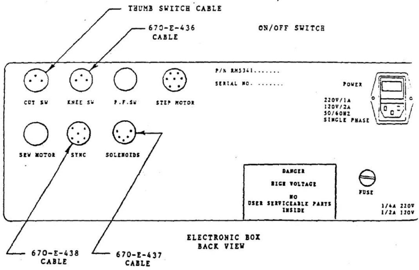
- Install electronic box and platform to control box support (support mounting location is right front corner of tabletop). Plug in cables. (See electronic box diagram).
- Install tape pull-off device into support flange mounted on rear middle portion of table and secure with socket head cap screw. Slide rod for holding elastic rolls into hole in upper bracket of stand and secure with socket head cap screw.
ELECTRICAL HOOK-UP
- Hook up electric. NOTE: See Electrical Data, Section 1, for proper workstation ordered for electrical requirements.
- Connect synchronizer cable to back of electronic box if not already done.
- Remove any remaining packing cartons, tape, etc., from sewing head.
- Toe on treadle SLOWLY and check for proper rotation of crankshaft.
AIR PRESSURE HOOK-UP
- Connect workstation to air supply at the filter regulator.
.2. Set main regulator at 60 P.S.I. - With electric off, adjust Air-Klipp regulator to 22 P.S.I. and Venturi regulator to 25 P.S.I. while holding treadle valve toed to run position.
- Treadle adjustment should be made with electric power on. Treadle valve is to open simultaneously or before motor is turning the pulley.
SEWING HEAD
- Check oil level (see Catalog 103 QA).
- Thread all eylets of machine (see )
- Check for proper stitches per inch.
- Check for proper stitch formation (see Catalog 103 QA).
- Air-Klipp adjustments (see supplement).
- Presser foot height (see supplement).
ELASTIC
- Pull-off device guides should center elastic left to right on rollers.
- Insert elastic through rollers and into metering device (see Diagram)
- Presser foot guides (left, right) adjust right guide for desired width between edge of elastic and edge of seam. Adjust left guide for proper width of elastic. NOTE: Do not let elastic pinch between guides.
MOTOR CONTROL BOX

text_image
Technical diagram of a device assembly with numbered parts and labeled components- POSITIONING SPEED ADJUSTMENT (180 R.P.M. MAX.)
- RAMP SPEED ADJUSTMENT (FACTORY SET)
- MAX MOTOR R.P.M. ADJUSTMENT (3400 R.P.M.) NOTE: PEAK MOTOR TO PREVENT EXCESSIVE WEAR ON CLUTCH.
- FOOTLIFT CABLE PLUG-IN
- MOTOR CABLE PLUG-IN
- SYNCHRONIZER PLUG-IN
RM-5341 CONTROL BOX ASSEMBLY WS-42800-VE SWIMWEAR WORKSTATIONS
PROGRAMMING
- Push "F", then program 4. (1-9).
- Push "A", "B", and/or "C" for sequence of tensions. If only one or two tensions is required then push "O". When finished Push "E".
- Enter count for "A". All 3 digits must be entered. For Example: 5 is entered as 005. Push "E" when done (Do not enter all "0").
- Repeat above for "B" and "C".
- Enter count for initial insert (2 digits to 99). Push "E" when done.
- Enter pull back compensation at start (2 digits to 99). Push "E" when done.
- Display will blank for 3-4 seconds. Program is ready to run.
NOTE: To review a program, Push "F", then the #. Continue to Push "E" until display goes blank.
PROGRAM "O"
Program "0" contains common information shared by all programs. To change.
- Push "F", then program # "0".
- Enter the number of stitches (00-99) for the air miser at the start to shut off after start of sew. Push "E" when done.
- Enter the Motor Speed for inserting the elastic. (3 digits 000 to 999) This number is the time in milliseconds between steps of the motor). Push "E" when done.
- Enter the number of stitches (00-99) for the air miser at the end to turn on after the cut switch. Push "E" when done.
- Enter the of stitches at start before metering device feeds. (0-9).
- Display will blank for 3-4 seconds and return to previous PGM that was selected.
DIRECT RUNNING OF PROGRAM
- Push "D".
- Enter program #.
- Display will blank and go directly to program selected.
RM-5341 CONTROL BOX ASSEMBLY
WS-42800-VE SWIMWEAR WORKSTATIONS
SERVICE/RUN
Service mode disables all input switches (PF, Thumb, and Knee) for working on sewing head (Threading, etc). To disable stepping motor turn unit off in back of box with black switch near power cord. Run mode will reload previous program # selected.
TYPICAL SETTINGS
Air miser start = 30
Motor Speed = 050
Air miser final = 00
Feed count = 1
Sequence = AB
A = 015 for raw rubber flat
B = 100 for 2 to 1
= 150 for 3 to 1
Initial insert = 40-45
Pull back = 2-5
cc: G. Gilbson
D. Navlyt
D. Ford
F. Jaudas
R. Deitz

text_image
TO ELECTRONIC CONTROL BOX BLACK RED GREEN BLUE GREEN 670-C-B1-D BARRIER.TUMPER TO ELASTIC RULL-OFF DEVICE GNR RLX RED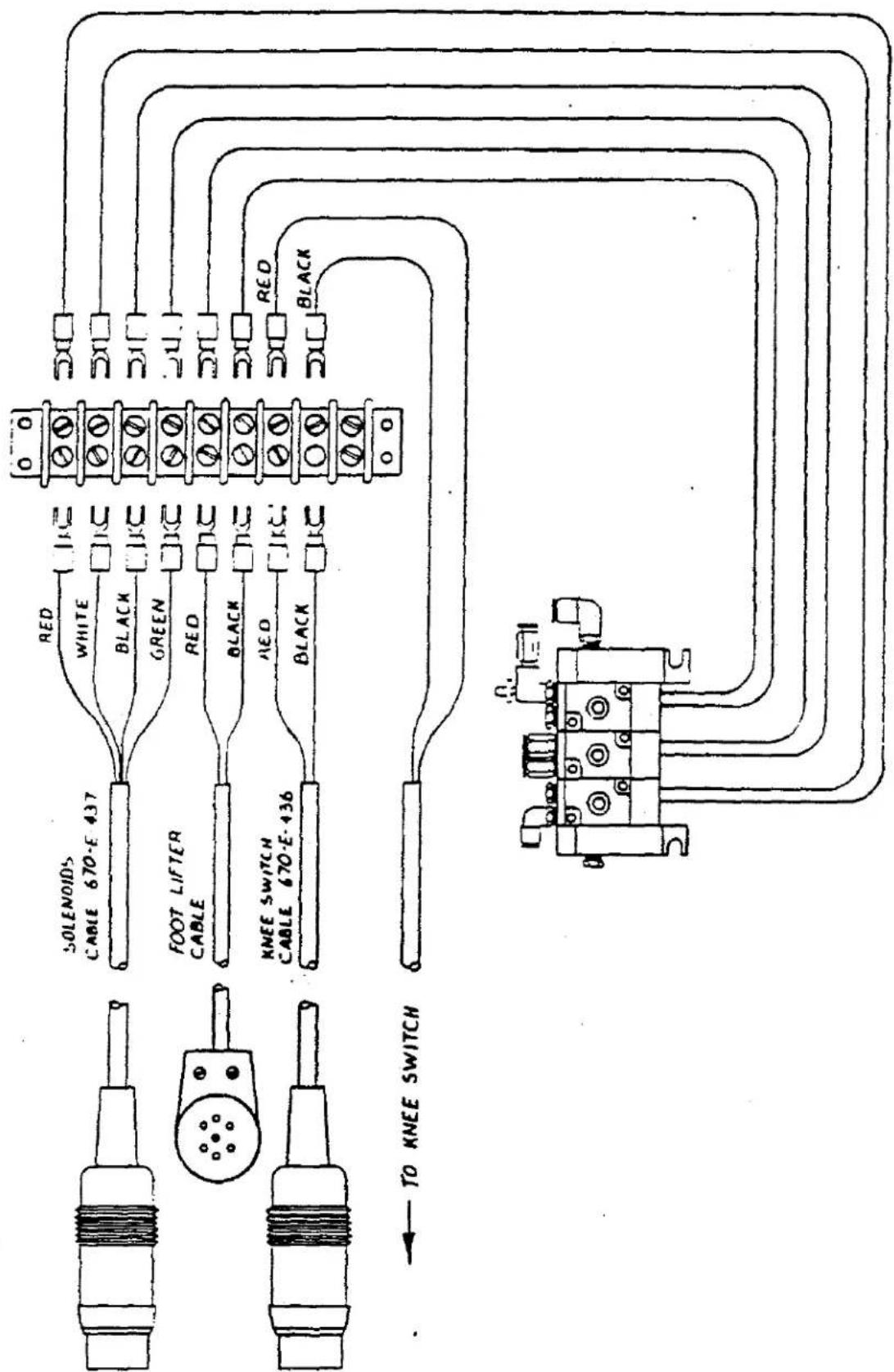
text_image
TO KNEE SWITCH KNEE SWITCH 670-3.436 RGB RGB RGB RGB RGB RGB RGB RGB RGB RGB RGB RGB RGB RGB RGB RGB RGB RGB RGB RGB RGB RGB RGB RGB RGB RGB RGB RGB RGB RGB RGB RGB RGB RGB RGB RGB RGB RGB RGB RGB RGB RGB RGB RGB RGB RGB RGB RGB RGB RGB 850105
text_image
A-039 B-054 C-35 UnionSpecial POWER A B C SERVICE RUN O 1 2 3 4 5 6 7 8 9 A E C D E FELECTRONIC BOX FRONT VIEW
text_image
THUMB SWITCH CABLE ON/OFF SWITCH 670-E-436 CABLE P/N RM5341...... SERIAL NO...... POWER 220V/1A 120V/2A 50/60Hz SINGLE PHASE CUT SW KNEE SW P.F.SW STEP MOTOR SEV MOTOR SYNC SOLENOIDS DANGER HIGH VOLTAGE NO USER SERVICEABLE PARTS INSIDE FUSE 1/4A 220V 1/2A 120V 670-E-438 CABLE 670-E-437 CABLE ELECTRONIC BOX BACK VIEW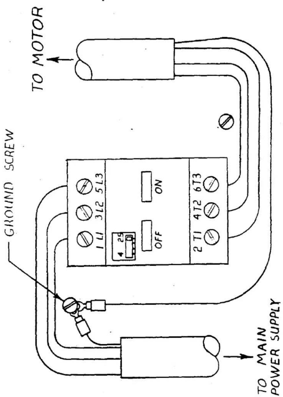
text_image
TO MOTOR GROUND SCREW 2 11 4 12 6 13 ON OFF 25 1 11 3 12 5 13 TO MAIN POWER SUPPLY
text_image
Technical diagram of a mechanical assembly with numbered components and labeled partsTHREAD STAND ASSEMBLY
THREAD STAND ASSEMBLY
| DETAIL NO. | DESCRIPTION | QTY. |
| 1 | Thread Stand Base | 1 |
| 2 | Screw | 1 |
| 3 | Nut | 1 |
| 4 | Thread Stand Rod (Lower) | 1 |
| 5 | Bracket | 1 |
| 7 | Spool Pin | 3 |
| 8 | Spring Washer | 3 |
| 9 | Nut | 3 |
| 10 | Spool Tray | 3 |
| 11 | Seat | 3 |
| 12 | Spool Retaining Fig | 3 |
| 13 | Screw | 1 |
| 14 | Washer | 1 |
| 15 | Screw | 1 |
| 16 | Thread Stand Rod (Upper) | 1 |
| 17 | Joint | 1 |
| 18 | Screw | 2 |
| 19 | Nut | 2 |
| 20 | Holder (Large) | 1 |
| 21 | Thread Guide Bar | 1 |
| 22 | Screw | 1 |
| 23 | Nut | 1 |
| 24 | Screw | 1 |
| 25 | Nut | 1 |
| 26 | Holder (Small) | 1 |
| 27 | Screw | 1 |
| 28 | Nut | 1 |
| 32 | Thread Guide Bar | 1 |
| 34 | Screw | 1 |
| 35 | Nut | 1 |
| 36 | Bracket | 1 |
| 38 | Thread Eyelet | 1 |
| 39 | Screw | 3 |
| 40 | Washer | 1 |
| 41 | Screw | 1 |
| 42 | Cap | 1 |
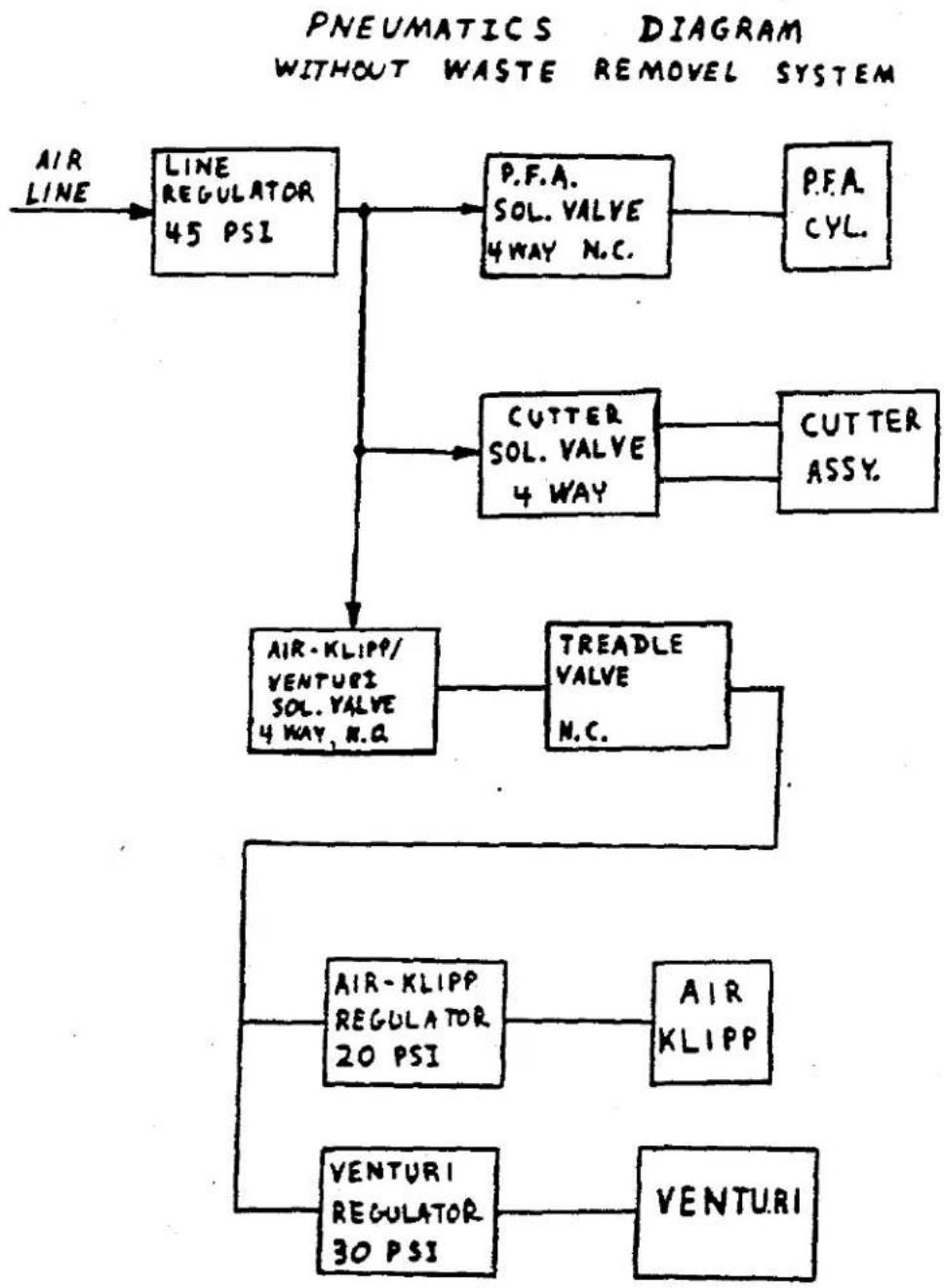
flowchart
graph TD
    A["AIR LINE"] --> B["LINE REGULATOR 45 PSI"]
    B --> C["P.F.A. SOL. VALVE 4 WAY N.C."]
    C --> D["P.F.A. CYL."]
    B --> E["CUTTER SOL. VALVE 4 WAY"]
    E --> F["CUTTER ASSY."]
    B --> G["AIR-KLIPP/VENTURI SOL. VALVE 4 WAY N.Q."]
    G --> H["TREADLE VALVE N.C."]
    H --> I["AIR-KLIPP REGULATOR 20 PSI"]
    I --> J["AIR KLIPP"]
    G --> K["VENTURI REGULATOR 30 PSI"]
    K --> L["VENTURI"]
flowchart
graph TD
    A["FOOT LIPT"] --> B["CHAIN VENTURI"]
    B --> C["DETAIL 3"]
    C --> D["AIR KLIPP MOTOR"]
    D --> E["DETAIL 2"]
    E --> F["TREADLE ROD AF"]
    F --> G["DETAIL 5"]
    G --> H["DETAIL 1"]
    H --> I["AIR INLET"]
    I --> J["KNIFE CVL."]
    J --> K["①"]
    K --> L["②"]
    L --> M["③"]
    M --> N["④"]
    N --> O["⑤"]
    O --> P["⑥"]
    P --> Q["⑦"]
    Q --> R["⑧"]
    R --> S["⑨"]
    S --> T["⑩"]
    T --> U["⑪"]
    U --> V["⑫"]
    V --> W["⑬"]
    W --> X["⑭"]
    X --> Y["⑮"]
    Y --> Z["⑯"]
    Z --> A
    style A fill:#f9f,stroke:#333
    style B fill:#ccf,stroke:#333
    style C fill:#cfc,stroke:#333
    style D fill:#fcc,stroke:#333
    style E fill:#cff,stroke:#333
    style F fill:#ffc,stroke:#333
    style G fill:#cfc,stroke:#333
    style H fill:#fcc,stroke:#333
    style I fill:#ffc,stroke:#333
    style J fill:#cfc,stroke:#333
    style K fill:#fcc,stroke:#333
    style L fill:#cfc,stroke:#333
    style M fill:#fcc,stroke:#333
    style N fill:#cfc,stroke:#333
    style O fill:#cfc,stroke:#333
    style P fill:#cfc,stroke:#333
    style Q fill:#cfc,stroke:#333
    style R fill:#cfc,stroke:#333
    style S fill:#cfc,stroke:#333
    style T fill:#cfc,stroke:#333
    style U fill:#cfc,stroke:#333
    style V fill:#cfc,stroke:#333
    style W fill:#cfc,stroke:#333
    style X fill:#cfc,stroke:#333
    style Y fill:#cfc,stroke:#333
    style Z fill:#cfc,stroke:#333
PNEUMATIC DIAGRAM WITHOUT WASTE DISPOSAL
PARTS LIST
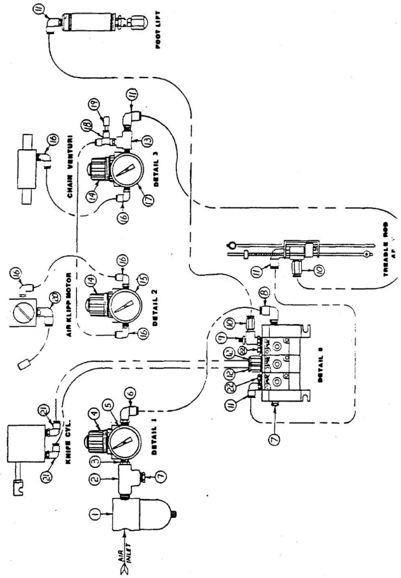
| REF. NO. | PART NUMBER | DESCRIPTION | QTY. |
| 1 | 671 D-5 | Air Filter | |
| 2 | 671 F-13 | 1/4" Tee | |
| 3 | RM-3320-1 | Reducing Nipple | |
| 4 | 671 D-10 | 100 PSI Gauge | |
| 5 | RM-3110 D | Regulator | |
| 6 | 671 F-81 C | 1/4 T. 1/8 N.P.T. Elbow | |
| 7 | 671 F-87 | 1/4 Pipe Plug | |
| 8 | 671 F-81 A | 1/4 T. 1/4 N.P.T. Elbow | |
| 9 | 671-106 B | Flow Control | |
| 10 | 671 F-81 D | 1/4 T. 1/8 N.P.T. Connector | |
| 11 | 671 F-81 C | 1/4 T. 1/8 N.P.T. Elbow | |
| 12 | 671 F-82 A | 5/32 T. 1/8 N.P.T. Connector | |
| 13 | RM-2850 D | Tee | |
| 14 | 671 D-9 | Regulator | |
| 15 | 671 D-22 | 30 P.S.I. Gauge | |
| 16 | 671 F-82 C | 5/32 T. 1/8 N.P.T. Elbow | |
| 17 | 671 D-15 | 60 P.S.I. Gauge | |
| 18 | 671 F-82 E | #5/32 T. 1/8 N.P.T. Tee | |
| 19 | 671 F-89 A | Push-In Plug | |
| 20 | 671 F-81 A | 1/4 T. 1/4 N.P.T. Elbow | |
| 21 | 671 F-82 F | 5/32 T. 10/32 N.P.T. Elbow | |
| 22 | RM-2947-1 | 1/8 Pipe Plug |
PNEUMATICS DIAGRAM
WITH WASTE REMOVEL SYSTEM
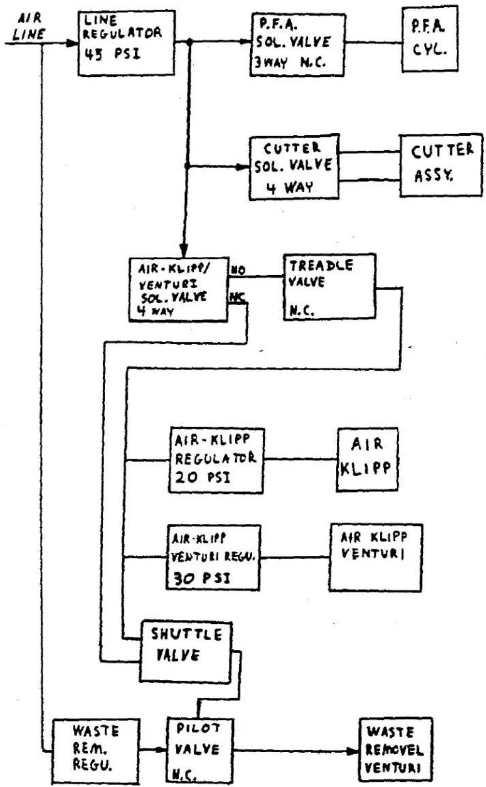
flowchart
graph TD
    A["AIR LINE"] --> B["LINE REGULATOR 45 PSI"]
    B --> C["P.F.A. SOL. VALVE 3 WAY N.C."]
    C --> D["P.F.A. CYC."]
    B --> E["CUTTER SOL. VALVE 4 WAY"]
    E --> F["CUTTER ASSY."]
    B --> G["AIR-KLIPP/VENTURI SOL. VALVE 4 WAY"]
    G --> H["TREADLE VALVE N.C."]
    G --> I["AIR-KLIPP REGULATOR 20 PSI"]
    I --> J["AIR KLIPP"]
    G --> K["AIR-KLIPP VENTURI REGU. 30 PSI"]
    K --> L["AIR KLIPP VENTURI"]
    G --> M["SHUTTLE VALVE"]
    M --> N["WASTE REM. REGU."]
    M --> O["PILOT VALVE N.C."]
    O --> P["WASTE REMOVEL VENTURI"]
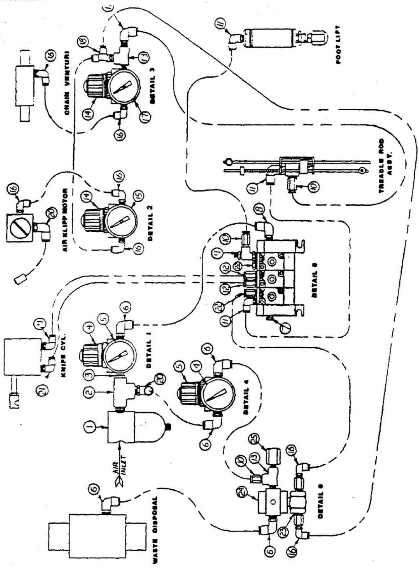
flowchart
graph TD
    A["CHAM VENTURI"] --> B["DETAIL 3"]
    B --> C["FOOT LIFT"]
    D["AIR KLIPP MOTOR"] --> E["DETAIL 2"]
    E --> F["TREADLE ROD ASSV."]
    G["KNIFE CVL"] --> H["DETAIL 1"]
    H --> I["DETAIL 4"]
    J["WASTE DISPOSAL"] --> K["DETAIL 5"]
    K --> L["DETAIL 6"]
    M["AIR INLET"] --> N["DETAIL 4"]
    N --> O["DETAIL 5"]
    P["DETAIL 6"] --> Q["DETAIL 7"]
    Q --> R["DETAIL 8"]
PARTS LIST
| REF. NO. | PART NUMBER | DESCRIPTION | QTY. |
| 1 | 671 D-5 | Air Filter | |
| 2 | 671 F-13 | 1/4" Tee | |
| 3 | RM-3320-1 | Reducing Nipple | |
| 4 | 671 D-10 | 100 PSI Gauge | |
| 5 | RM-3110 D | Regulator | |
| 6 | 671 F-81 C | 1/4 T. 1/8 N.P.T. Elbow | |
| 7 | 671 F-87 | 1/4 Pipe Plug | |
| 8 | 671 F-81 A | 1/4 T. 1/4 N.P.T. Elbow | |
| 9 | 671-106 B | Flow Control | |
| 10 | 671 F-81 D | 1/4 T. 1/8 N.P.T. Connector | |
| 11 | 671 F-81 C | 1/4 T. 1/8 N.P.T. Elbow | |
| 12 | 671 F-82 A | 5/32 T. 1/8 N.P.T. Connector | |
| 13 | RM-2850 D | Tee | |
| 14 | 671 D-9 | Regulator | |
| 15 | 671 D-22 | 30 P.S.I. Gauge | |
| 16 | 671 F-82 C | 5/32 T. 1/8 N.P.T. Elbow | |
| 17 | 671 D-15 | 60 P.S.I. Gauge | |
| 18 | 671 F-82 E | \#5/32 T. 1/8 N.P.T. Tee | |
| 19 | 671 F-89 A | Push-In Plug | |
| 20 | 671 F-81 A | 1/4 T.. 1/4 N.P.T. Elbow | |
| 21 | 671 F-82 F | 5/32 T. 10/32 N.P.T. Elbow | |
| 22 | RM-2947-1 | 1/8 Pipe Plug | |
| 23 | 671-20 | Shuttle Valve | |
| 24 | RM-4098-1 | Pilot Valve | |
| 25 | RM-3315 | Regulator Stud |
MISCELLANEOUS REPLACEMENT PARTS
| PART NUMBER | DESCRIPTION |
| 21101 W-3 | Thread Stand |
| 21233 JW | Light Fixture Assy. |
| 21233 KB | Light Bulb |
| 21233 SH | Light Fixture base |
| 21261 M-370 | Belt |
| 21371 G | Table Drawer |
| 21374 BF | K-Leg Stand |
| 2899 R | Junger Pull Off N 22/34 |
| 670 B-90 | Switch Box (Siemens) |
| 670 B-99 | Knee Switch Assembly |
| 670 E-16 | Connector Cable |
| 670 E-426 | Connecting Cable |
| 670 E-436 | Knee Switch Harness |
| 670 E-437 | Solenoid Valve Harness |
| 670 E-438 | Motor Interface Cable |
| 670 E-440 | Foot Lifter Cable (VE2) |
| 670 H-49 | Efka VD552L/8831X (2P-FL) |
| 670 L-35 | Electrical Box |
| AS-56-13 | Tableboard |
| AS-56-21 | Treadle Switch Kit |
| AS-56-6 | Control Box Support |
| AS-56-7 | Control Box Platform |
| RM-5341 | Control Box Assembly |
| AS-56-1 | Pneumatics Mounting Bracket |
| 70M-5 | EFKA SYNC1+20H12ER |
PARENT NUMBER: W842000VE2H1
DESCRIPTION: SWIMWEAR WORKITATION (2008-POSITIONER)
| SEQNO | COMPONENT | QTYPER | DESCRIPTION | PARTCODE |
| 010 | 2884B4 | 1 | CONTROL BOX ASSEMBLY | P-R |
| 010 | 2884B5 | 1 | TABLE & LEG ASSEMBLY | M-R |
| 010 | 2899R1 | 1 | PULL-OFF DEVICE (SAHL) | P-R |
| 010 | 670B90 | 1 | SWITCH BOX (SIEMENS) | P-R |
| 010 | 670H49 | 1 | EFKA VDS32L/BB31X (2P-FL) | P-R |
| 010 | RM3656-16 | 1 | 57" V-BELT 3L | P-R |
| 010 | W42800-1 | 1 | WIMWEAR MACHINE ASSEMBLY | T-R |
PARENT NUMBER: 0W42800-1
DESCRIPTION: SWIMWEAR MACHINE ASSEMBLY
| NO. | COMPONENT | QTY PER | DESCRIPTION |
| 211028 | 1 | ROD | |
| 21104818 | 1 | ROD | |
| 2110489 | 2 | ROD | |
| 21173A | 1 | CONNECTION | |
| 660-716 | 3 | CABLE STAPLE | |
| 671837A | 14 | 8/32 TUBING | |
| 671837B | 10 | 1/4" NYLON TUBING | |
| 671F29 | 1 | COUPLING | |
| 671F82C | 2 | PUSH IN 5/32 TUBE FITTING | |
| 63064H1 | 2 | CONE | |
| A856-23 | 1 | CLAMPING BLOCK | |
| A856-24 | 1 | 3 POOL THREAD STAND ASSEMBLY | |
| A856-54 | 1 | CHIP CHUTE | |
| G21217A | 1 | ROD CONNECTION | |
| RM26718 | 20 | CABLE TIE | |
| RM3293-5 | 2 | #6 F.W | |
| RM3832-1 | 5 | HARNESS WRAP | |
| RM3832-2 | 3 | HARNESS WRAP | |
| 8C296 | 2 | FLAT HEAD WOOD SCREW | |
| 21371Q | 1 | TABLE DRAWER | |
| 288481 | 1 | SWIMWEAR PNEUMATIC ASSEMBLY | |
| 288482 | 1 | JUNCTION BOX ASSEMBLY | |
| 670899 | 1 | KNEE SWITCH ASSEMBLY | |
| 670E16 | 1 | CONNECTOR CABLE | |
| 670E438 | 1 | MOTOR INTERFACE CABLE (8W) | |
| C1054 | 4 | WASHER | |
| RM3293-2 | 3 | 5/16 F.W.WASHER | |
| RM3438-1 | 3 | 5/16-16 X 1 1/2 H.H.C.S | |
| RM3993-5 | 3 | 5/16 H.S.LW | |
| 8C3298 | 4 | RD HD WOOD 9C | |
| 8C330 | 3 | #12 X 1 R.H.W.S | |
| 212338H | 1 | LGT FIXT BASE | |
| 288483 | 1 | VENTURI ASSEMBLY | |
| 29480AAB | 1 | TREADLE VALVE KIT | |
| 671F81C | 1 | PUSH-IN 1/4" TUBE ELBOW | |
| 671F81D | 1 | PUSH-IN 1/4" TUBE CONNECTOR | |
| A956-27 | 1 | LITE FIXTURE (S.W.) | |
| RM2719-3 | 4 | #10 X 11/2' P.H.S.M.S. (BLTD) | |
| 8C303 | 3 | FLAT HEAD WOOD SCREW | |
| 3045013 | 1 | SHIPPING SUPPORT STRAP | |
| 6-151-24-1 | 1 | PALLET (WS) | |
| 6-151-24-2 | 1 | SHIPPING CARTON (W/S) | |
| 6-151-24-3 | 2 | 2X4 BRACE 36' LONG |
PARENT NUMBER: 288481
| SEQNO | COMPONENT | QTYPER |
| 010 | 22840M32 | 5 |
| 010 | 40-50 | 5 |
| 010 | 860-478 | 2 |
| 010 | 860-763 | 2 |
| 010 | 670E436 | 1 |
| 010 | 670E437 | 1 |
| 010 | 670E440 | 1 |
| 010 | 671-103A | 3 |
| 010 | 671-104A | 1 |
| 010 | 671-108B | 1 |
| 010 | 671-20 | 1 |
| 010 | 671D10 | 1 |
| 010 | 671D15 | 1 |
| 010 | 671D22 | 1 |
| 010 | 671D40 | 1 |
| 010 | 671D5 | 1 |
| 010 | 671D9 | 2 |
| 010 | 671F13 | 1 |
| 010 | 671F81A | 2 |
| 010 | 671F81C | 9 |
| 010 | 671F81D | 2 |
| 010 | 671F82A | 3 |
| 010 | 671F82C | 2 |
| 010 | 671F87 | 1 |
| 010 | A856-1 | 1 |
| 010 | RM2733A | 3 |
| 010 | RM2747-2 | 3 |
| 010 | RM2791-2 | 3 |
| 010 | RM2850D | 1 |
| 010 | RM2871B | 3 |
| 010 | RM2947-1 | 1 |
| 010 | RM2951B | 1 |
| 010 | RM3110D | 2 |
| 010 | RM3289-2 | 2 |
| 010 | RM3293-3 | 5 |
| 010 | RM3315 | 5 |
| 010 | RM3320-1 | 1 |
| 010 | RM3352 | 10 |
| 010 | RM3625-3 | 1 |
| 010 | RM4098-1 | 1 |
DESCRIPTION: SWIMWEAR PNEUMATIC ASSEMBLY
| DESCRIPTION | PART CODE |
| SCREW | P-R |
| WASHER | P-H |
| LOCKNUT | P-R |
| SILENCER | P-H |
| KNEE SWITCH HARNESS | P-R |
| SOLENOID VALVE HARNESS | P-R |
| FOOT LIFTER CABLE (VE2) | P-R |
| 4 WAY SOLENOID VALVE | P-R |
| VALVE STACKING KIT | P-R |
| FLOW CONTROL | P-R |
| SHUTTLE VALVE | P-R |
| AIR PRS GAUGE | PUR |
| AIR PRS QUAGE | PUR |
| GAUGE | P-R |
| 0-100 GAUGE 1/8 BACK MOUNTED | P-R |
| AIR FILTER | P-H |
| REGULATOR | PUR |
| IMPERIAL TEE | PUR |
| PUSH-IN 1/4 TUBE FITTING | P-R |
| PUSH-IN 1/4 TUBE ELBOW | P-R |
| PUSH-IN 1/4 TUBE CONNECTOR | P-R |
| PUSH IN 5/32 TUBE FITTING | P-R |
| PUSH IN 5/32 TUBE FITTING | P-R |
| 1/4 PIPE PLUG | P-R |
| PNEUMATICS MOUNTING BRACKET | P-R |
| 6-32 x 1/2 B.H.M.S | P-R |
| #6 INTERNAL TOOTH LOCK WASHER | P-R |
| #6-32 HEX NUT | P-R |
| TEE | PUR |
| CABLE TIE | PUR |
| HEX PIPE PLUG | P-R |
| CABLE CLAMP | P-R |
| REGULATOR | P-R |
| 10-32 x 5/8 B.H.M.S | P-R |
| 3/8 F.W | PUR |
| REGULATOR STUD | P-R |
| REDUCING NIPPLE | P-H |
| SPADE TERMINAL | P-R |
| TERMINAL STRIP | P-R |
| PILOT VALVE | PUR |
PARENT NUMBER: 200482
DESCRIPTION: JUNCTION BOX ASSEMBLY
| SEQNO | COMPONENT | QTYPER | DESCRIPTION | PARTCODE |
| 010 | 660-478 | 2 | LOCKNUT | P-R |
| 010 | 660-542 | 1 | BRASS RD HD 8CR | P-R |
| 010 | 661-59 | 8 | HEYCO CONNECTOR | P-R |
| 010 | 661-59A | 1 | HEYCO CONNECTOR | P-R |
| 010 | 670E428 | 1 | CONNECTING CABLE | P-R |
| 010 | 670E488 | 1 | POWER CABLE ASSEMBLY | P-R |
| 010 | 670G61D | 2 | 3 POSITION BARRIER JUMPER | M-R |
| 010 | 670L38 | 1 | ELECTRICAL BOX | P-R |
| 010 | RM2747-2 | 2 | #6 INTERNAL TOOTH LOCK WASHER | P-R |
| 010 | RM2791-2 | 2 | #8-32 HEX NUT | P-R |
| 010 | RM2806-3 | 2 | #-32 x 3/4 &H.M.S | P-R |
| 010 | RM3625-1 | 1 | TERMINAL | P-R |
PARENT NUMBER: 288483
| SEQNO | COMPONENT | QTYPER | DESCRIPTION | PARTCODE |
| 010 | 660-536 | 1 | HOSE CLAMP | P-R |
| 010 | 671-63 | 1 | VENTURI | P-R |
| 010 | 671B11 | 1 | AIR TUBE | P-H |
| 010 | 671B12 | 1 | AIR TUBE | P-H |
| 010 | 671F81C | 1 | PUSH-IN 1/4 TUBE ELBOW | P-R |
| 010 | RM3321-2 | 1 | HOSE CLAMP ADJUSTABLE | P-R |
PARENT NUMBER: 288484
| SEQNO | COMPONENT | QTYPER |
| 010 | 22682A6 | 3 |
| 010 | A858-6 | 1 |
| 010 | A858-7 | 1 |
| 010 | BO93A | 1 |
| 010 | RM2791-1 | 4 |
| 010 | RM3293-5 | 4 |
| 010 | RM3993-4 | 7 |
| 010 | RM5341 | 1 |
DESCRIPTION: CONTROL BOX ASSEMBLY
| DESCRIPTION | CODE |
| SCREW | P-H |
| CONTROL BOX SUPPORT | P-R |
| CONTROL BOX PLATFORM | P-R |
| CARTON #26 | P-H |
| ##-32 HEX NUT | P-R |
| ## F.W | P-R |
| ## H&LLW | P-R |
| CONTROL BOX ASSEMBLY | P-R |
PARENT NUMBER: 288485
DESCRIPTION: TABLE & LEG ASSEMBLY
| SEQNO | COMPONENT | QTYPER | DESCRIPTION | PARTCODE |
| 010 | 213748F | 1 | K-LEG STAND | P-H |
| 010 | A856-13 | 1 | TABLEBOARD | P-R |
PROGRAMMING INSTRUCTIONS FOR SWIMWEAR CONTROL BOX #5341
WITH STITCH COUNTING SOFTWARE PACKAGE #VO1108
PROGRAMS: 1-9
(Note that program "0" has settings shared by programs 1-9)
CAPABILITIES OF EACH PROGRAM (1-9):
1) Choice of 1, 2 or 3 tensions.
2) Choice of tension sequence (A, A-B, A-B-C)
3.) Ability to pre-tension the elastic for an immediate gathering of material.
4.) Choice of manual or stitch-counted change (during sew).
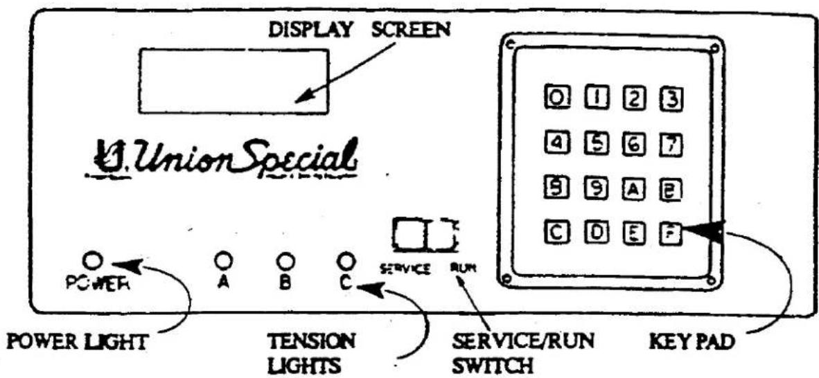
text_image
DISPLAY SCREEN UnionSpecial POWER LIGHT A B C SERVICE RUN TENSION LIGHTS SERVICE/RUN SWITCH KEY PAD| DISPLAY SCREEN | 1.) Shows current program and tension settings when sewing.2.) Shows individual functions when changing a program. |
| POWER LIGHT | Illuminated green when power is on. |
| TENSION LIGHTS | Signals operator is sewing using tension "A", "B" or "C" by illuminating red.(Light will change when tension is changed.) |
| SERVICE RUN SWITCH | Service - Control box, metering device and knee-switch are off. Sewing is possible without elastic attachment.Run - Control box, metering device and knee-switch operate as programmed. |
KEY PAD OPERATION
| ENTERING A PROGRAMCHANGE/VIEW SETTINGS("F'-KEY) | Key "F" followed by a number will enter that program to change it or to view its contents. Example - Press key "F", then "2". You are now at the first setting listed under "SETTING PROGRAMS 1-9" which is "ENTER SEQUENCE" (for program "2"). |
| CHANGING/ VIEWING SETTINGS("E"-KEY) | Once within a program (see "ENTERING A PROGRAM TO CHANGE/VIEW SETTINGS", above) you may change settings using the number keys (0-9). To lock a setting in, press key "E" (enter). The display will now move to the next setting to be changed. (If you wish to simply view the contents of a program, press "E" only, and no changes will occur. Once the last setting in the program is reached, pressing "E" will remain you to the beginning of program "1" and the box is ready to perform as programmed. |
| "D"-KEY | Used to simply "go to" a program to sew without changing it. |
| "A", "B" AND "C" KEYS | Used to change tension sequence. |
| NUMERIC KEYS(0-9) | 1.) Used following "F" and "D" keys to tell which program to go to.2.) Used to change settings within all programs. |
SETTING PROGRAMS 1-9
| TENSION SEQUENCE | Determines the order of tensions A, B and C. Also how many tensions are to be used. If only "A" is entered, tension can not change while sewing. If "A-B" is entered, tension will change from "A" to "B" to "A", etc. |
| TENSION "A" | Determines the speed of the metering device which determines how much gathering will be produced. Approximately "015" will produce flat goods. The higher the number, the more gathering. |
| TENSION "B" | See explanation of Tension "A" (above). |
| TENSION "C" | See explanation of Tension "A" (above). |
| INITIAL INSERT | How much elastic will be inserted into the presser foot when the operator heels down. The number entered is measured in 1/64". |
| FULL BACK | Used to gain immediate gathering of material. When the treadle is toed, the metering device reverses to stretch the elastic (See "PULL BACK DELAY"). |
| STITCH COUNT 'A' | Determines the amount of stitches to be sewn with tension setting "A". Once this amount has been reached, the metering device will automatically switch to the next tension in sequence (See "TENSION SEQUENCE") (NOTE- Must be set at "000" to use "COMPENSATION STEPS" in program "0") |
| STITCH COUNT 'B' | See explanation of "STITCH COUNT "A"(above). (NOTE-Must be set at "000" to use "COMPENSATION STEPS" in program "0") |
| STITCH COUNT "C" | See explanation of "STITCH COUNT "A"(above). (NOTE-Must be set at "000" to use "COMPENSATION STEPS" in program "0") |
SETTING PROGRAM "0"
| PROGRAM SEQUENCE | Determines the programs to be used in sequence to produce a garment (up to eight programs). Example - Setting "1-3-6". After the cut-switch is activated, the box jumps to program "3", then program "6", then back to program "1". |
| ENTER CODE | Enter-code "5341". This is to limit access to only those authorized. |
| AIR SAVER START | How many stitches after sew begins before the Air-Klipp and venturi shut off. |
| INITIAL INSERT. | How fast the elastic will be inserted into the presser foot when the operator heels down. |
| AIR SAVER FINAL | How many stitches after the cut-switch is activated before the Air-Klipp and venturi return on. |
| INSERT DELAY | Ensures that the presser foot has fully risen to the metering device before elastic is inserted. |
| COMPENSATION SPEED | Speed of the stepping motor when reversing or forwarding when using compensation (below). |
| COMPENSATION STEPS "AB" | Forwards or reverses the stepping motor "x" number of steps to make im mediate changes in gathering (x= number entered). Example- to go from ten sion "A" =015 to tension "B" =035, "COMPENSATION STEPS "AB" would be about "15" to "20". (NOTE-Must be set at "00" to use "STITCH COUNT" in "SETTING PROGRAMS 1-9) |
| COMPENSATION STEPS 'BC' | See explanation of "COMPENSATION STEPS 'AB'" (above). (NOTE-Must besel at '00" to use "STITCH COUNT" in "SETTING PROGRAMS 1-9" |
| COMPENSATION STEPS 'CA' | See explanation of "COMPENSATION STEPS 'AB'" (above). (NOTE-Must be set at '00" to use "STITCH COUNT" in "SETTING PROGRAMS 1-9" |
| PULL BACK DELAY | Allows stitches to be sewn before "PULL BACK" begins ( see "PULL BACK", above.). |
REMOVAL/INSTALLATION OF PROM #5387, ALL VERSIONS

text_image
(A) TOP COVER (B) FRONT PANEL (C) PROM PROM NOTCH REAR PANEL1.) Remove 4 top cover screws (A), and remove top cover.
2.) Remove 2 front panel screws (B) and unplug blue plugs (C) being cautious not to damage pins or plugs (a short, side to side pull should be sufficient). Now remove front panel
3.) Next, lay the front panel flat and locate the correct prom (see Fig. 1) and remove carefully, being cautious not to damage prom pins.
4.) Locate the notch on one side of the new prom. This notch must face in the same direction as the other proms on the board. Carefully line all of the pins onto the terminal and gently push into place.
5.) Replace blue plugs to the front panel, then re-attach the front panel and top cover for operation.
6.) See "Programming Instructions" table of contents (see swimwear catalog) to program your new prom.
Your prom was accompanied with a label to be affixed to the control box. Choose the label that matches the voltage being used and affix the label over the old part number (found on the rear panel). This is important for service information. Discard the unused label.
ORDERING PROCEDURE FOR REPAIR BOXES
Please use the following part numbers to order updated boxes for repair purposes:
RM 5387 AR (for 110 V)
RM 5387 BR (for 220 V)
IMPORTANT - Please retain these instructions for future reference.
PROGRAMMING INSTRUCTIONS FOR SWIMWEAR CONTROL BOX #5341
PROGRAMS: 1-9
(Note that program "0" has settings shared by programs 1-9)
CAPABILITIES OF EACH PROGRAM (1-9):
1.) Choice of 1, 2 or 3 tensions.
2.) Choice of tension sequence (A, A-B, A-B-C)
3.) Ability to pre-tension the elastic for an immediate gathering of material.

text_image
DISPLAY SCREEN UnionSpecial POWER LIGHT A B C TENSION LIGHTS SERVICE RUN SERVICE/RUN SWITCH KEY PAD| DISPLAY SCREEN | 1.) Shows current program and tension settings when sewing.2.) Shows individual functions when changing a program. |
| POWER LIGHT | Illuminated green when power is on. |
| TENSION LIGHTS | Signals operator is sewing using tension "A", "B" or "C" by illuminating red.(Light will change when tension is changed.) |
| SERVICE RUN SWITCH | Service - Control box, metering device and knee-switch are off. Sewing is possible without elastic attachment.Run - Control box, metering device and knee-switch operate as programmed. |
| KEY PAD OPERATION | |
| ENTERING A PROGRAM CHANGE/ VIEW SETTINGS ("F'-KEY) | Key "F" followed by a number will enter that program to change it or to view its contents. Example - Press key "F", then "2". You are now at the first setting listed under "SETTING PROGRAMS 1-9" which is "ENTER SEQUENCE" ( for program "2"). |
| CHANGING/ VIEWING SETTINGS ("E"-KEY) | Once within a program ( see "ENTERING A PROGRAM TO CHANGE/VIEW SETTINGS", above) you may change settings using the num- ber keys (0-9). To lock a setting in, press key "E" (enter). The display will now move to the next setting to be changed. (If you wish to simply view the con- tents of a program, press "E" only, and no changes will occur. Once the last set- ting in the program is reached, pressing "E" will return you to the beginning of program "1" and the box is ready to perform as programmed. |
| "D"-KEY | Used to simply "go to" a program to sew without changing it. |
| "A", "B" AND "C" KEYS | Used to change tension sequence. |
| NUMERIC KEYS (0-9) | 1.) Used following "F" and "D" keys to tell which program to go to. 2.) Used to change settings within all programs. |
SETTING PROGRAMS 1-9
| ENTER SEQUENCE | Determines the order of tensions A, B and C. Also how many tensions are to be used. If only "A" is entered, tension can not change while sewing. If "A-B" is entered, tension will change from "A" to "B" to "A", etc. |
| ENTER "A" | Determines the speed of the metering device which determines how much gathering will be produced. Approximately "015" will produce flat goods. The higher the number, the more gathering. |
| ENTER "B" | See explanation of Tension "A" (above). |
| ENTER "C" | See explanation of Tension "A" (above). |
| INITIAL INSERT | How much elastic will be inserted into the presser foot when the operator heels down. The number entered is measured in 1/64". |
| FULL BACK | Used to gain immediate gathering of material. When the tensile is used, the metering device reverses to stretch the elastic. (See "PULL BACK DELAY") |
SETTING PROGRAM "0"
| AIR SAVER START | How many stitches after sew begins before the Air-Klipp and veaturi shut off. |
| INITIAL INSERT. SPEED | How fast the elastic will be inserted into the presser foot when the operator heels down. |
| AIR SAVER FINAL | How many stitches after the cut-switch is activated before the Air-Klipp and veaturi return on. |
| FEED STITCH COUNT | Allows stitches to be sewn before "PULL BACK" begins (see "PULL BACK", above). |