MegaPix DWC-MTT4Wi36 - Surveillance Camera Digital Watchdog - Free user manual and instructions
Find the device manual for free MegaPix DWC-MTT4Wi36 Digital Watchdog in PDF.

User questions about MegaPix DWC-MTT4Wi36 Digital Watchdog
0 question about this device. Answer the ones you know or ask your own.
Ask a new question about this device
Download the instructions for your Surveillance Camera in PDF format for free! Find your manual MegaPix DWC-MTT4Wi36 - Digital Watchdog and take your electronic device back in hand. On this page are published all the documents necessary for the use of your device. MegaPix DWC-MTT4Wi36 by Digital Watchdog.
USER MANUAL MegaPix DWC-MTT4Wi36 Digital Watchdog
MEGApix® 4MP Turret IP Camera
DWC-MTT4Wi28
DWC-TT4Wi36
DWC-TT4Wi6
natural_image
Close-up of a white surveillance camera with a circular lens and 'DW' logo on the head (no text or symbols on the device itself)User's Manual Ver. 04/17
Before installing and using the camera, please read this manual carefully.
Be sure to keep it handy for future reference.
CAUTION
RISK OF ELECTRIC SHOCK. DO NOT OPEN.

CAUTION:
TO REDUCE THE RISK OF ELECTRIC SHOCK, DO NOT REMOVE COVER (OR BACK) NO USER SERVICEABLE PARTS INSIDE. REFER SERVICING TO QUALIFIED SERVICE PERSONNEL.
Warning
This symbol indicates that dangerous voltage consisting a risk of electric shock is present within this unit.
Precaution
This exclamation point symbol is intended to alert the user to the presence of important operating and maintenance (servicing) instructions in the literature accompanying the appliance.
WARNING
To prevent damage which may result in fire or electric shock hazard, do not expose this appliance to rain or moisture.
WARNING
- Be sure to use only the standard adapter that is specified in the specification sheet. Using any other adapter could cause fire, electrical shock, or damage to the product
- Incorrectly connecting the power supply or replacing battery may cause explosion, fire, electric shock, or damage to th product.
- Do not connect multiple cameras to a single adapter. Exceeding the capacity may cause excessive heat generation or fire
- Securely plug the power cord into the power receptacle. Insecure connection may cause fire
- When installing the camera, fasten it securely and firmly A falling camera may cause personal injury.
- Do not place conductive objects (e.g. screw drivers, coins, metal items, etc.) or containers filled with water on top of the camera. Doing so may cause personal injury due to fire electric shock, or falling objects.
- Do not install the unit in humid, dusty, or sooty locations. Doing so may cause fire or electric shock
- If any unusual smells or smoke come from the unit, stop using the product. Immediately disconnect the power sorce and contact the service center. Continued use in such a condition may cause fire or electric shock
- If this product fails to operate normally, contact the nearest service center. Never disassemble or modify this product in any way.
- When cleaning, do not spray water directly onto parts of the product. Doing so may cause fire or electric shock
Precaution
Operating
- Before using, make sure power supply and all other parts are properly connected.
- While operating, if any abnormal condition or malfunction is observed, stop using the camera immediately and contact your dealer.
Handling
- Do not disassemble or tamper with parts inside the camera.
- Do not drop the camera or subject it to shock or vibration as this can damage the camera.
- Clean the clear dome cover with extra care. Scratches and dust can ruin the quality of the camera image.
Installation and Storage
- Do not install the camera in areas of extreme temperature, exceeding the allowed range.
- Avoid installing in humid or dusty environments.
- Avoid installing in places where radiation is present.
- Avoid installing in places where there are strong magnetic yields and electric signals.
- Avoid installing in places where the camera would be subject to strong vibrations.
-
Never expose the camera to rain or water.
-
Read these instructions. - All safety and operating instructions should be read before installation or operation
-
Keep these instructions. - The safety, operating and use instructions should be retained for future reference.
-
Heed all warnings. - All warnings on the product and in the operating instructions should be adhered to.
-
Follow all instructions. - All operating and use instructions should be followed.
-
Do not use this device near water. - For example: near a bath tub, wash bowl, kitchen sink, laundry tub, in a wet basement; near a swimming pool; etc.
-
Clean only with dry cloth. - Unplug this product from the wall outlet before cleaning. Do not use liquid cleaners.
-
Do not block any ventilation openings. Install in accordance with the manufacturer's instructions. - Slots and openings in the cabinet are provided for ventilation, to ensure reliable operation of the product, and to protect it from over-heating. The openings should never be blocked by placing the product on bed, sofa, rug or other similar surfaces. This product should not be placed in a built-in installation such as a bookcase or rack unless proper ventilation is provided and the manufacturer's instructions have been adhere to.
-
Do not install near any heat sources such as radiators, heat registers, or other apparatus (including amplifiers) that produce heat.
-
Do not defeat the safety purpose of the polarized or grounding-type plug. A polarized plug has two blades with one wider than the other. A grounding type plug has two blades and a third grounding prong. The wide blade or the third prong are provided for your safety. If the provided plug does not fit into your outlet, consult an electrician for replacement.
-
Protect the power cord from being walked on or pinched particularly at plugs, convenience receptacles, and the point where they exit from the apparatus.
-
Only use attachments/accessories specified by the manufacturer.
-
Use only with cart, stand, tripod, bracket, or table specified by the manufacturer, or sold with the apparatus. When a cart is used, use caution when moving the cart/apparatus combination to avoid injury from tip-over.

-
Unplug the apparatus during lightning storms or when unused for long periods of time.
-
Refer all servicing to qualified service personnel. Servicing is required when the apparatus has been damaged in any way, such as power supply cord or plug is damaged, liquid has been spilled or objects have fallen into the apparatus, the apparatus has been exposed to rain or moisture, does not operate normally, or has been dropped.

Disposal of Old Appliances
-
When this crossed-out wheel bin symbol is attached to a product it means the product is covered by the European Directive 2002/96/EC.
-
All electrical and electronic products should be disposed of separately form the municipal waste stream stream in accordance to laws designated by the government or the local authorities.
-
The correct disposal of your old appliance will help prevent potential negative consequences for the environment and human health.
-
For more detailed information about disposal of your old appliance, please contact your city office, waste disposal service or the shop where you purchased the product.
FCC
This equipment has been tested and found to comply with the limits for a Class A digital device, pursuant to part 15 of the FCC Rules. These limits are designed to provide reasonable protection against harmful interference when the equipment is operated in a commercial environment. This equipment generates, uses, and can radiate radio frequency energy and, if not installed and used in accordance with the instruction manual, may cause harmful interference to radio communications. Operation of this equipment in a residential area is likely to cause harmful interference in which case the user will be required to correct the interference at his own expense.
Table of Contents
1 Product & Accessories....5
2 Parts and Description....6
3 Installation....7
4 Cabling....8
5 Remote Preview 9
6 Remote Live Surveillance....10
6.1 System Configuration....10
6.1.1 Basic Information....10
6.1.2 Date and Time.... 11
6.1.3 Local Config.... 11
6.2 Image Configuration 11
6.2.1 Display Configuration 11
6.2.2 Video / Audio Configuration 13
6.2.3 OSD Configuration....14
6.2.4 Video Mask 15
6.2.5 ROI Configuration....15
6.3 Alarm Configuration....16
6.3.1 Motion Detection 16
6.3.2 Alarm Server 18
6.4 Event Configuration....19
6.4.1 Object Removal.... 19
6.4.2 Exception 21
6.4.3 Line Crossing 22
6.4.4 Intrusion....24
6.5 Network Configuration....26
6.5.1 TCP/IP 26
6.5.2 Port....28
6.5.3 Server Configuration....28
6.5.4 DDNS 28
6.5.5 SNMP 30
6.5.6 RTSP....31
6.5.7 UPNP 31
6.5.8 Email....32
6.5.9 FTP 32
6.6 Security Configuration....33
6.6.1 User Configuration 33
6.6.2 Online User 35
6.6.3 Block and Allow Lists....35
6.7 Maintenance Configuration 35
6.7.1 Backup and Restore 35
6.7.2 Reboot 36
6.7.3 Upgrade 36
6.7.4 Operation Log....37
Record Search....38
8 Appendix....39
9 Dimensions....41
10 Warranty Information....42
11 Limits and Exclusions....43
1 Product & Accessories
natural_image
Close-up of a white surveillance camera with a circular lens and 'DW' logo (no text or symbols on the device itself)| Default Login Information | |
| Username: admin | Password: admin |
WHAT'S IN THE BOX
| QSG Manual |  | 1 Set | Tapping Screws PA 4x35 – 4pcs | 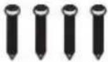 | 1 Set |
| Mounting Template |  | 1 Set | Plastic Plugs – 4pcs | 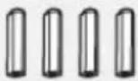 | 1 Set |
| Waterproof Cap | 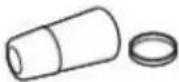 | 1 Set | Torx Wrench |  | 1 Set |
| Rubber Plug |  | 1 Set |
2 Parts and Description
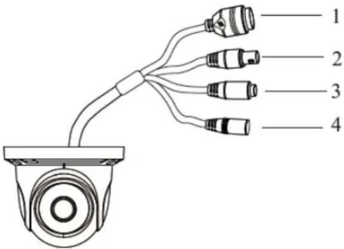
text_image
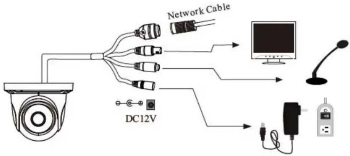
1 2 3 4| 1 | Network Cable | 3 | MIC IN Cable |
| 2 | CVBS Cable | 4 | Power Cable |
flowchart
graph TD
    A["Camera"] --> B["Network Cable"]
    A --> C["DC12V"]
    B --> D["Monitor"]
    C --> E["DC12V"]
    D --> F["Display"]
    E --> G["Monitor"]
3 Installation
-
Before installing the camera, make sure the mounting surface can bear three times the weight of your camera.
-
Do not let the cables get caught in improper places or the electric line cover to be damaged. This may cause a breakdown or fire.
-
Using the mounting template sheet or the camera itself, mark and drill the necessary holes in the wall or ceiling.
-
Pass the wires through and make all necessary connections. See cabling section for more information.
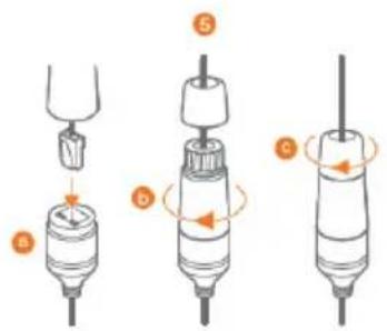
-
To use the camera's water proof wiring:
a. Install the LAN cable into 'a'.
b. 'b' will be assembled to 'a' with a 1/4 turn.
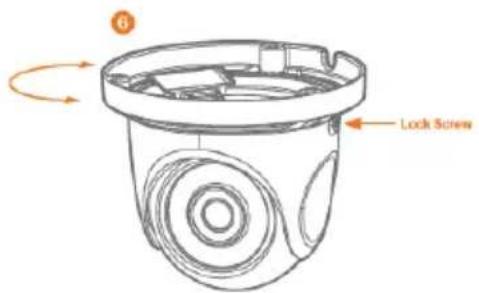
c. Thread 'c' tightly to 'b'.Adjust the camera to obtain an optimum angle by loosening the lock screws.
text_image
Diagram showing three stages of a hairpin tool with labeled parts and directional arrows indicating motion or movement.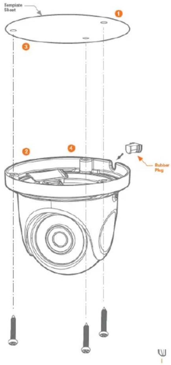
text_image
Template Shoot ① ③ ② ④ Rubber Plug-
Tighten the lock screws after you finish adjusting the view angle of the camera.
-
Remove the protection film softly to complete the installation
text_image
6 Lock ScrewNOTE: To ensure moisture seal, make sure the O-ring is in place between 'a' and 'b'. In extreme environments use of an outdoor rated sealer is recommended.
NOTE: When using the waterproof cap, crimp the RJ45 connector after passing the cable through the waterproof cap.
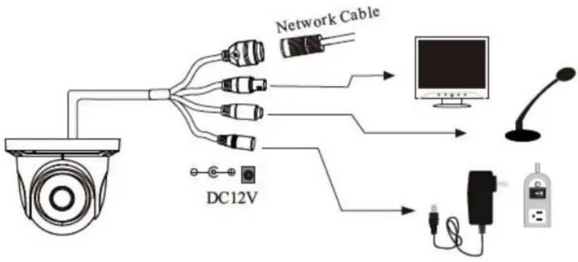
4 C a b l i n g
- NETWORK CONNECTIONS – If you are using a PoE Switch, connect the camera using an Ethernet cable for both data and power.
- NETWORK CONNECTIONS – If you are using a non-PoE switch, connect the camera to the switch using an Ethernet cable for data transmission and use a power adapter to power the camera.

text_image
Ethernet Cable Ethernet Cable PowerUse the diagram below to connect all external devices to the camera:
flowchart
graph TD
    A["Camera"] --> B["Network Cable"]
    A --> C["DC12V"]
    B --> D["Monitor"]
    C --> E["DC12V"]
    D --> F["Display"]
    E --> G["Radio"]
5 Remote Preview
To log in to the camera, open an Internet Explorer page and input the camera's IP address. If you are connecting to the camera for the first time, be sure to download the ActiveX control. After downloading, a login window will pop up as shown below.

text_image
DW DIGITAL WATCHDOG® Complete Surveillance Solutions Name: admin Password: ******** Stream Type: 2560x1440 30fps Language: English Remember me LoginInput the username and password to log in.

The default username is "admin"; the default password is "admin".
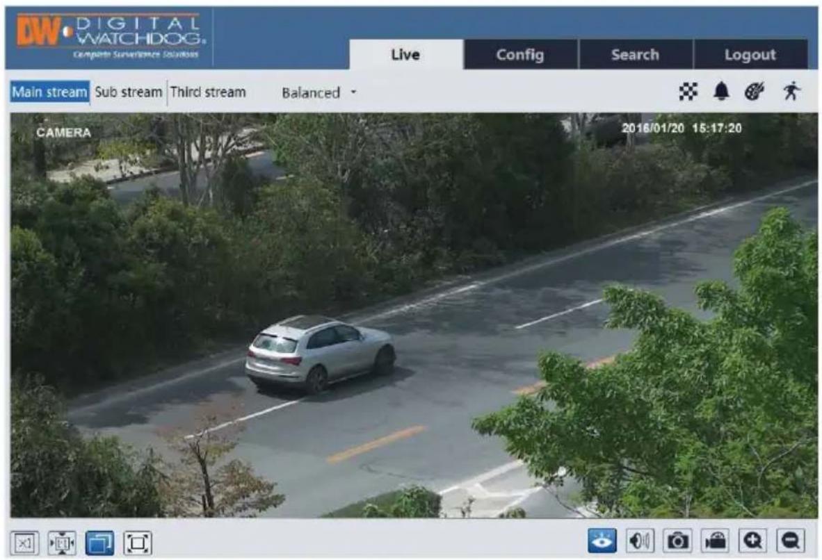
After you log in, you will see the following window.
text_image
DW DIGITAL WATCHDOG Compute Surveillance Solutions Live Config Search Logout Main stream Sub stream Third stream Balanced CAMERA 2016/01/20 15:17:20The following table is the instructions of the icons on the remote preview interface.
| Icon Description Icon Description | |||
 | Original size Scene change | indica [BW08] icon | |
 | Appropriate size Abnormal | clarity [ZXZA] icator icon | |
 | Auto Color abnormal indicator ico | [XS8D] | |
 | Full screen Motion alarm indicato | [20ZH] on | |
| [747A] | Start/stop live view Start/stop re |  ing ing | |
 | Enable/disable audio Zoom in |  | |
 | Snap Zoom out |  | |
- When motion detection alarm is triggered, the people icon will turn red.
- In full screen mode, double click to exit.
6 Remote Live Surveillance
6.1 System Configuration
The "System" configuration includes three submenus: Basic Information, Date and Time and Local Config.
6.1.1 Basic Information
In the "Basic Information" interface, you can check the relative information of the device.
| Device Type | xxxx |
| Brand | xxxx |
| Software Version | 4.1.1.0(8234) |
| Software Build Date | 2016-11-10 |
| Kernel Version | 20161109 |
| Hardware Version | 1.3 |
| Onvif Version | 2.3 |
| OCX Version | 1.1.3.5 |
| MAC | 00:18:ae:12:ab:1d |
6.1.2 Date and Time
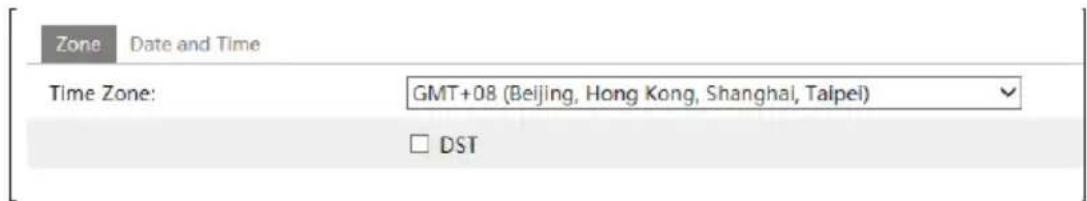
Go to Config→System→Date and Time. Please refer to the following interface.
text_image
Zone Date and Time Time Zone: GMT+08 (Beijing, Hong Kong, Shanghai, Taipei) □ DSTYou can select the time zone and DST as required.
Click "Date and Time" tab to set the time mode.
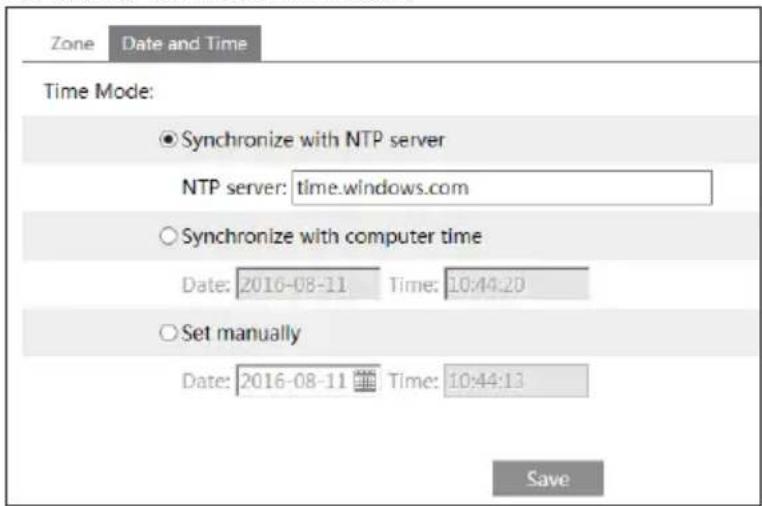
text_image
Zone Date and Time Time Mode: ● Synchronize with NTP server NTP server: time.windows.com ○ Synchronize with computer time Date: 2016-08-11 Time: 10:44:20 ○ Set manually Date: 2016-08-11 Time: 10:44:13 Save6.1.3 Local Config
Go to Config→System→Local Config. You can set the storage path of the captured pictures and video records. You can also enable or disable the video audio.
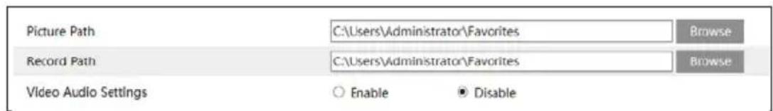
text_image
Picture Path C:\Users\Administrator\Favorites Browse Record Path C:\Users\Administrator\Favorites Browse Video Audio Settings ○ Enable ● Disable6.2 Image Configuration
Image Configuration includes Display, Video/Audio, OSD, Video Mask and ROI Config.
6.2.1 Display Configuration
Go to Image→Display interface as shown below. You may set and adjust the picture's brightness, contrast, hue and saturation, etc.

natural_image
Aerial view of a paved urban road with parked cars and surrounding greenery (no visible text or signage)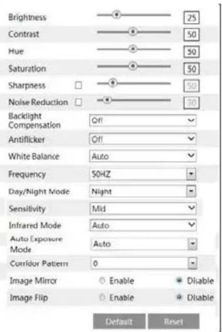
text_image
Brightness Contrast Hue Saturation Sharpness Noise Reduction Backlight Compensation Antiflicker White Balance Frequency Day/Night Mode Sensitivity Infrared Mode Auto Exposure Mode Corridor Pattern Image Mirror Image Flip Enable Enable Disable Default Reset 25 50 50 50 50 30- Brightness: Set the brightness level of the camera's image.
- Contrast: Set the color difference between the brightest and darkest parts.
• Hue: Set the total color degree of the image. - Saturation: Set the degree of color purity. The purer the color is, the brighter the image is.
- Sharpness: Set the resolution level of the image plane and the sharpness level of the image edge.
- Noise Reduction: Decrease the noise and make the image more thorough. Increasing the value will make the noise reduction effect better but it will reduce the image resolution.
• Backlight Compensation:
- Off: Close the backlight compensation function. It is the default mode. - WDR
As to the WDR scene, WDR will help the camera provide clear images when there are both very bright and very dark areas simultaneously in the field of the view by lowering the brightness of the highlight area and increasing the brightness of the lowlight area. High, middle and low can be selected.
- There will be some record lost in a few seconds during mode changing from non-WDR to WDR mode.
○ HLC: Lower the brightness of the whole image by suppressing the brightness of the image's highlight area and reducing the size of the halo area.
○ BLC: The exposure will begin automatically according to the scene for the goal of seeing the darkest area of the image.
- Anti-flicker:
• Off: Close the anti-flicker function.
- 50Hz: Make sure the horizontal stripes will not appear in the image while the device is adjusting the exposure automatically according to the brightness of the scene when the electric supply is 50Hz.
- 60Hz: Make sure the horizontal stripes will not appear in the image while the device is adjusting the exposure automatically according to the brightness of the scene when the electric supply is 60Hz.
- White Balance: Adjust the color temperature according to the environment automatically.
• Frequency: 50Hz and 60Hz can be optional.
• Day/night Mode: Please choose the mode as needed.
• Sensitivity: High, middle and low can be selected.
• Infrared Mode: You may choose "ON", "OFF" and "Auto" as required. - Exposure Mode: You may choose "Auto" or "Manual" as required.
- Corridor Pattern: You can change the direction of the video image by using this function. 0, 90, 180 and 270 are available. The default value is 0. The video resolution should be 1080P or under 1080P if you use this function.
• Image Mirror: Reverse the current video image right and left.
• Image Flip: Turn the current video image upside down.
6.2.2 Video / Audio Configuration
Go to Image→Video / Audio interface as shown below. In this interface, you can set the resolution, frame rate, bitrate type and video quality and so on subject to the actual network condition.

text_image
Video Audio Index Stream Name Resolution Frame Rate Bitrate Type Bitrate(Kbps) Video Quality I frame Interval Video Compression Profile 1 Main stream 2560x1440 30 CBR 3072 Minimum 120 H265 Main Profile 2 Sub stream 352x240 30 CBR 512 High: 120 H264 High Profile 3 Third stream 704x480 30 CBR 768 Higher 120 H264 High Profile Send Snapshot L Size: (2560x1440) □ Video encode slice split ☑ Watermark Watermark content: XXXClick "Audio" tab to go to the interface as shown below.

text_image
Video Audio Audio Encoding G711A Audio Type MIC SaveThree video streams can be adjustable.
• Resolution: The higher the resolution is, the clearer the image is.
- Frame rate: The higher the frame rate is, the more fluency the video is. However, more storage room will be taken up.
- Bitrate type: Including CBR and VBR. CBR means that no matter how changeable the video resources are, the compression bitrate keeps constant. This will not only facilitate the image quality better in a constant bitrate but also help to calculate the capacity of
the recording. VBR means that the compression bitrate can be adjustable according to the change of the video resources. This will help to optimize the network bandwidth.
- Bitrate: Please choose it according to the actual network situation.
- Video Quality: When VBR is selected, you need to choose image quality. The higher the image quality you choose, the more bitrate will be required.
- I Frame interval: It is recommended to use the default value. If the value is over high, the read speed of the group of pictures will be slow resulting in the quality loss of the video.
- Video Compression: H264 and H265 are optional. Higher quality of image can be transferred under limited network bandwidth by using H265 video encoding, however, higher quality of the hardware is required.
- Profile: Baseline, main/high profiles are optional. Baseline profile is mainly used in interactive application with low complexity and delay. Main/high profile is mainly used for higher coding requirement.
- Send Snapshot: Please select it according to the actual situation.
- Video encode slice split: If enabled, you may get more fluency image even though using the low-performance PC.
- Watermark: If enabled, input the watermark content. You may check the watermark when playing back the local record in the search interface, lest the record files is tampered.
• Audio Encoding: G711A and G711U are selectable.
• Audio Type: MIC and LIN are selectable.
6.2.3 OSD Configuration
Go to Image→OSD interface as shown below.

text_image
Date Format YYYY/MM/DD Show Timestamp Device Name name Show Device Name OSD Content1 Add One Line OSD Content2 Add One Line OSD Content3 Add One Line OSD Content4 Add One Line OSD Content5 Add One Line SaveYou may set time stamp, device name and OSD content here. After enabling the corresponding display and entering the content, drag them to change their position. Then click "Save" button to save the settings.
6.2.4 Video Mask
Go to Image→Video Mask interface as shown below. You can set 4 mask areas at most.

text_image
Enable Draw Area Clear SaveTo set up video mask:
- Enable video mask.
- Click "Draw Area" button and then drag the mouse to draw the video mask area.
- Click "Save" button to save the settings.
- Return to the live to see the following picture.

text_image
name 2016/01/12 11:53:20Clear the video mask:
Go to video mask interface and then click "Clear" button to delete the current video mask area.
6.2.5 ROI Configuration
Go to Image→ROI Config interface as shown below.

natural_image
Aerial view of two cars driving on a tree-lined road, surrounded by greenery and trees (no visible text or symbols)- Check "Enable" and then click "Draw Area" button.
- Drag the mouse to set the ROI area.
- Set the level.
- Click "Save" button to save the settings.
Now, you will see the selected ROI area is clearer than other areas especially in low bitrate condition.

natural_image
Aerial view of two white cars parked on a tree-lined road, surrounded by greenery (no visible text or symbols)6.3 Alarm Configuration
Alarm configuration includes two submenus: Motion Detection and Alarm Server.
6.3.1 Motion Detection
Go to Alarm→Motion Detection to set motion detection alarm.

text_image
Alarm Config Area and Sensitivity Schedule Enable Alarm Alarm Holding Time 5 Seconds Trigger Email Trigger FTP Save-
Check "Enable Alarm" check box to activate motion based alarm, choose alarm holding time and set alarm trigger options.
-
Trigger Email: If "Trigger Email" and "Attach Picture" checkbox is checked (email address shall be set first in the Email configuration interface), the captured pictures and triggered event will be sent into those addresses.
-
Trigger FTP: If "Trigger FTP" and "Attach Picture" checkbox is checked, the captured pictures will be sent into FTP server address. Please refer to FTP configuration chapter for more details.
-
Set motion detection area and sensitivity. Click "Area and Sensitivity" tab to go to the interface as shown below.

text_image
Alarm Config Area and Sensibility Schedule Sensitivity Low High 4 Draw Add Erase Select All Clear All Invert SaveMove the "Sensitivity" scroll bar to set the sensitivity.
Select "Add" and click "Draw" button and drag mouse to select the motion detection area; Select "Erase" and drag the mouse to clear motion detection area.
After that, click "Save" to save the settings.
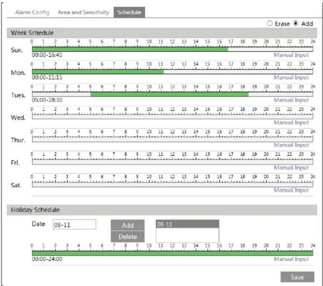
- Set the schedule of the motion detection. Click "Schedule" tab to go to the interface as shown below.
bar
| Day | Time | Event | | --------- | ----------------- | ------------ | | Sun | 00:00-16:45 | Manual Input | | Mon | 00:00-11:15 | Manual Input | | Tues | 05:00-18:30 | Manual Input | | Wed | 0 | Manual Input | | Thur | 0 | Manual Input | | Fri | 0 | Manual Input | | Sat | 0 | Manual Input | | 08-11 | 00:00-24:00 | Add | | 08-11 | 00:00-24:00 | Delete | | 08-11 | 00:00-24:00 | Erase | | 08-11 | 00:00-24:00 | Manual Input |Week schedule
Set the alarm time from Monday to Sunday for alarm every day in one week. The lengthwise means one day of a week; the rank means 24 hours of a day. Green means selected area. Blank means unselected area.
"Add": Add the schedule for a special day.
"Erase": Delete holiday schedule.
Day schedule
Set alarm time for alarm in some time of a special day, such as holiday.
Set a date at the "Date" box, click "Add" button to add that date to the list box on the right side and then drag the scroll bar to set the schedule of that day.
Select a date in the list box on the right side, and click "Delete" to remove the schedule on that day.
Click "Save" button to save the settings.
Note: Holiday schedule is prior to Week schedule.
6.3.2 Alarm Server
Go to Alarm→Alarm Server interface as shown below.
You may input the alarm server address and port. When the alarm happens, the camera will automatically transfer the alarm event to the alarm server. If the alarm server is not used, there is no need for you to configure here.
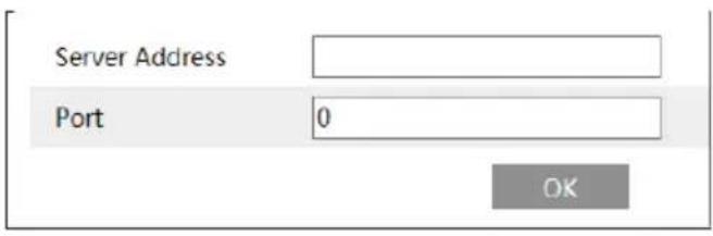
text_image
Server Address Port 0 OK6.4 Event Configuration
Event configuration includes four submenus: Object Removal, Exception, Line Crossing and Intrusion.
Note: Some software versions of this series of cameras may not support the following functions. Please take actual displayed interface as final.
6.4.1 Object Removal
To set object removal:
Go to Config→Event→Object Removal interface as shown below.
text_image
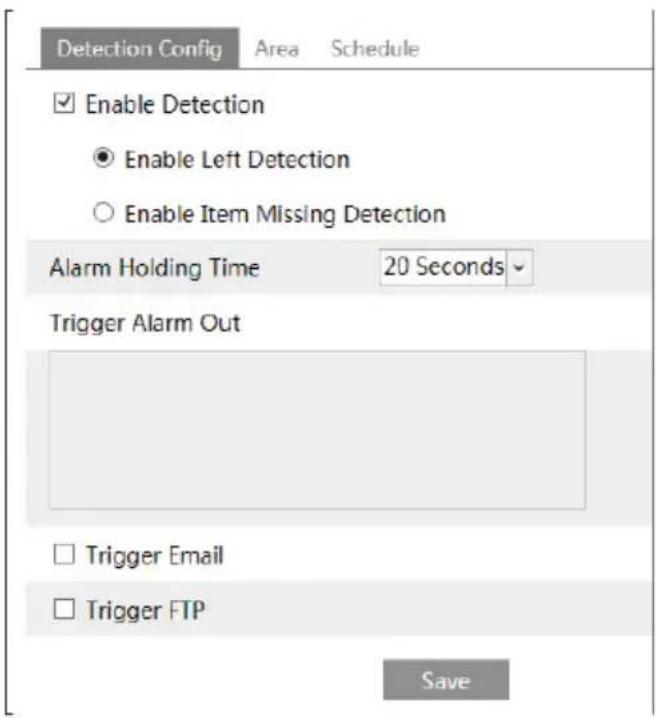
Detection Config Area Schedule Enable Detection Enable Left Detection Enable Item Missing Detection Alarm Holding Time 20 Seconds Trigger Alarm Out Trigger Email Trigger FTP Save-
Enable object removal detection and then select the detection type.
-
Enable Left Detection: The relevant alarms will be triggered if there are items left in the pre-defined alarm area.
-
Enable Item Missing Detection: The relevant alarms will be triggered if there are items missing in the pre-defined alarm area.
-
Set the alarm holding time and alarm trigger options. The setting steps are the same with that of motion detection. Please refer to motion detection chapter for details.
- Click "Save" button to save the settings.
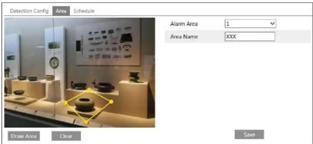
- Set the alarm area of the object removal detection. Click "Area" tab to go to the interface as shown below.
text_image
Detection Config Area Schedule Alarm Area 1 Area Name XXX Draw Area Clear SaveSet the alarm area number and then input the alarm area name on the right side. You can add 4 alarm areas at most.
Click "Draw Area" button and then click around the area where you want to set as the alarm area in the image on the left side (the alarm area should be a closed area). Click "Stop Draw" button to stop drawing. Click "Clear" button to delete the alarm area. Click "Save" button to save the settings.
- Set the schedule of the object removal detection. The setting steps of the schedule are the same with that of motion detection. Please refer to motion detection chapter for details.
※ Application Scenario Illustration
- Object removal detection cannot determine the objects' ownership. For instance, there is an unattended package in the station. Object removal detection can detect the package itself but it cannot determine whether it is an ownership package.
- Try not to enable object removal detection when light changes greatly in the scene.
- Try not to enable object removal detection if there are complex and dynamic environments in the scene.
- Adequate light and clear scenery are very important to object removal detection.
- Please contact us for more detailed application scenarios.
- Here we take some improper application scenarios for instance.
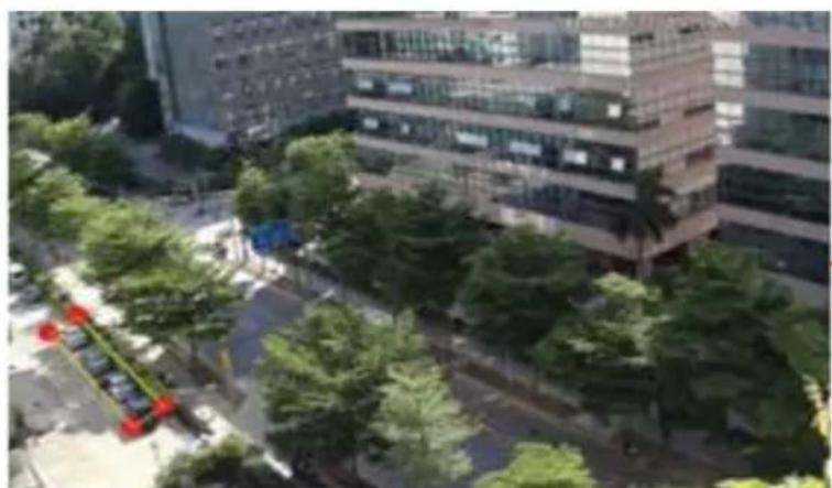
natural_image
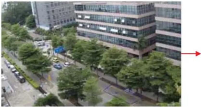
Exterior view of a modern office building with surrounding greenery and parking lot (no visible text or signage)There are so many trees near the road and cars running on the road, which make the scene too complex to detect the removal objects.
natural_image
Exterior view of a modern multi-story office building with surrounding greenery and parked cars (no visible signage or text)There are so many trees near the road and cars running on the road, which make the scene too complex to detect the removal objects.
6.4.2 Exception
To set exception detection:
Go to Config→Event→Exception interface as shown below.
text_image
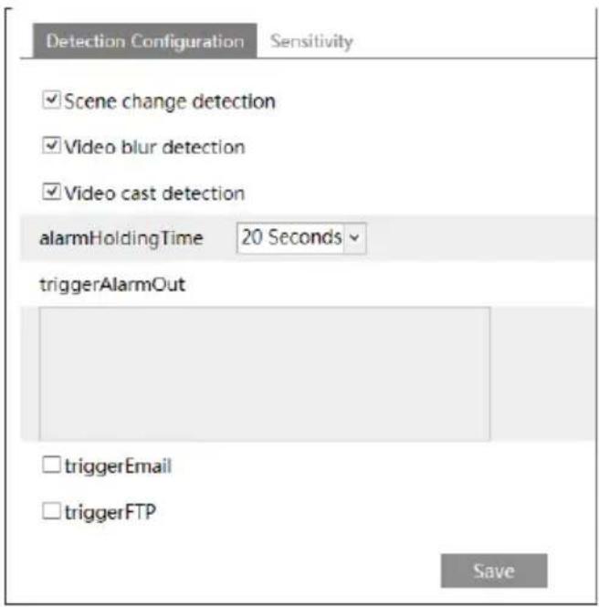
Detection Configuration Sensitivity ✓Scene change detection ✓Video blur detection ✓Video cast detection alarmHoldingTime 20 Seconds triggerAlarmOut ✓triggerEmail ✓triggerFTP Save-
Enable the relevant detection as required.
-
Scene Change Detection: The relevant alarms will be triggered if the scene of the monitor video has changed.
-
Video Blur Detection: The relevant alarms will be triggered if the monitor video is blurry.
• Video Cast Detection: The relevant alarms will be triggered if color cast happens to the monitor video. -
Set the alarm holding time and alarm trigger options. The setting steps are the same with that of motion detection. Please refer to motion detection chapter for details.
-
Click "Save" button to save the settings.
-
Set the sensitivity of the exception detection. Click "Sensitivity" tab to go to the interface as shown below.

flowchart
graph LR
    A["Detection Configuration"] --> B["Sensitivity"]
    B --> C["28"]
    C --> D["Save"]
Drag the slider to set the sensitivity value or directly input the sensitivity value in the textbox. Click "Save" button to save the settings.
The sensitivity value of Scene Change Detection: The higher the value is, the more sensitive the system responds to the amplitude of the scene change.
The sensitivity value of Video Blur Detection: The higher the value is, the more sensitive the system responds to the defocus of the device image. You should just the value according to the real situation.
The sensitivity value of Video Cast Detection: The higher the value is, the more sensitive the system responds to the color cast of the device image. You should also consider other factors.
※ Application Scenario Illustration
- Auto-focusing function should not been enabled for exception detection.
- Try not to enable object removal detection when light changes greatly in the scene.
- Please contact us for more detailed application scenarios.
6.4.3 Line Crossing
Line Crossing: The relevant alarms will be triggered if someone or something crosses the pre-defined alarm lines.
Go to Config→Event→Line Crossing interface as shown below.

text_image
Detection Config Area and Sensitivity Schedule Enable Alarm Alarm Holding Time 20 Seconds Trigger Alarm Out Trigger Email Trigger FTP Save-
Enable line crossing alarm and set the alarm holding time.
-
Set alarm trigger options. The setting steps are the same with that of motion detection. Please refer to motion detection chapter for details.
- Click "Save" button to save the settings.
- Set area and sensitivity of the line crossing alarm. Click "Area and Sensitivity" tab to go to the interface as shown below.

text_image
Detection Config Area and Sensitivity Schedule Cordon 1 Direction A<-B Draw Clear SaveSet the cordon number and direction. You can add 4 cordons at most.
Direction: A<->B, A->B and A<-B optional. It is the crossing direction of the intruder who crosses over the alarm line.
A<->B: The alarm will be triggered when the intruder crosses over the alarm line from B to A or from A to B.
A->B: The alarm will be triggered when the intruder crosses over the alarm line from A to B.
A<-B: The alarm will be triggered when the intruder crosses over the alarm line from B to A. Click "Draw" button and then drag the mouse to draw a cordon in the image on the left side. Click "Stop" button to stop drawing. Click "Clear" button to delete the cordons. Click "Save" button to save the settings.
- Set the schedule of the line crossing alarm. The setting steps of the schedule are the same with that of motion detection. Please refer to motion detection chapter for details.
※ Application Scenario Illustration
- Auto-focusing function should not been enabled for line crossing detection. If enabled, the video image will change so greatly that the algorithm will stop working temporarily.
- Try not to enable line crossing detection when light changes greatly in the scene.
- Try to install the camera at a certain angle of depression.
- Adequate light and clear scenery are very important to line crossing detection.
- Adjust the camera to make the detection area in the center of the video image. Make sure no obstructions are in the main crossing area. It is strongly recommended to make the obstructions (like trees, bushes, flags, etc.) outside the detection area.
- Please contact us for more detailed application scenarios.
Here we take some improper application scenarios for instance.
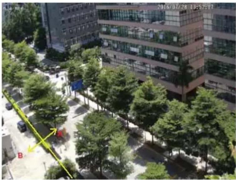
text_image
2016/07/28 13:52:17 BThere are so many trees near the road and cars running on the road, which make the scene too complex to detect the crossing objects.
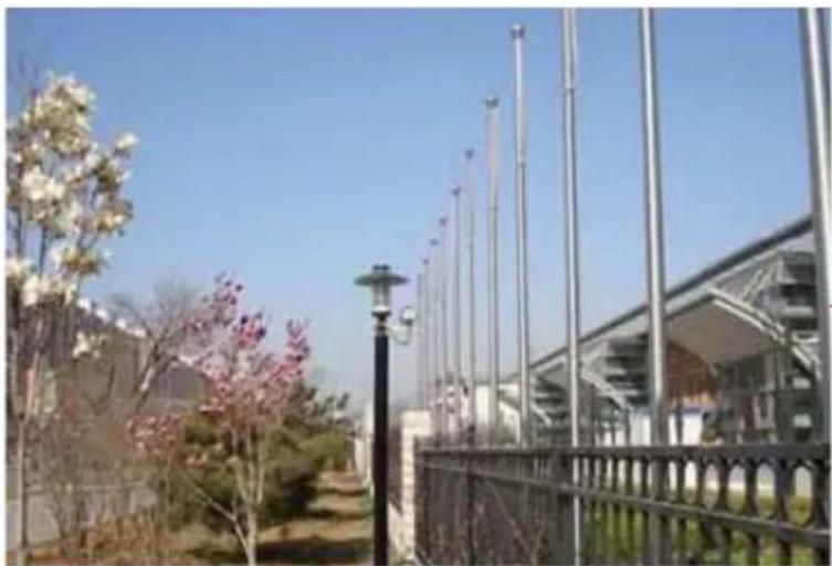
natural_image
Exterior view of a modern building with flagpoles and blooming pink flowers in the foreground (no signage)The ground is covered with vegetation; at the right of the fence is a gym where people pass by frequently. The above mentioned environment is too complex to detect the crossing objects.
6.4.4 Intrusion
Intrusion: The relevant alarms will be triggered if someone or something intrudes into the alarm areas or moves in the pre-defined alarm areas.
Go to Config→Event→Intrusion interface as shown below.

text_image
Detection Config Area Schedule Enable region intrusion detection Alarm Holding Time 20 Seconds Trigger Alarm Out Trigger Email Trigger FTP Save- Enable region intrusion detection alarm and set the alarm holding time.
- Set alarm trigger options. The setting steps are the same with that of motion detection. Please refer to motion detection chapter for details.
- Click "Save" button to save the settings.
- Set the alarm area of the intrusion detection. Click "Area" tab to go to the interface as shown below.
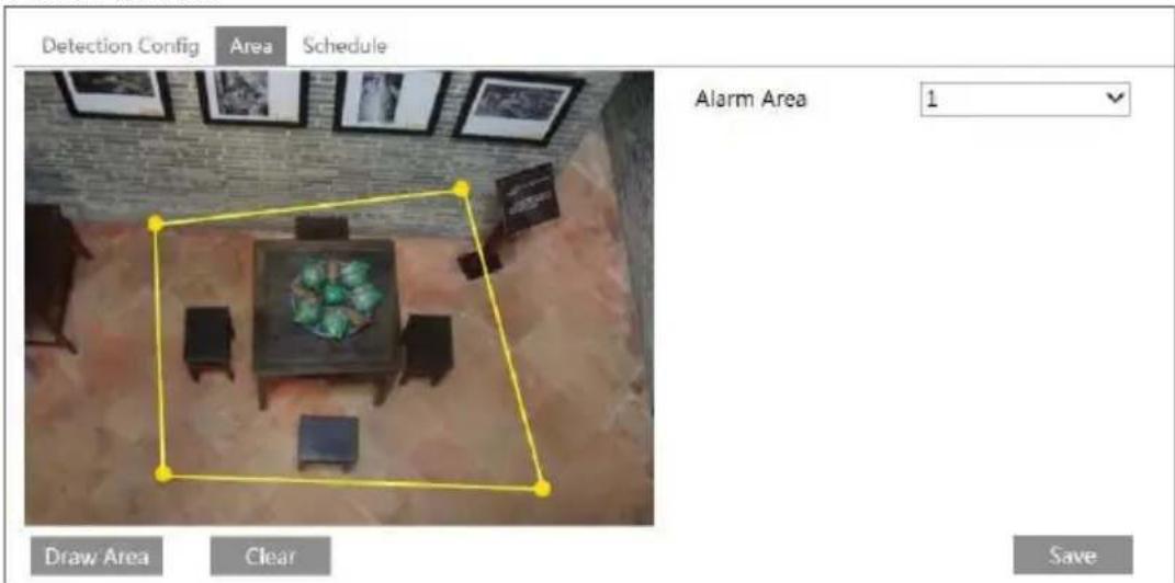
text_image
Detection Config Area Schedule Alarm Area 1 Draw Area Clear Save- Set the alarm area number on the right side. You can add 4 alarm areas at most.
- Click "Draw Area" button and then click around the area where you want to set as the alarm area in the image on the left side (the alarm area should be a closed area). Click "Stop Draw" button to stop drawing. Click "Clear" button to delete the alarm area. Click "Save" button to save the settings.
- Set the schedule of the intrusion detection. The setting steps of the schedule are the same with that of motion detection. Please refer to motion detection chapter for details.
※ Application Scenario Illustration
- Auto-focusing function should not been enabled for intrusion detection. If enabled, the
video image will change so greatly that the algorithm will stop working temporarily.
- Try not to enable intrusion detection when light changes greatly in the scene.
- Try to install the camera at a certain angle of depression.
- Adequate light and clear scenery are very important to intrusion detection.
- Adjust the camera to make the detection area in the center of the video image. The detected object should be in the detection area for about two seconds at least. Make sure no obstructions are in the main crossing area. It is strongly recommended to make the obstructions (like trees, bushes, flags, etc.) outside the detection area.
- Please contact us for more detailed application scenarios.
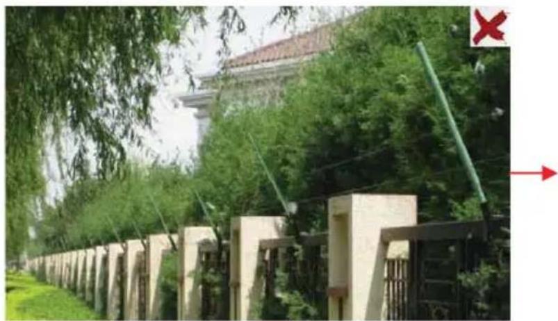
Here we take some improper application scenarios for instance.
natural_image
Exterior view of a traditional-style building with tiled roof and stone gate, surrounded by trees and greenery (no signage)The camera's angle of depression is not wide enough; there are so many trees in the scene. The above mentioned environment is too complex to detect the intrusion.

natural_image
Exterior view of a concrete fence with utility poles and trees along the road, no visible text or symbolsThe camera's angle of depression is not wide enough; the street lamps at night lead to light interference; the swaying trees in a windy day lead to random interference. All the above mentioned factors make the scene improper for intrusion detection.
6.5 Network Configuration
6.5.1 TCP/IP
Go to Config→Network→TCP/IP interface as shown below. There are two ways for network connection.
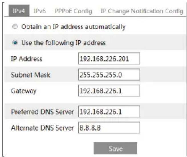
text_image
IPv4 IPv6 PPPoE Config IP Change Notification Config Obtain an IP address automatically Use the following IP address IP Address 192.168.226.201 Subnet Mask 255.255.255.0 Gateway 192.168.226.1 Preferred DNS Server 192.168.226.1 Alternate DNS Server 8.8.8.8 SaveUse IP address (take IPv4 for example)-There are two options for IP setup: obtain an IP address automatically by DHCP protocol and use the following IP address. Please choose one of the options for your requirements.
Use PPPoE-Click "PPPoE Config" tab to go to the interface as shown below. Enable PPPoE and then enter the user name and password from your ISP.
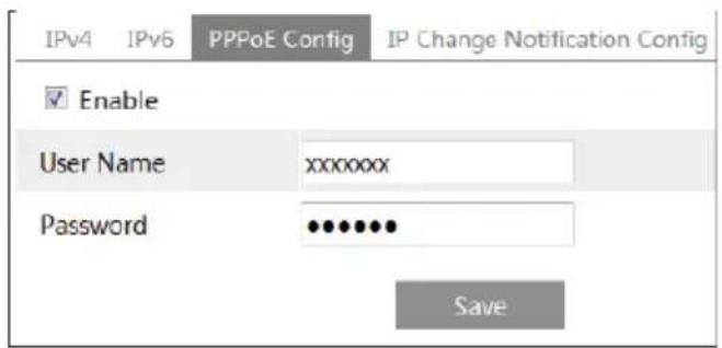
text_image
IPv4 IPv6 PPPoE Config IP Change Notification Config Enable User Name xxxxxxxx Password •••••••• SaveYou can choose either way of the network connection. If you use PPPoE to connect internet, you will get a dynamic WAN IP address. This IP address will change frequently. You may use the function of IP change notification.
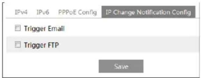
Click "IP Change Notification Config" to go to the interface as shown below.
text_image
IPv4 IPv6 PPPoE Config IP Change Notification Config Trigger Email Trigger FTP SaveTrigger Email: when the IP address of the device is changed, a new IP address will be sent to the appointed mailbox automatically
Trigger FTP: when the IP address of the device is changed, a new IP address will be sent to FTP server.
6.5.2 Port
Go to Config→Network→Port interface as shown below. HTTP port, Data port and RTSP port can be set.

text_image
Port Server DDNS SNMP RTSP UPnP Email FTP HTTP Port 80 Data Port 9008 RTSP Port 554 SaveHTTP Port: The default HTTP port is 80. It can be changed to any port which is not occupied.
Data Port: The default data port is 9008. Please change it as required.
RTSP Port: The default port is 554. Please change it as required.
6.5.3 Server Configuration
This function is mainly used for connecting network video management system.

text_image
Port Server DDNS SNMP RTSP UPnP Email FTP Enable Server Port 10 Server Address Device ID 1 Save-
Check "Enable".
-
Check the IP address and port of the transfer media server in the ECMS/NVMS. Then enable the auto report in the ECMS/NVMS when adding a new device. Next, input the remaining information of the device in the ECMS/NVMS. After that, the system will auto allot a device ID. Please check it in the ECMS/NVMS.
-
Input the above-mentioned server address, server port and device ID in the responding boxes. Click "Save" button to save the settings.
6.5.4 DDNS
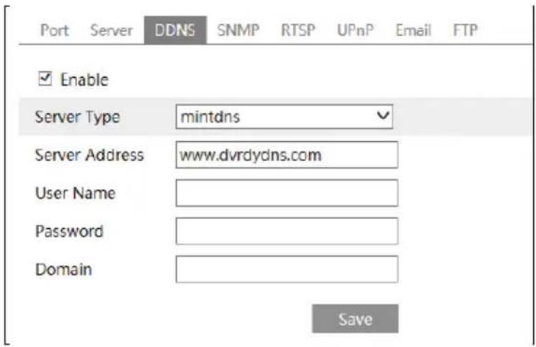
If your camera is set to use PPPoE as its default network connection, DDNS should be set for network access. Before you set the DDNS, please make sure you have registered a domain name on the DDNS server.
- Go to Config → Network→ DDNS.
text_image
Port Server DDNS SNMP RTSP UPnP Email FTP Enable Server Type mintdns Server Address www.dvrdydns.com User Name Password Domain Save- Apply for a domain name. Take www.dvrdyndns.com for example.
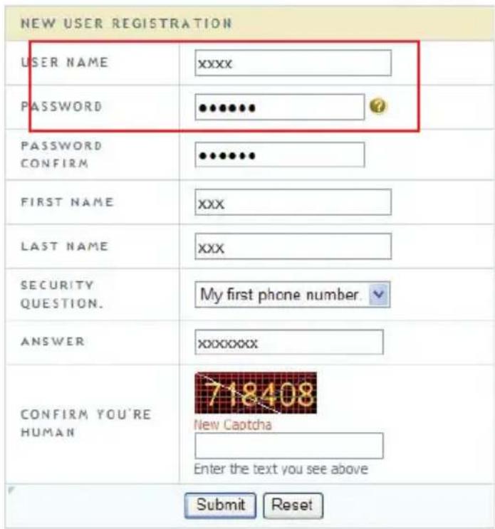
- Input www.dvrdydns.com in the IE address bar to visit its website. Then click "Registration" button.
text_image
NEW USER REGISTRATION USER NAME xxxx PASSWORD ●●●●●● PASSWORD CONFIRM ●●●●●● FIRST NAME xxx LAST NAME xxx SECURITY QUESTION. ANSWER My first phone number. XXXXXXXXX CONFIRM YOU'RE HUMAN 718408 New Captcha Enter the text you see above Submit ResetCreate domain name.

text_image
You must create a domain name to continue. Domain name must start with (a-z, 0-9). Cannot end or start, but may contain a hyphen and is not case-sensitive. dvrdydns.com Request DomainAfter you successfully request your domain name, you will see your domain in the list.

text_image
Search by Domain Search Click a name to edit your domain settings. NAME STATUS DOMAIN 654321ABC 65432.labc.dvrdydns.com Last Update: Not yet updated IP Address: 210.21.229.138 Create additional documents.- Input the username, password, domain you apply for in the DDNS configuration interface.
- Click "Save" button to save the settings.
6.5.5 SNMP
To get camera status, parameters and alarm information and remotely manage the camera, you can set the SNMP function. Before using the SNMP, please download the SNMP software and set the parameters of the SNMP, such as SNMP port, trap address.
- Go to Config → Network→SNMP.

text_image
SNMP v1/v2 Enable SNMPv1 Enable SNMPv2 Read SNMP Community Write SNMP Community Trap Address Trap Port 0 Trap community SNMP v3 Enable SNMPv3 Read User Name Security Level auth, priv Authentication Algorithm MD5 SHA Authentication Password Private-key Algorithm DES AES Private-key Algorithm Write User Name Security Level auth, priv Authentication Algorithm MD5 SHA Authentication Password Private-key Algorithm DES AES Private-key Algorithm Other Settings SNMP Port 0- Check the corresponding version checkbox (Enable SNMPv1, Enable SNMPv2, Enable SNMPv3) according to the version of the SNMP software you download.
- Set the "Read SNMP Community", "Write SNMP Community", "Trap Address", "Trap Port" and so on. Please make sure the settings are the same as that of your SNMP software.
Note: Please use the different version in accordance with the security level you required. The higher the version is, the higher the level of the security is.
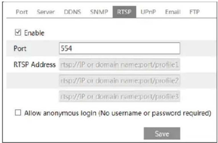
6.5.6 RTSP
Go to Config→Network→RTSP.
text_image
Port Server DDNS SNMP RTSP UPnP Email FTP ✓ Enable Port 554 RTSP Address rtsp://IP or domain name:port/profile1 rtsp://IP or domain name:port/profile2 rtsp://IP or domain name:port/profile3 □ Allow anonymous login (No username or password required) Save- Select "Enable".
- RTSP Port: Access port of the streaming media. The default number is 554.
- RTSP Address: The RTSP address you need to input in the media player.
- Check "Allow anonymous login...".
6.5.7 UPNP
If you enable this function, you can quickly access the camera via LAN and you don't need to configure the port mapping when the camera is connected to the WAN via the router. Go to Config→Network→UPnP. Enable UPNP and then input UPnP name.

text_image
Port Server DDNS SNMP RTSP UPnP Email FTP Enable UPnP Name SaveAfter you enable it and set the UPnP name, you will see the UPnP name by clicking "Network" on the desktop of your computer which is in the same local area network. Then double click this name to access the camera quickly.
6.5.8 Email
If you need to trigger Email when an alarm happens or IP address is changed, please set the Email here first.
Go to Config→Network→Email.
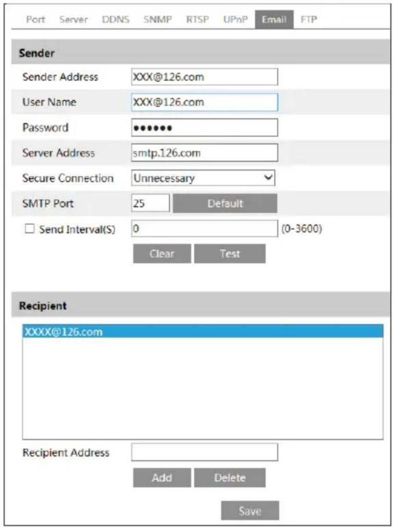
text_image
Port Server DDNS SNMP RTSP UPnP Email FTP Sender Sender Address XXX@126.com User Name XXX@126.com Password ••••••• Server Address smtp.126.com Secure Connection Unnecessary SMTP Port 25 Default Send Interval(S) 0 (0-3600) Clear Test Recipient XXXX@126.com Recipient Address Add Delete SaveSender Address: Sender's e-mail address.
User name and password: Sender's user name and password.
Server Address: The SMTP IP address or host name.
Select the secure connection type at the "Secure Connection" pull-down list according to actual needs.
SMTP Port: The SMTP port.
Send Interval(S): Set it as needed.
Click "Test" button to test the effectiveness of the account.
Recipient Address: Receiver's e-mail address.
6.5.9 FTP
After you set the FTP server, the captured pictures on an alarm will be uploaded to the FTP server.
Go to Config→Network→FTP.
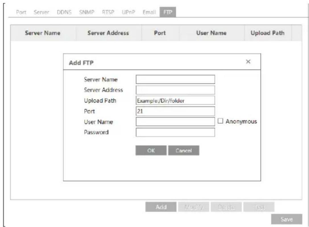
text_image
Port Server DDNS SNMP RTSP UPnP Email FTP Server Name Server Address Port User Name Upload Path Add FTP Server Name Server Address Upload Path Example:/Dir/folder Port 21 User Name Password Anonymous OK Cancel Add Modify Delete Test SaveTo Add FTP:
Server Name: The name of the FTP.
Server Address: The IP address or domain name of the FTP.
Upload Path: The path of uploading the files.
Port: The port of the FTP.
Use Name and Password: The username and password are used to login the FTP.
6.6 Security Configuration
6.6.1 User Configuration
Go to Config→Security→User interface as shown below.
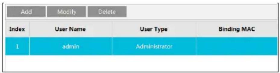
text_image
Add Modify Delete Index User Name User Type Binding MAC 1 admin AdministratorAdd user:
- Click "Add" button to pop up the following textbox.
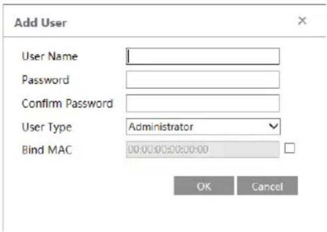
text_image
Add User User Name Password Confirm Password User Type Administrator Bind MAC 00:00:00:00:00:00 OK Cancel- Input user name in "User Name" textbox.
- Input letters or numbers in "Password" and "Confirm Password" textbox.
- Choose the use type.
- Input the MAC address of the PC in "Bind MAC" textbox.
- After binding physical address to the IP-CAM, you can access the device on this PC only. If the MAC address was "00:00:00:00:00:00" which means it can be connected to any computers.
- Click "OK" button and then the new added user will display in the user list.
Modify user:
- Select the user you need to modify password and physical address in the user configuration list box.
- The "Edit user" dialog box pops up by clicking "Modify" button.
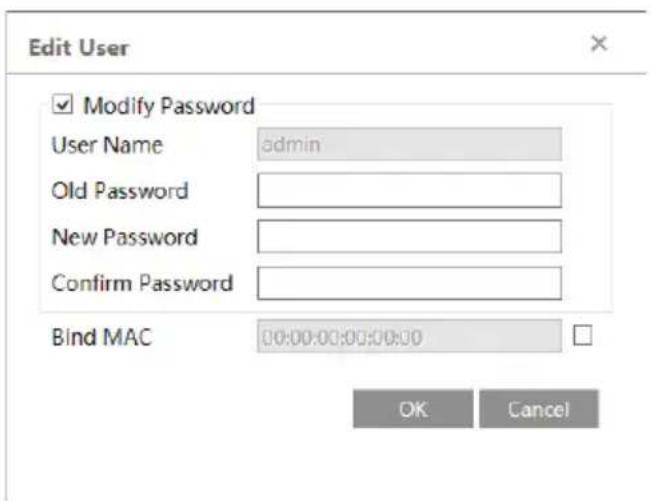
text_image
Edit User Modify Password User Name admin Old Password New Password Confirm Password Bind MAC 00:00:00:00:00:00 OK Cancel- Input old password of this user in the "Old Password" text box.
- Input new password in the "New password" and "Confirm Password" text box.
- Input computer's MAC address as required.
- Click "OK" button to save the settings.
Delete user:
- Select the user you want to delete in the user configuration list box.
- Click "Delete" button to delete the user.
Note: The default super administrator cannot be deleted.
6.6.2 Online User
Go to Config→Security→Online User. You can view the user who is viewing the live video.
6.6.3 Block and Allow Lists
Go to Config→Security→Block and Allow Lists interface as shown below.

text_image
IP Address Filter Settings Enable IP address filtering Block the following IP address Allow the following IP address Add Delete 0.0.0.0 Block the following MAC Address Enable MAC address filtering Block the following MAC address Allow the following MAC address Add Delete 00:00:00:00:00:00 SaveSetting steps are as follows:
Check "Enable IP address filtering" check box.
Select "Block the following IP address", input IP address in the IP address list box and click "Add" button. The operation step of "Allow the following IP address" and MAC address filter settings are the same with "Block the following IP address".
After you set the IP address or MAC address, the system will block or allow the user using the added IP address or MAC address to access the camera.
6.7 Maintenance Configuration
6.7.1 Backup and Restore
Go to Config→Maintenance→Backup & Restore.
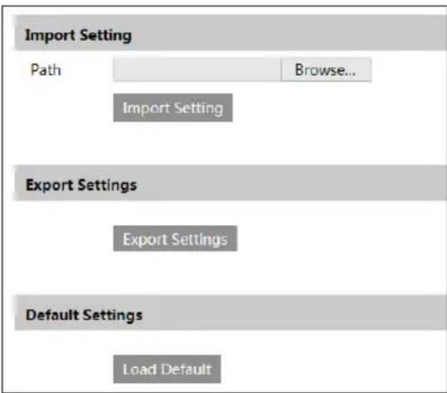
text_image
Import Setting Path Browse... Import Setting Export Settings Export Settings Default Settings Load Default- Import & Export Settings
You can import or export the setting information from PC or to device. Click "Browse" to select save path for import or export information on PC. Click "Import Setting" or "Export Setting" button.
- Default Settings
Click "Load Default" button to restore all system settings to default status.
6.7.2 Reboot
Go to Config→Maintenance→Reboot.
Click "Reboot" button to reboot the device.
Timed Reboot Setting:
Enable "Time Settings", set the date and time and then click "Save" button to save the settings.
6.7.3 Upgrade
Go to Config→Maintenance→Upgrade. In this interface, you can upgrade the system.

text_image
Upgrade System Path Browse Upgrade- Click "Browse" button to select the save path of the upgrade file
- Click "Upgrade" button to start upgrading the application program.
- The device will restart automatically
- After you successfully update the software, click "OK" button to close IE and then re-open IE to connect IP-Cam.
Caution! You can't disconnect to PC or close the IP-CAM during upgrade.
6.7.4 Operation Log
To query and export log:
- Go to Config → Maintenance→Operation Log.
| Main Type: All log Sub Type: All logStart Time: 2015-07-14 00:00:00 End Time: 2015-07-14 23:59:59 Search Export | |||||
| Index | Time | Main Type | Sub Type | User Name | Login IP |
| 1 | 2015-07-14 11:15:18 | Operation | Log In | admin | 192.168.12.53 |
| 2 | 2015-07-14 11:12:02 | Exception | Disconnected | 192.168.12.53 | |
| 3 | 2015-07-14 19:12:17 | Exception | Disconnected | 192.168.12.52 | |
- Select the main type, sub type, start and end time.
- Click "Search" to view the operation log.
- Click "Export" to export the operation log.
7 Record Search
Click Search to go to the interface as shown below. You can play the local video record. Before playing, please set the storage path of the video record in the local configuration interface and make sure there are record files.
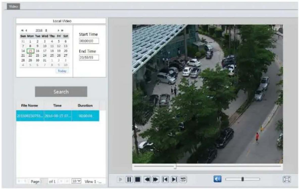
text_image
Local Video Sun Mon Tue Wed Thu Fri Sat 31 1 2 3 4 5 6 7 8 9 10 11 12 13 14 15 16 17 18 19 20 21 22 23 24 25 26 27 28 29 30 31 1 2 3 4 5 6 7 8 9 10 Today Start Time 00:00:00 End Time 21:59:59 Search File Name Time Duration 201608150753... 2016-08-15 07... 00:00:08 Page of 1 View 1 -...Choose the date and the start time and end time and then click "Search" button to search the record files. Double click the record file to play the record. The descriptions of the buttons on the playback interface are as follows.
| Icon Description Icon Description | |||
 | Play button. After pausing the video, click this button to continue playing. |  | Pause button. |
 | Stop button. Speed down. |  | |
 | Speed up. |  | Click it to play the previous record. |
 | Click it to play the next record. |  | Open/close watermark. |
  | Click it to enable / disable audio; drag the slider to adjust the volume after enabling audio. | Full screen. Click it to display full screen. Double click to exit full screen. | |
8 Appendix
Appendix 1 Q& A
Q: How to find my password if I forget it?
A: Reset the device to the default factory settings.
Default IP: 192.168.226.201; User name: admin; Password: 123456
Q : Fail to connect devices through IE browser, why?
A: Network is not well connected. Check the connection and make sure it is connected well.
B: IP is not available. Reset the valid IP.
C: Web port number has been revised: contact administrator to get the correct port number.
D: Exclude the above reasons. Recover default setting by IP-Tool.
Q : IP tool cannot search devices, why?
A: It may be caused by the anti-virus software in your computer. Please exit it and try to search device again.
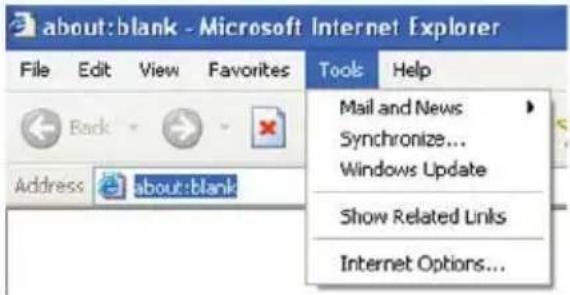
Q : IE cannot download ActiveX control. How can I do?
a. IE browser blocks ActiveX. Please do setup as below.
- Open IE browser. Click Tools----Internet Options....
text_image
about:blank - Microsoft Internet Explorer File Edit View Favorites Tools Help Back Address about:blank Mail and News Synchronize... Windows Update Show Related Links Internet Options...- Select Security----Custom Level....
- Enable all the sub options under "ActiveX controls and plug-ins".
- Then click OK to finish setup.
b. Other plug-ins or anti-virus blocks ActiveX. Please uninstall or close them.
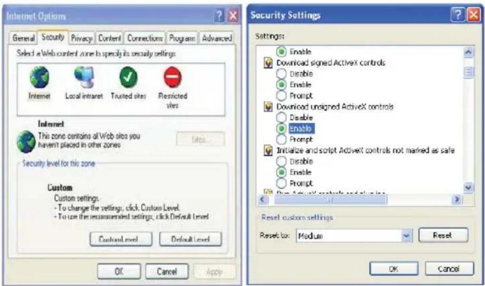
text_image
Internet Options General Security Privacy Content Connections Program Advanced Select a Web content zone to specify its security settings Internet Local intraret Trusted sites Restricted sites Internet This zone contains all Web sites you haven't placed in other zones Security level for this zone Custom Custom settings: To change the settings, click Custom Level. To use the recommended settings, click Default Level Custom Level Default Level OK Cancel Apply Security Settings Settings: Enable Download signed Activex controls Disable Enable Prompt Download unsigned Activex controls Disable Enable Prompt Initialize and script Activex controls not marked as safe Disable Enable Prompt Reset custom settings Reset to: Medium Reset OK CancelQ: No sound can be heard, why?
A: Audio input device is not connected. Please connect and try again.
B: Audio function is not enabled at the corresponding channel. Please enable this function.
9 Dimensions

text_image
4.25" (108 mm)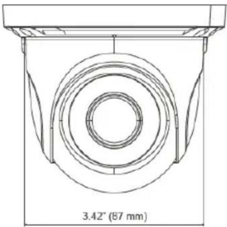
text_image
3.42" (87 mm)10 Warranty Information
Digital Watchdog (referred to as "the Warrantor") warrants the Camera against defects in materials or workmanships as follows:
Labor: For the initial five (5) years from the date of original purchase if the camera is determined to be defective, the Warrantor will repair or replace the unit with new or refurbished product at its option, at no charge.
Parts: In addition, the Warrantor will supply replacement parts for the initial five (5) years.
To obtain warranty or out of warranty service, please contact a technical support representative at 1+ (866) 446-3595, Monday through Friday from 9:00AM to 8:00PM EST.
A purchase receipt or other proof of the date of the original purchase is required before warranty service is rendered. This warranty only covers failures due to defects in materials and workmanship which arise during normal use. This warranty does not cover damages which occurs in shipment or failures which are caused by products not supplied by the Warrantor or failures which result from accident, misuse, abuse, neglect, mishandling, misapplication, alteration, modification, faulty installation, set-up adjustments, improper antenna, inadequate signal pickup, maladjustments of consumer controls, improper operation, power line surge, improper voltage supply, lightning damage, rental use of the product or service by anyone other than an authorized repair facility or damage that is attributable to acts of God.
11 Limits and Exclusions
There are no express warranties except as listed above. The Warrantor will not be liable for incidental or consequential damages (including, without limitation, damage to recording media) resulting from the use of these products, or arising out of any breach of the warranty. All express and implied warranties, including the warranties of merchantability and fitness for particular purpose, are limited to the applicable warranty period set forth above.
Some states do not allow the exclusion or limitation of incidental or consequential damages or limitations on how long an implied warranty lasts, so the above exclusions or limitations may not apply to you. This warranty gives you specific legal rights, and you may also have other rights from vary from state to state.
If the problem is not handled to your satisfaction, then write to the following address:
Digital Watchdog, Inc.
ATTN: RMA Department
5436 W Crenshaw St
Tampa, FL 33634
Service calls which do not involve defective materials or workmanship as determined by the Warrantor, in its sole discretion, are not covered. Cost of such service calls are the responsibility of the purchaser.

text_image
DWDIGITAL WATCHDOG™
Complete Surveillance Solutions
Headquarters Office: 5436 W Crenshaw St, Tampa, FL 33634 Sales Office: 16220 Bloomfield Ave., Cerritos, California, USA 90703
PH: 866-446-3595 | FAX: 813-888-9262
www.Digital-Watchdog.com
technicalsupport@dwcc.tv
Technical Support PH:
USA & Canada 1+ (866) 446-3595
International 1+ (813) 888-9555
French Canadian 1+ (514) 360-1309
Technical Support Hours: Monday-Friday
9:00am to 8:00pm Eastern Standard Time