RVM5160DHCC - Microwaves HOTPOINT - Free user manual and instructions
Find the device manual for free RVM5160DHCC HOTPOINT in PDF.

User questions about RVM5160DHCC HOTPOINT
0 question about this device. Answer the ones you know or ask your own.
Ask a new question about this device
Download the instructions for your Microwaves in PDF format for free! Find your manual RVM5160DHCC - HOTPOINT and take your electronic device back in hand. On this page are published all the documents necessary for the use of your device. RVM5160DHCC by HOTPOINT.
USER MANUAL RVM5160DHCC HOTPOINT
Installation Instructions
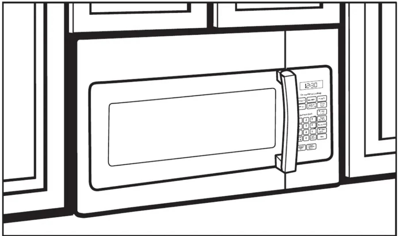
Over the Range Microwave Oven
AVM4160, JNM3161, JVM3160, and RVM5160
Questions? Call 800.GE.CARES (800.432.2737) or Visit our Website at: GEAppliances.com
BEFORE YOU BEGIN
Read these instructions completely and carefully.
• IMPORTANT — Save these instructions for local inspector's use.
• IMPORTANT — Observe all governing codes and ordinances.
- Note to Installer – Be sure to leave these instructions with the consumer.
- Note to Consumer – Keep these instructions for future reference.
- Skill level – Installation of this appliance requires basic mechanical and electrical skills.
- Proper installation is the responsibility of the installer.
- Product failure due to improper installation is not covered under the warranty.
text_image
12:30 Can be added to cooking Place 1 Place 2 Place 3 Place 4 Place 5 Place 6 Place 7 Place 8 Place 9 Place 10 Place 11 Place 12 Place 13 Place 14 Place 15 Place 16 Place 17 Place 18 Place 19 Place 20 Place 21 Place 22 Place 23 Place 24 Place 25 Place 26 Place 27 Place 28 Place 29 Place 30 Place 31 Place 32 Place 33 Place 34 Place 35 Place 36 Place 37 Place 38 Place 39 Place 40 Place 41 Place 42 Place 43 Place 44 Place 45 Place 46 Place 47 Place 48 Place 49 Place 50 Place 51 Place 52 Place 53 Place 54 Place 55 Place 56 Place 57 Place 58 Place 59 Place 60 Place 61 Place 62 Place 63 Place 64 Place 65 Place 66 Place 67 Place 68 Place 69 Place 70 Place 71 Place 72 Place 73 Place 74 Place 75 Place 76 Place 77 Place 78 Place 79 Place 80 Place 81 Place 82 Place 83 Place 84 Place 85 Place 86 Place 87 Place 88 Place 89 Place 90 Place 91 Place 92 Place 93 Place 94 Place 95 Place 96 Place 97 Place 98 Place 99 Place 100Throughout this manual, features and appearance may vary from your model.
CONTENTS
General information
Important Safety Instructions .... 3
Electrical Requirements 3
Tools You Will Need 4
Hood Exhaust 5,6
Damage – Shipment/Installation .... 7
Parts Included 7
Mounting Space 8
Step-by-step installation guide
Placement of Mounting Plate 9-11
Removing the Mounting Plate 9
Finding the Wall Studs 9
Determining Mounting Plate Location .....10
Aligning the Mounting Plate 11
Installation Types 12-23
A Recirculating.... 13-16
Attach Mounting Plate to Wall ...... 13
Preparation of Top Cabinet 13
Adjust the Blower.... 14
Installing the Charcoal Filter...... 15
Mount the Microwave Oven .....15, 16
Installing the Charcoal Filter
without Top Access.... 16
B Outside Top Exhaust.... 17-20
Attach Mounting Plate to Wall .....17
Preparation of Top Cabinet ....18
Adjust Blower Motor....18
Assemble and Install Adaptor .....19
Mount the Microwave Oven .....19, 20
Connecting Ductwork......20
Outside Back Exhaust 21-24
Installation Overview.... 21
Preparing Rear Wall for
Outside Back Exhaust ....21
Attach Mounting Plate to Wall .....21, 22
Preparation of Top Cabinet ......22
Adapting Blower for Outside
Back Exhaust 22, 23
Mount the Microwave Oven ..... 23, 24
Before You Use Your Microwave Oven 25
IMPORTANT SAFETY INSTRUCTIONS
A qualified electrician must perform a ground continuity check on the wall receptacle before beginning the installation to ensure that the outlet box is properly grounded. If not properly grounded, or if the wall receptacle does not meet electrical requirements noted (under ELECTRICAL REQUIREMENTS), a qualified electrician should be employed to correct any deficiencies.
natural_image
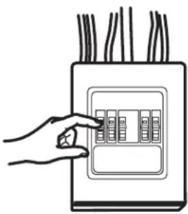
Hand placing a button into an electrical outlet panel (no text or symbols visible)WARNING
Risk of Electric Shock. Can cause injury or death: Remove house fuse or open circuit breaker before beginning installation to avoid severe or fatal shock injury.
WARNING
Risk of Electric Shock.
Can cause injury or death: THIS APPLIANCE MUST BE PROPERLY GROUNDED to avoid severe or fatal shock.

text_image
Ensure proper ground exists before use.120 V Models
The power cord of this appliance is equipped with a three-prong (grounding) plug which mates with a standard three-prong (grounding) wall receptacle to minimize the possibility of electric shock hazard from this appliance.
Where a standard two-prong wall receptacle is encountered, it must be replaced with a properly grounded three-prong wall receptacle, installed by a qualified electrician.
WARNING
Risk of Electric Shock.
Can cause injury or death: DO NOT, under any circumstances, cut, deform or remove any of the prongs from the power cord. Do not use with an extension cord. Failure to comply may cause fire.
CAUTION
For personal safety, the mounting surface must be
capable of supporting the cabinet load, in addition to the added weight of this 63–85 pound product, plus additional microwave oven loads of up to 50 pounds or a total weight of 113–135 pounds.
CAUTION
For personal safety, this product cannot be installed in cabinet
arrangements such as an island or a peninsula. It must be mounted to BOTH a top cabinet AND a back wall.
CAUTION
To avoid the risk of personal injury (back injury or other
injuries due to excessive weight of the microwave) or property damage, you will need two people to install this microwave.
ELECTRICAL REQUIREMENTS
120 V Models
This product requires a three-prong grounded outlet. Product rating is 120 volts AC, 60 Hertz, 15 amps, and 1.70 kilowatts. This product must be connected to a supply circuit of the proper voltage and frequency. Wire size must conform to the requirements of the National Electrical Code or the prevailing local code for this kilowatt rating. The power supply cord and plug should be brought to a separate 15 to 20 ampere branch circuit single grounded outlet. The outlet box should be located in the cabinet above the microwave oven and away from any potential microwave ducting. The outlet box and supply circuit should be installed by a qualified electrician and conform to the National Electrical Code or the prevailing local code.
TOOLS YOU WILL NEED

1 and #2
Phillips
screwdriver
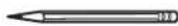
Pencil
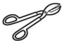
Tin snips (for cutting damper, if required)
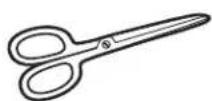
Scissors (to cut template, if necessary)

Gloves

natural_image
Illustration of a motor, a cylindrical component, and a curved tool (no text or symbols)Saw (saber, hole or keyhole)

Safety goggles

Level
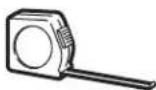

Ruler or tape measure and straight edge

Carpenter square (optional)
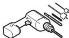
Electric drill with 316 ", 716 ", 12 " and 58 " drill bits

Stud
finder
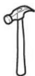
Hammer (optional)
Filler blocks or scrap wood pieces, if needed for top cabinet spacing (used on recessed bottom cabinet installations only)
Duct and masking tape
HOOD EXHAUST
NOTE: Read these next two pages only if you plan to vent your exhaust to the outside. If you plan to recirculate the air back into the room, proceed to page 6. Below are examples of Outside Top Exhaust and Outside Back Exhaust duct system layouts. Note the position of the microwave oven relative to the duct system.
OUTSIDE TOP EXHAUST (EXAMPLE ONLY)
The following chart describes an example of one possible ductwork installation.
 | DUCT PIECES | LENGTH x USED = | EQUIVALENT NUMBER LENGTH | |
| Roof Cap | 24 Ft. x (1) = | 24 Ft. | ||
| 12 Ft. Straight Duct (6" Round) | 12 Ft. x (1) = | 12 Ft. | ||
| Rectangular-to-Round Adaptor* | 5 Ft. x (1) = | 5 Ft. | ||
| Equivalent lengths of duct pieces are based on actual tests and reflect requirements for good venting performance with any vent hood. Total Length = | 41 Ft. | |||
| DUCT PIECES | LENGTH x USED = | EQUIVALENT NUMBER LENGTH | ||
| Roof Cap | 24 Ft. x (1) = | 24 Ft. | ||
| 12 Ft. Straight Duct (6" Round) | 12 Ft. x (1) = | 12 Ft. | ||
| Rectangular-to-Round Adaptor* | 5 Ft. x (1) = | 5 Ft. | ||
| Equivalent lengths of duct pieces are based on actual tests and reflect requirements for good venting performance with any vent hood.Total Length = | 41 Ft. | |||
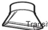
*IMPORTANT: If a rectangular-to-round transition adaptor is used, the bottom corners of the damper will have to be cut to fit, using the tin snips, in order to allow free movement of the damper.
| OUTSIDE BACK EXHAUST (EXAMPLE ONLY)The following chart describes an example of one possibleductwork installation. | |||
 | DUCT PIECES LENGTH* x USED = LENGTH | EQUIVALENT NUMBER | |
| Wall Cap | 40 Ft. x (1) = 40 Ft. | ||
| 3 Ft. Straight Duct(31⁄4" x 10" Rectangular) | 3 Ft. x (1) = 3 Ft. | ||
| 90° Elbow | 10 Ft. x (2) = 20 Ft. | ||
| Equivalent lengths of duct pieces are based on actual tests andreflect requirements for good venting performance with any vent hood.Total Length = | 63 Ft. | ||
| DUCT PIECES LENGTH* x USED | = LENGTH | EQUIVALENT | |
| Wall Cap | 40 Ft. x (1) = | 40 Ft. | |
| 3 Ft. Straight Duct ( 314'' × 10'' Rectangular ) | 3 Ft. x (1) = | 3 Ft. | |
| 90° Elbow | 10 Ft. x (2) = | 20 Ft. | |
| Equivalent lengths of duct pieces are based on actual tests and reflect requirements for good venting performance with any vent hood.Total Length = | 63 Ft. | ||
NOTE: For back exhaust, care should be taken to align exhaust with space between studs, or wall should be prepared at the time it is constructed by leaving enough space between the wall studs to accommodate exhaust.
NOTE: If you need to install ducts, note that the total duct length of 3 14 " x 10" rectangular or 6" diameter round duct should not exceed 140 equivalent feet. Outside ventilation requires a HOOD EXHAUST DUCT. Read the following carefully:
NOTE: It is important that venting be installed using the most direct route and with as few elbows as possible.
This ensures clear venting of exhaust and helps prevent blockages. Also, make sure dampers swing freely and nothing is blocking the ducts.
Exhaust connection:
The hood exhaust has been designed to mate with a standard 314 " x 10" rectangular duct.
If a round duct is required, a rectangular-to-round transition adaptor must be used. Do not use less than a 6" diameter duct.
Maximum duct length:
For satisfactory air movement, the total duct length of 314 " x 10" rectangular or 6" diameter round duct should not exceed 140 equivalent feet.
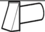
Elbows, transitions, wall and roof caps, etc.,
Present additional resistance to airflow and are equivalent to a section of straight duct which is longer than their actual physical size. When calculating the total duct length, add the equivalent lengths of all transitions and adaptors plus the length of all straight duct sections. The chart below shows you how to calculate total equivalent ductwork length using the approximate feet of equivalent length of some typical duct pieces.
| DUCT PIECES LENGTH x USED = | EQUIVALENT NUMBER EQUIVALENT LENGTH | ||
 | Rectangular-to-Round on Adaptor* | 5 Ft. x ( ) = | Ft. |
 | Wall Cap | 40 Ft. x ( ) = | Ft. |
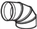 | 90° Elbow | 10 Ft. x ( ) = | Ft. |
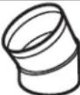 | 45° Elbow | 5 Ft. x ( ) = | Ft. |
 | 90° Elbow | 25 Ft. x ( ) = | Ft. |
 | 45° Elbow | 5 Ft. x ( ) = | Ft. |
 | Roof Cap | 24 Ft. x ( ) = | Ft. |
| Straight Duct 6" Round or 1⁄4"3x 10" Rectangular | 1 Ft. x ( ) = | Ft. | |
| Total Ductwork | = Ft. | ||

* IMPORTANT: If a rectangular-to-round transition adaptor is used, the bottom corners of the damper will have to be cut to fit, using the tin snips, in order to allow free movement of the damper.
Equivalent lengths of duct pieces are based on actual tests and reflect requirements for good venting performance with any vent hood.
DAMAGE – SHIPMENT/ INSTALLATION
- If the unit is damaged in shipment, return the unit to the store in which it was bought for repair or replacement.
- If the unit is damaged by the customer, repair or replacement is the responsibility of the customer.
- If the unit is damaged by the installer (if other than the customer), repair or replacement must be made by arrangement between customer and installer.
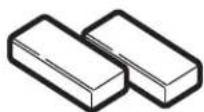
PARTS INCLUDED
HARDWARE PACKET
| PART | QUANTITY | |
 | Wood Screws (3/16" x 2") | 2 |
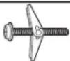 | Toggle Bolts (and wing nuts) (1/4" x 3") | 4 |
 | Self-aligning Machine Screw (1/4"-28 x 3-1/4") | 3 |
 | Nylon Grommet (for metal cabinets) | 2 |
 | Power Cord Strap (plastic) | 1 |
You will find the installation hardware contained in a packet with the unit. Check to make sure you have all these parts.
NOTE: Some extra parts are included.
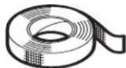
PARTS INCLUDED
ADDITIONAL PARTS
| PART | QUANTITY | |
 | Top Cabinet Template | 1 |
 | Rear Wall Template | 1 |
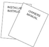 | Installation Instructions and Owners Manual | 11 |
 | Grease Filters | 2 |
 | Exhaust Adaptor | 1 |
 | Tray 1 | |
 | Turntable Ring | 1 |
 | Charcoal Filter (on some models) | 1* |
* NOTE:
- For JVM3160 and AVM4160, filter is in accessory pack.
It is not installed in the product. - For JNM3161, filter is already installed in the product.
- For RVM5160, filter not included.
MOUNTING SPACE

text_image
13" max* 16-½" 30" 30" min. Bottom edge of cabinet needs to be 30" or more from the cooking surface Backsplash 2" 66" or more from the floor to the top of the microwave ovenNOTES:
- The space between the cabinets must be 30" wide and free of obstructions.
- This microwave oven is for installation over ranges up to 36" wide.
- If you are going to vent your microwave oven to the outside, see Hood Exhaust Section for exhaust duct preparation.
- When installing the microwave oven beneath smooth, flat cabinets, be careful to follow the instructions on the top cabinet template for power cord clearance.
- For models setup in Recirc Exhaust: Do not allow cabinetry or other objects to block the airflow of the vent.
- The product should not be installed over any cooktop or range with a combined BTU greater than 60,000 BTU.
* 13" max: for standard installation, 15" cabinet depth requires additional steps using an additional installation kit JX15BUMPWW/BB.
Installation Instructions
1 PLACEMENT OF THE MOUNTING PLATE
A REMOVING THE MICROWAVE OVEN FROM THE CARTON/ REMOVING THE MOUNTING PLATE
1 Open the box and fold back all four carton flaps fully against the carton sides. Remove the following items from the protective foam: installation instructions, filters, exhaust adaptor, damper, and the small hardware bag. Do not remove the foam protecting the front of the microwave oven.
2 Then carefully roll the microwave oven and carton over onto the top side. The microwave oven should be resting in the foam.
Carton
Foam
3Pull the carton up and off the microwave oven.
4The mounting plate is attached to the back of the microwave oven. Remove the two screws holding it to the microwave oven. The plate will be used as the rear wall template and for mounting the microwave oven to the wall.
5Set the microwave oven upright. Remove and properly discard plastic bags and foam.
6 Open the microwave oven door and remove the plastic sheet and tape from inside the microwave oven door. Remove the tape covering the turntable hub.
B FINDING THE WALL STUDS
Wall Studs
Center
1 Find the studs, using one of the following methods:
A. Stud finder.
OR
B. Use a hammer to tap lightly across the mounting surface to find a solid sound. This will indicate a stud location.
2 After locating the stud(s), find the center by probing
the wall with a small nail to find the edges of the stud. Then place a mark halfway between the edges.
3 The center of any adjacent studs should be 16" or 24" from this mark.
Draw a line down the center of the studs.
IMPORTANT: The microwave must be connected to at least one wall stud.
C DETERMINING MOUNTING PLATE LOCATION UNDER YOUR CABINET
Plate Position – flat bottom cabinet
text_image
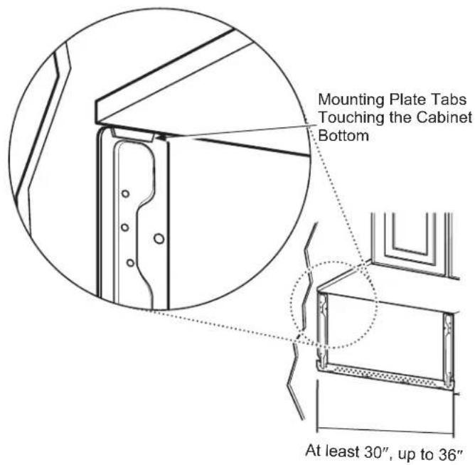
Mounting Plate Tabs Touching the Cabinet Bottom At least 30", up to 36"Plate Position – recessed cabinet bottom

text_image
Mounting Plate Tabs Touching the Back Frame of the Cabinet 30" to CooktopPlate Position – cabinet with front overhang
text_image
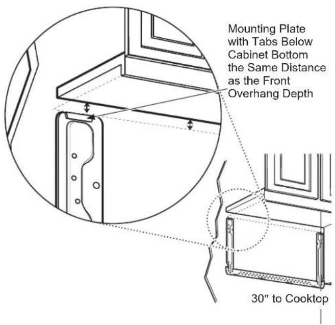
Mounting Plate with Tabs Below Cabinet Bottom the Same Distance as the Front Overhang Depth 30" to CooktopYour cabinets may have decorative trim that interferes with the microwave oven installation. You may need to remove the decorative trim to install the microwave oven properly and to make it level.
Use a level to make sure the cabinet bottom is level.
If the cabinets have a front overhang, install the mounting plate down the same distance as the front overhang depth. This will keep the microwave oven level.
Measure the inside depth of the front overhang.
2 Draw a horizontal line on the back wall an equal distance below the cabinet bottom as the inside depth of the front overhang.
3 for this type of installation with front overhang, align the mounting tabs with this horizontal line, not touching the cabinet bottom as described in Step D.
D ALIGNING THE MOUNTING PLATE
text_image
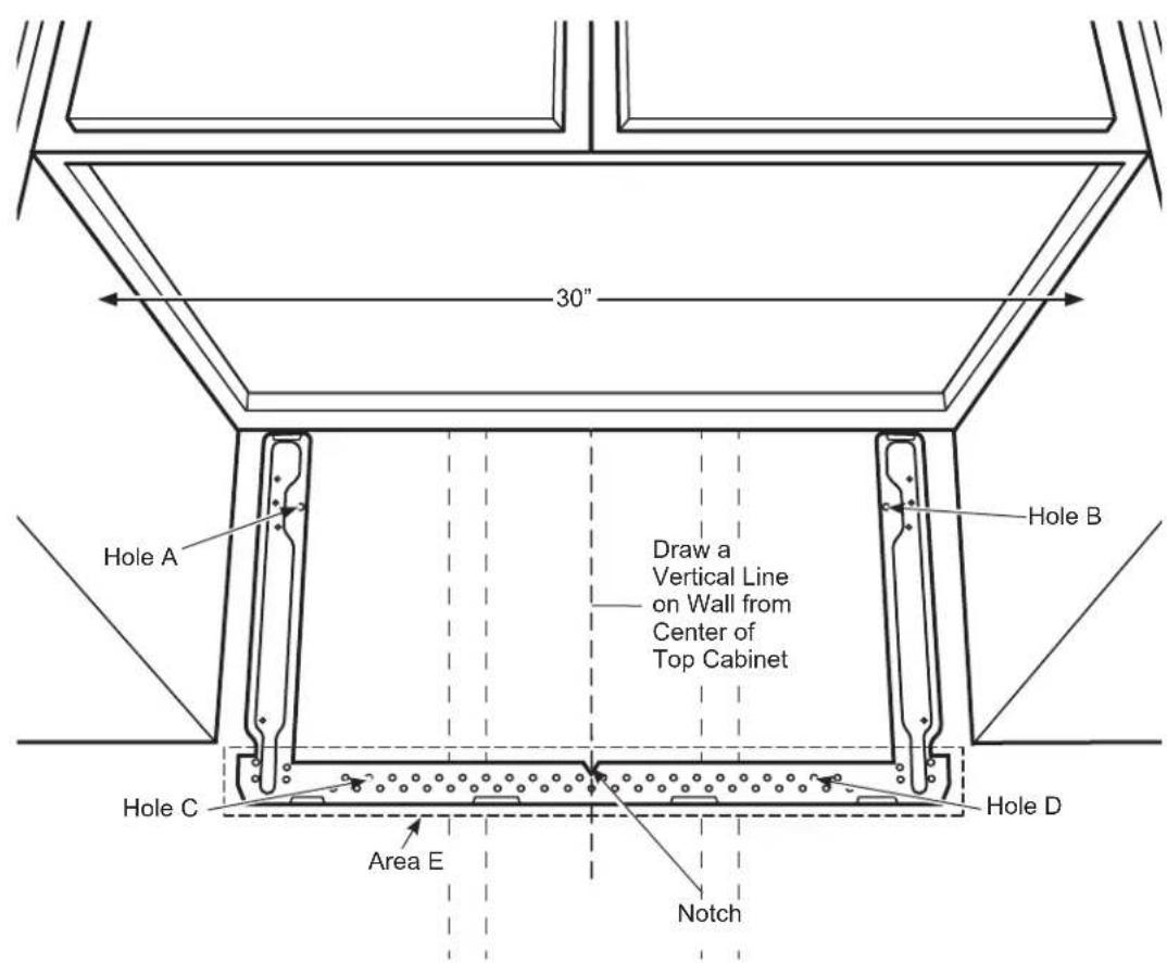
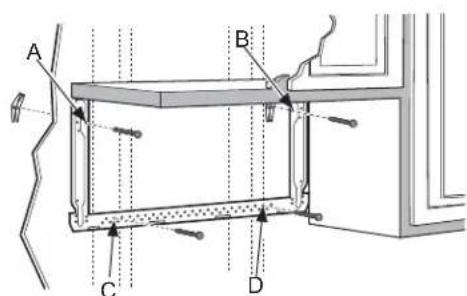
30" Hole A Draw a Vertical Line on Wall from Center of Top Cabinet Hole B Hole C Area E Notch Hole DCAUTION
Wear gloves to avoid cutting edges.
1 Draw a vertical line on the wall at the center of the 30" wide space.
2 Use the mounting plate as the template for the rear wall. Place the mounting plate on the wall, making sure that the tabs are touching the bottom of the cabinet or the level line drawn in Step C for cabinets with front overhang. Line up the notch and center line on the mounting plate to the center line on the wall.
3 While holding the mounting plate with one hand, draw circles on the wall at holes A, B, C, and D (see illustration above/actual plate marked with arrows). Four holes must be used for mounting.
NOTE: Holes C and D are inside area E. If neither C nor D is in a stud, find a stud somewhere in area E and draw a fifth circle to line up with the stud. It is important to use at least one wood screw mounted firmly in a stud to support the weight of the microwave oven.
Set the mounting plate aside.
WARNING
Risk of electric shock. Can cause
injury or death. Take care to not drill into electrical wiring inside walls or cabinets.
4 Drill holes on the circles. If there is a stud, drill a 316 " hole for wood screws. For holes that don't line up with a stud, drill a 58 " hole for toggle bolts.
NOTE: DO NOT MOUNT THE PLATE AT THIS TIME.
2 INSTALLATION TYPES (Choose A, B or C)
This microwave oven is designed for adaptation to the following 3 types of ventilation:
A. Recirculating (Non-Vented Ductless)
B. Outside Top Exhaust (Vertical Duct)
C. Outside Back Exhaust (Horizontal Duct)
NOTE: Select the type of ventilation required for your installation and proceed to that section.
A RECIRCULATING (NON-VENTED DUCTLESS)

natural_image
Line drawing of a microwave oven with two arrows indicating airflow or movement (no text or symbols on the device itself)A Charcoal Filter Accessory Kit is required for the non-vented exhaust. (See your Owner's Manual for the kit number.)
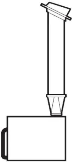
B OUTSIDE TOP EXHAUST (VERTICAL DUCT)
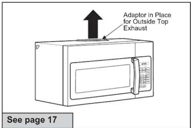
text_image
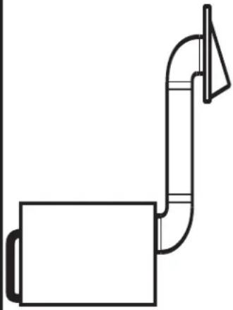
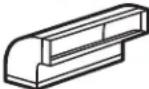
Adaptor in Place for Outside Top Exhaust See page 17C OUTSIDE BACK EXHAUST (HORIZONTAL DUCT)

natural_image
Line drawing of a microwave oven with a paper lid and front panel, no text or symbols present
RECIRCULATING (Non-Vented Ductless)
INSTALLATION OVERVIEW
A1. Attach Mounting Plate to Wall
A2. Prepare Top Cabinet
A3. Install Charcoal Filter (Supplied with AVM4160 and JVM3160 models)
A4. Mount the microwave oven
A5. Installing/Replacing the Charcoal Filter Without Access to Top Screws and the Unit Has Already Been Mounted.
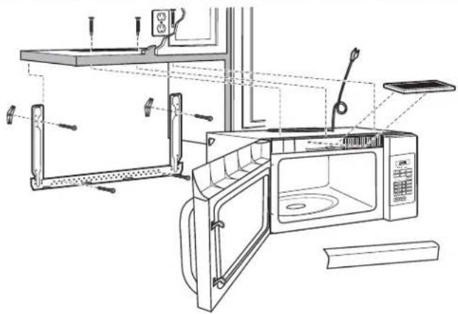
natural_image
Line drawing of a microwave oven with open door, shelves, and control panel (no text or symbols)
ATTACH THE MOUNTING PLATE TO THE WALL
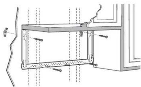
natural_image
Technical line drawing of a structural frame with mounting holes and bolts (no text or symbols)Attach the plate to the wall using toggle bolts. At least one wood screw must be used to attach the plate to a wall stud.
1 Remove the toggle wings from the bolts.
2 Insert the bolts into the mounting plate through the holes designated to go into drywall and reattach the toggle wings to 34 " onto each bolt.
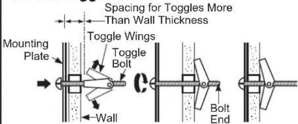
To use toggle bolts:

text_image
Spacing for Toggles More Than Wall Thickness Toggle Wings Mounting Plate Toggle Bolt Wall Bolt End3 Place the mounting plate against the wall and insert the toggle wings into the holes in the wall to mount the plate.
NOTE: Before tightening toggle bolts and wood screw, make sure the tabs on the mounting plate touch the bottom of the cabinet or the horizontal level line when pushed flush against the wall and that the plate is properly centered under the cabinet.
CAUTION
Be careful to avoid pinching
fingers between the back of the mounting plate and the wall.
4 Tighten all bolts. Pull the plate away from the wall to help tighten the bolts.

USE TOP CABINET TEMPLATE FOR PREPARATION OF TOP CABINET
You need to drill holes for the top support screws and a hole large enough for the power cord to fit through.
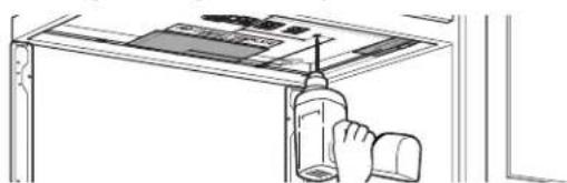
natural_image
Line drawing of a hand holding a bottle and cap, partially enclosed in a window frame (no text or symbols)- Read the instructions on the TOP CABINET TEMPLATE.
- Tape it underneath the top cabinet.
- Drill the holes, following the instructions on the TOP CABINET TEMPLATE.
CAUTION
Wear safety goggles when
drilling holes in the cabinet bottom.
A3 ADJUST BLOWER MOTOR
1 Remove the screws holding the blower unit and the screws securing the blower plate. Remove the blower plate from the outer case by sliding it toward the back of the microwave and pulling up.
Blower Motor Screws
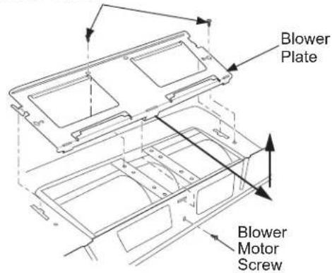
text_image
Blower Plate Blower Motor Screw2 Carefully pull out the blower unit. The wires will extend far enough to allow you to adjust the blower unit.
text_image
Fan Blades Wires Back of Microwave3 Roll the blower 90° so that fan blade openings are facing toward the front of the microwave.
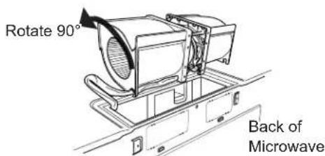
text_image
Rotate 90° Back of MicrowaveNote: Make sure the wires remain routed through the openings in the motor frame. To avoid damage to the fan motor wiring, insert motor carefully such that the fan motor wiring does not contact the microwave power cord bracket.
WARNING
Risk of Electric Shock.
Can cause injury or death. Do not pull or stretch the blower unit wiring. Make sure the wires are not pinched.
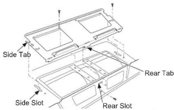
4\$lide the blower plate back onto the microwave by placing the side tabs into the slots and pushing gently until the back tab is seated into the rear slot. Replace 3 screws.

text_image
Side Tab Rear Tab Side Slot Rear SlotA4 INSTALLING THE CHARCOAL FILTER
1 Remove 2 screws on top of microwave oven, just above the grille panel, using a Phillips screwdriver. If two screws are not accessible, see section A5.
2 Open the door.
3 Remove the grille.

text_image
Grille4 Insert the top of the filter up and into the grooves on both sides of the inside of the top opening. Once you have cleared the bottom tab, push the bottom of the filter in until it rests in place behind the tab.

text_image
Grooves in Microwave for Filter on Each Side Filter (dashed to show details of groves) Bottom Tab5 Replace the grille by inserting the top grill flange into the slots in the case as shown.

text_image
Grille Grille Ensure bottom tabs are seated as shown.6 Replace the 2 top screws.
7 Close the door.
natural_image
Illustration of two people interacting near a table with a computer (no text or symbols visible)⚠️CAUTION risk of personal injury (back injury or other injuries due
to excessive weight of the microwave) or property damage, you will need two people to uninstall this microwave.
IMPORTANT: Do not grip or use handle during removal.
⚠ WARNING Risk of Electric Shock. Can cause injury or death: If removing unit
with metal countertops, cover the edge of the power supply cord hole with the power supply cord (nylon grommet).
IMPORTANT: If filler blocks are not used, case damage may occur from overtightening screws.
NOTE: When mounting the microwave, thread power cord through hole in bottom of top cabinet. Keep it tight throughout Steps 1–3. Do not pinch cord or lift microwave oven by pulling cord.
1 Lift microwave, tilt it forward, and hook slots at back bottom edge onto four lower tabs of mounting plate.
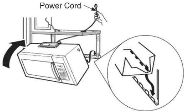
text_image
Power Cord2 Rotate front of microwave oven up against cabinet bottom.
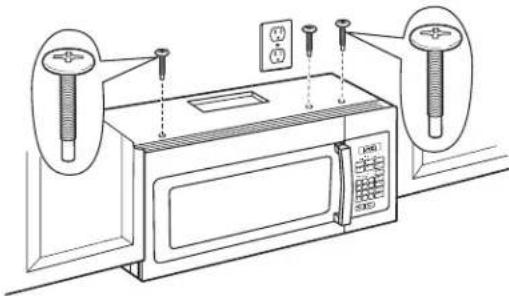
3 Insert 3 self-aligning screws ( 14 "-28 x 2 14 ") through outer top cabinet holes. Turn two full turns on each screw.
Cabinet Front
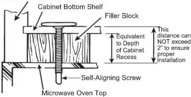
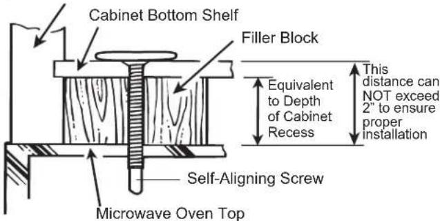
text_image
Cabinet Bottom Shelf Filler Block Equivalent to Depth of Cabinet Recess This distance can NOT exceed 2" to ensure proper installation Self-Aligning Screw Microwave Oven TopSelf-Aligning Screws
text_image
Diagram of a microwave oven setup with labeled components and wiring connections4 Tighten the three screws to the top of the microwave oven. (While tightening screws, hold the microwave oven in place against the wall and the top cabinet.)
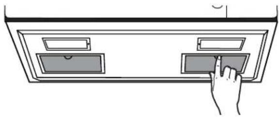
5 Install grease filters. See the Owner's Manual packed with the microwave oven.
natural_image
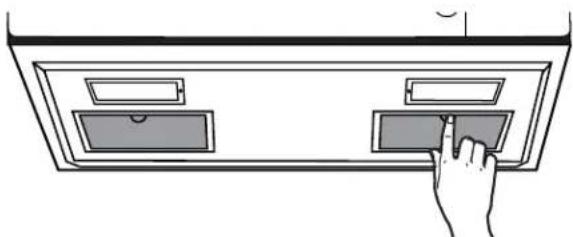
Hand inserting a tray into a cabinet (no text or symbols visible)A6 INSTALLING/REPLACING THE CHARCOAL FILTER WITHOUT ACCESS TO TOP SCREWS AND THE UNIT HAS ALREADY BEEN MOUNTED

CAUTION
To avoid the risk of personal injury
(back injury or other injuries due to excessive weight of the microwave) or property damage, you will need two people to uninstall this microwave.
IMPORTANT: Do not grip or use handle during removal.
WARNING
Risk of Electric Shock. Can cause
injury or death: If removing unit with metal countertops, cover the edge of the power supply cord hole with the power supply cord (nylon grommet).
IMPORTANT: If filler blocks are not used, case damage may occur from overtightening screws.
1 Loosen the 3 screws on the top of the microwave oven (inside the cabinet).
natural_image
Line drawing of a microwave oven with two wall-mounted sensors and control knobs (no text or symbols)2 Lift microwave, tilt it forward and unhook slots at back bottom edge from the four lower tabs of the mounting plate.
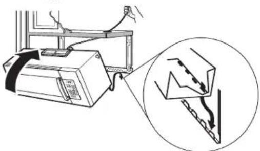
natural_image
Diagram showing a computer setup with an attached device and a magnified view of its internal components (no text or symbols present)3 Replace the filter using instructions from section A4.
4Reinstall unit following instructions from A5.
B OUTSIDE TOP EXHAUST (Vertical Duct)
INSTALLATION OVERVIEW
B1. Attach Mounting Plate to Wall
B2. Prepare Top Cabinet
B3. Adjust Blower Motor
B4. Install Exhaust Adaptor
B5. Mount Microwave Oven
B6. Connect Ductwork
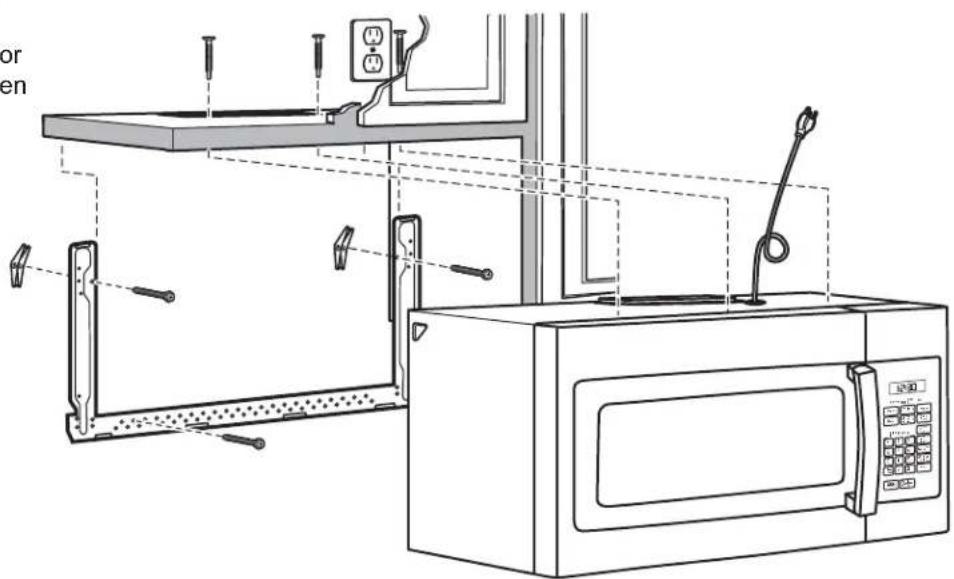
text_image
Technical diagram of a microwave oven with labeled components and wiring connectionsB1 ATTACH THE MOUNTING PLATE TO THE WALL
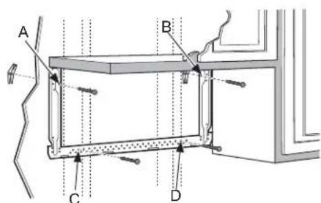
text_image
A B C DAttach the plate to the wall using toggle bolts. At least one wood screw must be used to attach the plate to
a wall stud. Recommended locations on the mounting plate are indicated by A, B, C and D.
1 Remove the toggle wings from the bolts.
2 Insert the bolts into the mounting plate through the holes designated to go into drywall and reattach the toggle wings to 34 " onto each bolt.
To use toggle bolts:
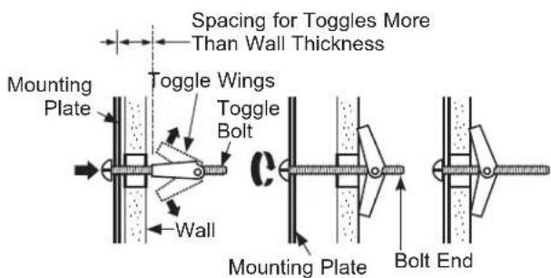
text_image
Spacing for Toggles More Than Wall Thickness Mounting Plate Toggle Wings Toggle Bolt Wall Mounting Plate Bolt End3 Insert the toggle wings into the holes in the wall and place the mounting plate against the wall.
NOTE: Before tightening toggle bolts and wood screw, make sure the tabs on the mounting plate touch the bottom of the cabinet when pushed flush against the wall and that the plate is properly centered under the cabinet.
CAUTION
Be careful to avoid pinching
fingers between the back of the mounting plate and the wall.
4 Tighten all bolts. Pull the plate away from the wall to help tighten the bolts.
B2 USE TOP CABINET TEMPLATE FOR PREPARATION OF TOP CABINET
You need to drill holes for the top support screws, a hole large enough for the power cord to fit through, and a cutout large enough for the exhaust adaptor.

natural_image
Line drawing of a hand using a tool to clean or install a cabinet (no text or symbols visible)- Read the instructions on the TOP CABINET TEMPLATE.
- Tape it underneath the top cabinet.
- Drill the holes, following the instructions on the TOP CABINET TEMPLATE.
CAUTION
Wear safety goggles when the cabinet bottom.
B3 ADJUST BLOWER MOTOR
1 Remove the screws holding the blower unit and the screws securing the blower plate. Remove the blower plate from the outer case by sliding it toward the back of the microwave and pulling up.
Blower Motor Screws

text_image
Blower Plate Blower Motor Screw2 Carefully pull out the blower unit. The wires will extend far enough to allow you to adjust the blower unit.
text_image
Rotate 90° Back of Microwave3 Roll the blower so that fan blade openings are facing the top of the oven. Place the blower back into the opening.
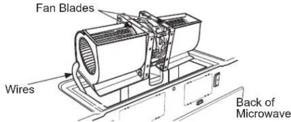
text_image
Fan Blades Wires Back of MicrowaveNote: Make sure the wires remain routed through the openings in the motor frame. To avoid damage to the fan motor wiring, insert motor carefully such that the fan motor wiring does not contact the microwave power cord bracket.
⚠ WARNING
Risk of Electric Shock.
Can cause injury or death. Do not pull or stretch the blower unit wiring. Make sure the wires are not pinched.
4\$lide the blower plate back onto the microwave by placing the side tabs into the slots and pushing gently until the back tab is seated into the rear slot. Replace 3 screws.
text_image
Side Tab Rear Tab Side Slot Rear SlotB4 ASSEMBLE AND INSTALL ADAPTOR
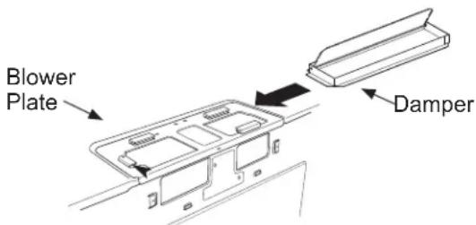
text_image
Blower Plate Damper1 Place the microwave oven in its upright position, with the top of the unit facing up and the front of the unit facing toward you.
2 Remove the screw on the back side of the blower plate and raise the blower plate off of the microwave.
3 Slide the damper from left to right into the tabs on the blower plate. The yellow tape on the damper should be facing away from you.
Remove the yellow tape from the damper. Make sure that the damper pivots easily before mounting microwave oven.
4 You will need to make adjustments to assure proper alignment with your house exhaust duct after the microwave oven is installed.
5 Position the blower plate with damper back on the microwave and secure it with the screws that were removed.
natural_image
Illustration of two people interacting near a table or board (no text or symbols visible)CAUTION
To avoid the risk of personal
injury (back injury or other injuries due to excessive weight of the microwave) or property damage, you will need two people to install this microwave.
IMPORTANT: Do not grip or use handle during installation.
WARNING
Risk of Electric Shock. Can
cause injury or death: If installing unit with metal countertops, cover the edge of the power supply cord hole with the power supply cord bushing.
IMPORTANT: If filler blocks are not used, case damage may occur from overtightening screws.
NOTE: When mounting the microwave, thread power cord through hole in bottom of top cabinet. Keep it tight throughout Steps 1–3. Do not pinch cord or lift microwave oven by pulling cord.
1 Lift microwave, tilt it forward, and hook slots at back bottom edge onto four lower tabs of mounting plate.

text_image
Power CordRotate front of microwave oven up against cabinet bottom.
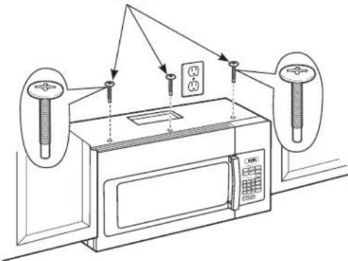
3 Insert a self-aligning screw through top-center cabinet hole. Temporarily secure the microwave oven by turning the screw at least two full turns after the threads have engaged. (It will be completely tightened later.) Insert 2 self-aligning screws (1/4"-28 x 2 1/4") through outer top cabinet holes. Turn two full turns on each screw.
natural_image
Line drawing of a microwave oven with two wall-mounted sensors and a control panel (no text or symbols)Cabinet Front
text_image
Cabinet Bottom Shelf Filler Block Equivalent to Depth of Cabinet Recess This distance can NOT exceed 2" to ensure proper installation Self-Aligning Screw Microwave Oven Top4 Tighten the three screws to the top of the microwave oven. (While tightening screws, hold the microwave oven in place against the wall and the top cabinet.)
5 Install grease filters. See the Owner's Manual packed with the microwave oven.
natural_image
Hand inserting a card into a cabinet (no text or symbols visible)B6 CONNECTING DUCTWORK

text_image
House Duct1 Extend the house duct down to connect to the exhaust adaptor.
2 Seal exhaust duct joints using duct tape.

OUTSIDE BACK EXHAUST (Horizontal Duct)
INSTALLATION OVERVIEW
C1. Prepare Rear Wall
C2. Attach Mounting Plate to Wall
C3. Prepare Top Cabinet
C4. Adjust Blower
C5. Mount the Microwave Oven
text_image
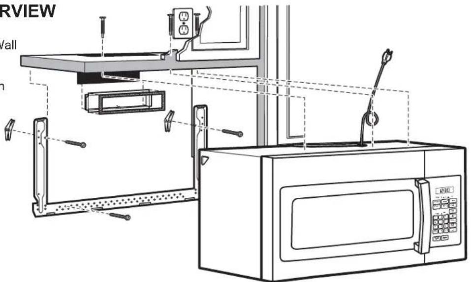
RVIEW /all h
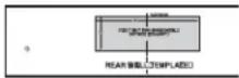
PREPARING THE REAR WALL FOR OUTSIDE BACK EXHAUST
You need to cut an opening in the rear wall for outside exhaust.

text_image
REAR WALL TEMPLATE 300- Read the instructions on the REAR WALL TEMPLATE.
- Tape it to the rear wall, lining up with the holes previously drilled for holes A and B in the mounting plate.
- Cut the opening, following the instructions of the REAR WALL TEMPLATE.

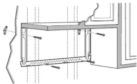
ATTACH THE MOUNTING PLATE TO THE WALL

natural_image
Technical line drawing of a cabinet or enclosure with mounting brackets and structural supports (no text or symbols)Attach the plate to the wall using toggle bolts. At least one wood screw must be used to attach the plate to a wall stud.
1 Remove the toggle wings from the bolts.
2 Insert the bolts into the mounting plate through the holes designated to go into drywall and reattach the toggle wings to 34 " onto each bolt.
C2 ATTACH THE MOUNTING PLATE TO THE WALL (cont.)
To use toggle bolts:
text_image
Spacing for Toggles More Than Wall Thickness Mounting Plate Toggle Wings Toggle Bolt Wall Bolt End3 Place the mounting plate against the wall and insert the toggle wings into the holes in the wall to mount the plate.
NOTE: Before tightening toggle bolts and wood screw, make sure the tabs on the mounting plate touch the bottom of the cabinet when pushed flush against the wall and that the plate is properly centered under the cabinet.
CAUTION
Be careful to avoid pinching
fingers between the back of the mounting plate and the wall.
4 Tighten all bolts. Pull the plate away from the wall to help tighten the bolts.
C3 USE TOP CABINET TEMPLATE FOR PREPARATION OF TOP CABINET
You need to drill holes for the top support screws and a hole large enough for the power cord to fit through.

natural_image
Line drawing of a hand inserting a component into a rack inside a cabinet (no text or symbols)- Read the instructions on the TOP CABINET TEMPLATE.
- Tape it underneath the top cabinet.
- Drill the holes, following the instructions on the TOP CABINET TEMPLATE.
CAUTION
Wear safety goggles when
drilling holes in the cabinet bottom.
C4 ADAPTING BLOWER FOR OUTSIDE BACK EXHAUST
1 Remove the blower motor screws that holds the blower plate to the microwave oven. Slide the plate toward the back of the microwave and lift up to remove.

text_image
Blower Motor Screws Blower Plate2 Remove screw on the back of the unit.

natural_image
Technical line drawing of a vehicle chassis frame with screw indicator (no text or symbols)3 Carefully remove fan from cavity. Remove the wire from the notch at the bottom of the fan after it is removed from the cavity.

natural_image
Technical line drawing of a mechanical device with no visible text or symbols4 The fan needs to be turned 180 degrees to the right to be in the correct orientation, keeping the blower part of the fan where the air comes out at the top of the fan. The wire needs to be reinsterted into the cage housing once it has been oriented correctly.
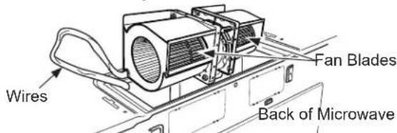
text_image
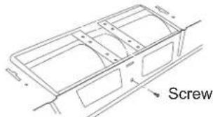
Wires Fan Blades Back of Microwave5 Remove the knockout plates in the back of the unit with snips. Knockout Plates:

text_image
Back of microwaveKnockout Plates: Snip all 4 webs on each knockout panel and remove the metal knockouts for rear airflow. Please take care to remove any sharp edges created from removing the knockout plates.
C4 ADAPTING BLOWER FOR OUTSIDE BACK EXHAUST (cont.)
6 Gently place the fan back into the cavity with the exhaust portion of the fan at the top and facing the back of the unit.

natural_image
Technical line drawing of a car interior frame with ventilation grilles (no text or symbols)Note: Make sure the wires remain routed through the openings in the motor frame. To avoid damage to the fan motor wiring, insert motor carefully such that the fan motor wiring does not contact the microwave power cord bracket.
7 Replace screw on the back of the unit.
text_image
Screw8 Slide the vent damper on back of the unit with the hinge at the top.
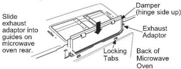
text_image
Slide exhaust adaptor into guides on microwave oven rear. Damper (hinge side up) Exhaust Adaptor Locking Tabs Back of Microwave Oven9 Replace the vent cover on the unit and secure it to the unit by replacing the two screws that were removed, with one in the middle hole and one on either side.
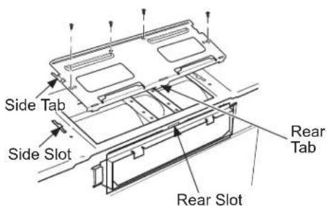
text_image
Side Tab Side Slot Rear Tab Rear Slotnatural_image
Illustration of two people interacting near a table with a lamp (no text or symbols visible)CAUTION
To avoid the risk of personal injury
(back injury or other injuries due to excessive weight of the microwave) or property damage, you will need two people to install this microwave.
IMPORTANT: Do not grip or use handle during installation.
WARNING
Risk of Electric Shock. Can cause
injury or death: If installing unit with metal countertops, cover the edge of the power supply cord hole with the power supply cord bushing.
IMPORTANT: If filler blocks are not used, case damage may occur from overtightening screws.
NOTE: When mounting the microwave, thread power cord through hole in bottom of top cabinet. Keep it tight throughout Steps 1–3. Do not pinch cord or lift microwave oven by pulling cord.
1 Lift microwave, tilt it forward, and hook slots at back bottom edge onto four lower tabs of mounting plate.

text_image
Power Cord2 Rotate front of microwave oven up against cabinet bottom.
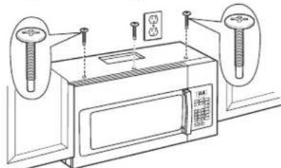
3 Insert a self-aligning screw through top-center cabinet hole. Temporarily secure the microwave oven by turning the screw at least two full turns after the threads have engaged. (It will be completely tightened later.) Insert 2 self-aligning screws (1/4"-28 x 2 1/4") through outer top cabinet holes. Turn two full turns on each screw.
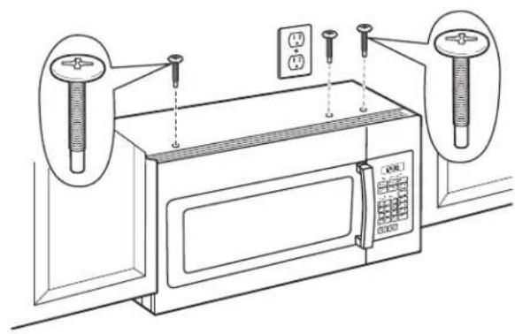
natural_image
Line drawing of a microwave oven with mounted sensors and electrical outlets (no text or symbols)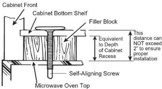
text_image
Cabinet Front Cabinet Bottom Shelf Filler Block Equivalent to Depth of Cabinet Recess This distance can NOT exceed 2" to ensure proper installation Self-Aligning Screw Microwave Oven Top4 Tighten the three screws to the top of the microwave oven. (While tightening screws, hold the microwave oven in place against the wall and the top cabinet.)
5 Install grease filters. See the Owner's Manual packed with the microwave oven.
natural_image
Hand inserting a card into a tray (no text or symbols visible)Make sure the microwave oven has been installed according to instructions.

text_image
INSTALLATION INSTRUCTIONS6 Read the Owner's Manual.

text_image
OWNER'S MANUAL2 Remove all packing material from the microwave oven.
3 Install turntable and turntable ring in cavity.
4 Replace house fuse or turn breaker back on.

natural_image
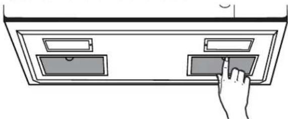
Illustration of a hand interacting with an electrical outlet panel (no text or symbols visible)7 KEEP INSTALLATION INSTRUCTIONS FOR THE LOCAL INSPECTOR'S USE.
text_image
INSTALLATION INSTRUCTIONS5 120 V Models: Plug power cord into a dedicated 15- to 20-amp electrical outlet.

text_image
Ensure proper ground exists before use.Where a standard two-prong wall receptacle is encountered, it is very important to have it replaced with a properly grounded three-prong wall receptacle, installed by a qualified electrician.
text_image
12:30 On Infection Cooking Water 1 Water 2 Water 3 Water 4 Water 5 Water 6 Water 7 Water 8 Water 9 Water 10 Water 11 Water 12 Water 13 Water 14 Water 15 Water 16 Water 17 Water 18 Water 19 Water 20 Water 21 Water 22 Water 23 Water 24 Water 25 Water 26 Water 27 Water 28 Water 29 Water 30 Water 31 Water 32 Water 33 Water 34 Water 35 Water 36 Water 37 Water 38 Water 39 Water 40 Water 41 Water 42 Water 43 Water 44 Water 45 Water 46 Water 47 Water 48 Water 49 Water 50 Water 51 Water 52 Water 53 Water 54 Water 55 Water 56 Water 57 Water 58 Water 59 Water 60 Water 61 Water 62 Water 63 Water 64 Water 65 Water 66 Water 67 Water 68 Water 69 Water 70 Water 71 Water 72 Water 73 Water 74 Water 75 Water 76 Water 77 Water 78 Water 79 Water 80 Water 81 Water 82 Water 83 Water 84 Water 85 Water 86 Water 87 Water 88 Water 89 Water 90 Water 91 Water 92 Water 93 Water 94 Water 95 Water 96 Water 97 Water 98 Water 99 Water100natural_image
Hand placing a panel into an electrical box with wires (no text or symbols visible)ADVERTENCIA
natural_image
Illustration of a motor, a cylindrical component, and a curved tool (no text or symbols)natural_image
Simple line drawing of a vertical cylindrical device mounted on a base, with no text or symbols present.natural_image
Simple line drawing of a battery connected to a curved pipe with an arrow (no text or symbols)natural_image
Line drawing of a microwave oven with open door, doors, and control panel (no text or labels)
ADHERA LA PLACA DE
MONTAJE A LA PARED
natural_image
Technical line drawing of a structural frame with bolted joints and dashed alignment lines (no text or symbols)natural_image
Line drawing of a hand using a tool to lift a component on a shelf (no text or symbols)natural_image
Simple line drawing of two people interacting near a table (no text or symbols)PRECAUCIÓN
text_image
Diagram of a microwave oven with labeled components and wiring connectionsnatural_image
Hand inserting a tray into a cabinet (no text or symbols visible)natural_image
Line drawing of a microwave oven setup with two sensors and control panels (no text or symbols)natural_image
Illustration of a printer with cable being connected to a rack, accompanied by a magnified inset showing a mechanical component (no text or symbols present)natural_image
Line drawing of a microwave oven with attached appliances and control panel (no text or symbols)B1 ADHIERA LA PLACA DE MONTAJE A LA PARED
text_image
A B C Dnatural_image
Line drawing of a hand inserting a component into a cabinet (no text or symbols)natural_image
Simple line drawing of two people interacting near a table (no text or symbols)PRECAUCIÓN
natural_image
Line drawing of a microwave oven with mounted sensors and control panel (no text or symbols)Frente del Gabinete

natural_image
Hand inserting a card into a cabinet panel (no text or symbols visible)natural_image
Line drawing of a microwave oven setup with control panel and wiring (no text or symbols)