EXT-HDRPT100M - Câble Wi-Fi KanexPro - Free user manual and instructions
Find the device manual for free EXT-HDRPT100M KanexPro in PDF.

User questions about EXT-HDRPT100M KanexPro
0 question about this device. Answer the ones you know or ask your own.
Ask a new question about this device
Download the instructions for your Câble Wi-Fi in PDF format for free! Find your manual EXT-HDRPT100M - KanexPro and take your electronic device back in hand. On this page are published all the documents necessary for the use of your device. EXT-HDRPT100M by KanexPro.
USER MANUAL EXT-HDRPT100M KanexPro
Read this user manual carefully before using this product. Pictures shown in this manual is for reference only, different model and specifications are subject to real product.
This manual is only for operation instruction only, not for any maintenance usage. The functions described in this version are updated till September 2016. In the constant effort to improve our product, we reserve the right to make functions or parameters changes without notice or obligation. Please refer to the dealers for the latest details.
All product function is valid till 2016-9-22.
Trademarks
Product model and logo are trademarks. Any other trademarks mentioned in this manual are acknowledged as the properties of the trademark owner. No part of this publication may be copied or reproduced without the prior written consent.
FCC Statement
This equipment generates, uses and can radiate radio frequency energy and, if not installed and used in accordance with the instructions, may cause harmful interference to radio communications. It has been tested and found to comply with the limits for a Class B digital device, pursuant to part 15 of the FCC Rules. These limits are designed to provide reasonable protection against harmful interference in a commercial installation.
Operation of this equipment in a residential area is likely to cause interference, in which case the user at their own expense will be required to take whatever measures may be necessary to correct the interference.
Any changes or modifications not expressly approved by the manufacture would void the user's authority to operate the equipment.


SAFETY PRECAUTIONS
To insure the best from the product, please read all instructions carefully before using the device. Save this manual for further reference.
- Unpack the equipment carefully and save the original box and packing material for possible future shipment
- Follow basic safety precautions to reduce the risk of fire, electrical shock and injury to persons.
- Do not dismantle the housing or modify the module. It may result in electrical shock or burn.
- Using supplies or parts not meeting the products' specifications may cause damage, deterioration or malfunction.
● Refer all servicing to qualified service personnel.
- To prevent fire or shock hazard, do not expose the unit to rain, moisture or install this product near water.
- Do not put any heavy items on the extension cable in case of extrusion.
- Do not remove the housing of the device as opening or removing housing may expose you to dangerous voltage or other hazards.
● Install the device in a place with fine ventilation to avoid damage caused by overheat.
- Keep the module away from liquids.
- Spillage into the housing may result in fire, electrical shock, or equipment damage. If an object or liquid falls or spills on to the housing, unplug the module immediately.
- Do not twist or pull by force ends of the optical cable. It can cause malfunction.
- Do not use liquid or aerosol cleaners to clean this unit. Always unplug the power to the device before cleaning.
● Unplug the power cord when left unused for a long period of time.
● Information on disposal for scrapped devices: do not burn or mix with general household waste, please treat them as normal electrical wastes.
Table of Contents
1. Introduction......1
1.1 Introduction to EXT-HDRPT100M....1
1.2 Features....1
1.3 Package Contents....2
2. Product Appearance....3
2.1 Front Panel....3
2.2 Rear Panel .... 3
3. System Connection ....5
3.1 Usage Precautions....5
3.2 System Diagram....5
3.3 Connection Procedure 5
3.4 Application....6
3.5 Twisted Pair Cable Connection ....7
4. Operation....8
4.1 Unit ID setup 8
4.2 RS232 Control....8
4.2.1 RS232 Command Format....8
4.2.2 Installation/uninstallation of RS232 Control Software 9
4.2.3 Basic Settings .... 10
4.3 EDID Management....11
4.4 HDCP Management....11
5. Specification 12
6. Panel Drawing....13
7. Troubleshooting & Maintenance....14
8. After-sales Service 15
9. Warranty ....16
1. Introduction
1.1 Introduction to EXT-HDRPT100M
The KanexPro EXT-HDRPT100M is an HDBaseT repeater extender, professionally designed for digital signage clients looking to extend HDMI signals to two or more displays using a single HDMI device such as a Medial Player or a PC. Furthermore, it lets you loop out to another HDBaseT repeater to daisy chain more displays. Also supports built-in audio de-embedding using phoenix connectors to 2-channel stereo from TV speakers or an amp. It supports HDCP 2.2 specs with 4K@24, 30, 50 & 60Hz video resolutions with a 4:4:4 sampling rate up to 12 bit for better HDR support and color depths.
1.2 Features
- Extend 1080p or 4K video & audio up to 330 ft. over HDBaseT
● Enables daisy-chaining to up to 6 HD Repeaters
● Built-in 1x2 HDMI Splitter
● 4:2:0 Sampling Rate @ 10 bit
● Distribute 4Kx2K@24, 30Hz, 50 & 60Hz
● Supports standard 1080p & WUXGA
● Built in Audio De-embedder
● HDCP 2.2 Compliant with CEC Pass-thru
● Built-in EDID Management
● CATx extension up to 230ft. (70m) - Confirms to the latest High Speed HDMI 2.0 Specifications
● Supports stereo audio
● Bi-directional control over RS-232 - Front-panel LED's provides real-time I/O connection status
● Universal RS-232 code compatible with any 3rd party control systems - Locking Power supplies
● Universal power supply for worldwide compatibility
1.3 Package Contents
- 1 x EXT-HDRPT100M
- 2 x Mounting brackets & 4 x Screws
- 3 x 3-Pin phoenix connector
● 1 x Power adapters (12VDC, 2A) - 4 x Plastic cushions
- 1 x User manual
Note: Please confirm if the product and the accessories are all included, if not, please contact with the dealers.
2. Product Appearance
2.1 Front Panel
text_image
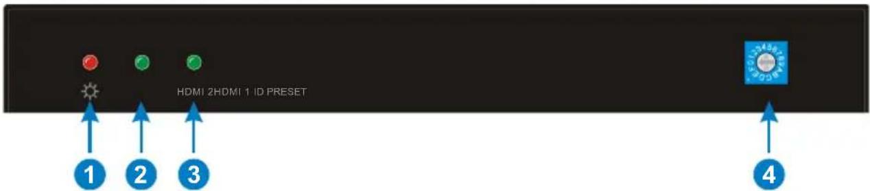
HDMI 2HDMI 1 ID PRESET ① ② ③ ④Figure 2-1 Front Panel
| No. | Name | Description |
| 1 | Power indicator | Illumine red when powered on. |
| 2 | HDMI 1 | Illumine green when the HDMI 1 signal output normally. |
| 3 | HDMI 2 | Illumine green when the HDMI 2 signal output normally. |
| 4 | ID PRESET | DIP switcher to assign the Unit ID (Range: 0~9/A~F). |
2.2 Rear Panel
text_image
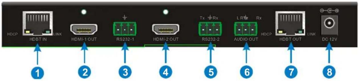
HDCP HDBT IN LINK HDMI-1 OUT RS232-1 HDMI-2 OUT Tx Rx LR Rx HDCP HDBT OUT LINK DC 12V ① ② ③ ④ ⑤ ⑥ ⑦ ⑧Figure 2-2 RearPanel
| No. | Name | Description |
| 1 | HDBT IN | Connects the HDBT output port of Matrix Switcher or HDBaseT Transmitter.HDCP indicator will turn yellow when the HDBaseT input signal is transmitted with HDCP.LINK indicator will turn green when the HDBaseT^TM Repeater is connected with Matrix Switcher or Transceiver successfully over CAT5e/6/7. |
| 2 | HDMI-1 OUT | Connects with HDMI display. |
| 3 | RS232-1 | 3-Pin phoenix connector for bidirectional RS232 control, connects with control device (e.g. PC) or the third-party device (e.g. Projector) needed to be control. |
| 4 | HDMI-2 OUT | Connects with HDMI display. |
| 5 | RS232-2 | 3-Pin phoenix connector for bidirectional RS232 control, connects with control device (e.g. PC) or the third-party device (e.g. Projector) needed to be control. |
| 6 | AUDIO OUT | 3-Pin phoenix connector for de-embedded analog audio output. |
| 7 | HDBT OUT | Connects the HDBT input port of HDBaseT Receiver or cascade another 4K HDBaseT Repeater. |
| 8 | DC 12V | Connect with 12VDC, 2A power adaptor. |
Note: Pictures shown on this manual are for reference only.
3. System Connection
3.1 Usage Precautions
- System should be installed in a clean environment and has a prop temperature and humidity.
- All of the power switches, plugs, sockets and power cords should be insulated and safety.
● All devices should be connected before power on.
3.2 System Diagram

flowchart
graph TD
    A["HDBaseT Transmitter"] -->|CATx 1080P 100m 4K×2K 70m| B["Projector"]
    A --> C["Laptop"]
    A --> D["Blu-ray DVD"]
    B --> E["HDTV"]
    B --> F["Projector"]
    B --> G["Speaker"]
    E --> H["EXT-HDRPT100 Cascade up to 6 units"]
    F --> H
    G --> H
    H --> I["Device"]
    I --> J["HDBaseT Receiver"]
    J --> K["Projector"]
    style A fill:#f9f,stroke:#333
    style H fill:#ccf,stroke:#333
    style J fill:#cfc,stroke:#333
Figure 3-1 System Connection Diagram
3.3 Connection Procedure
Step1. Connect HDMI source (such as Blue-ray DVD/PC) to HDM input port of HDBaseT transmitter with HDMI cable.
Step2. Connect HDBT output port of HDBaseT Transmitter and HDBT input port of EXT-HDRPT100M with CAT5e/6/7 cable.
Step3. Connect HDBT output port of EXT-HDRPT100M and HDBT input port of HDBaseT Receiver or next EXT-HDRPT100M with CAT5e/6/7 cable. With the daisy chain connection, user can connect with up to 6 repeaters for each source output.
Step4. Connect HDMI displayers (such as Projectors/HDTVs) to HDMI output ports of EXT-HDRPT100Ms and HDBaseT Receiver with HDMI cables.
Step5. Connect audio player (such as speaker) to the audio output port of EXT-HDRPT100M.
Step6. With RS232 control, connect the control PC to the RS232 port of HDBaseT Transmitter, and then connect the devices (such as projectors) which are needed to be controlled to RS232 ports of EXT-HDRPT100Ms and HDBaseT Receiver based on the actual need.
Step7. Connect other devices you need to HDBaseT Transmitter, EXT-HDRPT100Ms, and HDBaseT Receiver.
Step8. Make sure all devices are plugged into a working power source, and then to turn on for starting.
[Non-Text]
- System Diagram shown in this manual are for reference only, more specific schemes depend on real devices. For example, the HDBaseT Transmitter can be MX-HDBASE8X8-4K HDBaseT Matrix Switcher.
- Connect HDBT ports via straight-thru CAT5e/6/7 cable with TIA/EIAT568B standard terminations at both ends.
3.4 Application
EXT-HDRPT100M has various interesting applications such as signage on airports, bars and restaurants, Metro stations, museums. EXT-HDRPT100M could be a very good product in the educational institutions where daily activities and important information can be broadcasted using PC or media layer.
3.5 Twisted Pair Cable Connection
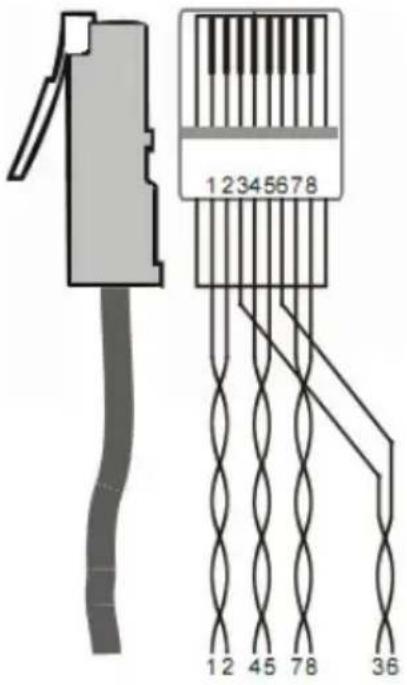
The twisted pair used in this extender must be a straight-through cable.
| TIA/EIA T568A | TIA/EIA T568B | |||
| Pin | Cable color | Pin | Cable color | |
| 1 | green white | 1 | orange white | |
| 2 | green | 2 | orange | |
| 3 | orange white | 3 | green white | |
| 4 | blue | 4 | blue | |
| 5 | blue white | 5 | blue white | |
| 6 | orange | 6 | green | |
| 7 | brown white | 7 | brown white | |
| 8 | brown | 8 | brown | |
| 1st Ground | 4--5 | 1st Ground | 4--5 | |
| 2nd Ground | 3--6 | 2nd Ground | 1--2 | |
| 3rd Group | 1--2 | 3rd Group | 3--6 | |
| 4th Group | 7--8 | 4th Group | 7--8 | |
text_image
12345678 12 45 78 36Note: Cable connectors must be metal one, the shielded layer of cable must be connected to the connector's metal shell, to make a better transmission.
4. Operation
4.1 Unit ID setup
EXT-HDRPT100M's can be cascaded up to six in this system. Through the DIP switcher "ID PRESET" to set their ID for distinguishing. For example, the Unit ID of the first EXT-HDRPT100M is set as 0, and then the second one is set as 1 and so on.
Note: The Unit ID of two or more EXT-HDRPT100M's can be set as same value for synchronous control.
4.2 RS232 Control
All devices (such as projectors) which are connected to RS232 ports of EXT-HDRPT100Ms and HDBaseT Receiver can be controlled by sending RS232 commands via the control PC.
There are three control modes: point-to-point, one-to-many and one-to-all RS232 control.
4.2.1 RS232 Command Format
flowchart
graph TD
    A["F1 AA 1F XX"] --> B["①"]
    A --> C["②"]
    A --> D["③"]
    A --> E["④"]
    A -.-> F["......"]
    style A fill:#f9f,stroke:#333
    style B fill:#ccf,stroke:#333
    style C fill:#cfc,stroke:#333
    style D fill:#fcc,stroke:#333
    style E fill:#cff,stroke:#333
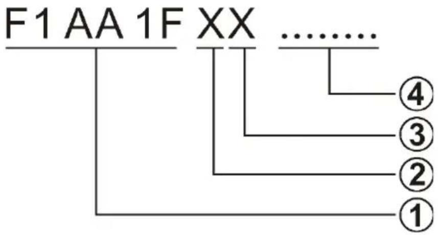
① Fixed value.
② The Unit ID of the EXT-HDRPT100M, X=1\~9/A\~F
③ The RS232 port of EXT-HDRPT100M, X=1\~3:
● 1: "RS232-1" port
● 2: "RS232-2" port
● 3: Both "RS232-1" and "RS232-2" ports
④ Hexadecimal characters represent the control command data, and the length of character is unrestricted. For specific commands, please refer to the user manual of the devices which are needed to be control.
Note: When the value of "XX" is FF, send the command "F1 AA 1F FF ... ..." to
control all devices which are connected to RS232 ports of EXT-HDRPT100Ms and HDBaseT Receiver at the same time.
| RS232 Control Mode | Description |
| Point-to-Point | In this mode, control one of the devices which are connected to RS232 ports of EXT-HDRPT100Ms.For example:F1 AA 1F 32 ... ...Send this command to control the device which is connected to the “RS232-2” port of the EXT-HDRPT100M whose Unit ID is 3. |
| One-to-Many | In this mode, control several devices which are connected to RS232 ports of EXT-HDRPT100Ms.For example:F1 AA 1F 01 E3 ... ...Send this command to control three devices:01:The “01” represents the device which is connected to the “RS232-1” port of the EXT-HDRPT100M whose Unit ID is 0.E3:The “E3” represents the two devices which are connected to both “RS232-1” and “RS232-2” ports of the EXT-HDRPT100M whose Unit ID is E. |
| One-to-All | In this mode, control all devices which are connected to RS232 ports of EXT-HDRPT100Ms and HDBaseT Receiver at the same time.For example:F1 AA 1F FF ... ... |
Note: When control the two devices which are connected to both "RS232-1" and "RS232-2" ports of the EXT-HDRPT100M, it is normal that the feedback code may be garbled.
4.2.2 Installation/uninstallation of RS232 Control Software
- Installation
Copy the control software file to the control PC connected with HDBaseT Transmitter.
- Uninstallation
Delete all the control software files in corresponding file path.
4.2.3 Basic Settings
Double-click the software icon to run RS232 Control Software.
Here we take the software CommWatch.exe as example. The icon is showed as below:

CommWatch.exe
The interface of the control software is showed as below:

text_image
Parameter Configuration area UART (SerialPort) Test Tool (V1.0) — HTTP://WWW.SL.COL.CN PORT Com1 BaudRa 9600 Parity pNone Byte 8 Stop 1 Reset Clear Save To File Hex View Stop View Auto Clear View New Line Hex Send Mode Send Auto Send Interval 1000 ms Load File Counter Reset Clear 2013-05-08 14:03:35 Send:0 Receive:0 V1.0 Monitoring area, indicates if the command sent works. Command Sending areaPlease set the parameters of COM number, bound rate, data bit, stop bit and the parity bit correctly, and then tick the "Hex Send Mode", you are able to send command in Command Sending Area.
● Baud rate: support 2400、4800、9600、19200、38400、57600、115200;
- Data bit: 8;
- Stop bit: 1;
- Parity bit: none.
4.3 EDID Management
An essential part of operation is the EDID table, which is transmitted to the source from the HDBaseT Transmitter input.
The EXT-HDRPT100M features advanced built-in EDID management function, and it should follow the below rules:
- When the "HDMI-1 OUT", "HDMI-2 OUT" and "HDBT OUT" ports are connected with devices, the input source device will firstly read the EDID from the HDBT output device (such as HDTV) which is connected to the HDMI output port of HDBaseT Receiver. If disconnecting the HDBT output device, the EDID data don't need to be read again. If changing the HDBT output device, the EDID data will be read again from the new device.
- When the "HDMI-1 OUT", "HDMI-2 OUT" ports are connected with devices, but the "HDBT OUT" port aren't connected with any device, the input source device will firstly read the EDID from the HDMI-1 output device of the last repeater (such as HDTV). If disconnecting the HDMI-1 output device, the EDID data don't need to be read again.
Note: The input source will re-read the EDID date according the above rules when the system is powered down and reset.
4.4 HDCP Management
The EXT-HDRPT100M offers advanced HDCP management to allow greater compatibility with other devices. The output will always be encrypted or unencrypted, following the status of the source content. If the content is encrypted, the output of the HDBaseT receiver will be encrypted; if the content is unencrypted, the output of the HDBaseT receiver will be unencrypted.
The EXT-HDRPT100M HDCP2.2 compliant and backward compatible to the down-level version.
| Input | Output |
| HDCP | HDCP |
| HDCP2.2 | HDCP1.4 |
| HDCP1.4 or lower level version | HDCP1.4 or lower level version |
5. Specification
| Input & Output | |
| Input Port | HDBT IN |
| Input Connector | One (1) RJ45 Receptacle |
| Input Video Signal | The max resolution is up to 4Kx2K/60Hz 4:2:0, compatible with HDCP2.2 |
| Output Port | HDMI-1 OUT; HDMI-2-OUT; HDBT OUT; AUDIO OUT |
| Output Connector | Two (2) HDMI Type A Receptacle; One (1) RJ45 Receptacle; One (1) 3-Pin phoenix connector |
| Output Video Signal | The max resolution is up to 4Kx2K/60Hz 4:2:0, compatible with HDCP1.4 |
| Embedded Audio Signal | Supports PCM/Dolby/DTS |
| Output Analog Audio Signal | Supports PCM |
| Analog Audio Frequency Response | 20 Hz to 20 kHz, ±3 dB |
| Transmission Mode | HDBaseT |
| Control Part | |
| RS232 Control Ports | RS232-1; RS232-2 |
| RS232 Connector | Two (2) 3-Pin phoenix connector |
| Baud Rate | 9600 |
| General | |
| Power Supply | Input: 100VAC~240VAC, 50/60Hz Output: 12VDC, 2A |
| Maximum Power Consumption | 14W |
| Work Temperature | -10 ~ +55°C |
| Humidity | 10% ~ 90% |
| Dimension (W*H*D) | 7.8 x .98 x 3.93 inches |
| Net Weight | 0.8 lb. |
Note: All nominal levels are at ±10%.
6. Panel Drawing

text_image
HDB-TH HDB-T OUT R3202 HDMI-2 OUT R3202-2 ALD-IO-OUT HDB-1 OUT DC KEY 9 mm 105 mm 100 mm 25 mm 200 mm KanexPro® EXT HDRPT100M 4K HDBaseT "Repeater7. Troubleshooting & Maintenance
| Problems | Causes | Solutions |
| Output images in display show with ghost | Incorrect setting on the display | Check the display's setting |
| A cable of bad quality | Try another high quality connection cable | |
| No output image | No signal at the input / output end | Check with oscilloscope or multimeter if there is any signal at the input / output end. |
| Fail or loose connection | Make sure the connection is good | |
| Cannot control the device by control device (e.g. a PC) through RS232 port | Wrong RS232 communication parameters | Make sure the RS232 communication parameters are correct. |
| The device has already been broken | Send it to authorized dealer for repairing. | |
| Static becomes stronger when connecting the video connectors | Bad grounding | Check the grounding and make sure it is connected well. |
If your problem persists after following the above troubleshooting steps, seek further help from authorized dealer or our technical support.
8. After-sales Service
If there appear some problems when running the device, please check and deal with the problems reference to this user manual. Any transport costs are borne by the users during the warranty.
1) Product Limited Warranty: It is warranted that the product will be free from defects in materials and workmanship for three years, which starts from the first day you buy this product (The purchase invoice shall prevail).
Proof of purchase in the form of a bill of sale or receipted invoice which is evidence that the unit is within the Warranty period must be presented to obtain warranty service.
2) What the warranty does not cover:
- Warranty expiration. - Factory applied serial number has been altered or removed from the product.
● Damage, deterioration or malfunction caused by:
● Normal wear and tear.
- Use of supplies or parts not meeting our specifications.
- No certificate or invoice as the proof of warranty.
● The product model showed on the warranty card does not match with the model of the product for repairing or had been altered.
● Damage caused by force majeure.
● Servicing not authorized.
- Any other causes which does not relate to a product defect.
● Delivery, installation or labor charges for installation or setup of the product.
3) Technical Support: Email to our after-sales department or make a call, please inform us the following information about your cases.
● Product version and name.
● Detailed failure situations.
● The formation of the cases.
Remarks: For any questions or problems, please try to get help from your local distributor.
9. Warranty
A. LIMITED WARRANTY
KanexPro™ warrants that (a) its products (the "Product") will perform greatly in agreement with the accompanying written materials for a period of 36 months (3 full years) from the date of receipt and (b) that the product will be free from defects in materials and workmanship under normal use and service for a period of 3 years.
B. CUSTOMER REMEDIES
KanexPro's entire liability and Customer's exclusive remedy shall be, at KanexPro option, either return of the price paid for the product, or repair or replacement of the Product that does not meet this Limited Warranty and which is returned to KanexPro with a copy of customers' receipt. This Limited Warranty is void if failure of the Product has resulted from accident, abuse, or misapplication. Any replacement Product will be warranted for the remainder of the original warranty period of 3 years, whichever is longer.
C. NO OTHER WARRANTIES
To the maximum extent permitted by applicable law, KanexPro disclaims all other warranties, either express or implied, including, but not limited to implied warranties of merchantability and fitness for a particular purpose, with regard to the product and any related written materials. This limited warranty gives customers specific legal rights. Customers may have other rights depending on the jurisdiction.
D. NO LIABILITY FOR DAMAGES
To the maximum extent permitted by applicable law, in no event shall KanexPro be liable for any damages whatsoever (including without limitation, special, incidental, consequential, or indirect damages for personal injury, loss of business profits, business interruption, loss of business information, or any other pecuniary loss) arising out of the use of or inability to use this product, even if KanexPro has been advised of the possibility of such damages.
KanexPro®
1405 pioneer street
Brea, CA 92821