7170-0166-02 - Accessory Gamber-Johnson - Free user manual and instructions
Find the device manual for free 7170-0166-02 Gamber-Johnson in PDF.

User questions about 7170-0166-02 Gamber-Johnson
0 question about this device. Answer the ones you know or ask your own.
Ask a new question about this device
Download the instructions for your Accessory in PDF format for free! Find your manual 7170-0166-02 - Gamber-Johnson and take your electronic device back in hand. On this page are published all the documents necessary for the use of your device. 7170-0166-02 by Gamber-Johnson.
USER MANUAL 7170-0166-02 Gamber-Johnson
INSTALLATION INSTRUCTIONS
Product Revision
7160-0410, 7160-0412, 7170-0165, 7170-0166

Rev.N
Form
INST-568
FORD NGPI CONSOLE SEDAN & UTILITY, 2012+
Printing Spec: PS-004
text_image
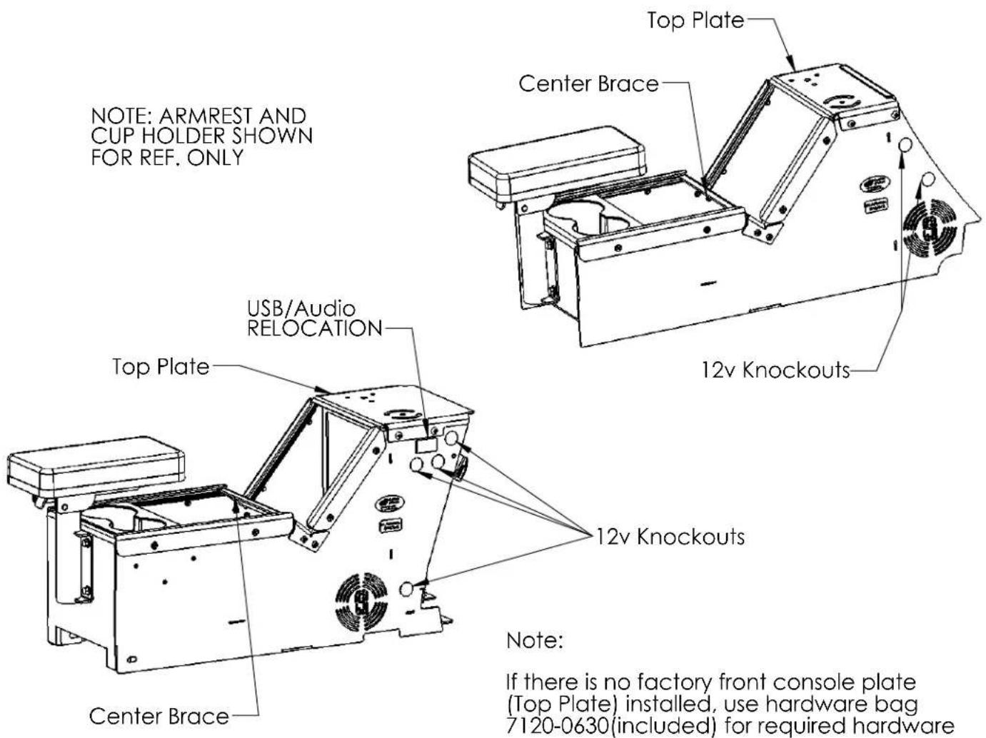
NOTE: ARMREST AND CUP HOLDER SHOWN FOR REF. ONLY USB/Audio RELOCATION Top Plate Center Brace Top Plate Center Brace 12v Knockouts 12v Knockouts Note: If there is no factory front console plate (Top Plate) installed, use hardware bag 7120-0630(included) for required hardwareSedan:
- Remove the stock tunnel plate by removing the 6 bolts.
- The harness on the right side of the YAW sensor (located on the transmission tunnel) may impede box installation. For ease of installation, pull up on harness to disconnect the push fastener attaching the harness to the transmission tunnel.
-
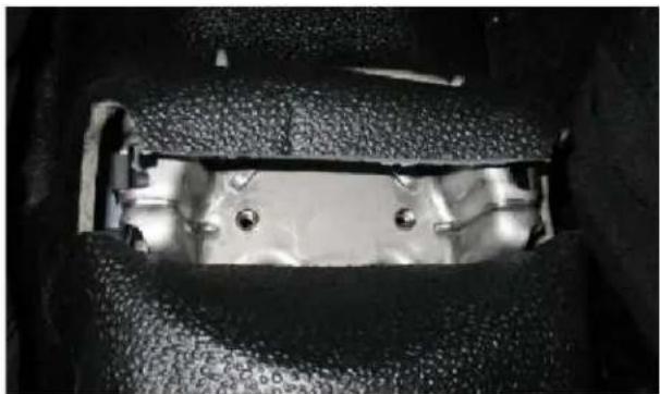
The rear mounting points may be hidden under the flooring. Carefully cut the flooring as shown to expose the mounting points (Fig 1).
-
Slide console box into place.
-
Attach console to transmission tunnel using OEM hardware.
Utility:
- Remove the lower dash trim panels on either side of the dash (Fig 2).
- Remove the stock tunnel plate by removing the 6 bolts.
- Remove the USB/Audio/12v jack Trim Panel (Fig 2) and disconnect the USB, Audio and 12v cables.
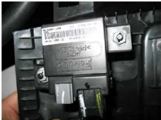
- Relocate OEM Module to under dash area (Fig. 3)
natural_image
Close-up of a mechanical component with metallic parts and mounting holes (no visible text or symbols)Fig 1 - Rear Mounting Bracket, Carpet Cut to Revel Threaded Inserts

text_image
Lower Dash Trim Panel USB/AudioFig 2 - Utility Lower Dash
text_image
B-2004568 100 V 100 V 100 V B-2004568 100 V 100 V 100 V B-2004568 100 V 100 V 100 V B-2004568 100 V 100 V 100 V B-2004568 100 V 100 V 100 VFig. 3 - OEM Module located on backside of trim Panel
- The harness on the right side of the YAW sensor (located on the transmission tunnel) may impede box installation. For ease of installation, pull up on harness to disconnect the push fastener attaching the harness to the transmission tunnel.
- Remove the Top Plate from the console box.
- Slide the console box into place.
- Attach the console to the transmission tunnel using the OEM hardware.
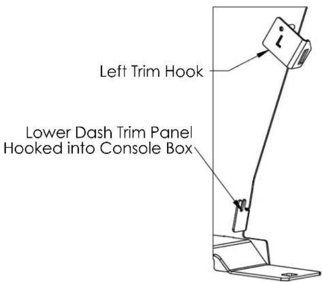
- Attach the Lower Dash Trim Panel to the console box by placing the lower lip of the Trim Panel into the hook on the bottom of the console box (Fig 4).
- Attach the top of the Lower Dash Trim Panel to the console box using the supplied Trim Hooks (Fig 4). Note that the left Trim Hook has an "L" cut out of it. It may be easier to remove the Top Plate when installing the Lower Dash Trim Panels.
- Snap the Lower Dash Panels back into place.
text_image
Left Trim Hook Lower Dash Trim Panel Hooked into Console BoxFig 4 - Installing Lower Dash Trim Panels
Sedan and Utility:
Install the armrest (7160-0409 & 7160-0411) into the tube and adjust to the desired height/orientation then tighten the bolt under the armrest. Note: Armrest is not included with 7160-0410 or 7160-0412 but can be ordered separately. The armrest mounting bracket can be flipped over to lower the armrest if desired or if used with a Printer Armrest.
The cup holder (MCS-INTCUP) can be placed anywhere along the horizontal length of the box. Note: The cup holder is not included with 7160-0410 or 7160-0412 but can be ordered separately.
The Top Plate and Center Brace on both console boxes are designed to be removable to aid in installation and cable routing. If either item is removed Gamber-Johnson recommends reinstalling the screws with a drop of Blue 242 Loctite to prevent loosening. Torque the (4) top plate bolts to 65-80 in-lbs when reinstalling.
Both boxes have knockouts for 12v accessory outlets (7160-0063). To install simply punch out the desired knockout and install the 12v outlet. The 12v outlet will need to be hardwired into the vehicles power system. An additional 12v accessory outlet can be purchased for the second knockout if desired.