RNK46UHF - Suivi ORION - Free user manual and instructions
Find the device manual for free RNK46UHF ORION in PDF.

User questions about RNK46UHF ORION
0 question about this device. Answer the ones you know or ask your own.
Ask a new question about this device
Download the instructions for your Suivi in PDF format for free! Find your manual RNK46UHF - ORION and take your electronic device back in hand. On this page are published all the documents necessary for the use of your device. RNK46UHF by ORION.
USER MANUAL RNK46UHF ORION
natural_image
3D rendering of a rectangular metallic panel or enclosure with a flat top and thin border (no text or symbols)VIDEO WALL SOLUTION
(42\~82 inches)
1. SAFETY INSTRUCTION
※ Follow this safety instruction to use the monitor properly and prevent the damages.
※ This safety instruction has “Warning” & “Caution” as below

Warning - If the user does not follow this instruction, it may cause the serious damage to the user.

Caution - If the user does not follow this instruction, it may cause the slight damage to the user or cause some damages to the monitor.
※ Keep this user's guide book for later use.

Warning
Never remove the back over and touch the inside of the monitor. If you need a service, please contact the service center.

natural_image
Cartoon illustration of a smiling computer monitor character with arms and legs, holding a pen and a cross (no text or symbols)Keep away the monitor from the direct sunlight and a heating appliance.
natural_image
Cartoon illustration of a sad computer monitor with steam rising, next to a steaming cup and sun (no text or symbols)Never push objects of any kind into this product as they may result in a risk of fire or electric shock.

natural_image
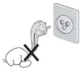
Cartoon illustration of a computer monitor with a sad face and a crossed-out '100' sign, symbolizing stress or urgency (no text present)Connect the power code to the wall outlet tightly. If the power code or plug are defective and the wall outlet is not tight, please do not use them.

natural_image
Cartoon illustration of a computer monitor with a sad face and a starburst, connected to a power outlet (no text or symbols)
Warning
Do not install this monitor on the outside and near water. If may cause damage to the product, electric shock and fire.
natural_image
Illustration of a steaming pot and a computer monitor with a sad face, accompanied by a crossed-out 'X' symbol (no text or labels)For cleaning do not use liquid cleaners. Never touch the power plug with wet-hands.
text_image
Cartoon illustration showing a computer monitor with a sad face, a spray bottle, and a droplet with a crossed-out 'No' symbol, alongside a small card with a dollar sign.When lightning and thundering, unplug the monitor from the wall outlet and never touch it.
natural_image
Cartoon illustration of a computer monitor character with a sad face and lightning bolts, next to an electrical plug (no text or symbols)Unplug this product from the wall outlet, when it does not operate for a long time.

natural_image
Cartoon illustration of a sad computer monitor with a phone emitting sound waves, no text or symbols presentWhen smoking and noising from the monitor, unplug the product from the wall outlet and contact a service center.

natural_image
Cartoon illustration of a smiling computer monitor with a waving hand and question mark symbols (no text or labels)
WARNING: How to fix
Do not open this product as it contains high voltage inside.
It may create an electric shock.
It the user disassembles and remove the back cover, it does not make sure to make up for the damages and do a service and exchange the monitor.

Cautions
Install this monitor some distance From the wall and do not install unless Proper ventilation is provided.

natural_image
Cartoon illustration of a smiling computer monitor with arms and legs, no text or symbols presentPlace this product on a stable place. If not, it may fall, causing serious Damages to the monitor and people.

natural_image
Cartoon illustration of a computer monitor with a sad face and waving hands (no text or symbols)The openings must not be blocked by curtain, rug or other similar surface.

natural_image
Cartoon illustration of a sad computer monitor with arms and frowning faces (no text or symbols)When carrying this monitor, be careful not to damage the panel and drop it. It may cause some trouble.

natural_image
Cartoon illustration of a smiling computer monitor with arms extended (no text or symbols)Before carrying the monitor, tum it off and Unplug the signal cables and the power code From the wall outlet.

natural_image
Cartoon illustration of a smiling computer monitor with a power button and plug, connected to an electrical outlet (no text or symbols)Take the power plug out from the wall outlet. Do not pull the cable. It may snap the inner-wires and cause overheating and fire.
natural_image
Illustration of a hand pointing at an electrical outlet with a cross mark (no text or symbols)
Cautions
Install this monitor about 50cm far from the eyes and an angle of 0\~15 degrees below eyes. Too close installation may cause having weak sight.
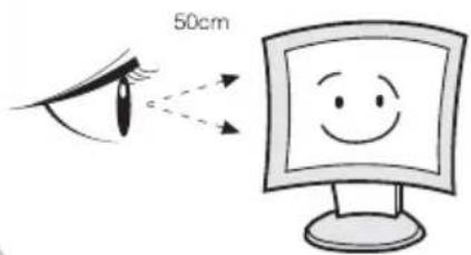
text_image
50cmDo not press the LCD panel with hands or the sharpened material hardly.

natural_image
Cartoon illustration of a sad computer monitor character with arms and legs, holding a blank sign (no text or symbols present)For cleaning, unplug the monitor from the Wall outlet. Do net use the liquid cloth. Use the soft cloth.

natural_image
Simple line drawing of a computer monitor with a smiling face, next to a blank envelope and a square (no text or symbols)Do not use the chemical liquid for cleaning. It may cause fading and breakage.
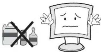
text_image
Illustration showing a crossed-out bottle and a sad face on a computer monitor, symbolizing food safety or toxicity.WARNING: TO REDUCE THE RISK OF ELECTRIC SHOCK, DO NOT EXPOSE THIS EQUIPMENT TO RAIN OR WATER.
Instructions for Disposal of Electrical and Electronic Equipment in Private Households
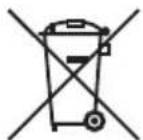
Disposal of used Electrical and Electronic Equipment (Applicable in the European Union and other European countries with garbage separate disposal and collection methods)
This symbol on the product, or in the related documents in the package, indicates that this product shall not be treated as normal household waste. Instead, it should be taken to a proper applicable collection point or depot for the recycling of electrical and electronic equipment.
By ensuring this product is disposed of correctly, you will help prevent possible negative consequences for the environment and human health, which could otherwise be caused by inappropriate waste handling of this product. The recycling of materials will help to conserve natural resources.
For more detailed information about recycling of this product, please contact your local city authority, your household waste disposal service or the place where you purchased the product.
2. FCC RF INTERFERENCE STATEMENT
NOTE
This equipment has been tested and found to comply with the limits for a Class A digital device, pursuant to Part 15 of the FCC Rules. These limits are designed to provide reasonable protection against harmful interference in a residential installation. This equipment generates, uses and can radiate radio frequency energy and, if not installed and used in accordance with the instructions, may cause harmful interference to radio communications. However, there is no guarantee that interference will not occur in a particular installation. If this equipment does cause harmful interference to radio or television reception which can be determined by turning the equipment off and on, the user is encouraged to try to correct the interference by one or more of the following measures.
- Reorient or relocate the receiving antenna.
- Increase the separation between the equipment and receiver.
- Connect the equipment into an outlet on a circuit different from that to which the receiver is connected.
- Consult the dealer or an experienced radio, TV technician for help.
- Only shielded interface cable should be used.
Finally, any changes or modifications to the equipment by the user not expressly approved by the grantee or manufacturer could void the users authority to operate such equipment.
DOC COMPLIANCE NOTICE
This digital apparatus does not exceed the Class A limits for radio noise emissions from digital apparatus set out in the radio interference regulation of Canadian Department of communications.
TABLE OF CONTENTS
- SAFETY INSTRUCTION 2
1-1 Warning
1-2 Caution
-
FCC STATEMENT 6
-
INSTALLATION 8
3-1 Parts
3-2 How to Install
- OSD MENU SETTING 13
4-1 Mode Setting
4-2 Menu Setting
- FEATURES 21
- MECHANICAL DRAWING 22
- TROUBLESHOOTING 23
3. INSTALLATION
3-1 Parts
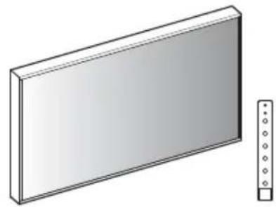
natural_image
3D illustration of a rectangular panel with a vertical scale on the right side (no text or symbols)LCD Monitor & Keypad
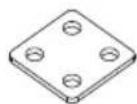
Joint Bracket
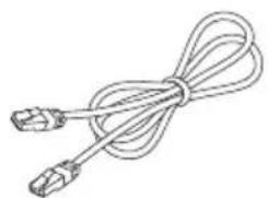
natural_image
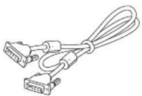
Line drawing of a cable with two connectors (no text or symbols)UTP Cable DVI Cal
natural_image
Line drawing of two connected USB cables (no text or symbols)e
natural_image
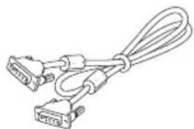
Line drawing of a broadband cable with two 20-pin connectors (no text or symbols)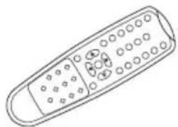
natural_image
Line drawing of a remote control with buttons and dials (no text or symbols)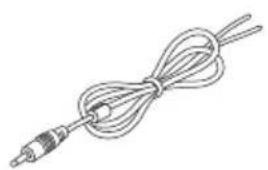
natural_image
Line drawing of a coiled cable or wire with a terminal connector (no text or symbols)Trigger Cable Power

natural_image
Line drawing of a cable with a plug and connector (no text or symbols)e Controller
Battery Install CD
3-2 How to Install
KEYPAD CONTROLLER

text_image
KEYPAD This KEYPAD is attached to a magnet, so you can freely paste UTP Cable (1.5m) EXIT MENU SOURCE AUTO VOLUME SELECT POWERIf you want to replace with a longer cable Please purchase separately
SHORT KEY FUNCTION
| OSD KEY FUNCTION | |
| EXIT MENU | On/off the OSD menu or exit the source selection menu |
| ▼SOURCE | Move the cursor to choose on the OSD menu |
| Select the source on the INPUT menu | |
| △AUTO | Move up the cursor to choose on the OSD menu |
| Activate the auto adjustment of RGB source | |
| ◀VOLUME | Control down on the OSD menu or move to the previous menu |
| Volume down | |
| ▷SELECT | Select the OSD menu |
| Control up on the OSD menu | |
| Volume up | |
| ○/|POWER | Turn the power ON or OFF. There will be a few seconds delay before the display appears. The power LED (next to the power switch) lights with green when the power is turned ON. The power is turned off by pressing the power switch again and the power LED goes red. |
CONNECTION
text_image
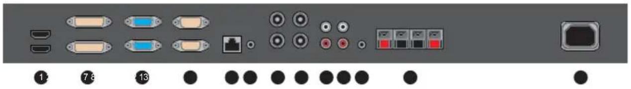
Diagram of a computer rack front panel with labeled ports and indicator lights1 HDMI
HDMI Signal input / loop output VIDEO-2 Signal input / loop output
8 VIDEO-2 IN / OUT
2 DVI
DVI Signal input / loop output Stereo audio input for VIDEO-1
9 AUDIO (VIDEO-1)
3 VGA 10 AUDIO (VIDEO-2)
VGA (PC RGB) Signal input / loop output Stereo audio input for VIDEO-2
4 RS-232 IN / OUT 11 TRIGGER
SERIAL Cable input / output for RS-232 TRIGGER Signal input
5 KEYPAD
UTP Cable input for KEYPAD
6 AUDIO (PC)
Stereo audio input for VGA
7 VIDEO-1 IN / OUT
VIDEO-1 Signal input / loop output
12 SPEAKER OUT Stereo speaker output
13 AC POWER
AC 100-240V input
14 DC24V
DC 24V (Adapter) input
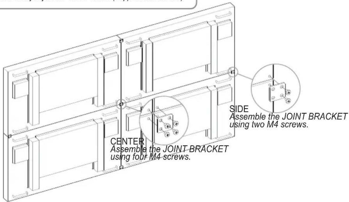
- You can combine two or more monitors, and configure the VIDEO WALL.
- If you want to configure VIDEO WALL, please contact your dealer or a professional installer.
- JOINT BRACKET helps to easily adjust the VIDEO WALL. (Supplied with monitor)
text_image
CENTER Assemble the JOINT BRACKET using four M4 screws. SIDE Assemble the JOINT BRACKET using two M4 screws.CABLES CONNECTION
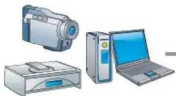
* Cable connection order, it may be different from the order of the 'SET ID' or 'SEQUENCE' (Refer to page 15\~17)
natural_image
Illustration of three electronic devices: a camera, a printer, and a laptop (no text or symbols visible)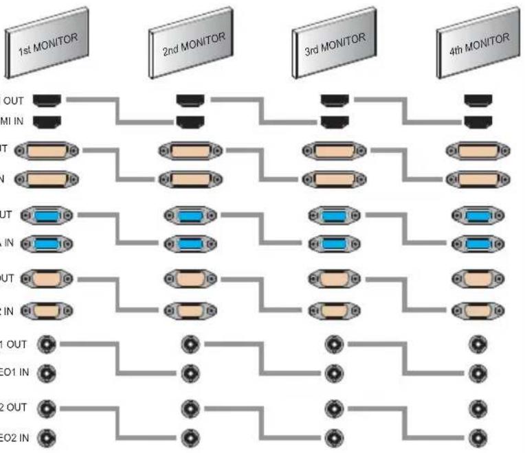
flowchart
graph TD
    subgraph_Moniters_1["1st MONITOR"]
        A1["Input"] --> B1["OUT"]
        A2["Input"] --> B2["IN"]
        A3["Input"] --> B3["OUT"]
        A4["Input"] --> B4["IN"]
        A5["Input"] --> B5["OUT"]
        A6["Input"] --> B6["IN"]
    end

    subgraph_Moniters_2["2nd MONITOR"]
        A7["Input"] --> B7["OUT"]
        A8["Input"] --> B8["IN"]
        A9["Input"] --> B9["OUT"]
        A10["Input"] --> B10["IN"]
        A11["Input"] --> B11["OUT"]
        A12["Input"] --> B12["IN"]
    end

    subgraph_Moniters_3["3rd MONITOR"]
        A9["Input"] --> B13["OUT"]
        A10["Input"] --> B14["IN"]
        A11["Input"] --> B15["OUT"]
        A12["Input"] --> B16["IN"]
    end

    subgraph_Moniters_4["4th MONITOR"]
        A13["Input"] --> B17["OUT"]
        A14["Input"] --> B18["IN"]
        A15["Input"] --> B19["OUT"]
        A16["Input"] --> B20["IN"]
    end

    Moniters_5["5th MONITOR"]
    Moniters_6["6th MONITOR"]
    Moniters_7["7th MONITOR"]
    Moniters_8["8th MONITOR"]
    Moniters_9["9th MONITOR"]
    Moniters_10["10th MONITOR"]
* Please install the COMMANDER (Video Wall Control Program) for remote control of the monitors through the computer. For information about installing and using COMMANDER, please refer to the installation disk that came with the monitor.
REMOTE CONTROLLER
text_image
POWER MUTE VIDEO VIDEO2 VGA AUTO COLOR TEMP DISHOW S.SET SCAN MODE PIP VOL-VOL MENUEXT KEY LOCK P.INPUT P.LOCATION P.SIZE P.SWAP STILL A B CA MODE SELECT MENU
VIDEO 1 (Only 40 inches or more) Select VIDEO 1 mode
DVI Select DVI mode
HDMI Select HDMI mode
VIDEO 2 (Only 40 inches or more) Select VIDEO 2 mode
VGA (RGB) Select VGA mode
B OSD CONTROL MENU
POWER Turn ON / OFF the monitor
AUTO Auto adjust position of the screen (in VGA mode)
SCAN MODE Select the scan mode of the screen
MENU / EXIT Activate and exit the OSD menu
STILL Freeze the current image
MUTE Turn ON / OFF the sound
COLOR TEMPERATURE Select color temperature of the screen
VOL- / VOL+ Increase / Decrease the volume level
KEY LOCK Locking the button (Prevent operation)
C PIP CONTROL MENU
S. SET Select between main and PIP audio input
P. INPUT Select an input source for PIP mode
P. SIZE Select a size for PIP mode
PIP Activates PIP/PBP mode
P. LOCATION Select a location for PIP mode
P. SWAP Swap between main and PIP input
4. OSD MENU SETTING
4-1 Mode Setting
text_image
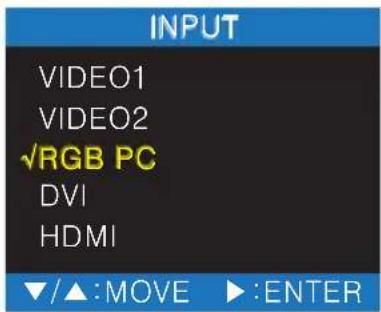
INPUT VIDEO1 VIDEO2 ✓RGB PC DVI HDMI ▼/▲:MOVE ▶:ENTER- Use Source button and then ▲ or ▼ button to move the source.
- Press the ▶ button to select the source.
- Press the MENU/EXIT button to exit the INPUT menu.
| VIDEO1 Select VIDEO1 Mode (Only 40 inches or more) |
| VIDEO2 Select VIDEO2 Mode (Only 40 inches or more) |
| RGB PC Select VGA Mode |
| DVI Select DVI Mode |
| HDMI Select HDMI mode |
4-2 Menu Setting
PICTURE
text_image
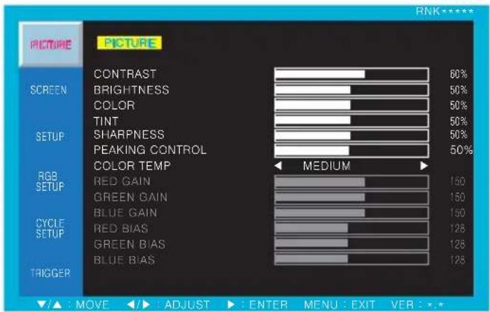
PICTURE CONTRAST 60% BRIGHTNESS 50% COLOR 50% TINT 50% SHARPNESS 50% PEAKING CONTROL 50% COLOR TEMP MEDIUM RGB SETUP RED GAIN 150 GREEN GAIN 150 BLUE GAIN 150 RED BIAS 128 GREEN BIAS 128 BLUE BIAS 128 CYCLE SETUP TRIGGER ▲ : MOVE ◀: ADJUST ▶: ENTER MENU: EXIT VER: *.*- Press the MENU key to access menu.
- Use the ▲ or ▼ key to choose PICTURE.
- Press the ▶ key to enter the PICTURE menu.
- Use the ▲ or ▼ key to choose an item of PICTURE.
- Use the ◀ or ▶ key to adjust the setting on a selected item.
| ITEM FUNCTION | DEFAULT VALUE AVAILABLE MODE | ||
| CONTRAST Adjust the contrast level of color All modes | 60% | ||
| BRIGHTNESS Adjust the brightness level of color All modes | 50% | ||
| COLOR Adjust the depth of color VIDEO, HDMI | 50% | ||
| TINT Adjust the tint of color (only NTSC signal) VIDEO, HDMI | 50% | ||
| SHARPNESS Adjust the sharpness of picture VIDEO, HDMI | 50% | ||
| PEAKING CONTROL Adjust the sharpness of outline | 50% HDMI | ||
| COLOR TEMP | Set the color temperature of screen(MEDIUM, WARM, USER, COOL)* USER - Adjust the gain and bias of RED, GREENand BLUE from 0 to 255 | MEDIUM | All modes |
SCREEN

text_image
PICTURE SCREEN H MONITORS V MONITORS ◀ 01 SEQUENCE H GAP V GAP SCAN MODE PIP PIP INPUT PIP SWAP PIP SIZE PIP LOCATION 01 01 00 00 FULL OFF VIDEO2 SMALL R/B RGB SETUP CYCLE SETUP TRIGGER ▼/▲ : MOVE ◀/► : ADJUST ► : ENTER MENU : EXIT VER : *.*- Press the MENU key to access menu.
- Use the ▲ or ▼ key to choose SCREEN.
- Press the ▶ key to enter the SCREEN menu.
- Use the ▲ or ▼ key to choose an item of SCREEN.
- Use the ◀ or ▶ key to adjust the setting on a selected item.
| ITEM FUNCTION | DEFAULT VALUE AVAILABLE MODE | ||
| H MONITORS | Set the total number of horizontally installed monitors on the video wall situation (01 ~ 99) | 01 | All modes |
| V MONITORS | Set the total number of vertically installed monitors on the video wall situation (01 ~ 99) | 01 | All modes |
| SEQUENCE | Set the sequence of installed monitors on the video wall situation (01 ~ 99) | 01 | All modes |
| H GAP | Set the horizontal gap between adjacent panels caused by bezel width (00 ~ 99) | 00 | All modes |
| V GAP | Set the vertical gap between adjacent panels caused by bezel width (00 ~ 99) | 00 | All modes |
| SCAN MODE | Select the scan mode of the screen (FULL, REAL,*UNDER, OVER, 4:3) | FULL | All modes |
| PIP | Activate PIP/PBP mode (OFF, ON, DW1, DW2) (Only 40 inches or more) | HDMIOFF |
*UNDER : It does not appear in HDMI mode
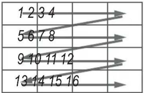
SEQUENCE numerical order
text_image
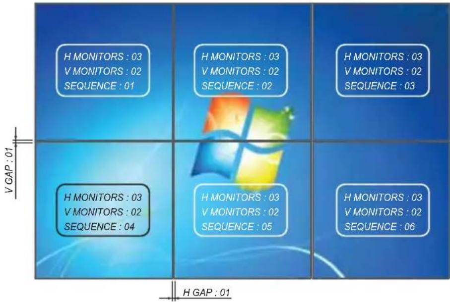
1 2 3 4 5 6 7 8 9 10 11 12 13 14 15 16ex) In case of 3X2 Video Wall Setting
text_image
H MONITORS : 03 V MONITORS : 02 SEQUENCE : 01 H MONITORS : 03 V MONITORS : 02 SEQUENCE : 02 H MONITORS : 03 V MONITORS : 02 SEQUENCE : 03 H MONITORS : 03 V MONITORS : 02 SEQUENCE : 04 H MONITORS : 03 V MONITORS : 02 SEQUENCE : 05 H MONITORS : 03 V MONITORS : 02 SEQUENCE : 06 H GAP : 01SCAN MODE
REAL : Display original images entered from the source intactly
UNDER : Display the image on the smaller area than the screen Original image is fully displayed.
OVER : Display the image on the broader area than the screen Original Image is cut off on the edge.
4:3 : Display the image to 4:3 aspect ratio
PIP
Default Setting is OFF and changeable to ON, DW1 and DW2 PIP/PBP modes.
OFF : PIP/PBP modes are not activated.
ON : Switch on PIP/PBP mode
DW1: change to Double Window mode 1
DW2 : change to Double Window mode 2
After selecting PIP/PBP modes, following items are activated.
PIP INPUT : Select an input source for PIP image (VIDEO 1, VIDEO 2)
PIP SWAP : Swap main picture and sub picture
PIP SIZE : Select the size of PIP image (SMALL, NORMAL, LARGE)
PIP LOCATION : Select the position of PIP image (R/B, L/B)
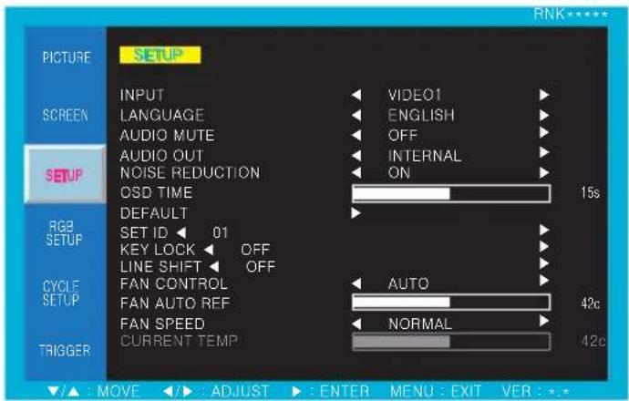
SETUP
text_image
PICTURE SETUP INPUT LANGUAGE AUDIO MUTE AUDIO OUT NOISE REDUCTION CSD TIME DEFAULT SET ID 01 KEY LOCK OFF LINE SHIFT OFF FAN CONTROL FAN AUTO REF FAN SPEED CURRENT TEMP VIDEO1 ENGLISH OFF INTERNAL ON 15s RGB SETUP CYCLE SETUP AUTO 42c NORMAL 42c TRIGGER ▲: MOVE ▶: ADJUST ▶: ENTER MENU: EXIT VER: *.*- Press the MENU key to access menu.
- Use the ▲ or ▼ key to choose SETUP.
- Press the ▶ key to enter the SETUP menu.
- Use the ▲ or ▼ key to choose an item of SETUP.
- Use the ◀ or ▶ key to adjust the setting on a selected item.
| ITEM FUNCTION | DEFAULT VALUE AVAILABLE MODE | ||
| INPUT Select the input source for main picture All modes | |||
| LANGUAGE | Set the language of OSD(ENGLISH, ITALIAN, FRENCH, SPANISH, GERMAN) | ENGLISH | All modes |
| AUDIO MUTE Turn on/off the audio output All modes | OFF | ||
| AUDIO OUT | Select the speaker for audio output(INTERNAL, EXTERNAL) | INTERNAL | All modes |
| NOISE REDUCTION Set the noise reduction mode All modes | ON | ||
| OSD TIME Set the time duration of OSD menu (5~30s) All modes | 15s (seconds) | ||
| DEFAULT | Factory default setting | All modes | |
| SET ID | Allocate an ID of the set for RS-232 control | 01 | All modes |
| KEY LOCK | Lock the key action (Prevent operation) | OFF | All modes |
| LINE SHIFT | Move the image a little instantaneously to protectthe screen | OFF | All modes |
| FAN CONTROL | Select the control method of FAN (AUTO, ON, OFF) | AUTO | All modes |
| FAN AUTO REF | Set the reference temperature for automatic FANcontrol (20~60c) | 42c (celsius) | All modes |
| FAN SPEED | Select the speed of FAN (NORMAL, FAST, SLOW) | NORMAL | All modes |
| CURRENT TEMP | Display the current temperature | All modes | |
To cancel KEY LOCK mode
Remote Controller : Press KEY LOCK button
Keypad : Press ▲ & ◀ buttons simultaneously
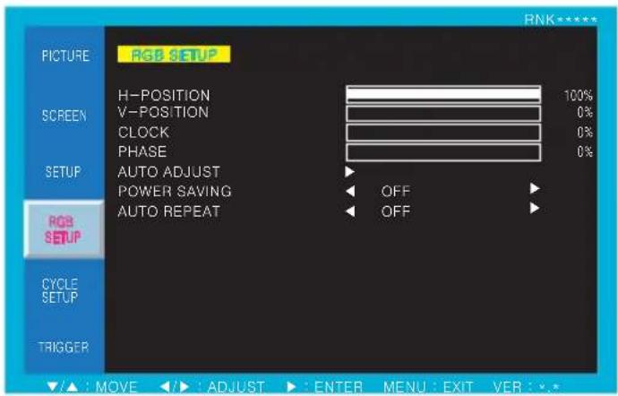
RGB SETUP (ONLY RGB PC MODE)
text_image
PICTURE RGB SETUP H-POSITION 100% SCREEN V-POSITION 0% CLOCK 0% PHASE 0% SETUP AUTO ADJUST POWER SAVING OFF AUTO REPEAT OFF RGB SETUP CYCLE SETUP TRIGGER ▲ : MOVE ▶ : ADJUST ▶ : ENTER MENU : EXIT VER : *.*- Press the MENU key to access menu.
- Use the ▲ or ▼ key to choose RGB SETUP.
- Press the ▶ key to enter the RGB SETUP menu.
- Use the ▲ or ▼ key to choose an item of RGB SETUP.
- Use the ◀ or ▶ key to adjust the setting on a selected item.
| ITEM FUNCTION | DEFAULT VALUE AVAILABLE MODE | ||
| H-POSITION Adjust the horizontal position of the screen RGB PC | |||
| V-POSITION Adjust the vertical position of the screen RGB PC | |||
| CLOCK Adjust the clock of the screen RGB PC | |||
| PHASE Adjust the phase of the screen RGB PC | |||
| AUTO ADJUST Adjust all of above items for suitable screen RGB PC | |||
| POWER SAVING | Adjust the power saving mode | OFF | RGB PC |
| AUTO REPEAT | Repeat AUTO ADJUST action automatically | OFF | RGB PC |
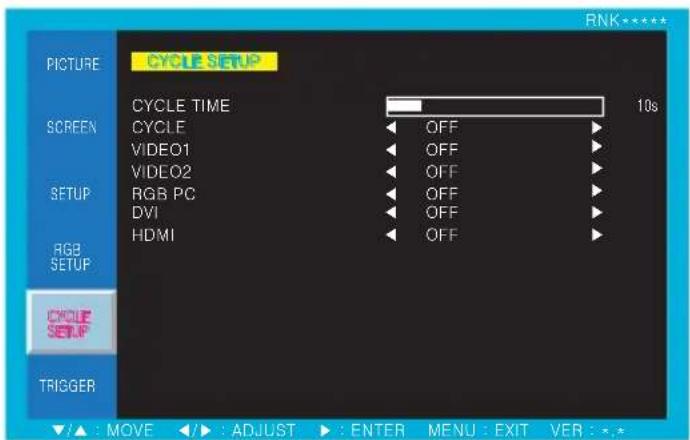
CYCLE SETUP
text_image
CYCLE SETUP PICTURE CYCLE TIME 10s SCREEN CYCLE OFF VIDEO1 OFF VIDEO2 OFF RGB PC OFF DVI OFF HDMI OFF RGB SETUP CYCLE SETUP TRIGGER ▲ : MOVE ▶ : ADJUST ▶ : ENTER MENU : EXIT VER : *.*- Press the MENU key to access menu.
- Use the ▲ or ▼ key to choose CYCLE SETUP.
- Press the ▶ key to enter the CYCLE SETUP menu.
- Use the ▲ or ▼ key to choose an item of CYCLE SETUP.
- Use the ◀ or ▶ key to adjust the setting on a selected item.
| ITEM FUNCTION | DEFAULT VALUE AVAILABLE MODE | ||
| CYCLE TIME Adjust the | time interval to display selected mode All modes | 10s (seconds) | |
| CYCLE | Display selected modes sequentially in set cycle time | OFF | All modes |
| VIDEO1 Choice as to whether to cycle of VIDEO1 mode All modes | OFF | ||
| VIDEO1 Choice as to whether to cycle of VIDEO2 mode All modes | OFF | ||
| RGB PC Choice as to whether to cycle of RGB PC mode All modes | OFF | ||
| DVI Choice as to whether to cycle of DVI mode All modesOFF | |||
| HDMI Choice as to whether to cycle of HDMI mode All modesOFF | |||
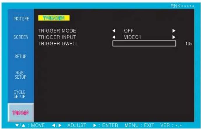
TRIGGER
text_image
PICTURE TRIGGER SCREEN TRIGGER MODE OFF TRIGGER INPUT VIDEO1 TRIGGER DWELL 10s SETUP RGB SETUP CYCLE SETUP TRIGGER ▲: MOVE ◀: ADJUST ▶: ENTER MENU: EXIT VER: *.*- Press the MENU key to access menu.
- Use the ▲ or ▼ key to choose TRIGGER.
- Press the ▶ key to enter the TRIGGER menu.
- Use the ▲ or ▼ key to choose an item of TRIGGER.
- Use the ◀ or ▶ key to adjust the setting on a selected item.
Notice :
After setting the trigger mode, if the trigger terminal is not closed(short input), the screen moves to Trigger modes.
Please set the trigger mode after connecting the trigger signal to the close position.
| ITEM FUNCTION | DEFAULT VALUE AVAILABLE MODE | ||
| TRIGGER MODE Set the trigger mode to OFF/FULL/PIP/DW1/DW2 All modes | OFF | ||
| TRIGGER INPUT | Select the input source of trigger mode (VIDEO1, VIDEO2) | VIDEO1 | All modes |
| TRIGGER DWELL | Set the transition time from trigger mode to normal mode | 10s (seconds) | All modes |
INPUT SIGNAL MODE TABLE
| INPUT SIGNAL MODE RESOLUTION VERTICAL FREQUENCY (Hz) | ||
| VGA / DVI | VGA 640X480 60 / 72 / 75 | |
| VGA 720X400 70 | ||
| SVGA 800X600 56 / 60 / 75 | ||
| XGA 1024X768 60 / 75 | ||
| SXGA- 1280X960 60 | ||
| SXGA 1280X1024 60 / 75 | ||
| WXGA 1366X768 60 | ||
| WXGA+ 1440X900 60 | ||
| FHD | 1920X1080 60 | |
| HDMI | SDTV 480i | 720X480 30 |
| SDTV 576i | 720X576 25 | |
| EDTV 480p | 720X480 60 | |
| EDTV 576p | 720X576 50 | |
| HDTV 720p | 1280X720 50 / 60 | |
| HDTV 1080i | 1920X1080 25 / 30 | |
| HDTV 1080p | 1920X1080 50 / 60 | |
5. FEATURE
| RNK42NHF | RNK42NNF | RNK46NHF | RNK46SHF | RNK55NHF | RNK82NNF | RNK46SNF | RNK55SHF | RNK55SNF | RNK70NNF | ||||
| Bezel Width | Outside to BEZEL | 13.4 mm | 13.4 mm | 15.5 mm | 5.7 mm (Two Sides) | 15.5 mm | 25.7 mm (TMB Sides) | 5.7 mm (Two Sides) | 5.7 mm (Two Sides) | 23.2 mm | |||
| Outside to Active Area | 15.2 mm | 15.2 mm | 17.5 mm | 5.9 mm (Two Sides) | 17.5 mm | 26.9 mm (Two Sides) | 5.9 mm (Two Sides) | 5.9 mm (Two Sides) | 26.5 mm | ||||
| Display | Screen Size | 42.0 inches | 42.0 inches | 46.0 inches | 46.0 inches | 54.6 inches | 48.0 inches | 54.6 inches | 54.6 inches | 70.0 inches | |||
| Resolution | 1920*1080 pixels | 1920*1080 pixels | 1920*1080 pixels | 1920*1080 pixels | 1920*1080 pixels | 1920*1080 pixels | 1920*1080 pixels | 1920*1080 pixels | 1920*1080 pixels | ||||
| Pixel Pitch | 0.485*0.485 mm | 0.485*0.485 mm | 0.530*0.530 mm | 0.530*0.530 mm | 0.530*0.530 mm | 0.530*0.530 mm | 0.630*0.630 mm | 0.630*0.630 mm | 0.607*0.607 mm | 0.941*0.941 mm | |||
| Brightness | 700 cd/m^2 | 450 cd/m^2 | 700 cd/m^2 | 700 cd/m^2 | 500 cd/m^2 | 700 cd/m^2 | 450 cd/m^2 | 700 cd/m^2 | 500 cd/m^2 | 400 cd/m^2 | |||
| Contrast Ratio | 1300:1 | 1300:1 | 3000:1 | 3500:1 | 3500:1 | 4000:1 | 3500:1 | 3500:1 | 3500:1 | 4000:1 | 5000:1 | ||
| Aspect Ratio | 16:9 | 16:9 | 16:9 | 16:9 | 16:9 | 16:9 | 16:9 | 16:9 | 16:9 | 16:9 | 16:9 | ||
| Viewing Angle (HV) | 178/178 degrees | 178/178 degrees | 178/178 degrees | 178/178 degrees | 178/178 degrees | 178/178 degrees | 178/178 degrees | 178/178 degrees | 178/178 degrees | 178/178 degrees | 178/178 degrees | ||
| Display Color | 16.7 million | 16.7 million | 16.7 million | 16.7 million | 16.7 million | 16.7 million | 16.7 million | 16.7 million | 16.7 million | ||||
| Response Time | 8 ms | 8 ms | 8 ms | 8 ms | 8 ms | 8 ms | 8 ms | 8 ms | 8 ms | 8 ms | 8 ms | ||
| Video System | NTSC/PAL | NTSC/PAL | NTSC/PAL | NTSC/PAL | NTSC/PAL | NTSC/PAL | NTSC/PAL | NTSC/PAL | NTSC/PAL | NTSC/PAL | NTSC/PAL | ||
| Panel Life Time | 50,000 hours | 50,000 hours | 50,000 hours | 50,000 hours | 50,000 hours | 50,000 hours | 50,000 hours | 50,000 hours | 50,000 hours | 50,000 hours | 50,000 hours | ||
| Interface | Video In/Out (BNC Type) | 2/2 | 2/2 | 2/2 | 2/2 | 2/2 | 2/2 | 2/2 | 2/2 | 2/2 | 2/2 | 2/2 | |
| VGA In/Out (15Pin D-Sub) | 1/1 | 1/1 | 1/1 | 1/1 | 1/1 | 1/1 | 1/1 | 1/1 | 1/1 | 1/1 | 1/1 | ||
| DVI In/Out | 1/1 | 1/1 | 1/1 | 1/1 | 1/1 | 1/1 | 1/1 | 1/1 | 1/1 | 1/1 | 1/1 | ||
| HDMI In/Out | 1/1 | 1/1 | 1/1 | 1/1 | 1/1 | 1/1 | 1/1 | 1/1 | 1/1 | 1/1 | 1/1 | ||
| RS-232 In/Out | 1/1 | 1/1 | 1/1 | 1/1 | 1/1 | 1/1 | 1/1 | 1/1 | 1/1 | 1/1 | 1/1 | ||
| Audio In (RCA Type) | 2 | 2 | 2 | 2 | 2 | 2 | 2 | 2 | 2 | 2 | 2 | ||
| PC Stereo In | 1 | 1 | 1 | 1 | 1 | 1 | 1 | 1 | 1 | 1 | 1 | ||
| Special Features | Built in Speakers | Y (10W^2) | Y (10W^2) | Y (10W^2) | Y (10W^2) | Y (10W^2) | Y (10W^2) | Y (10W^2) | Y (10W^2) | Y (10W^2) | Y (10W^2) | Y (10W^2) | |
| Remote Control | Y | Y | Y | Y | Y | Y | Y | Y | Y | Y | Y | ||
| RS-232 Control | Monitor OSD & Multi Vision | Monitor OSD & Multi Vision | Monitor OSD & Multi Vision | Monitor OSD & Multi Vision | Monitor OSD & Multi Vision | Monitor OSD & Multi Vision | Monitor OSD & Multi Vision | Monitor OSD & Multi Vision | Monitor OSD & Multi Vision | Monitor OSD & Multi Vision | Monitor OSD & Multi Vision | ||
| Multi Display Function | PIP/PBP | PIP/PBP | PIP/PBP | PIP/PBP | PIP/PBP | PIP/PBP | PIP/PBP | PIP/PBP | PIP/PBP | PIP/PBP | PIP/PBP | ||
| Filter Type | 3D Comb Filter | 3D Comb Filter | 3D Comb Filter | 3D Comb Filter | 3D Comb Filter | 3D Comb Filter | 3D Comb Filter | 3D Comb Filter | 3D Comb Filter | 3D Comb Filter | 3D Comb Filter | ||
| Deinterlacing | Y | Y | Y | Y | Y | Y | Y | Y | Y | Y | Y | ||
| Auto Pixel Shift | Y | Y | Y | Y | Y | Y | Y | Y | Y | Y | Y | ||
| FAN On/Off Control | N/A | N/A | Y | Y | Y | Y | Y | Y | Y | Y | Y | ||
| Temperature Sensor | N/A | N/A | Y | Y | Y | Y | Y | Y | Y | Y | Y | ||
| One Stretch Image by Edge Set | Y | Y | Y | Y | Y | Y | Y | Y | Y | Y | Y | ||
| Trigger Source Switching | Y | Y | Y | Y | Y | Y | Y | Y | Y | Y | Y | ||
| Noise reduction | Y | Y | Y | Y | Y | Y | Y | Y | Y | Y | Y | ||
| Auto source sequencing | Y | Y | Y | Y | Y | Y | Y | Y | Y | Y | Y | ||
| Multi Lingual Language | Eng Spa Fre, Ger, Ita | Eng Spa Fre, Ger, Ita | Eng Spa Fre, Ger, Ita | Eng Spa Fre, Ger, Ita | Eng Spa Fre, Ger, Ita | Eng Spa Fre, Ger, Ita | Eng Spa Fre, Ger, Ita | Eng Spa Fre, Ger, Ita | Eng Spa Fre, Ger, Ita | Eng Spa Fre, Ger, Ita | Eng Spa Fre, Ger, Ita | ||
| Dimension | Outline Dimension | 37.83*21.80*3.70 inches | 37.83*21.80*2.76 inches | 41.33*22.74*3.62 inches | 40.31*22.78*5.04 inches | 40.31*22.78*5.74 inches | 49.00*28.17*3.94 inches | 47.69*27.02*5.08 inches | 47.69*27.02*5.77 inches | 63.09*36.39*4.21 inches | 73.17*42.69*4.72 inches | ||
| 963.8553.794 mm | 963.8553.794 mm | 1049.86397 mm | 1023.98*578.57*128 mm | 1023.98*578.57*145.7 mm | 1244.9715.4*100 mm | 1215.9583.3*129 mm | 1215.9583.3*146.6 mm | 1602.4*924.4*107 mm | 1858.4*1084.4*126 mm | ||||
| Cabinet | Cabinet Color | Black | Black | Black | Black | Black | Black | Black | Black | Black | Black | Black | |
| Cabinet Material | Electro-Galvanized Steel | Electro-Galvanized Steel | Electro-Galvanized Steel | Electro-Galvanized Steel | Electro-Galvanized Steel | Electro-Galvanized Steel | Electro-Galvanized Steel | Electro-Galvanized Steel | Electro-Galvanized Steel | Electro-Galvanized Steel | Electro-Galvanized Steel | ||
| Regulations | CE, FCC | CE, FCC | CE, FCC | CE, FCC | CE, FCC | CE, FCC | CE, FCC | CE, FCC | CE, FCC | CE, FCC | CE, FCC | ||
| Power | Electrical Ratings | AC 100-240 V (50/80Hz) | AC 100-240 V (50/80Hz) | AC 100-240 V (50/80Hz) | AC 100-240 V (50/80Hz) | AC 100-240 V (50/80Hz) | AC 100-240 V (50/80Hz) | AC 1O0-240 V (50/80Hz) | AC 100-240 V (50/80Hz) | AC 100-240 V (50/80Hz) | AC 100-240 V (50/80Hz) | AC 100-240 V (50/80Hz) | |
| Circumstance | Operating Temperature | 0~40 celsius | 0~40 celsius | 0~40 celsius | 0~40 celsius | 0~40 celsius | 0~40 celsius | 0~40 celsius | 0~40 celsius | 0~40 celsius | 0~40 celsius | 0~40 celsius | |
| Storage Temperature | -20~65 celsius | -20~65 celsius | -20~65 celsius | -20~65 celsius | -20~65 celsius | -20~65 celsius | -20~65 celsius | -20~65 celsius | -20~65 celsius | -20~65 celsius | -20~65 celsius | ||
| Mounts | VESA Mounts Size | 600*300 mm | 600*300 mm | 600*400 mm | 600*400 mm | 600*400 mm | 600*400 mm | 600*400 mm | 600*400 mm | 600*400 mm | 800*600 mm | 800*600 mm | |
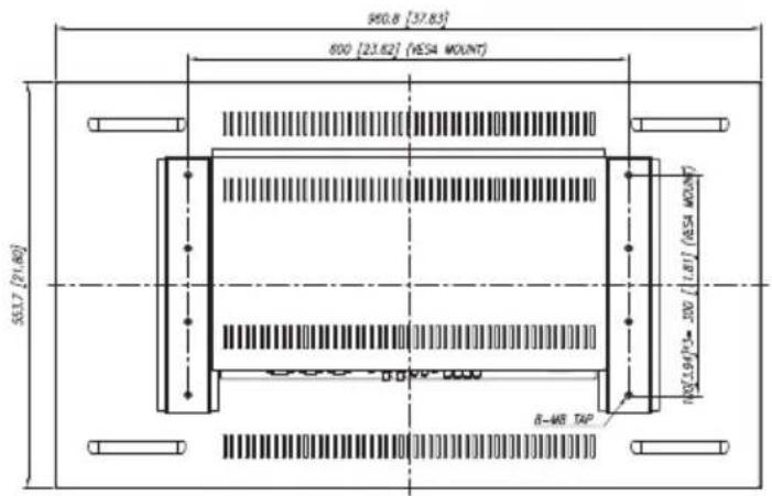
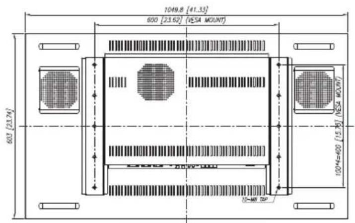
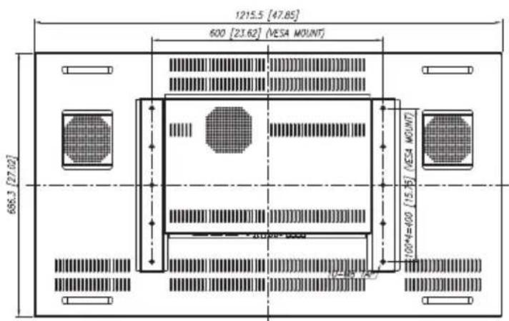
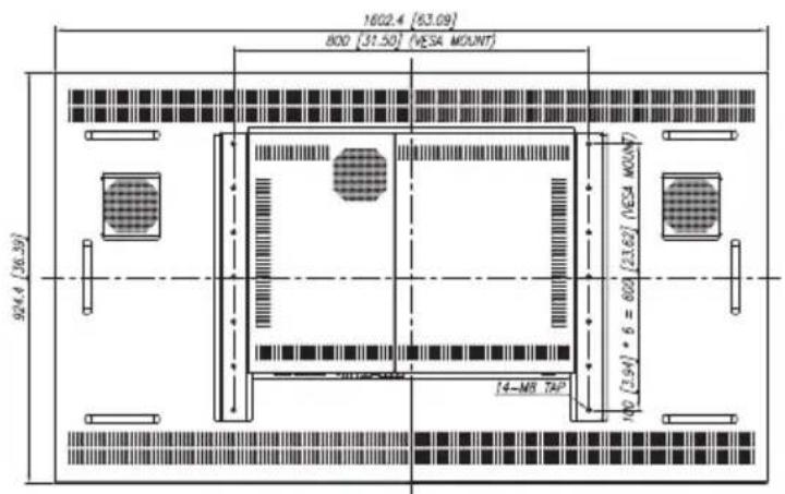
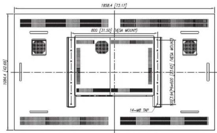
6. MECHANICAL DRAWING
Units : mm [inches]
text_image
960.8 [37.83] 800 [23.82] (YESA MOUNT) 55.17 [71.80] 8-48 TAP NO[1.94]×10^-100RNK42NHF / NNF
text_image
1049.8 [41.33] 600 [23.62] (VESA MOUNT) 603 [23.74] 100*4=400 [15.75] (VESA MOUNT) 10-MT DIPRNK46NHF RNK46

text_image
1023.98 [40.31] 600 [23.62] (VESA MOUNT) 578.57 [22.78] 100[1.94]N=400 [10.75] (VESA MOUNT) 10-40° 50°

text_image
1244.6 [49.00] 500 [23.62] (ESA MOUNT) 715.4 [28.17] 10/1(1.94)*4=400 (18.75) (ESA MOUNT)RNK55NHF RNK55
text_image
1215.5 [47.85] 600 [23.62] (VESA MOUNT) 686.3 [27.02] 100*4=400 (15.75) (VESA MOUNT)
text_image
1602.4 (63.09) 800 [31.50] (VESA MOUNT) 924.4 (36.39) [23.62] (VESA MOUNT) 14-M8 TAIP 180 [3.94] * 6 = 600
text_image
1858.4 [73.17] 800 [31.50] VESA MOUNT 1064.4 (42.69) 100 [194/96=600 (31.62) VESA MOUNT 14-M8 TAP
7. TROUBLESHOOTING
* When the following troubles are occurred, follow the trouble shooting. Before contacting a service center.
| Troubleshooting | Troubleshooting Tip |
| The screen doesn't show up | 1. Make sure if the power supply is connected property |
| 2. Turn on the power. | |
| 3. Select the input signal right for the connected port. | |
| The screen is too light or to dark | Control the BRIGHTNESS |
| The screen size is not fit for the PC signal | Press the AUTO key among keys in the front.(It is used only in the PC signal) |
| The screen color shows strange in the PC signal | In the FUNCTION menu of OSD menu, perform the AUTOADJUST. |