Benchmark-Dual-HH - Karaoke Vocopro - Free user manual and instructions
Find the device manual for free Benchmark-Dual-HH Vocopro in PDF.

User questions about Benchmark-Dual-HH Vocopro
0 question about this device. Answer the ones you know or ask your own.
Ask a new question about this device
Download the instructions for your Karaoke in PDF format for free! Find your manual Benchmark-Dual-HH - Vocopro and take your electronic device back in hand. On this page are published all the documents necessary for the use of your device. Benchmark-Dual-HH by Vocopro.
USER MANUAL Benchmark-Dual-HH Vocopro
Trusted by Professionals Since 1991

natural_image
Line drawing of a multi-wire electronic device with two front-mounted speakers and two microphones, no text or symbols present.Benchmark
Touring Grade Diversity Wireless System with Antenna Distribution System and Active Directional Antennas
OWNER'S MANUAL
And thank you for purchasing Benchmark from VocoPro. Along with quality products our commitment to customer satisfaction means we have technical support professionals ready to assist you. Be sure to visit our website-www.vocopro.com for the latest information on new products.
We are at:
VocoPro
1728 Curtiss Court
La Verne, CA 91750

Phone:
Toll Free: 800-678-5348
TEL: 909-593-8893
FAX: 909-593-8890

Tech Support:
techsupport@vocopro.com
Customer Service:
info@vocopro.com
Legal Disclaimer
All rights reserved. Information, specifications, diagrams, images, and instructions herein are subject to change without notice. VocoPro Products, logo and identifying product names and numbers herein are trademarks of VocoPro. Copyright protection claimed includes all forms and matters of copyrightable materials and information now allowed by statutory or judicial law or hereinafter granted. Product names used in this document may be trademarks or registered trademarks of their respective companies and are hereby acknowledged. All non-VocoPro Products, brands and product names are trademarks or registered trademarks of their respective companies.
VocoPro hereby disclaims any and all liabilities for property, equipment, building, and electrical damages, injuries to any persons, and direct or indirect economic loss associated with the use or reliance of any information contained within this document, and/or as a result of the improper, unsafe, insufficient and negligent assembly, installation, rigging, and operation of this product.
Please record the model number and serial number below, for easy reference, in case of loss or theft. These numbers are located on the packaging the item came in. Space is also provided for other relevant information.
This is not considered a receipt. Please keep a copy of your purchase receipt, provided by the dealer, in your records. A receipt is required for all warranty work.
Model Number
Serial Number
Date of Purchase
Place of Purchase
Selecting fine audio equipment such as the unit you've just purchased is only the start of your musical enjoyment. Now it's time to consider how you can maximize the fun and excitement your equipment offers. VocoPro and the Electronic Industries Association's Consumer Electronics Group want you to get the most out of your equipment by playing it at a safe level. One that lets the sound come through loud and clear without annoying blaring or distortion and, most importantly, without affecting your sensitive hearing.
Sound can be deceiving. Over time your hearing "comfort level" adapts to a higher volume of sound. So what sounds "normal" can actually be loud and harmful to your hearing. Guard against this by setting your equipment at a safe level BEFORE your hearing adapts.
To establish a safe level:
- Start your volume control at a low setting.
- Slowly increase the sound until you can hear it comfortably and clearly, and without distortion.
Once you have established a comfortable sound level:
- Set the dial and leave it there.
- Pay attention to the different levels in various recordings.
Taking a minute to do this now will help to prevent hearing damage or loss in the future. After all, we want you listening for a lifetime.
Used wisely, your new sound equipment will provide a lifetime of fun and enjoyment. Since hearing damage from loud noise is often undetectable until it is too late, this manufacturer and the Electronic Industries Association's Consumer Electronics Group recommend you avoid prolonged exposure to excessive noise. This list of sound levels is included for your protection.
Level Example
30 Quiet library, Soft whispers
40 Living room, Refrigerator, Bedroom away from traffic
50 Light traffic, Normal Conversation
60 Air Conditioner at 20 ft., Sewing machine
70 Vacuum cleaner, Hair dryer, Noisy Restaurant
80 Average city traffic, Garbage disposals, Alarm clock at 2 ft.
The following noises can be dangerous under constant exposure:
Level Example
90 Subway, Motorcycle, Truck traffic, Lawn Mower
100 Garbage truck, Chainsaw, Pneumatics drill
120 Rock band concert in front of speakers
140 Gunshot blast, Jet plane
180 Rocket launching pad
-Information courtesy of the Deafness Research Foundation
CAUTION
RISK OF SHOCK

CAUTION: To reduce the risk of electric shock, do not remove cover (or back). No user-serviceable parts inside. Only refer servicing to qualified service personnel.
Explanation of Graphical Symbols

The lightning flash & arrowhead symbol, within an equilateral triangle, is intended to alert you to the presence of danger.

The exclamation point within an equilateral triangle is intended to alert you to the presence of important operating and servicing instructions.
WARNING: To reduce the risk of fire or electric shock, do not expose this unit to rain or moisture.
- Read Instructions - All the safety and operating instructions should be read before the appliance is operated.
- Retain Instructions - The safety and operating instructions should be retained for future reference.
- Heed Warnings - All warnings on the appliance and in the operating instructions should be adhered to.
-
Follow Instructions - All operating and use instructions should be followed.
-
Attachments - Do not use attachments not recommended by the product manufacturer as they may cause hazards.
-
Water and Moisture - Do not use this unit near water. For example, near a bathtub or in a wet basement and the like.
-
Carts and Stands - The appliance should be used only with a cart or stand that is recommended by the manufacturer.
7 A. An appliance and cart combination should be moved with care. Quick stops, excessive force, and uneven surfaces may cause an overturn.
- Ventilation - The appliance should be situated so its location does not interfere with its proper ventilation. For example, the appliance should not be situated on a bed, sofa, rug, or similar surface that may block the ventilation slots.

-
Heat - The appliance should be situated away from heat sources such as radiators, heat registers, stoves, or other appliances (including amplifiers) that produce heat.
-
Power Sources - The appliance should be connected to a power supply only of the type described in the operating instructions or as marked on the appliance.
-
Grounding or Polarization - Precautions should be taken so that the grounding or polarization means of an appliance is not defeated.
-
Power-Cord Protection - Power-supply cords should be routed so that they are not likely to be walked on or pinched by items placed upon or against them, paying particular attention to cords at plugs, convenience receptacles, and the point where they exit from the appliance.
-
Cleaning - Unplug this unit from the wall outlet before cleaning. Do not use liquid cleaners or aerosol cleaners. Use a damp cloth for cleaning.
-
Power lines - An outdoor antenna should be located away from power lines.
-
Non-use Periods - The power cord of the appliance should be unplugged from the outlet when left unused for a long period of time.
-
Object and Liquid Entry - Care should be taken so that objects do not fall and liquids are not spilled into the enclosure through openings.
-
Damage Requiring Service - The appliance should be serviced by qualified service personnel when:
A. The power supply cord or plug has been damaged; or
B. Objects have fallen into the appliance; or
C. The appliance has been exposed to rain; or
D. The appliance does not appear to operate normally or exhibits a marked change in performance; or
E. The appliance has been dropped, or the enclosure damaged.
- Servicing - The user should not attempt to service the appliance beyond that described in the operating instructions. All other servicing should be referred to qualified service personnel.
Note: To CATV system installer's (U.S.A.): This reminder is provided to call the CATV system installer's attention to Article 820-40 of the NEC that provides guidelines for proper grounding and, in particular, specifies that the cable ground shall be connected as close to the point of cable entry as practical.

This device complies with Part 15 of the FCC rules. Operation is subject to the condition that this device may not cause harmful interference.
FCC license may be required
-
IMPORTANT NOTICE: DO NOT MODIFY THIS UNIT!: This product, when installed as indicated in the instructions contained in this manual, meets FCC requirements. Modifications not expressly approved by Vocopro may void your authority, granted by the FCC, to use this product.
-
IMPORTANT: When connecting this product to accessories and/or another product use only high quality shielded cables. Cable(s) supplied with this product MUST be used. Follow all installation instructions. Failure to follow instructions could void your FCC authorization to use this product in the U.S.A.
-
NOTE: This product has been tested and found to comply with the requirements listed in FCC Regulations, Part 15 for Class "B" digital devices. Compliance with these requirements provides a reasonable level of assurances that your use of this product in a residential environment will not result in harmful interference with other electronic devices. This equipment generates/uses radio frequencies and, if not installed and used according to the instructions found in the owner's manual, may cause interference harmful to the operation of other electronic devices. Compliance with FCC regulations does not guarantee that interference will not occur in all installations. If this product is found to be the source of interference, which can be determined by turning the unit "Off" and "On", please try to eliminate the problem by using one of the following measures:
Relocate either this product or the device that is being affected by the interference.
Use power outlets that are on different branch (circuit breaker or fuse) circuits or install AC line filter(s).
In the case of radio or TV interference, relocate/reorient the antenna. If the antenna lead-in is 300-ohm ribbon lead, change the lead-in to coaxial type cable.
If these corrective measures do not produce satisfactory results, please contact your local retailer authorized to distribute Vocopro products. If you can not locate the appropriate retailer, please contact Vocopro, 1728 Curtiss Court, La Verne, CA 91750.
CAUTION: READ THIS BEFORE OPERATING YOUR UNIT
-
To ensure the finest performance, please read this manual carefully. Keep it in a safe place for future reference.
-
Install your unit in a cool, dry, clean place - away from windows, heat sources, and too much vibration, dust, moisture or cold. Avoid sources of hum (transformers,
CALIFORNIA PROP 65 WARNING
WARNING: Cables, Cable Assemblies, and Printed Circuit Boards can expose you to chemicals including lead and lead compounds which are known to the State of California to cause cancer and birth defects or other reproductive harm. For more information, go to www.P65Warnings.ca.gov
electric motors). To prevent fire or electrical shock, do not expose to rain and water.
- Do not operate the unit upside-down.
- Never open the cabinet. If a foreign object drops into the set, contact your dealer.
- Place the unit in a location with adequate air circulation. Do not interfere with its proper ventilation; this will cause the internal temperature to rise and may result in a failure.
- Do not use force on switches, knobs or cords. When moving the unit, first turn the unit off. Then gently disconnect the power plug and the cords connecting to other equipment. Never pull the cord itself.
- Do not attempt to clean the unit with chemical solvents: this might damage the finish. Use a clean, dry cloth.
- Be sure to read the "Troubleshooting" section on common operating errors before concluding that your unit is faulty.
- This unit consumes a fair amount of power even when the power switch is turned off. We recommend that you unplug the power cord from the wall outlet if the unit is not going to be used for a long time. This will save electricity and help prevent fire hazards. To disconnect the cord, pull it out by grasping the plug. Never pull the cord itself.
- To prevent lightning damage, pull out the power cord and remove the antenna cable during an electrical storm.
- The general digital signals may interfere with other equipment such as tuners or receivers. Move the system farther away from such equipment if interference is observed.
NOTE: Please check the copyright laws in your country before recording from records, compact discs, radio, etc. Recording of copyrighted material may infringe copyright laws.
Voltage Selector (General Model Only)
Be sure to position the voltage selector to match the voltage of your local power lines before installing the unit.

CAUTION: The apparatus is not disconnected from the AC power source so long as it is connected to the wall outlet, even if the apparatus itself is turned off. To fully ensure that the apparatus is indeed fully void of residual power, leave unit disconnected from the AC outlet for at least fifteen seconds.
text_image
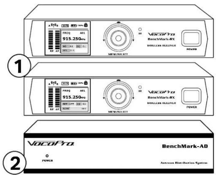
A B D FREQ A01 915.250Hz NO 01 SQ 01 RF AF VocoPro BenchMark-RX WHILLLES HILLIVLR MENUSSELET POWER VocoPro BenchMark-RX WHILLLES HILLIVLR MENUSSELET POWER VocoPro BenchMark-AD POWER Antenna Distribution System
text_image
VacoPro VacoPro 3- Receivers
- Antenna Distributor
- Active Directional Antenna
- Beltpack Transmitter
*Depends on Package (Benchmark-Dual/Quad-BP only)
5. HandheldTransmitter
*Depends on Package (Benchmark-Dual/Quad-HH only)
6. Headset Microphone
*Depends on Package (Benchmark-Dual/Quad-BP only)
7. Lavelier Microphone
*Depends on Package (Benchmark-Dual/Quad-BP only)
8. 1 14 Cable
9. BNC Connector Cable
10. Power Cable
11. Power Adapter
12. Long Rack Mount
13. Short Rack Mount
14. Connect Panel
15. Ring Adapter
16. BM-36 Stand

natural_image
Line drawing of a portable electronic device with antenna and control buttons (no text or symbols)*Depends on Package

natural_image
Line drawing of a wireless microphone with no text or symbols on the device itself*Depends on Package

text_image
8 9 10 6 *Depends on Package 7 *Depends on Package 11 12 13 14
text_image
mount mount el 16Features
- Touring grade true diversity wireless microphone system.
- 600ft. range (line of sight) when used with antenna distribution system and active directional antennas.
- Operates in 900MHz band, away from TV, radio, and Wifi interference.
• Color display shows frequency, reception, and battery status. - Scan feature with graphic display shows RF traffic within range.
- Multiple options for wireless synchronization: via infrared syncing, group and channel select, or frequency select.
- Tour-ready rugged metal housing for handheld and belt pack transmitters.
- Antenna distributor will supply power to up to 4 receivers and 2 active antennas
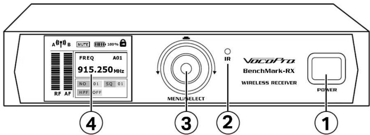
Receiver Front
text_image
A (↑↑) B MUTE 100% FREQ A01 915.250 MHz NO 01 SQ 01 HPF OFF RF AF VocoPro BenchMark-RX WIRELESS RECEIVER IR MENU/SELECT 2 POWER 4 3 1- Power Button- Hold button to turn the receiver on and off. Press once to exit the menu.
- IR Sync Indicator Light- Will be light when performing IR Sync.
- Menu/Select Knob- Turn to change selection and press to confirm setting.
- Color Display- Shows microphone information and menu options.
Receiver Rear View
text_image
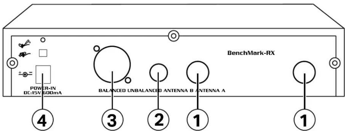
BenchMark-RX POWER-IN DC:15V 600mA BALANCED UNBALANCED ANTENNA B ANTENNA A ④ ③ ② ① ①- Antenna A/B BNC Connector Socket
- 14 inch Unbalanced Audio Output
- XLR Balanced Output
- 12V-15V DC Power Input
a. (Please note you do not need to connect the receiver to power if you are using the Antenna Distribution system, it will supply power to the receivers.)
Receiver Main Screen
- Anetnna Connection Status - Shows which antenna has a stronger connection from the transmitter.
- Mute - Will display if the transmitter is muted.
- Battery Indicator - Shows the current battery life of the transmitter.
- Group/Channel Indicator - Displays the current group and channel selected. If the frequency was selected manually using the Frequency option or Scan option, nothing will be displayed.
- Frequency - Displays the MHz frequency that the receiver is set to look for.
- RF Indicator - Displays connection strength between the transmitter and receiver
- AF Indicator - Displays the audio level being picked up by the mic.
- NO - Shows the number set for the transmitter.
- SQ - Shows squelch setting.
- HPF - Shows if the Low Cut Filter (High Pass Filter) is on or off.
- Lock - This icon will appear when the transmitter or receiver has been locked to prevent any settings changes.

text_image
① A ( ) B MUTE 100% ② ③ ⑪ FREQ A01 915.250 MHz RF AF HPF OFF SQ 01 NAME 001 ④ ⑤ ⑨ ⑥ ⑦ ⑧ ⑩Receiver Menu Options
text_image
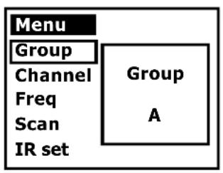
Menu Group Channel Freq Scan IR set Group A
text_image
Menu Number Squelch Lock Low Cut ← Back ← Back- Group - Change the frequency group. Groups are lettered A-J. Channels in the same group letter are designed to work together without interference.
- Channel - Change the channel within a group. Channels are numbered 1-10.
- Freq - Manually select the MHz frequency. Frequencies can be changed in increments of .025Mhz.
- Scan - Begin scanning for nearby RF signals. The scan takes about 1 minute, to stop scanning early, press the power button. After the scan is complete, use the knob to select an open frequency.
- IR Set - This will begin the syncing process to pair a transmitter with the receiver. Hold the transmitter so the IR sensor is directly in front of the IR Sync Light on the receiver before you begin. The IR Light on the receiver will light up when it is pairing, and go out when the process is complete. The transmitter will now display the new frequency set by the receiver.
- Number - Change the number displayed on the transmitter. Numbers go from 01-99. This has no effect on frequency, it is simply for easy identification.
- Squelch - Change the squelch setting, 1-10. Squelch will cut the volume if the transmitter connection is poor or if the volume is low. But it can also be used to set a maximum distance for your mics so you do not pick up unwanted signals.
**For general use, it is recommended to leave the squelch setting at 1, and if you are experiencing interference issues, try changing the frequency first.
Press the Menu/Select knob once to access the menu. Turn the knob to highlight the option you want. Press the knob again to access that option.
- Lock - Turn on to lock the receiver to not allow any changes to settings. Hold down the Menu/Select button for a few seconds to unlock the receiver.
- Low Cut - Turn on or off the low cut filter. This will cut out the lowest audio frequencies picked up by the mic, this will help reduce rumble and stage noise. It will be displayed on the main screen as HPF (high pass filter). Low cut and high pass mean the same thing.
- Back - Return to the main screen. Pressing the power button will also return to the main screen. The system will also return to the main screen if there are no inputs after about 15 seconds.
- Low Voltage - When the batteries in the transmitter are low and need to be changed, the receiver will display Low Voltage in red.
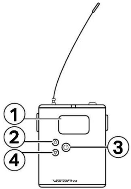
Handheld Microphone Transmitter
- OLED Display - Shows mic number, mic information, and menu options.
- Power Button - Hold to turn mic on and off. Press to display mic info. Press again to mute or unmute the mic.
- Up - Press to move menu selection up
- ▽Down - Press to move menu selection down
- Select - Press to enter menu, to select menu option, and to confirm selection.
- IR Sensor - Receives IR signal from the receiver during syncing.
Handheld Microphone Transmitter Menu Options:
Press the ● select button to enter the menu. Use arrow buttons to select the desired option. Press the select button to enter and exit the selection.
- Group - Change the frequency group. Groups are lettered A-J. Channels in the same group letter are designed to work together without interference.
- Channel - Change the channel within a group. Channels are numbered 1-10.
- Freq - Manually select the MHz frequency. Frequencies can be changed in increments of .025Mhz.
- Gain - Change gain setting for the mic. Gain can be set from +0dB up to +10dB in increments of 1dB.
- Lock - Set to ON to not allow changes to the handheld settings. Hold the select button for a few seconds to unlock the mic.
- Back - Return to the main screen. Pressing the power button will also return to the main screen. The mic will also return to the main screen if there are no inputs after about 15 seconds.

text_image
VacoPVD BenchMark-4T ① ② ③ ④ ⑤ ⑥ IRBelt Pack Transmitter
text_image
① ② ③ ④ VAC/Pyn-
OLED Display - Shows mic number, mic information, and menu options.
-
△ - Press to move selection up.
-
Ⓞ - Hold to turn the pack on and off. Press to cycle through menu options.
-
△ - Press to move selection down.
-
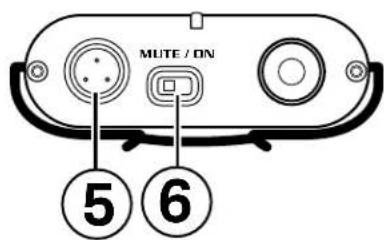
Mini-XLR Input - Input connection for the headset or lavaliere mic.
-
Mute/On Switch - Set to mute to silence the pack. The power light will be yellow when in mute.
-
IR Sensor - Receives IR signal from the receiver during syncing.
-
Lock/Unlock - Set to Lock to not allow changes to the pack settings.
-
Battery Compartment - Holds two AA batteries. Outside battery should be positive side out, inside battery should be negative side out.
text_image
MUTE / ON ⑤ ⑥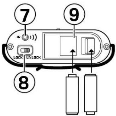
text_image
7 IR 9 LOCK UNLOCK 8 BBelt Pack Transmitter Menu Options:
Press the Power button to cycle through the two menu options.
FREQ - Manually select the MHz frequency. Frequencies can be changed in increments of .025Mhz.
GAIN - Change gain for the pack. Gain can be set to +10dB, +0db, or -10dB.
Antenna Distributor Rear View
-
A1-A4 BNC Connectors - These connections are used to connect to the Antenna A sockets on the receivers.
-
RF Out A - This is used only if you are connecting multiple Antenna Distribution systems.
-
Antenna RF In A - Antenna A input.
-
Antenna RF In B - Antenna B input.
-
RF Out B - This is used only if you are connecting multiple Antenna Distribution systems.
-
B1-B4 BNC Connectors - These connections are used to connect to the Antenna B sockets on the receivers.
-
DC Power In - Connect the power cable here.

text_image
1 2 3 4 5 6 7Wiring Diagram for Connecting Receivers to the Antenna Dltributor

flowchart
graph TD
    subgraph VocoPro
        A["Component a"] -->|f| B["Component b"]
        C["Component c"] -->|e| D["Component d"]
        E["Component d"] -->|e| F["Component e"]
    end
    G["Component g"] -->|f| H["Component h"]
    I["Component h"] -->|e| J["Component i"]
    K["Component j"] -->|e| L["Component j"]
    M["Component k"] -->|f| N["Component l"]
    O["Component l"] -->|e| P["Component m"]
    Q["Component m"] -->|e| R["Component n"]
    S["Component n"] -->|e| T["Component o"]
    U["Component o"] -->|e| V["Component p"]
    W["Component w"] -->|e| X["Component q"]
    Y["Component y"] -->|e| Z["Component r"]
    AA["Component x"] -->|e| AB["Component v"]
    AC["Component w"] -->|e| AD["Component y"]
    AE["Component x"] -->|e| AF["Component y"]
• To connect the Receivers to the Antenna Distribution system, follow the diagram above.
- Use the BNC cables to connect from the Antenna A sockets on each receiver to the A1 A2 A3 and A4 sockets on the top row of the Distributor. Connect from the Antenna B sockets on each receiver to the B1 B2 B3 and B4 sockets on the Distributor.
- Connect from the Antenna RF in A and Antenna RF in B to each of the Directional Antenna.
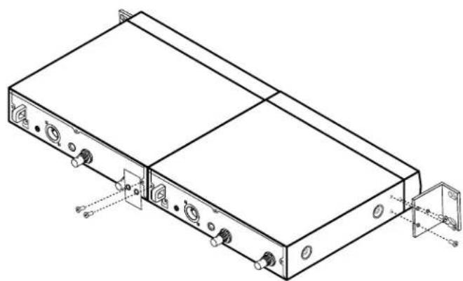
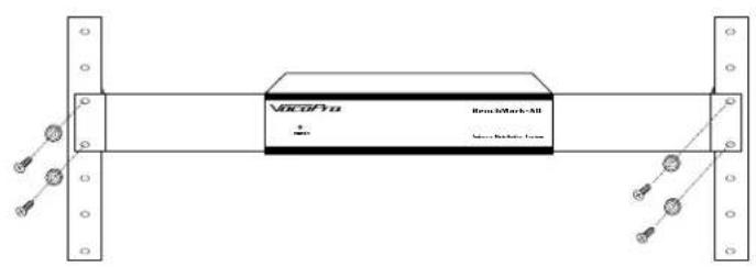
Installing the Receivers and Antenna Distributor into the Flight Case

natural_image
Diagram of a mechanical device with labeled components and directional arrows indicating assembly or movement (no text or symbols present)- To install the receivers into the included flight case, you will first need to remove the feet from the receiver.
- Next, use the connector plate and two screws to secure two of the receivers together.
- Then, secure the rack ears to the outside edges of the receivers, using two screws for each ear.
- And finally, insert the receivers into the case and use two screws on each side to secure it into the case.
natural_image
Technical line drawing of a rectangular electronic device with mounting ports and connectors (no text or symbols)
text_image
Diagram of a rack-mounted server unit with labeled ports and connectors, showing front panel and side panels with status indicators.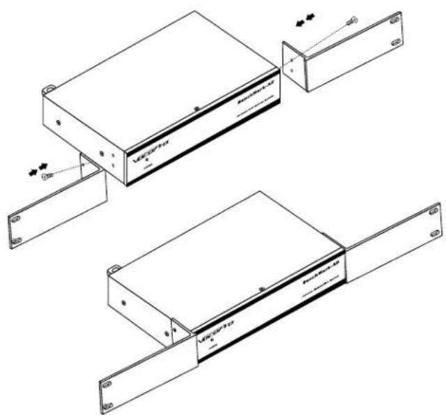
natural_image
Technical line drawing of two electronic device modules with mounting brackets and connectors (no text or symbols)- To install the Antenna Distributor into the flight case, first secure the long rack ears to the Distributor. Then connect the ears to the flight case and secure using two screws on each side.
text_image
VACOPa Rosc & Marks All + - MOS Sonic Radiator FluxSystem
Operating range: 600 ft. line of sight
AF response: 20Hz - 18KHz
T.H.D.: <1% (@AF1 KHz, RF46 dBu)
Dynamic range >100dB
S/N ratio: >90dB
Pilot Frequency: 32.768KHz
Receiver
AF output level: Unbalanced +9dBu/ Balanced +9dBu
AF output impedance: Unbalanced 810 Ohms/ Balanced
240 Ohms
Sensitivity: -100dBm/ 30dB sinad
Operation voltage: 12V-15V
Transmitter (Handheld)
Microphone type: Dynamic
Output gain range: 10dB (0dB -- +10dB)
RF output power: 10mw/ 30mw optional
Operation voltage: 2x 1.5V AA battery
Operation time: 8-10 hours
Transmitter (Bodypack)
Input: Mini XLR (TA3F)
Input impedance: 1M Ohms
Output gain range: 20dB (-10dB -- +10dB)
RF output power: 10mw/30mw optional
Operation voltage: 2x 1.5V AA battery
Operation time: 8-10 hours
Antenna Distributor
Input type: BNC Coaxial
Frequency range: 470-980MHz (-3dB)
RF out A: 0±1dB
A1 to A4: 0±1dB
B1 to B4: 0±1dB
Impedance: 50 Ohms
Reflection loss: 10dB (all high frequency output)
Operation voltage: 12V DC
Unit power consumption: 200mA
Total power consumption: Max 2.0A (4 receiver + 2 antenna)
Antenna RF in A and Antenna RF in B: 12V, 500mA
A1 to A4 power to receiver: 12V, 500mA
The Antenna Distributor is not powering on.
Check to see that the power adapter is getting power. The blue light on the adapter will indicate it is getting power. If there is no blue light, try plugging into another outlet. Also ensure the adapter is securely connected to the DC IN on the Distributor unit.
The Receivers are not powering on with the Antenna Distributor.
Ensure the Distributor is correctly connected to the receivers. The Antenna A socket on the receiver should be connected to one of the A1 through A4 sockets on the Distributor.
The Transmitter is not powering on.
Make sure you use a fresh pair of AA batteries, and that they are installed correctly into the transmitter with positive and negative ends.
Transmitter is on but there is no RF signal on the receiver.
Make sure the Receivers are correctly and completely connected to the Antenna Distributor. Also make sure the Directional Antenna are connected and pointing towards the performance area.
In order for the receiver to receive signal from the transmitter they must be set to the exact same frequency. Please see Pairing the Microphones below.
The Transmitter is connected but there is no AF signal.
Ensure the transmitter is not on MUTE. This is indicated on the receiver as well as the handheld mic display and the light on the beltpack.
RF and AF signal is good, but I have no audio to the board.
Each receiver must be connected separately to the mixer, with either a XLR cable to the balanced output, or a 14 inch cable to the unbalanced output. If the problem persists, try another audio cable.
Pairing the Microphones
In order for the receiver to receive signal from the transmitter they must be set to the exact same frequency. There are a few ways to make that happen, using functions described on pages 10-12.
Step 1: Set the frequency on the Receiver first. This can be 3 different ways.
Option 1 - Use the Scan function to find an open frequency and select it.
Option 2 - Use the Group and Channel options to set. Ex: Group A Channel 02.
Option 3 - Use the frequency option to set a specific frequency.
Step 2: Set the frequency on the Transmitter. This can also be done 3 different ways.
Option 1 - Select IR Set on the receiver. When the display shows IR Set and the red IR light is on, you must be holding the transmitter within 2 feet of the receiver, and have the IR sensor on the transmitter pointing directly at the red IR light.
Option 2 - Set the Group and Channel on the Handheld Mic. Using the arrows and select button on the mic, set the group and channel to same values that were set on the Receiver. This is not available on the Beltpack Transmitter.
Option 3 - Use the FREQ option to set the specific frequency and match it to the Receiver.
Notes
Our Team is Here to Help


Please do not return to the retailer if you are having a technical issue operating or connecting the unit. If you need additional help, have questions, or need support with your VocoPro product contact us:
Toll Free: 800-678-5348
TEL: 909-593-8893
FAX: 909-593-8890
Email Tech Support at:
techsupport@vocopro.com