NS27 - Speaker NavAtlas - Free user manual and instructions
Find the device manual for free NS27 NavAtlas in PDF.

User questions about NS27 NavAtlas
0 question about this device. Answer the ones you know or ask your own.
Ask a new question about this device
Download the instructions for your Speaker in PDF format for free! Find your manual NS27 - NavAtlas and take your electronic device back in hand. On this page are published all the documents necessary for the use of your device. NS27 by NavAtlas.
USER MANUAL NS27 NavAtlas
natural_image
Three black perforated industrial heat exchangers with mounting brackets, no visible text or symbolsNS14A/NS27A/NS35A
INSTALLATION/OWNER'S MANUAL
NavAtlas™
Preparation/Installation
Please read entire manual before installation.
Before You Start
- Disconnect negative battery terminal. Consult a qualified technician for instructions.
- Use extreme caution when drilling holes to avoid damaging fuel lines, hydraulic lines or existing wiring.
- If additional wiring is required, we recommend that you run all wires prior to mounting your speaker in place.
- Use the highest quality connectors for a reliable installation and to minimize signal and power loss.
- Avoid running wires over, near, or through sharp edged surfaces. We suggest you also use rubber grommets to protect any wires routed through metal.
Mounting and Installation
- Determine where the sound bar will be mounted. Ensure an area large enough for the sound bar to mount evenly.

text_image
the sound bar to mount evenly.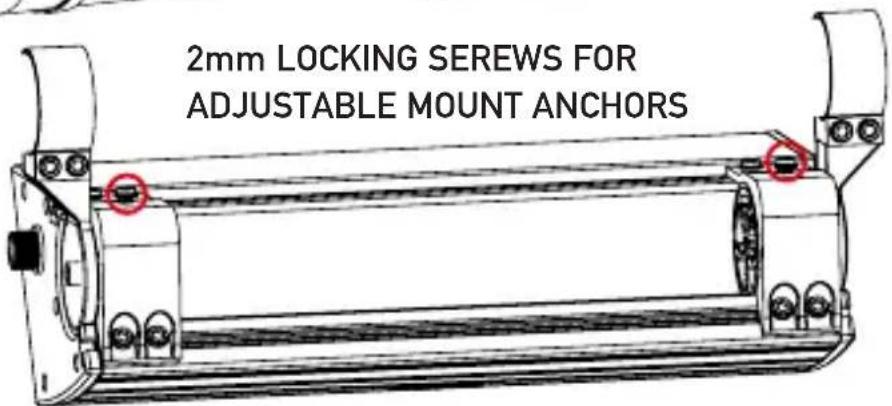
text_image
2mm LOCKING SEREWS FOR ADJUSTABLE MOUNT ANCHORSPreparation/Installation
Please read entire manual before installation.
Before You Start
- Disconnect negative battery terminal. Consult a qualified technician for instructions.
- Use extreme caution when drilling holes to avoid damaging fuel lines, hydraulic lines or existing wiring.
- If additional wiring is required, we recommend that you run all wires prior to mounting your speaker in place.
- Use the highest quality connectors for a reliable installation and to minimize signal and power loss.
- Avoid running wires over, near, or through sharp edged surfaces. We suggest you also use rubber grommets to protect any wires routed through metal.
Mounting and Installation
- Determine where the sound bar will be mounted. Ensure an area large enough for the sound bar to mount evenly.
Part List
| 8x 5mm x 12mm Allen screws (Flush Mount Anchors) | 2X Adjustable Brackets |
| 8x 5mm x 15mm Allen screws (Adjustable Brackets) | 2X Adjustable Anchors |
| 2x 5mm x 15mm Allen screws (Adjustable Anchors) | 2X 1.5" Bar Clamps |
| 2x 2mm Allen screws (Adjustable Anchor Lock) | 2X 1.75" Bar Clamps |
| 2X Flush Mount Clamps | 2X 2" Bar Clamps |
| 4X Flush Mount Anchors | 1 X Fuse Holder |
| Gaskets(Bar Mount & Flush Mount) | 1 X Allen Tool |

text_image
ADJUSTABLE BRACKET *2 ADJUSTABLE ANCHOR *2 ANCHOR*4 FLUSH MOUNT GASKETS*2 1.5' TOP GASKETS *2 1.75' TOP GASKETS *2 M6x15*10 M6x12*8 M6x12*2 Allen Wrench *1 1.5' BOTTOM GASKETS *4 1.75' BOTTOM GASKETS *4 2' TOP GASKETS *2 CLAMP GASKET *4 Fuse Holder(15A) *1 FLUSH MOUNT CLAMP *2 1.5" CLAMP *2 2" CLAMP *3 FLUSH *1 2" BOTTOM GASKETS *4Preparation/Installation
When mounting the sound bar using the adjustable mount, please be sure to use the appropriate size clamp for your bar size. Please use only the supplied screws to fasten clamp
WARNING: When inserting screws please hand tighten first before fastening and make sure the screw is straight and not at an angle, this will damage the screw thread of the mount.

natural_image
Simple vertical rectangle divided by a horizontal line (no text or symbols)PLEASE CUT CLAMP GASTKET TO DESIRED SIZE WHEN MOUNTING

text_image
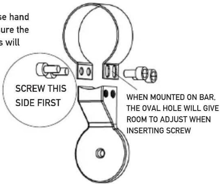
we hand ure the s will SCREW THIS SIDE FIRST WHEN MOUNTED ON BAR, THE OVAL HOLE WILL GIVE ROOM TO ADJUST WHEN INSERTING SCREWWhen using the flush mount brackets, please be sure to use the supplied screws when installing. Select the appropriate gaskets for your bar size, you can mix and match the gaskets if the bar size is slightly smaller or bigger
text_image
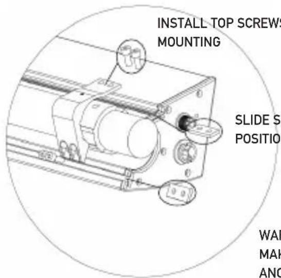
INSTALL TOP SCREWS MOUNTING SLIDE S POSITION WAF MAK ANCSLIDE SCREW ACHORS INTO SLOTS AND POSITION UNDER SCREWS
WARNING : WHEN INSERTING SCREWS, MAKE SURE TO ALIGN SCREW WITH ANCHORS
Connection Descriptions
NOTE:
Be sure to follow specific instructions included with your product. The information below should be used as a general guide only.
RED Power wire (12V+)
- Disconnect negative battery terminal before proceeding. Consult a qualified technician for instructions if you are unsure.
- Plan wire routing before cutting any wires to length. Use a grommet when running wires through the firewall or metal openings.
- Use extreme caution when drilling holes to avoid damaging fuel lines or existing vehicle wiring.
- The +12V wire must be fused within 18" from the battery for protection of the vehicle's electrical system.
BLACK Ground wire (GND)
- Choose a clean unpainted section of metal or the vehicle chassis when attaching the ground wire. Be sure to clean the area of any dirt or grease.
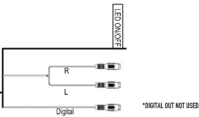
UNIVERSAL DIN CABLE (INCLUDED)
- BLUE LED wire (12V+) - Turns LED ON/OFF
- WHITE/RED RCA - Left/Right audio inputs
- GREY RCA - DIGITAL COAXIAL HI-DEF INPUT (DO NOT CONNECT TO ANALOG AUDIO SOURCE)
NOTE: Some 3rd Party Radios/Source Units might have a preout of 1V or less, this will cause the audio output to sound to sound low. We recommend that a RCA line driver be used in this situation to increase the preout voltage and raise the sound level of the amplifier.
UNIVERSAL CABLE

8 pin waterproof DIN connector
flowchart
graph TD
    A["LED ON/OFF"] --> B["R"]
    A --> C["L"]
    A --> D["Digital"]
*DIGITAL OUT NOT USED
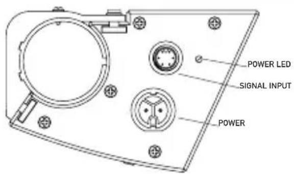
text_image
POWER LED SIGNAL INPUT POWER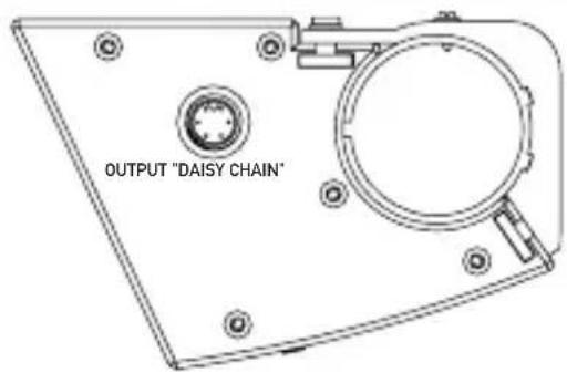
text_image
OUTPUT "DAISY CHAIN"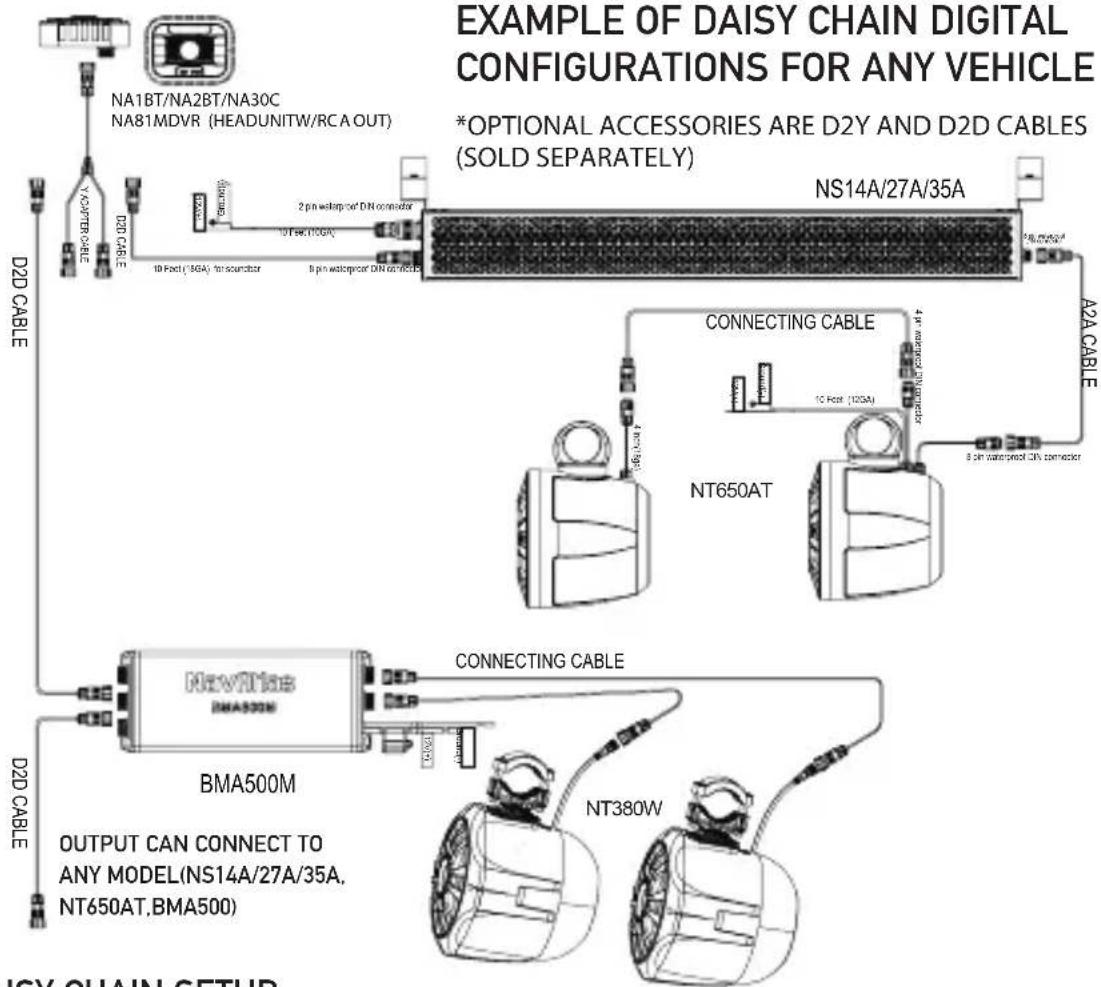
text_image
EXAMPLE OF DAISY CHAIN DIGITAL CONFIGURATIONS FOR ANY VEHICLE *OPTIONAL ACCESSORIES ARE D2Y AND D2D CABLES (SOLD SEPARATELY) NS14A/27A/35A D2D CABLE NA1BT/NA2BT/NA30C NA81MDVR (HEADUNITW/RCA OUT) D2D CABLE 10 Pin (50A) to soundbar 2 pin waterproof DIN connector 10 Pin (100A) 8 Pin waterproof DIN connector A2A CABLE CONNECTING CABLE 10 Pin (100A) 4 Pin waterproof DIN connector NT650AT 8 Pin waterproof DIN connector D2D CABLE BMA500M D2D CABLE CONNECTING CABLE BMA500M OUTPUT CAN CONNECT TO ANY MODEL(NS14A/27A/35A, NT650AT,BMA500) NT380W ISY CHAIN SETUPDAISY CHAIN SETUP USING AFTERMARKET AMPLIFIER
WHEN USING AFTERMARKET AMPLIFIERS WITH SOUNDBARS, YOU MUST USE ANALOG CABLES FOR DASIY CHAIN FUNCTION TO WORK. A2A CABLE(SOLD SEPARATELY) IS REQUIRED FOR ANALOG AUDIO OUTPUT TO WORK IN THIS SETUP.
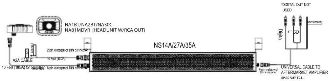
text_image
NA1BT/NA2BT/NA30C NA81MDVR (HEADUNIT W/RCA OUT) A2A CABLE 10 Feet (18GA) for 6µV/4µA; 8 pin waterproof DIN connector 2 pin waterproof DIN connector NS14A/27A/35A *DIGITAL OUT NOT USED Digital UNIVERSAL CABLE TO AFTERMARKET AMPLIFIER :BASS AMP, ECT...IDAISY CHAIN SETUP USING ANALOG SIGNAL
WHEN USING ANALOG RCA FROM A RADIO, THE A2A CABLE(SOLD SEPARATELY) IS REQUIRED FOR DAISY CHAIN FUNCTION TO WORK.

flowchart
graph TD
    A["DXP1000 / DXU1100 / AFTERMARKET RADIO"] --> B["UNIVERSAL CABLE"]
    B --> C["NS14A/27A/35A"]
    C --> D["CONNECTING CABLE"]
    D --> E["NT650AT"]
    E --> F["A2A CABLE"]
    F --> G["BMA500M"]
    G --> H["CONNECTING CABLE"]
    H --> I["NT380W"]
    I --> J["A2A CABLE"]
    J --> K["X310WA"]
    K --> L["X310WP"]
    style A fill:#f9f,stroke:#333
    style B fill:#ccf,stroke:#333
    style C fill:#cfc,stroke:#333
    style D fill:#fcc,stroke:#333
    style E fill:#cff,stroke:#333
    style F fill:#ffc,stroke:#333
    style G fill:#cfc,stroke:#333
    style H fill:#fcc,stroke:#333
    style I fill:#cfc,stroke:#333
    style J fill:#fcc,stroke:#333
    style K fill:#cfc,stroke:#333
    style L fill:#cfc,stroke:#333
Limited One Year Warranty
This warranty gives you specific legal rights. You may also have other rights which vary from state to state.
NavAtlas warrants this product to the original purchaser to be free from defects in material and workmanship for a period of one year from the date of the original purchase.
NavAtlas agrees, at our option, during the warranty period, to repair any defect in material or workmanship or to furnish an equal new, renewed or comparable product (whichever is deemed necessary) in exchange without charges, subject to verification of the defect or malfunction and proof of the date of purchase. Subsequent replacement products are warranted for the balance of the original warranty period.
Who is covered? This warranty is extended to the original retail purchaser for products purchased from an authorized NavAtlas dealer and used in the U.S.A
What is covered? This warranty covers all defects in material and workmanship in this product. The following are not covered: software, installation/removal costs, damage resulting from accident, misuse, abuse, neglect, product modification, improper installation, incorrect line voltage, unauthorized repair or failure to follow instructions supplied with the product, or damage occurring during return shipment of the product.
Factory defects include:
- MID/Tweeter not playing or distorting
- Glue/adhesive separating or not holding correctly
- Tinsel leads not attached/soldered correctly
- LED not working out-of-box
What to do?
- Before you call for service, check the troubleshooting guide in your owner's manual. A slight adjustment of any custom controls may save you a service call.
- If you require service during the warranty period, you must carefully pack the product (preferably in the original package) and ship it by prepaid transportation with a copy of the original receipt from the retailer to an authorized service center.
- Please describe your problem in writing and include your name, a return UPS shipping address (P.O. Box not acceptable), and a daytime phone number with your shipment.
- For more information and for the location of the nearest authorized service center please contact us by one of the following methods:
• Call us 1-562-946-7471
• E-mail us at navcustserv@navatlas.net
Exclusion of Certain Damages: This warranty is exclusive and in lieu of any and all other warranties, expressed or implied, including without limitation the implied warranties of merchantability and fitness for a particular purpose and any obligation, liability, right, claim or remedy in contract or tort, whether or not arising from the company's negligence, actual or imputed. No person or representative is authorized to assume for the company any other liability in connection with the sale of this product. In no event shall the company be liable for indirect, incidental or consequential damages.
EXCHANGE ONLY ON FACTORY DEFECTS, PHYSICAL DAMAGE IS NOT COVERED BY WARRANTY.
Specifications
NS14A/NS27A/NS35A
| size | 14" | 27" | 35" |
| type | Aluminum | Aluminum | Aluminum |
| Driver | 3.5" 2pcs | 3.5" 6pcs | 3.5" 8pcs |
| Voice coil | 0.75" | 0.75" | 0.75" |
| Cone | Aluminum | Aluminum | Aluminum |
| Surround | Rubber surround | Rubber surround | Rubber surround |
| Dust cap | Aluminum | Aluminum | Aluminum |
| Gasket | EVA | EVA | EVA |
| Tweeter | 0.5" 2pcs | 0.5" 4pcs | 0.5" 4pcs |
| X-OVER | HI-6dB/OCT | HI-6dB/OCT | HI-6dB/OCT |
| Power Handeling | 100W | 200W | 200W |
Design and specifications subject to change without notice.
NavAtlas™
Support Line: 1-562-946-7471
9AM-5PM PST Monday-Friday
www.navatlas.com
All rights reserved.
NSA0418-V01
Printed in China