WAP33DC - Access Point Amer - Free user manual and instructions
Find the device manual for free WAP33DC Amer in PDF.

User questions about WAP33DC Amer
0 question about this device. Answer the ones you know or ask your own.
Ask a new question about this device
Download the instructions for your Access Point in PDF format for free! Find your manual WAP33DC - Amer and take your electronic device back in hand. On this page are published all the documents necessary for the use of your device. WAP33DC by Amer.
USER MANUAL WAP33DC Amer
WAP33DC and WAP38DC Wireless Indoor Access Point Installation Manual
Manual Version: v2.0
Content
Chapter 1 Device Introduction 1-1
Chapter 2 Preparation for Installation 2-1
2.1 Installation Precautions 2-1
2.2 Installation Environment Requirements.... 2-1
2.3 Equipment Accessories.... 2-1
2.4 Installation Tools 2-2
Chapter 3 AP Installation 3-1
3.1 Installation Process.... 3-1
3.2 Installation Checklist.... 3-2
3.3 Installation Placement.... 3-2
3.4 Installing the WAP3xDC 3-2
3.4.1 Wall Hanging Installation.... 3-3
3.4.2 T-Keel Installation.... 3-7
3.5 AP Power Options.... 3-9
3.6 Connecting the Internet 3-9
Chapter 1 Device Introduction
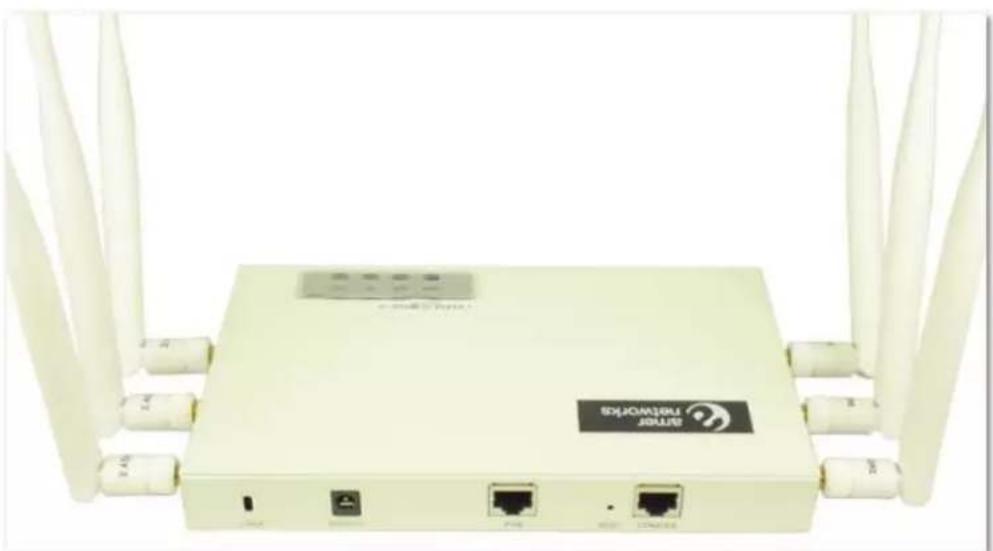
The WAP3xDC series metal indoor wireless access points includes the WAP33DC and WAP38DC:
natural_image
Front view of a beige network router with multiple white antennas and ports (no visible text or symbols on the device body)Fig 1-1 WAP33DC

natural_image
Front view of a beige wireless router with ports labeled LOCK, DC12V, POE, RESET, and COASOLE (no additional text or symbols visible)Fig 1-2 WAP38DC
Quick Specs:
| Product Model WAP33DC WAP38DC | |
| Features | IEEE802.11a/b/g/n IEEE802.11a/b/g/nDouble Radio frequency Double Radio frequency |
| Antenna | Built-out antenna: 2.4G gain 5dBi, Built-in antenna: 2.4G gain 4dBi, 5G gain 5dBi 5G gain 5dBi |
| Power Consumption | 9 Watts (max) 16W (max) |
| Shape Size | 208×125×24mm 250×222×58mm |
| Weight | 0.75kg 0.60kg |
Chapter 2 Preparation for Installation
2.1 Installation Precautions

Warning :
Before the installation and configuration, please read the related security introduction carefully.
- Use the appropriate security measures to avoid personal injury and equipment damage.
- Keep the device clean.
- Do not leave the device on a wet surface.
- Do not leave the device and the installation tools in a busy walking area.
2.2 Installation Environment Requirements
The temperature and humidity environment requirements of the device are as below:
Table 2-1 Temperature Specs
| Items | Range |
| Standard working environment temperature (indoor) | -10°C~55°C |
| Storage temperature | -40°C~70°C |
| Working humidity (non-condensing) | 5%~95% |
2.3 Equipment Accessories
Please refer to the packing list.
2.4 Installation Tools
Recommended tools to use when installing WAP3xDC series access points:
 |  |  |  | 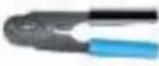 |
| Horizontal ruler | Permanent marker | Knife | Wire stripper | Network pliers |
 |  |  |  | |
| Impact drill (1) and some supporting drills | Rubber hammer | Phillips screwdriver | Ladder |
Chapter 3 AP Installation
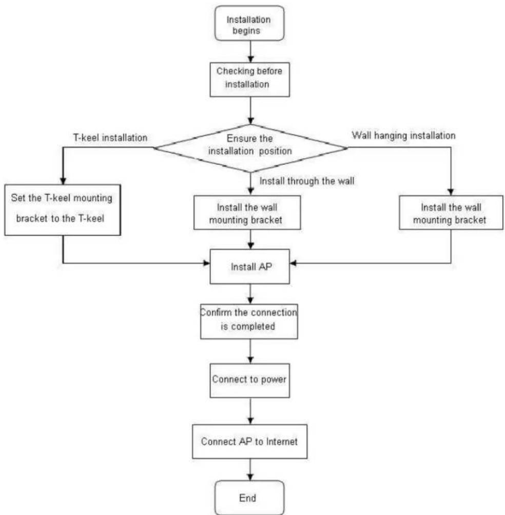
3.1 Installation Process
flowchart
graph TD
    A["Installation begins"] --> B["Checking before installation"]
    B --> C{Ensure the installation position}
    C -->|T-keel installation| D["Set the T-keel mounting bracket to the T-keel"]
    C -->|Wall hanging installation| E["Install the wall mounting bracket"]
    E --> F["Install AP"]
    F --> G["Confirm the connection is completed"]
    G --> H["Connect to power"]
    H --> I["Connect AP to Internet"]
    I --> J["End"]
Fig 3-1 AP installation flow diagram
3.2 Installation Checklist
Check the following items before installing the AP:
- Power on the AP and connect the Ethernet cable. Inspect the LED status to make sure the AP is working normally.
- Record AP's MAC address and serial number (MAC address and serial numbers are located on the back of the AP).
3.3 Installation Placement
Here are some tips for AP placement:
- Cut back the obstacles (such as walls) between AP and the user terminal device as much as possible.
- Install APs far away from electrical devices that create RF noise such as the microwave.
3.4 Installing the WAP3xDC
The installation methods of WAP33DC and WAP38DC are very similar. Both APs can be installed using two methods:
• Wall hanging installation
- T-keel installation
3.4.1 Wall Hanging Installation
Use the wall mounting bracket and the supporting expansion bolts and screws if you plan to install the device to a wall.
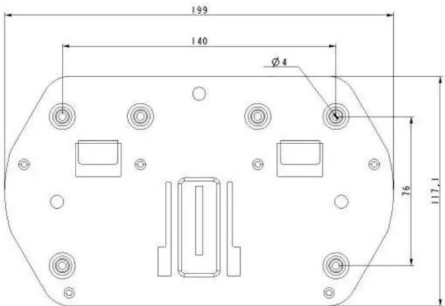
text_image
199 140 Ø 4 76 117,1Fig 3-2 wall mounting bracket size and block diagram (unit: mm)
If you choose to install the AP using the wall hanging method, we recommend connecting the Ethernet cable to the AP first and then install the AP to the wall mounting bracket.
(1) Connect the AP to the POE port by using the cable
Place the mounting kit flat against the wall and mark the holes where the screws are going to be. Punch four holes using an impact drill.
Insert the expansion bolt into the holes and use a hammer it down until the bolt completely goes into the wall.
Match the screw holes to the expansion bolt holes on the wall. The screws should pass through the installation holes of the wall mounting kit. Lock the wall mounting kit to the wall.

text_image
Technical diagram of a device with numbered components and dashed lines indicating assembly or alignmentFig 3-3 Installing the wall mounting bracket to the wall
1: Expansion screws
2: Wall Mounting Kit
3: Pegs 4: Expansion bolts
(2) Match up the mounting holes on the back of AP to the position of the pegs on the wall mounting kit:
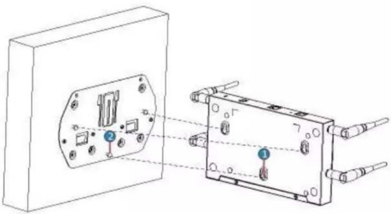
natural_image
Technical line drawing of a device housing with internal components and connectors, showing no text or symbolsFig 3-4 WAP33DC back mounting holes
1: Peg Mounting Hole
2: Pegs
(3) Hang the AP onto the pegs of the wall mounting kit
(4) Place the AP onto the mounting kit, aligning the peg with the peg holes. Slide until the pegs move to the bottom of the holes
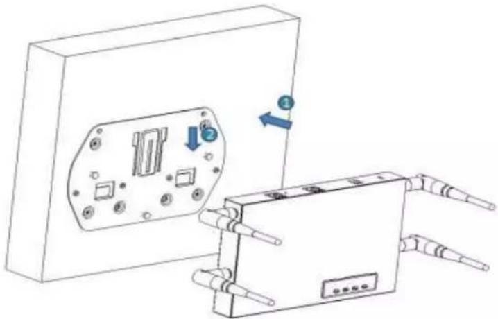
natural_image
Technical line drawing of an electrical enclosure with internal components and a separate device (no text or symbols)Fig 3-5 hang WAP33DC AP to the wall mounting bracket
1: AP
2: Wall Mounting Bracket
The same method applies to the WAP38D:
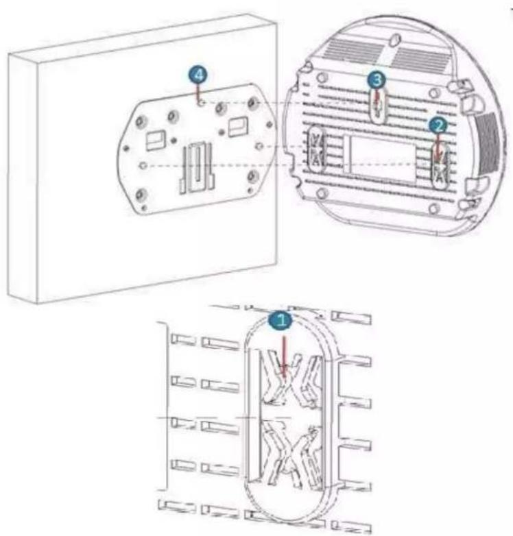
text_image
Technical diagram showing three views of an electrical enclosure with numbered components and internal structure.Fig 3-6 WAP38DC back mounting holes
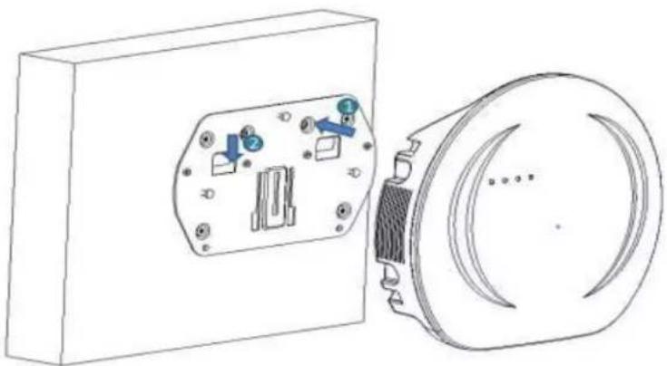
natural_image
Technical line drawing of a device housing with internal components and a circular component (no text or symbols)Fig 3-7 WAP38DC to the wall mounting bracket
(5) Finally, on the WAP33DC, lock the stationary blanks of the chassis to the AP and screw the wall mounting bracket using the M3 screws

natural_image
Diagram of a device with labeled ports and connectors, no readable text or symbols presentFig 3-8 Stationary blanks of the chassis to the wall mounting bracket
1: stationary blanks of the chassis
2: M3 Screw
3.4.2 T-keel Installation
- The width of T-keel is from 12mm to 30mm.
- This installation method is only applied to the T-keel
The square hole on the rail in the wall mounting kit will be used for this method:

text_image
Technical diagram of a mechanical device with numbered components for identificationFig 3-9 T-keel Installation
1: T-keel Mounting Kit
2: Wall Mounting Kit
3: M3×7 Fastening Screws
4: Stationary Blanks of the Chassis
5: M3 Screws
(1) Set the T-keel mounting kit into the rail of the wall mounting kit and place the M3x7 fastening screws through the rail hole of the T-keel mounting kit.
natural_image
Technical diagram of a mechanical or electronic component with labeled parts (no text or symbols present)Fig 3-10 Keel bracket to the T-keel
1: Wall Mounting Kit
2: Square Hole of the Rail
3: T-keel Mounting Kit 4: M3×7 Fastening Screws
(2) Make T-keel stick to the hanging slot of the wall mounting kit:

natural_image
Technical line drawing of a mechanical assembly with mounting holes and a lever (no text or symbols)Fig 3-11 Hook the T-keel to the hanging slot of the wall mounting kit
1: Wall Mounting Kit
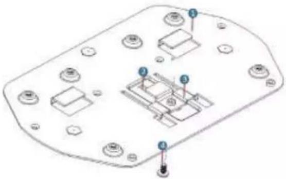
(3) Slide the T-keel mounting kit according to the direction in the following picture. Screw the M3x7 until the T-keel mounting kit is firmly locked in.

text_image
Technical diagram of a mechanical assembly with numbered components and directional arrows indicating movement or assembly.Fig 3-12 T-keel mounting kit
2: T-keel mounting kit
3: M3×8 fastening screws
(4) Use the four M3x7 fastening screws under the T-keel until the T-keel is firmly locked in.
(5) Match the mounting holes on the back of AP with the pegs on the mounting kit. Hang it onto the pegs
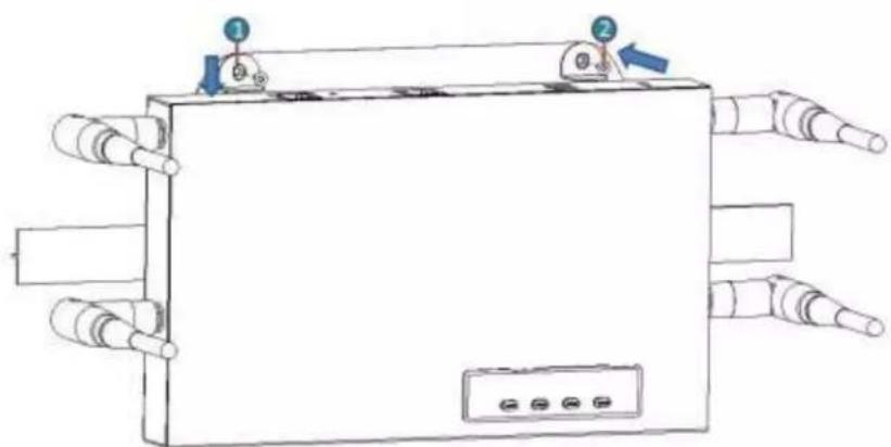
(6) Slide the AP until the pegs pass through the anti-loose hook

text_image
Technical diagram showing a device with labeled components and directional arrows indicating assembly or assembly steps.Fig 3-13 WAP33DC installation

natural_image
Technical line drawing of a mechanical component with mounting holes and internal structure (no text or symbols)Fig 3-14 WAP38DC installation
(7) Close the stationary blanks of the chassis to the AP device using the M3 screws.
natural_image
Diagram of a rectangular device with multiple ports and a control panel, no text or symbols presentFig 3-14 complete the AP installation
(8) Connect AP to the wired LAN/POE by using the cable.
3.5 AP Power Options
The WAP3xDC series supports both local power and PoE.
WAP33DC adopts the 802.3af/802.3at PoE power supply. WAP38DC adopts the 802.3af/802.3at PoE power supply.
Table 3-1 power adapter specifications
| Items | Explanation |
| Power Adapter Input | 100-240V AC |
| Power Adapter Output | +12V---2A |
The WAP3xDC series supports the AC/DC power adapters. You can connect the power interface of the device to local power through the power adapter.
3.6 Connecting to the Internet
The APs can uplink to the Internet or WAN through the Ethernet port. Connect the Ethernet port of the AP to the switch port to achieve an uplink connection.