EliteConnect WAP5110 - Access Point SMC - Free user manual and instructions
Find the device manual for free EliteConnect WAP5110 SMC in PDF.

| Product Type | Wireless Access Point |
| Brand | SMC |
| Model | EliteConnect WAP5110 |
| Wireless Standard | IEEE 802.11g/b |
| Frequency Band | 2.4 GHz |
| Maximum Data Rate | 54 Mbps |
| Antenna Type | 2x External RP-SMA Connectors |
| Ethernet Port | 1x 10/100 Mbps RJ-45 |
| Power Supply | 5V DC, 2A |
| Power over Ethernet (PoE) | No |
| Dimensions (W x D x H) | 9.5 x 7.0 x 2.8 cm |
| Weight | 200 g |
| Wireless Security | WEP 64/128-bit, WPA, WPA2 |
| Management | Web-based GUI, SNMP |
| LED Indicators | Power, LAN, WLAN |
| Reset Button | Yes, on rear panel |
| Mounting Options | Wall-mountable, desktop |
| Operating Temperature | 0°C to 40°C |
| Certifications | FCC, CE |
| Special Features | Supports WDS bridging, VLAN tagging |
Frequently Asked Questions - EliteConnect WAP5110 SMC
User questions about EliteConnect WAP5110 SMC
0 question about this device. Answer the ones you know or ask your own.
Ask a new question about this device
Download the instructions for your Access Point in PDF format for free! Find your manual EliteConnect WAP5110 - SMC and take your electronic device back in hand. On this page are published all the documents necessary for the use of your device. EliteConnect WAP5110 by SMC.
USER MANUAL EliteConnect WAP5110 SMC
IEEE 802.11a/b/g/n Enterprise Access Point
WAP5110

Enterprise Access Point Installation Guide
SMC®
Networks
No. 1, Creation Road III,
Hsinchu Science Park,
30077, Taiwan, R.O.C.
Tel: +886 3 5638888
Fax: +886 3 6686111
March 2013
Pub. # 149100000223A
E032013-CS-R01
Information furnished by SMC Networks, Inc. (SMC) is believed to be accurate and reliable. However, no responsibility is assumed by SMC for its use, nor for any infringements of patents or other rights of third parties which may result from its use. No license is granted by implication or otherwise under any patent or patent rights of SMC. SMC reserves the right to change specifications at any time without notice.
Copyright © 2013 by
SMC Networks, Inc.
No. 1 Creation Road III, Hsinchu Science Park, 30077, Taiwan, R.O.C.
All rights reserved
Trademarks:
SMC is a registered trademark; and EliteConnect, EZ Switch, TigerStack, TigerSwitch, and TigerAccess are trademarks of SMC Networks, Inc. Other product and company names are trademarks or registered trademarks of their respective holders.
Warranty and Product Registration
To register SMC products and to review the detailed warranty statement, please refer to the Support Section of the SMC Website at http://www.smc.com.
How to Use This Guide
This guide includes detailed information on the Access Point (AP) hardware, including network ports, power, and cabling requirements. This guide also provides general installation guidelines and recommended procedures. To deploy this AP effectively and ensure trouble-free operation, you should first read the relevant sections in this guide so that you are familiar with all its hardware components.
Who Should Read This Guide?
This guide is for network administrators and support personnel that install, operate and maintain network equipment. The guide assumes a basic working knowledge of LANs (Local Area Networks) and can be read by those that are new to network equipment, or those with more experience.
How This Guide is Organized
The organization of this guide is based on the AP's main hardware components. Each chapter includes information about a specific component with relevant specifications and installation procedures. AP overview and installation sections are also provided.
For Users New to APs — If you are new to APs, it is recommended that you first read all chapters in this guide before installing the AP.
For Experienced Users— If you are already familiar with installing and operating network APs, Chapters 1 and 2 provide you with enough information to install the AP. Other chapters can be left for reference, when needed.
The guide includes these chapters:
◆ Chapter 1 - Access Point Overview — Includes an overview of the AP with component identification, and key technical specifications.
◆ Chapter 2 - Installation Overview — Includes a list of package contents and an outline of AP installation tasks.
◆ Chapter 3 - AP Enclosure — Includes AP installation on a wall or ceiling.
◆ Chapter 4 - Power Requirements — Includes information on providing power to the AP.
◆ Chapter 5 - Network Connections — Includes information on network interfaces and cabling specifications.
◆ Chapter 6 - AP Management — Connecting to the AP for management and information on the system status LEDs.
Appendix A - Troubleshooting — Information for troubleshooting AP installation and operation.
Related Documentation This guide focuses on AP hardware and installation, it does not cover software configuration of the AP. For specific information on how to operate and use the management functions of the AP, see the following guide:
Management Guide
For all safety information and regulatory statements, see the following documents:
Quick Start Guide
Safety and Regulatory Information
Conventions The following conventions are used throughout this guide to show information:

Note: Emphasizes important information or calls your attention to related features or instructions.

Caution: Alerts you to a potential hazard that could cause loss of data, or damage the system or equipment.

Warning: Alerts you to a potential hazard that could cause personal injury.
Revision History This section summarizes the changes in each revision of this guide.
March 2013 Revision
This is the first revision of this guide.
Contents
Warranty and Product Registration 4
How to Use This Guide 5
Contents 7
Figures 9
Tables 10
1 Access Point Overview 11
Hardware Description 11
Key Hardware Components 12
Key Technical Specifications 14
2 Installation Overview 16
Package Contents 16
AP Installation Tasks 17
3 AP Enclosure 23
General Installation Guidelines 23
AP Location 23
Radio Interference 24
How to Mount the Unit 24
Wall Mounting 24
Suspended Ceiling
T-Rail Mounting 25
4 Power Requirements 27
AC Power Adapter 27
How to Use the AC Power Adapter 28
How to Power the AP Using PoE 29
5 Network Connections 31
Contents
Cable Labeling and Connection Records 32
Understanding the Network Status LED 33
How to Connect to Radio Interfaces 33
How to Connect to the RJ-45 Port 34
Copper Cabling Guidelines 34
10/100BASE-TX Pin Assignments 35
1000BASE-T Pin Assignments 35
Connection Procedure 36
6 AP Management 39
Understanding the System Status LEDs 40
How to Connect to the Console Port 41
How to Reset the AP 43
A
Troubleshooting
Diagnosing LED Indicators 44
System Self-Diagnostic Test Failure 44
Power Problems 44
Installation 45
Wireless Connection Problems 45
In-Band Access 45
Out-of-Band Access 46
Reset the Access Point 46
Index 47
Figures
Figure 1: Front View 12
Figure 2: Rear View 13
Figure 3: Installing the AP on a Wall 17
Figure 4: Installing the AP on a Ceiling T-rail 18
Figure 5: Making a Connection to the RJ-45 Port 18
Figure 6: Connecting the AC Power Adapter 19
Figure 7: System LEDs 20
Figure 8: Console Port Connection 20
Figure 9: Wall Mounting the AP 25
Figure 10: Attaching the AP to a Suspended Ceiling 26
Figure 11: Connecting the AC Power Adapter 28
Figure 12: Connecting to PoE Power 29
Figure 13: Network Status LED 33
Figure 14: RJ-45 Connector 35
Figure 15: Making Twisted-Pair Connections 37
Figure 16: System Status LEDs 40
Figure 17: Console Port Pinout 41
Figure 18: Console Port Connection 42
Figure 19: Reset Button 43
Tables
Table 1: Key Technical Specifications 14
Table 2: AC Power Adapter Specifications 27
Table 3: Network Status LED 33
Table 4: Maximum Twisted-Pair Copper Cable Lengths 34
Table 5: 10/100BASE-TX MDI and MDI-X Port Pinouts 35
Table 6: 1000BASE-T MDI and MDI-X Port Pinouts 36
Table 7: System Status LEDs 40
Table 8: Console Cable Wiring 41
Table 9: Troubleshooting Chart 44
1 Access Point Overview
This chapter includes these sections:
◆ "Hardware Description" on page 11
◆"Key Technical Specifications" on page 14
Hardware Description
The WAP5110 enterprise access point (AP) is built with leading-edge technology to deliver reliable high-performance connectivity for your data network.
The WAP5110 is a dual-band IEEE 802.11a/b/g/n access point that is designed to deliver high-performance wireless services for clients in an enterprise environment. Housed in a compact enclosure, the unit includes its own built-in options for mounting on a wall, or suspended ceiling T-rail. The unit can be powered through a PoE cable connection from a PoE network switch, or from its AC power adapter.
In addition, the AP offers full network management capabilities through an easy-to-use web interface, a command-line interface, and support for Simple Network Management Protocol (SNMP) tools.
Key Hardware Components The WAP5110 consists of several key hardware components. This manual describes each specific component, or related components, together with their installation requirements and procedures in each chapter. To understand each component in detail, refer to the relevant section.
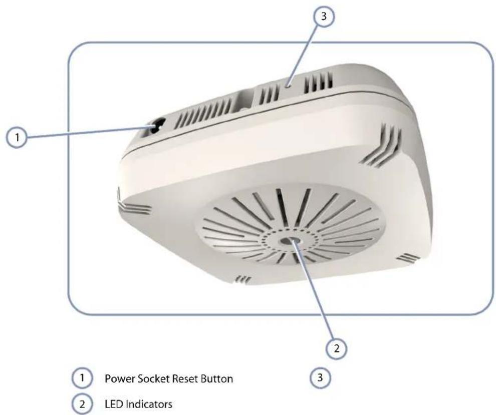
Figure 1: Front View
text_image
1 2 3 Power Socket Reset Button LED IndicatorsPower Socket
If the AP is not powered through a PoE connection to its RJ-45 port, the unit can be powered from its AC power adapter. See "AC Power Adapter" on page 27.
Reset Button
Can be used to return the configuration to factory default values and restart the AP's system software. For more information, see "How to Reset the AP" on page 43.
System LEDs
For information on system status LED indicators, see "Understanding the System Status LEDs" on page 40.
Internal Antennas
The unit includes 2x2 MIMO internal antennas for 2.4 GHz and 5 GHz radio operation.
Figure 2: Rear View

text_image
1 Console Console Ethernet 2 3 4 ① Console Port T-rail Mounting Clamps ② Wall Mounting Slots RJ-45 Ethernet PortRJ-45 Ethernet Port
The RJ-45 port labeled "Ethernet" provides a 1000BASE-T data and Power-over-Ethernet (PoE) power connection to the unit. For more information, see "How to Connect to the RJ-45 Port" on page 34.
Console Port
The port labeled "Console" provides an out-of-band serial connection to a terminal or a PC running terminal emulation software. The port can be used for performing unit monitoring and configuration. For more information, see "How to Connect to the Console Port" on page 41.
Wall/Ceiling Mounting Options
The AP includes built-in mounting slots and clamps that can be used to mount the unit on a wall or a ceiling T-rail. For more information, see "How to Mount the Unit" on page 24.
Key Technical Specifications
The following table contains key system specifications for the AP.
Table 1: Key Technical Specifications
| Item Specification | |
| Ports One 10/100/1000 Mbps RJ-45 port | |
| Network Interface RJ-45 Port:◆ 1000BASE-T, PoE (PD) | |
| Console Port RS-232, RJ-45 connector | |
| 2.4 GHz Radio IEEE 802.11b/g/n | |
| 5 GHz Radio IEEE 802.11a/n | |
| Internal Antennas 2x2 MIMO omni antennas for 2.4 GHz and 5 GHz | |
| Antenna Gain 3 dBi @ 2.4 GHz4 dBi @ 5 GHz | |
| Radio Frequencies 2400 ~ 2483.5 MHz2412 ~ 2472 MHz5745 ~ 5825 MHz (China)5180 ~ 5320 MHz (ETSI)5500 ~ 5700 MHz (ETSI) | |
| LEDs Power, Network | |
| PoE Input Power 37~57 VDC | |
| AC Power Adapter | AC Input: 100 ~ 240 VACDC Output: 12 VDC, 2 A |
| Power Consumption | 22.5 W maximum |
| Enclosure | Plenum-rated plastic (UL2043) |
| Weight | 980 g (2.16 lbs) |
| Size | (W x D x H): 140 x 140 x 47.8 mm (5.51 x 5.51 x 1.88 inches) |
| Temperature | Operating: 0 °C to 40 °C (32 °F to 104 °F)Storage: -20 °C to 70 °C (-4 °F to 158 °F) |
| Humidity | Operating: 5% to 95% (non-condensing) |
2 Installation Overview
This chapter includes these sections:
◆ "Package Contents" on page 16
◆"AP Installation Tasks" on page 17
Package Contents
After unpacking the AP, check the contents to be sure you have received all the components.
◆WAP5110 Enterprise Access Point
◆AC Power adapter
◆Console cable (RJ-45 to DB-9)
◆Quick Start Guide
◆Regulatory and Safety Information
◆ Documentation CD — includes this Installation Guide and the Management Guide
AP Installation Tasks
Follow these tasks to install the AP in your network. For full details on each task, go to the relevant chapter or section by clicking on the link.
Task 1 Unpack package and check contents
Unpack your AP and check the package contents to be sure you have received all the items.
Before installing your AP, be sure to review all the safety statements and guidelines in the Regulatory and Safety Information document.
Task 2 Mount the AP
After planning your installation, mount the unit on a wall or ceiling T-rail.
For more information, go to the chapter "AP Enclosure"
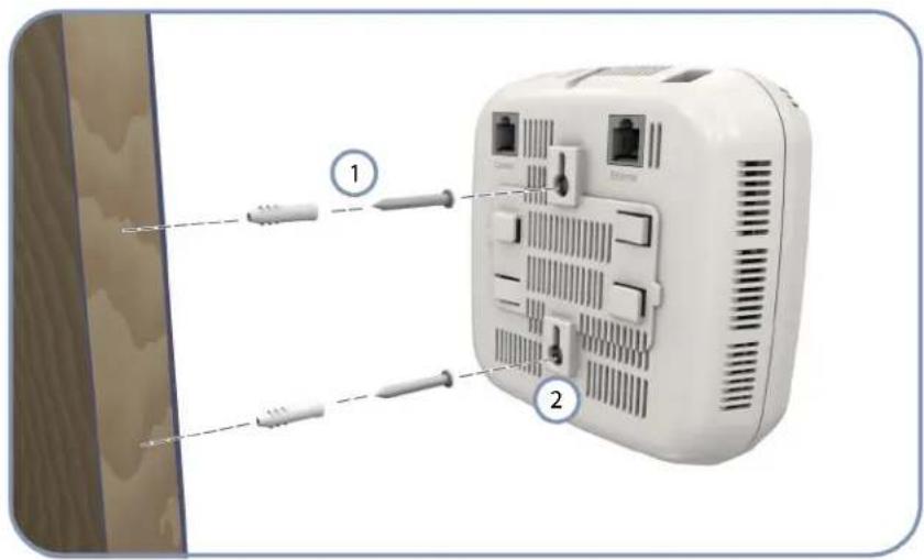
Figure 3: Installing the AP on a Wall
text_image
Diagram of a wall-mounted device with labeled components, showing cable connections and ports1 Set two screws in the wall 6.2 mm (2.4 in.) apart.
2 AP's wall mounting slots down onto the screws so that the unit is secure.
Chapter 2 | Installation Overview
AP Installation Tasks
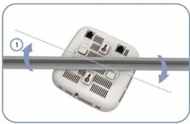
Figure 4: Installing the AP on a Ceiling T-rail
natural_image
Diagram of a device with ports and wiring, showing bidirectional arrows indicating rotation (no text or symbols)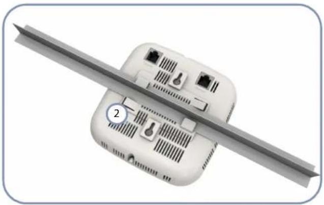
natural_image
3D rendering of a white electronic device with attached circuit breakers and a metallic blade (no text or symbols visible)1 Position the AP's ceiling-mount clip holders on either side of the T-rail.
2 Turn the AP until the two clips lock the AP to the T-rail.
Task 3 Connect Cables
Connect network cable to the RJ-45 port for your network connection. The RJ-45 port connection can also provide PoE power to the unit.

For more information, go to the chapter "Network Connections"
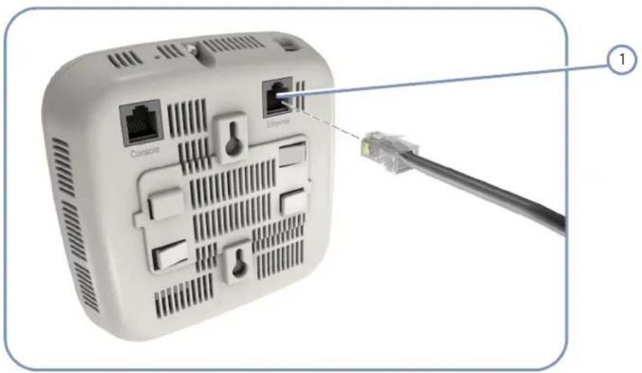
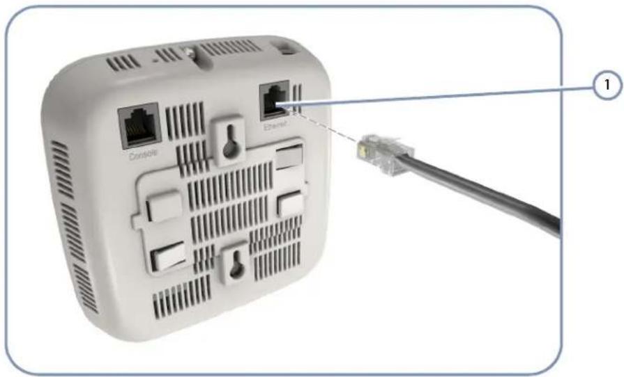
Figure 5: Making a Connection to the RJ-45 Port

natural_image
Front view of a white wireless router with labeled ports and a cable connector (no text or symbols beyond labels)1 Connect Category 5e or better cable to the RJ-45 port.
Task 4 Connect the AC Power Adapter and Power On
Connect the AC power adapter to the AP and to an AC power source.
Alternatively, the AP can be powered by a network connection to the RJ-45 port from a PoE switch.

For more information, go to the chapter "Power Requirements"
Figure 6: Connecting the AC Power Adapter

natural_image
Diagram of a portable electronic device connected to an electrical outlet, showing wiring and power cable (no text or symbols)1 Connect the power adapter to the power socket.
2 Connect the power adapter to a nearby AC power source.
Task 5 Verify AP Operation
Verify basic AP operation by checking the system LEDs.

For more information, go to "Understanding the System Status LEDs"
Figure 7: System LEDs
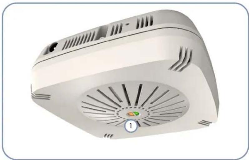
natural_image
3D rendering of a white electronic device with ventilation grilles and a circular indicator labeled '1' (no text or symbols on the device itself)
System Status LEDs.
Task 6 Make Initial Configuration Changes
At this point you may need to make a few basic configuration changes to the AP so that it is compatible with your network. It is suggested to connect to the AP console port to perform this task.

For more information, go to "How to Connect to the Console Port"
Figure 8: Console Port Connection
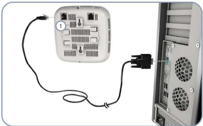
natural_image
Diagram showing a network device connected to an external power outlet, with cable and socket details visible (no text or symbols)
Console Port.
For information on AP configuration:

Refer to the Management Guide.
Chapter 2 | Installation Overview AP Installation Tasks
3 AP Enclosure
The AP includes its own built-in features for mounting the unit to a wall or suspended ceiling T-rail.
Before continuing with AP installation, first review the general guidelines and requirements in this chapter.
This chapter includes these sections:
◆"General Installation Guidelines" on page 23
◆“How to Mount the Unit” on page 24
General Installation Guidelines
Be sure to follow the guidelines below when choosing a location.

Caution: The planning and installation of the AP requires professional personnel that are trained in the installation of radio transmitting equipment. The user is responsible for compliance with local regulations concerning items such as antenna power, use of lightning arrestors, grounding, and radio mast or tower construction. Therefore, it is recommended to consult a professional contractor knowledgeable in local radio regulations prior to equipment installation.
AP Location When planning a location for the AP, consider these guidelines:
When installing for an access point service, be sure to place the unit in a location that can cover the intended service area.
- Mount the AP as high as possible above any obstructions in the coverage area.
◆Avoid mounting next to or near building support columns or other obstructions that may cause reduced signal or null zones in parts of the coverage area.
Mount away from any signal absorbing or reflecting structures (such as those containing metal).
◆Be sure there are no other radio antennas within 2 m (6 ft) of the AP.
◆Place the AP away from power and telephone lines.
Radio Interference
The avoidance of radio interference is an important part of wireless network planning. Interference is caused by other radio transmissions using the same or an adjacent channel frequency. You should first scan your proposed site using a spectrum analyzer to determine if there are any strong radio signals using the 802.11a/b/g/n channel frequencies. Always use a channel frequency that is furthest away from another signal.
How to Mount the Unit
The AP can be mounted in the following ways:
◆To a wall
◆To a suspended ceiling T-rail
The AP includes built-in slots for wall mounting and a T-rail clamp mechanism for mounting the AP to a suspended ceiling.
Wall Mounting
The AP should be mounted only to a wall or wood surface that is at least 1/2-inch plywood or its equivalent. To mount the AP on a wall, always use its wall-mounting slots and mount the unit with the power socket facing up.
Perform the following steps:
- Mark the position of two screw holes on the wall, one above the other, that are vertically 6.2 mm (2.4 in.) apart. For concrete or brick walls, you will need to drill holes and insert wall plugs for the screws.
- Insert the included 20-mm M4 tap screws in the holes leaving the screw heads 2-3 mm from the wall.
- Line up the two mounting slots on the AP with the two screws in the wall, and then slide the AP down onto the screws (see Figure 9).
Figure 9: Wall Mounting the AP
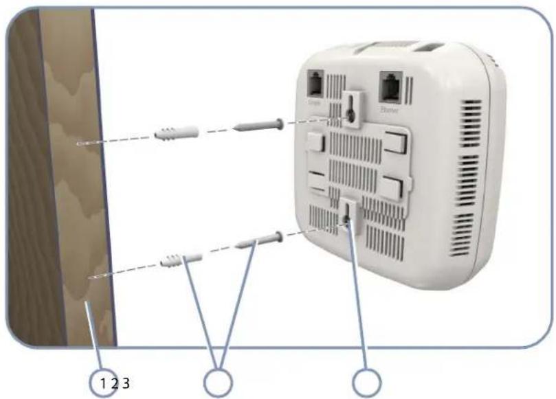
text_image
Diagram of a wall-mounted electronic device with labeled components and wiring connections① Screws and Wall Plugs Wall Mounting Slots ③
2 Wall Structure
Suspended Ceiling To mount the AP to a suspended ceiling T-rail (Figure 10), perform the following steps: T-Rail Mounting
- Choose a location on a ceiling T-rail where the access point will be installed and position the ceiling-mount clip holders on either side of the T-rail.
- Turn the AP until the two clips lock the T-rail into the mounting holders.
Figure 10: Attaching the AP to a Suspended Ceiling

natural_image
Diagram of a wireless router with labeled components and directional arrows indicating flow or movement (no text or symbols present)
natural_image
3D diagram of a white electronic device with attached ports and a metallic blade, labeled with number 3 (no text or symbols on the device itself)1 Ceiling T-rail Mounting Clip
3
2 Mounting Holder
4 Power Requirements
This chapter focuses on how to power-on the AP. The AP can be powered through a PoE connection or by using the included AC power adapter.
This chapter includes these sections:
◆“AC Power Adapter” on page 27
◆“How to Use the AC Power Adapter” on page 28
◆“How to Power the AP Using PoE” on page 29
AC Power Adapter
An AC power adapter is included in the AP package and can be used to power the AP.
The AP does not have a power switch. It is powered on when it is connected to the AC power adapter, and the power adapter is connected to an AC power source. The AC power adapter automatically adjusts to any AC voltage between 100-240 volts at 50 or 60 Hz. No voltage range settings are required.
Table 2: AC Power Adapter Specifications
| Item Description |
| Type Wall plug |
| AC Input 100~240 VAC, 50-60 Hz, 1.0 A |
| DC Output 12 VDC, 2 A |
| Output Power 25 W maximum |
How to Use the AC Power Adapter
To power on the AP using its AC power adapter, perform the following steps:

Caution: Use ONLY the AC power adapter supplied with this AP, otherwise the product may be damaged.

Note: If the AP is connected to both a PoE source device and an AC power source, the AC power connection will be disabled.
- Connect the AC power adapter to the AP and then to an AC power outlet.
- Verify that the Power indicator turns on, and that the other indicators start functioning as described under "Understanding the System Status LEDs" on page 40.
If the Power LED does not turn on green, the self test has not completed correctly. Refer to "Troubleshooting" on page 44.
Figure 11: Connecting the AC Power Adapter

text_image
Diagram of a power supply or appliance with labeled parts: battery, plug, and socket connection.1 AP Power Socket AC Power Source
3
2 AC Power Adapter
How to Power the AP Using PoE
The AP can derive its operating power directly from the RJ-45 port when connected to a network device that provides IEEE 802.3af Power over Ethernet (PoE) or IEEE 802.3at PoE+.
To power on the AP using a PoE connection, perform the following steps:
- Connect the RJ-45 port on the AP to a 10/100/1000 Mbps Ethernet network device, such as a switch, that can supply PoE power.
For more information on network connections, see "How to Connect to the RJ-45 Port" on page 34.

Note: The RJ-45 port on the AP supports automatic MDI/MDI-X operation, so you can use straight-through cables for all network connections.
- Verify that the Power indicator turns on, and that the other indicators start functioning as described under "Understanding the System Status LEDs" on page 40.
Assuming the connected network device is also powered on, the LAN link LED should turn on indicating a valid network connection.
If the Power LED does not turn on green, the self test has not completed correctly. Refer to "Troubleshooting" on page 44.
Figure 12: Connecting to PoE Power
text_image
Constgio Ethernet ①
RJ-45 PoE Port
Chapter 4 | Power Requirements How to Power the AP Using PoE
5 Network Connections
This chapter focuses on making connections to the AP's network interfaces, including details on network cable specifications.
The AP features one 1000BASE-T RJ-45 port, as well as wireless interfaces. The sections that follow describe the network interfaces.
This chapter includes these sections:
◆ "Cable Labeling and Connection Records" on page 32
◆"Understanding the Network Status LED" on page 33
◆“How to Connect to Radio Interfaces” on page 33
◆“How to Connect to the RJ-45 Port” on page 34
Cable Labeling and Connection Records
When planning a network installation, it is essential to label the opposing ends of cables and to record where each cable is connected. Doing so will enable you to easily locate inter-connected devices, isolate faults and change your topology without need for unnecessary time consumption.
To best manage the physical implementations of your network, follow these guidelines:
◆Clearly label the opposing ends of each cable.
Using your building's floor plans, draw a map of the location of all network-connected equipment. For each piece of equipment, identify the devices to which it is connected.
Note the length of each cable and the maximum cable length supported by the switch ports.
For ease of understanding, use a location-based key when assigning prefixes to your cable labeling.
◆Use sequential numbers for cables that originate from the same equipment.
◆Differentiate between racks by naming accordingly.
◆Label each separate piece of equipment.
◆ Display a copy of your equipment map, including keys to all abbreviations at each equipment rack.
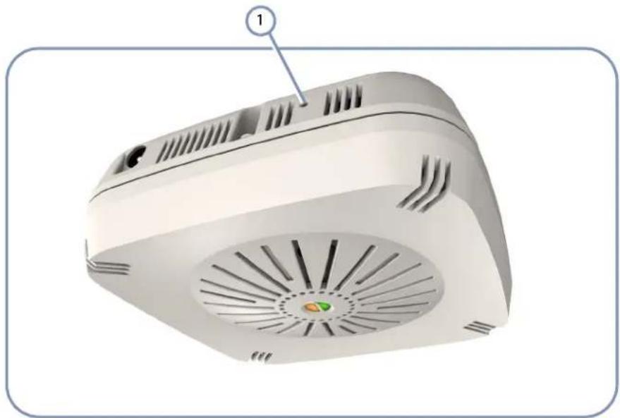
Understanding the Network Status LED
The AP includes an LED indicator to indicate network link status and activity. The LED is shown below and is described in the following table.
Figure 13: Network Status LED

natural_image
3D rendering of a white electronic device with a circular vent and ventilation slots, labeled with number 1 (no text or symbols on the device itself)1 Network Link/Activity
Table 3: Network Status LED
| LED Condition Status | |
| Network Link/Activity | On Amber The 2.4 GHz, 5 GHz, or LAN interface has a valid link.Flashing Amber Flashing indicates network activity.Off The device is powered off. |
How to Connect to Radio Interfaces
The 802.11b/g standard operates in the 2.4 GHz band and the 802.11a standard in the 5 GHz band. The 802.11n standard operates in both the 2.4 GHz and 5 GHz bands. Note that 802.11n is backward compatible with 802.11a, b, and g.
Once the AP is installed and powered on, wireless clients can connect to the 802.11b/g/n radio interface using the 2.4 GHz band and to the 802.11a/n radio interface using the 5 GHz band. The radio and authentication settings for wireless clients can be configured through management interfaces. For more information, refer to the Management Guide.
How to Connect to the RJ-45 Port
The connection between the AP's RJ-45 port and a LAN switch requires an unshielded twisted-pair (UTP) cable with RJ-45 connectors at both ends. Use Category 5, 5e or 6 cable for 1000BASE-T connections, Category 5 or better for 100BASE-TX connections, and Category 3 or better for 10BASE-T connections. The length of the cable must be less than 100m (328 ft).
The RJ-45 port on the AP supports automatic MDI/MDI-X pinout configuration, so you can use standard straight-through twisted-pair cables to connect to any other network device (PCs, servers, switches, routers, or hubs).
Table 4: Maximum Twisted-Pair Copper Cable Lengths
| Cable Type Maximum Cable Length Connector |
| 1000BASE-T |
| Category 5, 5e, or 6 100-ohm UTP or STP 100 m (328 ft) RJ-45 |
| 100BASE-TX |
| Category 5 or better 100-ohm UTP or STP 100 m (328 ft) RJ-45 |
| 10BASE-T |
| Category 3 or better 100-ohm UTP 100 m (328 ft) RJ-45 |
Copper Cabling Guidelines
To ensure proper operation when installing the AP into a network, make sure that the current cables are suitable for 10BASE-T, 100BASE-TX or 1000BASE-T operation. Check the following criteria against the current installation of your network:
Cable type: Unshielded twisted pair (UTP) or shielded twisted pair (STP) cables with RJ-45 connectors; Category 3 or better for 10BASE-T, Category 5 or better for 100BASE-TX, and Category 5, 5e or 6 for 1000BASE-T.
◆ Protection from radio frequency interference emissions
◆Electrical surge suppression
Separation of electrical wires (switch related or other) and electromagnetic fields from data based network wiring
◆Safe connections with no damaged cables, connectors or shields
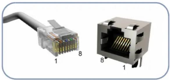
10/100BASE-TX Pin Assignments
Most 100BASE-TX RJ-45 ports support automatic MDI/MDI-X operation, so you can use straight-through or crossover cables for all network connections to PCs, switches, or hubs. In straight-through cable, pins 1, 2, 3, and 6, at one end of the cable, are connected straight through to pins 1, 2, 3, and 6 at the other end of the cable.
Figure 14: RJ-45 Connector

natural_image
Diagram of a network switch with labeled pins (1 and 8), showing internal structure without any text or symbols beyond labels1 RJ-45 Pin Numbers
Table 5: 10/100BASE-TX MDI and MDI-X Port Pinouts
| PIN | MDI Signal Name ^a | MDI-X Signal Name | ||||||
| 1 | Transmit Data plus (TD+) -52V power (Negative V_port ) | Receive Data plus (RD+) GND (Positive V_port ) | ||||||
| 2 | Transmit Data minus (TD-) -52V power (Negative V_port ) | Receive Data minus (RD-) GND (Positive V_port ) | ||||||
| 3 | Receive Data plus (RD+) GND (Positive V_port ) | Transmit Data plus (TD+) -52V power (Negative V_port ) | ||||||
| 4 | -52V power (Negative V port) | GND (Positive V port) | ||||||
| 5 | -52V power (Negative V port) | GND (Positive V port) | ||||||
| 6 | R e GND (Positive V_port ) | c | e | Transmit Data minus (TD-) -52V power (Negative V_port ) | e | D | ||
| 7 | GND (Positive V port) | - | 5_port | 2 | ||||
| 8 | GND (Positive V port) | - | 5_port | 2 | ||||
a. The "+" and "-" signs represent the polarity of the wires that make up each wire pair.
1000BASE-T Pin Assignments
All 1000BASE-T ports support automatic MDI/MDI-X operation, so you can use straight-through cables for all network connections to PCs or servers, switches or hubs.
The table below shows the 1000BASE-T MDI and MDI-X port pinouts. These ports require that all four pairs of wires be connected. Note that for 1000BASE-T operation, all four pairs of wires are used for both transmit and receive.
Table 6: 1000BASE-T MDI and MDI-X Port Pinouts
| Pin MDI Signal Name MDI-X Signal Name | |
| 1 Bi-directional Pair A Plus (BI_DA+) -52V power (Negative V_port ) | Bi-directional Pair B Plus (BI_DB+) GND (Positive V_port ) |
| 2 Bi-directional Pair A Minus (BI_DA-) -52V power (Negative V_port ) | Bi-directional Pair B Minus (BI_DB-) GND (Positive V_port ) |
| 3 Bi-directional Pair B Plus (BI_DB+) GND (Positive V_port ) | Bi-directional Pair A Plus (BI_DA+) -52V power (Negative V_port ) |
| 4 Bi-directional Pair C Plus (BI_DC+) -52V power (Negative V_port ) | Bi-directional Pair D Plus (BI_DD+) GND (Positive V_port ) |
| 5 Bi-directional Pair C Minus (BI_DC-) -52V power (Negative V_port ) | Bi-directional Pair D Minus (BI_DD-) GND (Positive V_port ) |
| 6 Bi-directional Pair B Minus (BI_DB-) GND (Positive V_port ) | Bi-directional Pair A Minus (BI_DA-) -52V power (Negative V_port ) |
| 7 Bi-directional Pair D Plus (BI_DD+) GND (Positive V_port ) | Bi-directional Pair C Plus (BI_DC+) -52V power (Negative V_port ) |
| 8 Bi-directional Pair D Minus (BI_DD-) GND (Positive V_port ) | Bi-directional Pair C Minus (BI_DC-) -52V power (Negative V_port ) |
1000BASE-T Cable Requirements
All Category 5 UTP cables that are used for 100BASE-TX connections should also work for 1000BASE-T, providing that all four wire pairs are connected. However, it is recommended that for all critical connections, or any new cable installations, Category 5e (enhanced Category 5) or Category 6 cable should be used. The Category 5e and 6 specifications include test parameters that are only recommendations for Category 5. Therefore, the first step in preparing existing Category 5 cabling for running 1000BASE-T is a simple test of the cable installation to be sure that it complies with the IEEE 802.3-2008 standards.
Connection Procedure
Follow these steps to connect Ethernet copper cable to the AP's RJ-45 twisted-pair copper port:

Note: Connecting Ethernet cable to the AP and to a PoE LAN switch powers on the unit.
- Attach one end of a twisted-pair cable segment to the network device's RJ-45 port.
Figure 15: Making Twisted-Pair Connections
text_image
Cordio Ethernet ①1 RJ-45 Ethernet Port
- Attach the other end to the RJ-45 port on the AP.
Make sure the twisted pair cable does not exceed 100 meters (328 ft) in length.
- As the connection is made, check that the attached network device port LED turns on to indicate that the connection is valid.
Chapter 5 | Network Connections How to Connect to the RJ-45 Port
6 AP Management
The AP includes a management agent that allows you to configure or monitor the AP using its embedded management software. To manage the AP, you can make a direct connection to the console port (out-of-band), or you can manage it through a network connection (in-band) using Telnet, Secure Shell (SSH), a web browser, or SNMP-based network management software.
For a detailed description of the AP's software features, refer to the Management Guide.
This chapter includes these sections:
◆“Understanding the System Status LEDs” on page 40
◆“How to Connect to the Console Port” on page 41
◆ "How to Reset the AP" on page 43
Understanding the System Status LEDs
The AP includes LED indicators that indicate system and port status. The LEDs are shown below and are described in the following table.
Figure 16: System Status LEDs

natural_image
3D rendering of a white electronic device with ventilation slots and a central hub, labeled with numbers 1 and 2 pointing to the center (no text or symbols on the device itself)1 Network Link/Activity Power/Diagnostic 2
Table 7: System Status LEDs
| LED Condition Status | |
| Power/Diagnostic On Green The AP is receiving power and operating normally. | |
| Flashing Green Initial system self-test in progress. | |
| Off The AP is not receiving power. | |
| Network Link/Activity | On Amber The 2.4 GHz, 5 GHz, or LAN interface has a valid link. |
| Flashing Amber Flashing indicates network activity. | |
| Off The AP is not receiving power. | |
How to Connect to the Console Port
The RJ-45 Console port on the AP is used to connect to the AP for out-of-band console configuration. The console device can be a PC or workstation running a VT-100 terminal emulator, or a VT-100 terminal. A console cable is supplied with the AP for connecting to a PC's RS-232 serial DB-9 DTE (COM) port.

Note: To connect to notebooks or other PCs that do not have a DB-9 COM port, use a USB to male DB-9 adapter cable (not included with the AP).
Figure 17: Console Port Pinout
natural_image
Two views of a network switch (NCS) showing internal structure and cable, no text or symbols present.The following table describes the pin assignments used in the console cable.
Table 8: Console Cable Wiring
| AP's 8-Pin RJ-45 Console Port | Null Modem PC's 9-Pin DTE Port |
| 6 RXD (receive data) <----3 TXD (transmit data) | |
| 3 TXD (transmit data) ---->2 RXD (receive data) | |
| 5 SGND (signal ground) ----5 SGND (signal ground) | |
No other pins are used.
The serial port's configuration requirements are as follows:
◆Default Baud rate—115,200 bps
◆Character Size—8 Characters
Parity—None
◆Stop bit—One
◆Data bits—8
◆Flow control—none
Follow these steps to connect to the Console port:
- Attach one end of the included console cable to a DB-9 COM port connector on the management PC. Use a USB to male DB-9 adapter cable (not included) if needed.
- Attach the other end of the console cable to the RJ-45 Console port on the AP.
Figure 18: Console Port Connection

natural_image
Diagram showing a device with cable and connector, connected to an open computer tower (no text or symbols visible)1 Console Port
- Configure the PC's COM port required settings using VT-100 terminal emulator software (such as HyperTerminal) running on the management PC.
- When you have completed your console session, remove the console cable from the AP.
For a detailed description of connecting to the console and using the AP's command-line interface (CLI), refer to the Management Guide.
How to Reset the AP
The Reset button on the AP can be used to restart the device and set the configuration back to factory default values.
Use a sharp object, such as the tip of a pen, to depress the Reset button. One push of the button restarts the system software using default values.
Figure 19: Reset Button
natural_image
3D rendering of a white electronic device with ventilation grilles and a labeled component (1), no visible text or symbols beyond the label.1 Reset Button
A Troubleshooting
Diagnosing LED Indicators
Table 9: Troubleshooting Chart
| Symptom Action | |
| Power LED is Off | Check connections between the power adapter and the wall outlet.Check the LAN connection if using PoE power.Contact your dealer for assistance. |
| Power LED is Flashing Green | Power cycle the AP to try and clear the condition.If the condition does not clear, contact your dealer for assistance. |
| Network LED is Off | Verify that the AP and attached device are powered on.Using management interfaces, verify that the 2.4 GHz and 5 GHz radios are enabled.Be sure the network cable is plugged into both the AP and corresponding device.Verify that the proper cable type is used and its length does not exceed specified limits.Check the cable connections for possible defects. Replace the defective cable if necessary. |
System Self-Diagnostic Test Failure
If the Power LED indicates a failure of the system power-on-self-test (POST), you can use a console connection to view the POST results. The POST results may indicate a failed component or help troubleshoot the problem. For more information on connecting to the console port and using the CLI, refer to the Management Guide.
Note a POST failure normally indicates a serious hardware fault that cannot be rectified or worked around. If you encounter a POST failure, you should contact your dealer for assistance.
Power Problems
If the power indicator does not turn on when the power adapter is plugged in, you may have a problem with the power outlet, power cord, or power adapter. However, if the unit powers off after running for a while, check for loose power
connections, power losses or surges at the power outlet. If you still cannot isolate the problem, the power adapter may be defective.
Installation
Verify that all system components have been properly installed. If one or more components appear to be malfunctioning (such as the power cord or network cabling), test them in an alternate environment where you are sure that all the other components are functioning properly.
Wireless Connection Problems
If wireless clients cannot access the network, check the following items before you contact your local dealer for assistance:
◆Be sure the access point and wireless clients are configured with the same Service Set ID (SSID).
◆ Ensure that wireless clients are properly configured with the appropriate authentication or encryption keys.
If authentication is being performed through a RADIUS server, ensure that the clients are properly configured on the RADIUS server.
If authentication is being performed through IEEE 802.1X, be sure the wireless users have installed and properly configured 802.1X client software.
In-Band Access
If the AP cannot be configured using Telnet, a web browser, or SNMP software:
◆Be sure to have configured the AP with a valid IP address, subnet mask and default gateway.
◆Check that you have a valid network connection to the AP and that the Ethernet port or the wireless interface that you are using has not been disabled.
If you are connecting to the AP through the wired Ethernet interface, check the network cabling between the management station and the AP. If you are connecting to the AP from a wireless client, ensure that you have a valid connection to the AP.
If you cannot connect using Telnet, you may have exceeded the maximum number of concurrent Telnet sessions permitted (i.e., four sessions). Try connecting again at a later time.
Out-of-Band Access
If you cannot access the on-board configuration program via a serial port connection:
◆Be sure you have set the terminal emulator program to VT100 compatible, 8 data bits, 1 stop bit, no parity and 115,200 Baud Rate.
◆Check that the null-modem serial cable conforms to the pin-out connections provided in "How to Connect to the Console Port" on page 41.
Reset the Access Point
If all other recovery measure fail, and the AP is still not functioning properly, take any of these steps to reset the AP's hardware:
◆Enter the "reload" command from the console interface.
◆ Restart the AP from the web interface.
◆Perform a power reset.
◆Press the Reset button to restore the factory default values.
Index
Numerics
10/100 pin assignments 35
1000BASE-T pin assignments 35
A
antenna position 23
antennas, external 13
B
basic installation tasks 17
baud rate, console 41
bracket kit 13
C
cable
Ethernet cable compatibility 34
labeling and connection records 32
console port 13
console port, pin assignments 41
contents of package 16
copper cable connection 34
D
diagnosing LED indicators 44
diagnostic test failure 44
E
environmental specifications 14
equipment checklist 16
Ethernet RJ-45 port 13
external antennas 13
H
hardware errors 44
hardware overview 11
hardware specifications 14
humidity specifications 14
|
in-band access 45
indicators, LED 33, 40
injector module 12
installation tasks 17
installation troubleshooting 45
interference, radio 24
introduction 16
K
key components 12
L
LED indicators
port 33,40
link status LEDs 33
location guidelines 23
M
management
out-of-band 39
web-based 39
mounting the AP 24
0
operating temperature 14
out-of-band access 46
out-of-band management 39
overview of hardware 11
P
package contents 16
pin assignments
console port 41
RJ-45 port 35
planning guidelines 23
PoE injector module 27
PoE port 13
pole mount bracket 13
port LEDs 33
position of AP 23
POST failure 44
power injector 12, 27
power problems 44
Index
product overview 11
R
radio interfaces, connecting 33
radio interference 24
reset.AP 46
RJ-45 connection 34
RJ-45 port 13
S
serial port 13
site selection 23
specifications, key 14
status LEDs 33, 40
system LEDs 12, 40
T
tasks, installation 17
technical specifications 14
temperature specifications 14
troubleshooting LEDs 44
W
wall mount bracket 13
wall mounting 24
web-based management 39
wireless problems 45
Headquarters
No. 1, Creation Rd. III
Hsinchu Science Park
Taiwan 30077
Tel: +886 3 5638888
Fax: +886 3 6686111
English: Technical Support information available at www.smc.com
English: (for Asia-Pacific): Technical Support information at www.smc-asia.com
E-mail address: www.smc.com→ Support→ By email
Driver updates: www smc com→ Support→ Downloads