TruVision - Security Camera GE - Free user manual and instructions
Find the device manual for free TruVision GE in PDF.

User questions about TruVision GE
0 question about this device. Answer the ones you know or ask your own.
Ask a new question about this device
Download the instructions for your Security Camera in PDF format for free! Find your manual TruVision - GE and take your electronic device back in hand. On this page are published all the documents necessary for the use of your device. TruVision by GE.
USER MANUAL TruVision GE
TruVision Megapixel IP Camera Quick Start Guide
Copyright © 2010 UTC Fire & Security. All rights reserved.
Trademarks and Patents The TruVision name and logo are trademarks of UTC Fire & Security.
GE and the GE monogram are trademarks of the General Electric Company and are under license to UTC Fire & Security, 9 Farm Springs Road, Farmington, CT 06034-4065, USA
Contact information For contact information, see www.utcfireandsecurity.com.
Content
Introduction 4
Package contents 4
Installation environment 4
Cable requirements 4
Camera description 5
Setting up the camera 6
Connecting the devices 7
Accessing the camera over the internet 8
Overview of the Web browser window 9
Network and streaming configuration 10
Configuring the camera 12
1.3 megapixel camera main menu 13
2.0 megapixel camera main menu 13
Specifications 14
Introduction
This pocket guide provides basic information on setting up and using the TruVision megapixel cameras.
1.3 megapixel box cameras:
- TVC-M1120-1-N
- TVC-M1120-1-P
2.0 megapixel box cameras:
- TVC-M2110-1-N
- TVC-M2110-1-P
Package contents
The camera is shipped with the following items:
- Camera
• Multilingual Quick Start Guide
• CD with User Manual in several languages
Installation environment
Refer to the user manual for detailed information, but observe these important requirements:
- Place the camera in a secure location.
- Ensure that the camera is in a well-ventilated area.
- Do not expose the camera to rain or moisture.
Cable requirements
Cable type Requirements
Data For RS-485: 22 gauge (0.64 mm) shielded, two-conductor, twisted-pair (STP) cable
Cable type Requirements
Video 75 ohm coaxial cable with BNC ends
Power 24 VAC cable
Camera description
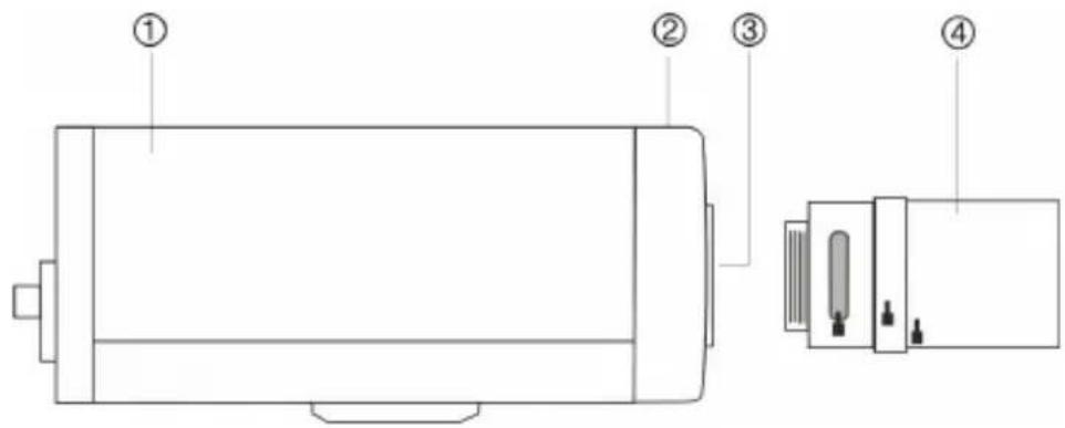
Figure 1: Side view of 1.3 megapixel box camera

text_image
Diagram of a device with labeled components including a connector, cable, and socket, plus an inset showing a socket with four pins.- Camera
- Auto iris lens connector
Video-type auto iris lens connection:
A. Power; B. NC; C. Video;
D. GND
DC-type auto iris lens connection:
A. Damping coil (-); B.
Damping coil (+); C. Driving
coil (-); D. Driving coil (+)
- Focus adjustment
- Lens interface
- C-mount adaptor (for C-mount lenses only). Not included
- Lens (auto iris lens shown. Manual lens has no cable.) Not included
- Auto iris lens cable. Not included
Figure 2: Side view of 2.0 megapixel box camera
text_image
Technical diagram of a device with numbered components, including front and side views with labeled parts.-
Camera
-
Lens interface
-
Focus adjustment
-
Lens. Not included
Setting up the camera
Note: If the light source where the camera is installed experiences rapid, wide variations in lighting, the camera may not operate as intended.
For detailed instructions, please refer to the user manual.
To quickly put the camera into operation:
- Prepare the mounting surface.
- Mount the camera to the wall/ceiling using the appropriate fasteners. See the user manual for further details.
- Connect the cables to the camera. See "Connecting the devices" on page 7.
- Set up the camera's network and streaming parameters so that the camera can be controlled over the network. See "Accessing the camera over the internet" on page 8.
- Program the camera to suit its location. See "Configuring the camera" on page 12.
- Set up the connections to a DVR and configure the DVR for the camera.
Connecting the devices

text_image
LAN/WAN LAN(POE) AUDIO IN OUT RS-485 VIDEO OUT AC 24V/DC 12V PWR ① ② ③ ④ ⑤ ⑥ ⑦ ⑧ ⑨ ⑩ ⑪- Ethernet RJ45 port. Connect to network devices.
- Audio input. Connect to an audio input.
- Audio output. Connect to an audio output.
- Video output. Connect to a CCTV monitor.
- SDHC card slot. Insert an 8GB or 16GB SDHC card for local storage as a backup in case of network failure, for example.
- Power supply. Connect to 12 VDC or 24 VAC power supply.
- Power supply LED
- RS-485 D+, D-. Connect to an RS-485 device such as a PTZ dome camera.
- Alarm input N, G. Connect to an alarm input device.
-
Ground. Connect to ground.
-
Alarm output 1A(+), 1B(-). Connect to an alarm output device. Connect a 12 VDC/30 mA external power supply to the alarm output. See Figure 3 below.
Figure 3: External alarm output

text_image
1A 1B DC JJ1Accessing the camera over the internet
The camera Web browser lets you view, record, and play back recorded videos as well as manage the camera from any PC with Internet access.
To access the camera online:
- In the Web browser enter the camera's IP address. Use the tool, IP Finder, enclosed on the CD to find the IP address of the camera.
The Login dialog box appears.
- Enter your user name and password.
User name: admin
Password: 1234
Click OK. The Web browser window appears in live mode. See Figure 4 on page 9.
Note: The live screen is initially blank. You must click the Start Live View icon on the bottom of the screen for the live mode images to appear on-screen.
Overview of the Web browser window
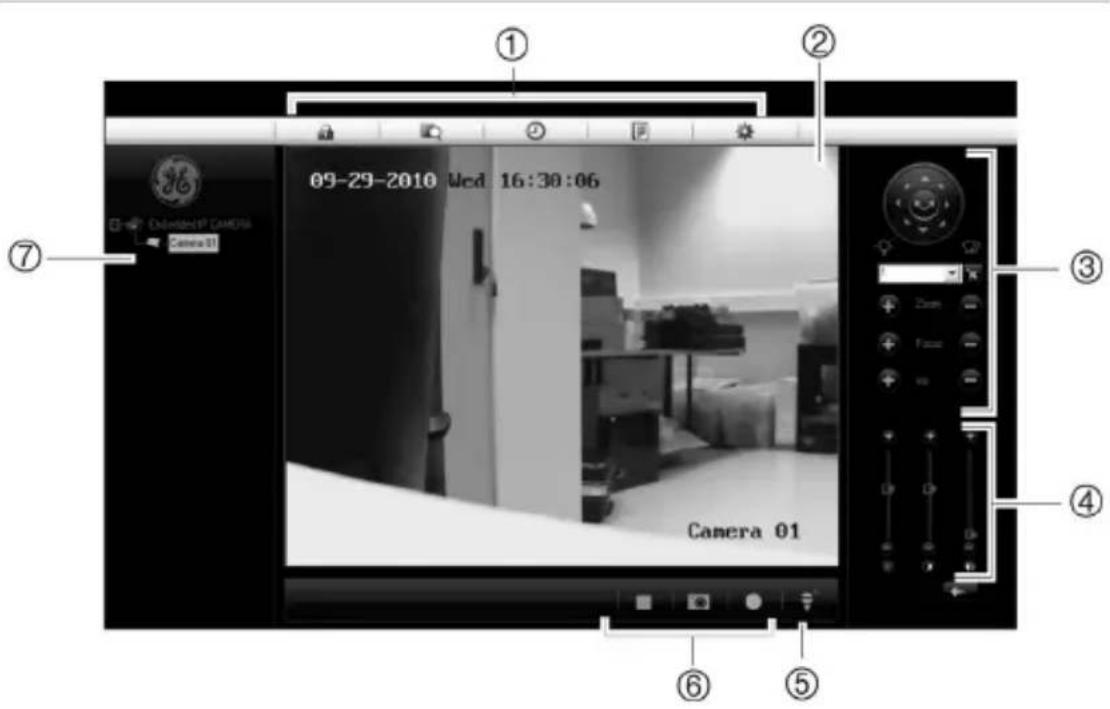
Figure 4: Web browser interface
text_image
① ② ③ ④ ⑥ ⑤ ⑦ 09-29-2010 Wed 16:30:06 Camera 01 Camera 01- Menu toolbar. Lets you do the following:
 | Log on and log off the system. This can only be done in live mode. |
 | View live video. |
 | Play back video. |
 | Search for event logs. There are four main information types: All, Alarm, Notification and Operation. |
 | |
| Configure settings. |
Note: The Playback and Log functions can only be used when an SDHC card is inserted in the camera.
-
Viewer. View live or playback video.
-
PTZ controls. Lets you control a PTZ camera when connected using RS-485 port. Also used to access main menu via "Preset 95" to configure the camera.
- Video image settings. Adjust video image settings such as brightness, contrast, saturation, and hue.
- Audio setting. Turn bi-directional audio on or off.
- Video function. Lets you do the following:

Record live video.

Take a snapshot of the video.

Start live view.
- Camera. View video and record video from this camera.
Network and streaming configuration
Once the camera hardware has been installed, the camera can then be configured over the network.
In the camera browser screen click the Config button in the menu toolbar to get the configuration screens. There are 10 folders running down the left side of the screen and each folder has a list of subfolders which display the different configuration screens. See the Figure 5 on page 11 for an example.
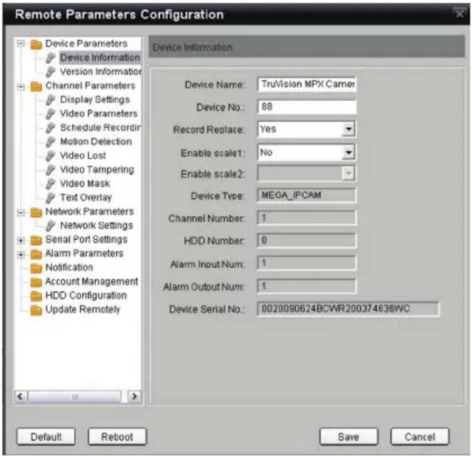
Figure 5: Example of a configuration screen - Device parameters
text_image
Remote Parameters Configuration Device Information Device Name: TruVision MPX Camer Device No.: 88 Record Replace: Yes Enable scale1: No Enable scale2: Device Type: MEGA_IPCAM Channel Number: 1 HDD Number: 0 Alarm Input Num: 1 Alarm Output Num: 1 Device Serial No.: 0020090624BCWR200374636WC Default Reboot Save CancelNote: The On-screen display (OSD) menus are in English only.
Table 1: Overview of the configuration parameters
| Configuration folder Description | |
| Device information | Defines the device name and number as well as enables the overwrite and video scaler options. |
| Channel parameters | Defines the OSD properties of camera information, recording schedule, recording settings for alarm events, alarm response, and overlay text. |
| Network parameters | Defines the network parameters required to access the camera over the internet. |
| Serial port settings | Defines the RS485 communication settings. |
| Alarm parameters | Defines how the camera handles alarms such as input type, notification of alarms, and response schedules and duration. |
| Notification parameters | Defines the methods to be used to alert for internal errors in the system. |
| User management | Defines who can use the camera, their passwords and access privileges. |
| HDD configuration | Defines how to format the SDD card used in the camera. |
| Upgrade remotely | Defines how to upgrade the camera's firmware. |
Configuring the camera
The cameras are programmed through an on-screen (OSD) menu. This main menu lets you set up the camera image to suit your installation.
To access the main menu:
- Open the browser and enter the camera IP address to connect to the camera. Use the tool, IP Finder, enclosed on the CD to find the IP address of the camera.
- Enter your user name and password in the Login box and click OK. The Web browser screen appears in live mode.
- From the preset drop-down list in the PTZ control section of the Web browser screen select preset number 95. The main menu appears.
Refer to the User Manual for detailed information on configuring the cameras.
1.3 megapixel camera main menu
LANGUAGE ENGLISH
RESOLUTION HD(1200*720)
FRAME 25fps
LENS AI
SHUTTER 1/25 S
AUTO GAIN HIGH
DAY/NIGHT DAY
◆ WHITE BALANCE
BACKLIGHT COMP MANUAL...
MIRROR OFF
<EXIT> <SAVE>
2.0 megapixel camera main menu
LANGUAGE ENGLISH
FLICKER CONTROL 50Hz
RESOLUTION UXGA(1600*1200)
FRAME 12.5fps
SHUTTER OFF
AUTO GAIN OFF
DAY/NIGHT DAY
WHITE BALANCE AUTO
EFFECTS MODE OFF
MIRROR OFF
EPTZ ON
<EXIT> <SAVE>
| Operating temperature -10 to +60 °C(14 to 140 °F) |
| Power supply 24 VAC ±10% / 12VDC ±10%, PoE (Power over Ethernet) |
| Power consumption 4 W max. (10 W max. with ICR working) |
| Dimensions 1.3 megapixel IP camera: |
| 68 × 63 × 158 mm (2.71 × 2.48 × 6.25 inches) |
| 2.0 megapixel IP camera: |
| 65 × 63 × 158 mm (2.56 × 2.48 × 6.25 inches) |
| Weight 600 g (1.32 lbs) |