DSV3K-LS - Amplifier Kramer - Free user manual and instructions
Find the device manual for free DSV3K-LS Kramer in PDF.

User questions about DSV3K-LS Kramer
0 question about this device. Answer the ones you know or ask your own.
Ask a new question about this device
Download the instructions for your Amplifier in PDF format for free! Find your manual DSV3K-LS - Kramer and take your electronic device back in hand. On this page are published all the documents necessary for the use of your device. DSV3K-LS by Kramer.
USER MANUAL DSV3K-LS Kramer
2.1 Achieving the Best Performance 2
2.2 Safety Instructions 3
2.3 Recycling Kramer Products 3
3 Overview 4
3.1 System Overview 4
3.2 Transmitter and Broadcaster 6
3.3 Receivers 7
3.4 Receiver DCL 7
3.5 Line Splitter Long 8
3.6 LEDs 9
4 Connecting the DS Vision® 3000 10
4.1 Broadcaster/Transmitter Connections 11
4.2 Receiver/Receiver L Connections 11
4.3 Receiver DCL Connections 11
4.4 Connecting CATx Cables 12
4.5 Connecting to the Power Supply 12
4.6 Adjusting the Picture Quality 12
4.7 Note on Serial Extension: 12
5 Technical Specifications 13
Figures
Figure 1: DS Vision 3000 System Overview 5
Figure 2: DS Vision 3000 Standard Range 5
Figure 3: DS Vision 3000 Extended Range with Splitter 5
Figure 4: Broadcaster Unit - 8 Ports 6
Figure 5: Receiver Ports 7
Figure 6: Receiver DCL Front and Back Connections 8
Figure 7: Line Splitter Long 9
Figure 8: Connection Diagram 10
1 Introduction
Welcome to Kramer Electronics! Since 1981, Kramer Electronics has been providing a world of unique, creative, and affordable solutions to the vast range of problems that confront video, audio, presentation, and broadcasting professionals on a daily basis. In recent years, we have redesigned and upgraded most of our line, making the best even better!
Our 1,000-plus different models now appear in 11 groups that are clearly defined by function: GROUP 1: Distribution Amplifiers; GROUP 2: Switchers and Routers; GROUP 3: Control Systems; GROUP 4: Format/Standards Converters; GROUP 5: Range Extenders and Repeaters; GROUP 6: Specialty AV Products; GROUP 7: Scan Converters and Scalers; GROUP 8: Cables and Connectors; GROUP 9: Room Connectivity; GROUP 10: Accessories and Rack Adapters and GROUP 11: Sierra Products.
Congratulations on purchasing your Kramer DS Vision® 3000, which is ideal for the following typical applications:
- Digital signage
• Media distribution
2 Getting Started
We recommend that you:
- Unpack the equipment carefully and save the original box and packaging materials for possible future shipment
- Review the contents of this user manual

Go to http://www.kramerelectronics.com to check for up-to-date user manuals, application programs, and to check if firmware upgrades are available (where appropriate).
2.1 Achieving the Best Performance
To achieve the best performance:
- Use only good quality connection cables (we recommend Kramer high-performance, high-resolution cables) to avoid interference, deterioration in signal quality due to poor matching, and elevated noise levels (often associated with low quality cables)
- Do not secure the cables in tight bundles or roll the slack into tight coils
- Avoid interference from neighboring electrical appliances that may adversely influence signal quality
- Position your Kramer DS Vision® 3000 away from moisture, excessive sunlight and dust
- For best performance the spec of the cable should be:
■ Gauge: 24AWG (should be written on the cable)
■ Wire: solid wire (should be written on the cable) - For cable runs over 100m (330ft) the SKEW delay of the cable should be no more than 20ns per 100m (330ft) (should be written in the spec of the cable)

This equipment is to be used only inside a building. It may only be connected to other equipment that is installed inside a building.
2.2 Safety Instructions

Caution: There are no operator serviceable parts inside the unit
Warning: Use only the Kramer Electronics input power wall adapter that is provided with the unit
Warning: Disconnect the power and unplug the unit from the wall before installing
2.3 Recycling Kramer Products
The Waste Electrical and Electronic Equipment (WEEE) Directive 2002/96/EC aims to reduce the amount of WEEE sent for disposal to landfill or incineration by requiring it to be collected and recycled. To comply with the WEEE Directive, Kramer Electronics has made arrangements with the European Advanced Recycling Network (EARN) and will cover any costs of treatment, recycling and recovery of waste Kramer Electronics branded equipment on arrival at the EARN facility. For details of Kramer's recycling arrangements in your particular country go to our recycling pages at http://www.kramerelectronics.com/support/recycling/.
3 Overview
The DS Vision® 3000 family is a range extender system for computer graphics video signals up to 1080p, stereo audio and bidirectional RS-232. The system can distribute the input signals over CAT 5 cable to hundreds of displays.
Specifically the DS Vision® 3000 features:
• A maximum resolution of 1080p
- HDTV compatibility
- Single CAT 5 cable connections
• A system range of 600m (3000ft) @720p
- Bidirectional RS-232 control with open protocol for CMS integration
- Remote screen query
• Palm-held video tuning unit
• Group screen on/off command
• Out-of-band operation
• VESA screen mounts
- 3 year warranty
3.1 System Overview
Figure 1 gives an overview of the system, showing a broadcaster, line splitter long and different receiver types.

flowchart
graph TD
    A["Media Player"] --> B["Broadcaster"]
    B --> C["Line Splitter"]
    C --> D["Receiver"]
    D --> E["Touchscreen Console"]
    F["Local Screen"] --> G["Receiver"]
    G --> H["Line Splitter"]
    H --> I["Receiver"]
    I --> J["Touchscreen Console"]
    K["Plasma/LCD Screens"] --> L["Receiver"]
    L --> M["Line Splitter"]
    M --> N["Receiver"]
    N --> O["Touchscreen Console"]
    P["600m/2000ft"] --> Q["Line Splitter"]
    R["600m/2000ft"] --> S["Line Splitter"]
    T["600m/2000ft"] --> U["Line Splitter"]
    V["600m/2000ft"] --> W["Line Splitter"]
    X["600m/2000ft"] --> Y["Line Splitter"]
    Z["600m/2000ft"] --> AA["Line Splitter"]
Figure 1: DS Vision 3000 System Overview

flowchart
graph LR
    A["Player"] --> B["Transmitter/Broadcaster"]
    B --> C["Receiver"]
    C --> D["300m/1,000ft"]
    D --> E["Receiver Long"]
    E --> F["Monitor"]
    C -->|110m/360ft| B
Figure 2: DS Vision 3000 Standard Range

flowchart
graph LR
    A["Player"] --> B["Transmitter/Broadcaster"]
    B --> C["Line Splitter Long"]
    C --> D["Receiver"]
    C --> E["Receiver Long"]
    C --> F["Receiver Short"]
    style A fill:#f9f,stroke:#333
    style B fill:#ccf,stroke:#333
    style C fill:#cfc,stroke:#333
    style D fill:#fcc,stroke:#333
    style E fill:#fcc,stroke:#333
    style F fill:#fcc,stroke:#333
Figure 3: DS Vision 3000 Extended Range with Splitter
3.2 Transmitter and Broadcaster
This table defines the models:
| Kramer Model | Kramer Part Number | Full Description |
| DSV3K-T(0VS50005) | 50-0000509011 | Minicom DS Vision 3000 Transmitter 1-port |
| DSV3K-B8(0VS50003) | 50-0000489011 | Minicom DS Vision 3000 Broadcaster 8-ports |
| DSV3K-B16(0VS50004) | 50-0000499011 | Minicom DS Vision 3000 Broadcaster 16-ports |
| DSV3K-TU(0VS50008) | 50-0000529011 | Minicom DS Vision 3000 Video Tuning unit |
| DSV3K-LS(0VS50002) | 50-0000479011 | Minicom DS Vision 3000 Line splitter long 8-ports |
| DSV3K-RL(0VS50001) | 50-0000469011 | Minicom DS Vision 3000 Receiver Long |
| DSV3K-RS(0VS50010) | 50-0000539011 | Minicom DS Vision 3000 Receiver |
| DSV3K-RDC(0VS50006) | 50-0000519011 | Minicom DS Vision 3000 Receiver Dual cascade |
Figure 4 illustrates the 8-port broadcaster. The input ports are the same for the transmitter and 16-port broadcaster, except for the number of system ports. The transmitter has 1 system port and the 16-port broadcaster has 16 system ports.

text_image
Serial in Cable Monitor 12VDC SERIAL IN VIDEO OUT CONTROL AUDIO IN VIDEO IN Power connector Serial Download Cable Audio in Cable Video in Cable System CablesFigure 4: Broadcaster Unit - 8 Ports
3.3 Receivers
The receivers come in the following models:
- Receiver - P/N 0VS50010. Reaches up to 110m (330ft) from transmitter/broadcaster
- Receiver L (long) - P/N 0VS50001. Reaches up to 300m (1,000ft) from transmitter/broadcaster. With a line splitter L can reach up to 600m (2,000ft) from transmitter/broadcaster.
Note: the maximum cable run from the transmitter/broadcaster to the line splitter L must not be longer than 300m (1,000ft).
Figure 5 illustrates the receiver and receiver L ports
Note: Both products in Version 3 have the same ports; refer to the part number in order to make sure the product is a receiver or receiver long.

text_image
12VDC TUNING SYSTEM VIDEO AUDIO SERIAL Power connector Serial Download Cable System Cable To Screen To Speakers To Serial Device/ ConnectionFigure 5: Receiver Ports
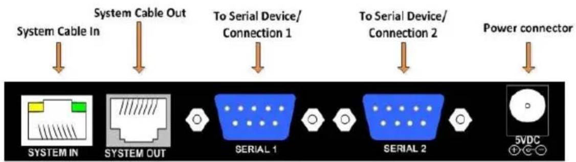
3.4 Receiver DCL
The receiver DCL (Dual Cascade Long) P/N 0VS50006 has the following features:
- Connects to 2 monitors with each having separate video, audio and serial control
- Receiver DCL is cascadable – it has a pass-through port for connecting more receivers/ receivers L/ receivers DCL/ line splitter L
- Can be up to 300m (1,000ft) from a transmitter/broadcaster
- With a line splitter L, can be up to 600m (2000ft) from a transmitter/broadcaster
Notes:
- Dual cascade unit tuning feature influences the VIDEO 1 and VIDEO 2 outputs only, not the SYS OUT port.
Figure 6 illustrates the receiver DCL ports.
flowchart
graph TD
    A["System Cable In"] --> B["System Cable Out"]
    B --> C["To Serial Device/Connection 1"]
    C --> D["To Serial Device/Connection 2"]
    D --> E["Power connector"]
    F["SYSTEM IN"] --> G["SYSTEM OUT"]
    G --> H["SERIAL 1"]
    H --> I["SERIAL 2"]
    I --> J["5VDC"]
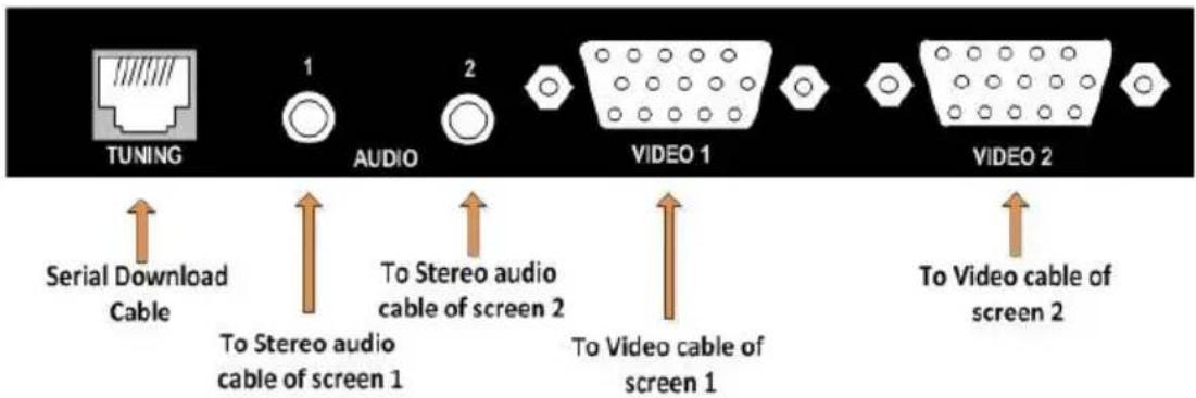
text_image
TUNING 1 AUDIO 2 VIDEO 1 VIDEO 2 Serial Download Cable To Stereo audio cable of screen 1 To Stereo audio cable of screen 2 To Video cable of screen 1 To Video cable of screen 2Figure 6: Receiver DCL Front and Back Connections
3.5 Line Splitter Long
Add line splitters L(ong) to use for clusters or to increase the number of receivers in the system. There is an option to cascade line splitters to line splitters. Figure 7 illustrates the line splitter L ports.
Notes: The last cascaded line splitter long must not be more than 300m (1000ft) from the transmitter or broadcaster.
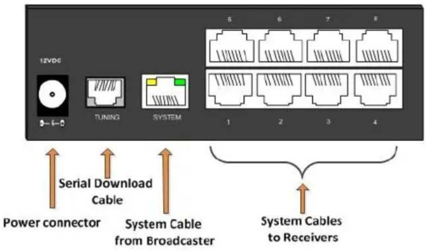
text_image
12VDC TUNING SYSTEM 5 6 7 8 1 2 3 4 Power connector Serial Download Cable System Cable from Broadcaster System Cables to ReceiversFigure 7: Line Splitter Long
3.6 LEDs
This table explains the functions of all the LEDs of the units in the system.
| Unit | LED | Function |
| Transmitter / Broadcaster | Front panel - green | Green - power indicatorYellow – link indication |
| Receiver / Receiver L | RJ-45 system port - green /yellow | Green - power indicatorYellow – link indication, unit is connected to the system this LED flashes from time to timeYellow flashing constantly – Bi-directionalRS-232 communication (only possible with one receiver /receiver L at a time) |
| Receiver DCL | RJ-45 system port - green /yellow | Green - power indicatorYellow flashing – link indication |
| Line Splitter L | Rear panel – RJ-45 system port - green /yellow | Green - power indicatorYellow flashing – link indication |
4 Connecting the DS Vision® 3000
Figure 8 illustrates a sample configuration and its connections.

flowchart
graph TD
    A["Local screen"] -->|To Sets in| B["DS Vision 3000 Broadcaster 16"]
    B -->|To Local Screen| C["Line Splitter"]
    C -->|CATX cables to Receivers/Line splitters| D["Receiver long"]
    C -->|CATX cables to Receivers/Line splitters| E["Video Adjusting unit / Remote Tuning"]
    C -->|CATX cable 1m - 300m to Receiver long unit| F["Receiver long"]
    C -->|To Video in / Speakers| G["Remote screen"]
    C -->|To Audio in / Device| H["Player and Control computer"]
    C -->|To Serial in port| I["Serial Download cable"]
    C -->|To Audio line out port| J["Line out port"]
    C --> K["To Video in port"]
    style A fill:#f9f,stroke:#333
    style B fill:#ccf,stroke:#333
    style C fill:#cfc,stroke:#333
    style D fill:#fcc,stroke:#333
    style E fill:#cff,stroke:#333
    style F fill:#ffc,stroke:#333
    style G fill:#cfc,stroke:#333
    style H fill:#fcc,stroke:#333
    style I fill:#f9f,stroke:#333
    style J fill:#ccf,stroke:#333
    style K fill:#cfc,stroke:#333
Figure 8: Connection Diagram
4.1 Broadcaster/Transmitter Connections
- Connect the broadcaster/transmitter Video In port to the computer's video card with a video cable.
- Connect the broadcaster/transmitter Serial In port to the computer's serial port with a serial extender cable.
- Connect the broadcaster/transmitter Audio In port to the computer's line out port with a stereo audio cable.
- To use the Video Service Utility, connect the broadcaster/transmitter control port and the computer's serial port with a serial download cable.
- (Optional) Connect a monitor to the broadcaster/transmitter Video Out port.
4.2 Receiver/Receiver L Connections
- Connect the screen to the video port.
- Connect the audio/speakers to the audio port.
Note: if you are connecting the audio out of the receivers to speakers they must have an internal amplifier. The audio out is a line out extension of the player. - Where relevant connect the serial connection to the serial port.
4.3 Receiver DCL Connections
- Connect one screen to video port 1 and another screen to video port 2.
- Connect the audio/speakers of the first screen to stereo audio port 1 and connect the audio/speakers of the second screen to stereo audio port 2. Ensure that the video and audio ports are connected to the same numbers, i.e. one screen to video and audio ports 1 and the other screen to video and audio ports 2.
- Where relevant connect the serial connection to the serial ports 1 and/or 2.
4.4 Connecting CATx Cables
Connect the CATx cables as follows.
4.4.1 Connecting the Broadcaster/Transmitter
- Connect CATx cables to the system ports of the broadcaster/transmitter and the system In ports of receivers/L/DCL or line splitter L.
4.4.2 Connecting/Cascading a Line Splitter Long
- Connect CATx cables to the system out ports of the line splitter long and the system in ports of receivers/L/DCL or further line splitters Long.
4.4.3 Cascading a Receiver DCL
- Connect a CATx cable to the system out port of the receiver DCL and the system in port of a receiver/L/DCL or line splitter long.
4.5 Connecting to the Power Supply
- Connect the transmitter/broadcaster and all receiver and line splitter long units to the power supply using the AC/DC adapters provided with the products.
Once the system is connected the DS Vision® 3000 system broadcasts to all remote monitors/speakers.
4.6 Adjusting the Picture Quality
When the broadcasted picture needs adjusting:
- The receiver (version 3)/ receiver L/ receiver DCL/ line splitter long can be tuned either via the service utility, or by using the optional tuning unit
Note: Where there are cascaded receivers/ receiver DCL/line splitters long you must tune them from the unit nearest the broadcaster/transmitter onwards.
4.7 Note on Serial Extension:
The serial connection requires two cables: from player to a transmitter or broadcaster, use a straight serial cable; from receiver to screen, use a cross cable.
5 Technical Specifications
| RESOLUTION: | Up to 1920x1440 @60Hz (depending on cable length) |
| I/O VIDEO SIGNALS: | Analog red, green, blue, 75Ω 0.7Vpp |
| SYNC: | TTL compatible |
| HORIZONTAL/VERTICAL SYNC: | Positive/negative |
| SYSTEM CABLE: | CAT 5/5e/6/7 UTP/FTP cable, 2x4x24AWG solid wire |
| MAX. RANGE: | Receiver short: 110m (360ft),Receiver long: 300m (1000ft),Receiver long with line splitter long: 600m (2000ft)(2 x 300m (1000ft)) |
| SKEW COMPENSATION: | Up to 63nsec |
| DDC: | Complies with VESA DDC-2 specification |
| RS-232 CONNECTION: | Full serial: RXD, TXD, DTR, DSR, RTS, CTS |
| SERIAL BAUD RATE: | Up to 57600 |
| AUDIO: | StereoFrequency response: 20 Hz to 20 kHz, +/-1 dB.Signal-to-Noise Ratio (SNR): 80 dBA.Total Harmonic Distortion and Noise (THD+N):0.017%.Stereo crosstalk: -70 dB.Input impedance: 10kΩ.Line level output; supports multimedia speakers.Maximum I/O levels: 3.1Vpp (line level). |
| SERIAL: | Broadcaster / Transmitter – DCERceivers - DTE |
| OPERATING TEMPERATURE: | 5°C to 40°C (41°F to 104°F) |
| STORAGE TEMPERATURE: | -40°C to 70°C (-104°F to 158°F) |
| WARRANTY: | 3 years |
| Specifications are subject to change without notice at http://www.kramerelectronics.com | |
LIMITED WARRANTY
The warranty obligations of Kramer Electronics for this product are limited to the terms set forth below:
What is Covered
This limited warranty covers defects in materials and workmanship in this product.
What is Not Covered
This limited warranty does not cover any damage, deterioration or malfunction resulting from any alteration, modification, improper or unreasonable use or maintenance, misuse, abuse, accident, neglect, exposure to excess moisture, fire, improper packing and shipping (such claims must be presented to the carrier), lightning, power surges, or other acts of nature. This limited warranty does not cover any damage, deterioration or malfunction resulting from the installation or removal of this product from any installation, any unauthorized tampering with this product, any repairs attempted by anyone unauthorized by Kramer Electronics to make such repairs, or any other cause which does not relate directly to a defect in materials and/or workmanship of this product. This limited warranty does not cover cartons, equipment enclosures, cables or accessories used in conjunction with this product.
Without limiting any other exclusion herein, Kramer Electronics does not warrant that the product covered hereby, including, without limitation, the technology and/or integrated circuit(s) included in the product, will not become obsolete or that such items are or will remain compatible with any other product or technology with which the product may be used.
How Long Does this Coverage Last
Three years as of this printing; please check our Web site for the most current and accurate warranty information.
Who is Covered
Only the original purchaser of this product is covered under this limited warranty. This limited warranty is not transferable to subsequent purchasers or owners of this product.
What Kramer Electronics will do
Kramer Electronics will, at its sole option, provide one of the following three remedies to whatever extent it shall deem necessary to satisfy a proper claim under this limited warranty:
- Elect to repair or facilitate the repair of any defective parts within a reasonable period of time, free of any charge for the necessary parts and labor to complete the repair and restore this product to its proper operating condition. Kramer Electronics will also pay the shipping costs necessary to return this product once the repair is complete.
- Replace this product with a direct replacement or with a similar product deemed by Kramer Electronics to perform substantially the same function as the original product.
- Issue a refund of the original purchase price less depreciation to be determined based on the age of the product at the time remedy is sought under this limited warranty.
What Kramer Electronics will not do Under This Limited Warranty
If this product is returned to Kramer Electronics or the authorized dealer from which it was purchased or any other party authorized to repair Kramer Electronics products, this product must be insured during shipment, with the insurance and shipping charges prepaid by you. If this product is returned uninsured, you assume all risks of loss or damage during shipment. Kramer Electronics will not be responsible for any costs related to the removal or re-installation of this product from or into any installation. Kramer Electronics will not be responsible for any costs related to any setting up this product, any adjustment of user controls or any programming required for a specific installation of this product.
How to Obtain a Remedy under this Limited Warranty
To obtain a remedy under this limited warranty, you must contact either the authorized Kramer Electronics reseller from whom you purchased this product or the Kramer Electronics office nearest you. For a list of authorized Kramer Electronics resellers and/or Kramer Electronics authorized service providers, please visit our web site at www.kramerelectronics.com or contact the Kramer Electronics office nearest you.
In order to pursue any remedy under this limited warranty, you must possess an original, dated receipt as proof of purchase from an authorized Kramer Electronics reseller. If this product is returned under this limited warranty, a return authorization number, obtained from Kramer Electronics, will be required. You may also be directed to an authorized reseller or a person authorized by Kramer Electronics to repair the product.
If it is decided that this product should be returned directly to Kramer Electronics, this product should be properly packed, preferably in the original carton, for shipping. Cartons not bearing a return authorization number will be refused.
Limitation on Liability
THE MAXIMUM LIABILITY OF KRAMER ELECTRONICS UNDER THIS LIMITED WARRANTY SHALL NOT EXCEED THE ACTUAL PURCHASE PRICE PAID FOR THE PRODUCT. TO THE MAXIMUM EXTENT PERMITTED BY LAW, KRAMER ELECTRONICS IS NOT RESPONSIBLE FOR DIRECT, SPECIAL, INCIDENTAL OR CONSEQUENTIAL DAMAGES RESULTING FROM ANY BREACH OF WARRANTY OR CONDITION, OR UNDER ANY OTHER LEGAL THEORY. Some countries, districts or states do not allow the exclusion or limitation of relief, special, incidental, consequential or indirect damages, or the limitation of liability to specified amounts, so the above limitations or exclusions may not apply to you.
Exclusive Remedy
TO THE MAXIMUM EXTENT PERMITTED BY LAW, THIS LIMITED WARRANTY AND THE REMEDIES SET FORTH ABOVE ARE EXCLUSIVE AND IN LIEU OF ALL OTHER WARRANTIES, REMEDIES AND CONDITIONS, WHETHER ORAL OR WRITTEN, EXPRESS OR IMPLIED. TO THE MAXIMUM EXTENT PERMITTED BY LAW, KRAMER ELECTRONICS SPECIFICALLY DISCLAIMS ANY AND ALL IMPLIED WARRANTIES, INCLUDING, WITHOUT LIMITATION, WARRANTIES OF MERCHANTABILITY AND FITNESS FOR A PARTICULAR PURPOSE. IF KRAMER ELECTRONICS CANNOT LAWFULLY DISCLAIM OR EXCLUDE IMPLIED WARRANTIES UNDER APPLICABLE LAW, THEN ALL IMPLIED WARRANTIES COVERING THIS PRODUCT, INCLUDING WARRANTIES OF MERCHANTABILITY AND FITNESS FOR A PARTICULAR PURPOSE, SHALL APPLY TO THIS PRODUCT AS PROVIDED UNDER APPLICABLE LAW. IF ANY PRODUCT TO WHICH THIS LIMITED WARRANTY APPLIES IS A 'CONSUMER PRODUCT' UNDER THE MAGNUSON-MOSS WARRANTY ACT (15 U.S.C.A. §2301, ET SEQ.) OR OTHER APPLICABLE LAW, THE FOREGOING DISCLAIMER OF IMPLIED WARRANTIES SHALL NOT APPLY TO YOU, AND ALL IMPLIED WARRANTIES ON THIS PRODUCT, INCLUDING WARRANTIES OF MERCHANTABILITY AND FITNESS FOR THE PARTICULAR PURPOSE, SHALL APPLY AS PROVIDED UNDER APPLICABLE LAW.
Other Conditions
This limited warranty gives you specific legal rights, and you may have other rights which vary from country to country or state to state.
This limited warranty is void if (i) the label bearing the serial number of this product has been removed or defaced, (ii) the product is not distributed by Kramer Electronics or (iii) this product is not purchased from an authorized Kramer Electronics reseller. If you are unsure whether a reseller is an authorized Kramer Electronics reseller, please visit our Web site at www.kramerelectronics.com or contact a Kramer Electronics office from the list at the end of this document.
Your rights under this limited warranty are not diminished if you do not complete and return the product registration form or complete and submit the online product registration form. Kramer Electronics thanks you for purchasing a Kramer Electronics product. We hope it will give you years of satisfaction.

For the latest information on our products and a list of Kramer distributors, visit our Web site where updates to this user manual may be found.
We welcome your questions, comments, and feedback.
Web site: www.kramerelectronics.com
E-mail: info@kramerel.com


SAFETY WARNING
Disconnect the unit from the power supply before opening and servicing

P/N: 2900-300282

Rev: 2