WS6028 - Washing machine Amer - Free user manual and instructions
Find the device manual for free WS6028 Amer in PDF.

User questions about WS6028 Amer
0 question about this device. Answer the ones you know or ask your own.
Ask a new question about this device
Download the instructions for your Washing machine in PDF format for free! Find your manual WS6028 - Amer and take your electronic device back in hand. On this page are published all the documents necessary for the use of your device. WS6028 by Amer.
USER MANUAL WS6028 Amer
5.2.1 Authentication Mode of Open....5-1
5.2.2 Authentication Mode of Static WEP 5-2
5.2.3 WEP 802.1x ....5-2
5.2.4 WPA Personal ....5-3
5.2.5 WPA Enterprise ....5-3
5.3 CONFIGURE VLAN....5-4
5.4 MAC AUTHENTICATION....5-4
5.5 ENABLE DIST-TUNNEL MODE....5-5
5.6 CLIENT QoS....5-5
CHAPTER 6 AP MANAGEMENT ......6-1
6.1 ADD/MODIFY/DELETE AP GROUP....6-1
6.1.1 Normal Attribute....6-1
6.1.2 AP Config 6-2
6.1.3 Radio 6-2
6.1.4 VAP 6-3
6.1.5 QoS 6-4
6.1.6 TSPEC 6-5
6.2 COPY AP GROUP 6-5
6.3 APPLY AP GROUP 6-6
CHAPTER 7 SECURITY AUTHENTICATION .... 7-1
7.1 RADIUS CONFIGURATION....7-1
7.1.1 Global Configuration 7-1
7.1.2 Radius Authentication Server Configuration....7-2
7.1.3 Radius Accounting Server Configuration ....7-2
7.1.4 Radius Group Manage....7-2
7.1.5 Radius Configuration 7-3
7.2 LDAP CONFIGURATION 7-3
CHAPTER 8 DISCOVERY 8-1
8.1 L3/IP DISCOVERY ....8-1
8.1.1 Enable/Disable L3/IP Discovery....8-1
8.1.2 Add IP of L3/IP Discovery....8-1
8.1.3 Delete IP Address from L3/IP Discovery List ....8-1
8.2 L2/VLAN DISCOVERY....8-1
8.2.1 Enable L2/VLAN Discovery....8-1
8.2.2 Add VLAN of L2/VLAN Discovery....8-2
8.2.3 Delete VLAN from L2/VLAN Discovery List ....8-2
CHAPTER 9 PROVISIONING ......9-1
9.1 AP PROVISIONING....9-1
9.2 SWITCH PROVISIONING 9-2
9.3 MUTUAL AUTHENTICATION....9-2
CHAPTER 10 WIDS SECURITY.... 10-1
10.1 AP CONFIGURATION....10-1
10.2 CLIENT CONFIGURATION....10-2
10.3 KNOWN CLIENT....10-3
10.3.1 MAC Authentication Mode 10-3
10.3.2 Black/white List Configuration 10-3
CHAPTER 11 CAPTIVE PORTAL.... 11-1
11.1 GLOBAL CONFIGURATION....11-1
11.2 CAPTIVE PORTAL AUTHENTICATION TYPE....11-1
11.3 PORTAL SERVER CONFIGURATION....11-1
11.4 FREE RESOURCE CONFIGURATION....11-2
11.5 MAC PORTAL CONFIGURATION 11-3
11.6 PORTAL INSTANCE CONFIGURATION....11-3
CHAPTER 12 CONFIG PUSH 12-1
12.1 CONFIG PUSH....12-1
12.2 CONFIG PUSH OPTION ....12-1
CHAPTER 13 AP IMAGE UPGRADING .... 13-1
13.1 AP IMAGE AUTO UPGRADE....13-1
13.2 AP MANUAL UPGRADE CONFIGURATION....13-1
CHAPTER 14 LOAD BALANCE.... 14-1
14.1 CREATE TEMPLATE....14-1
14.2 AP PROFILE ASSOCIATED LOAD BALANCE TEMPLATE....14-1
14.3 DELETE LOAD BALANCE TEMPLATE 14-2
CHAPTER 15 TIME LIMIT POLICY 15-1
15.1 NETWORK TIMELIMIT CONFIGURATION....15-1
15.2 RADIO TIME LIMIT CONFIGURATION ....15-2
CHAPTER 16 ORGANIZATION UNIQUE IDENTIFIER (OUI) 16-1
16.1 ADD OUI 16-1
16.2 DELETE OUI 16-1
CHAPTER 17 TRAP AND SYSLOG 17-1
17.1 SNMP TRAPS....17-1
17.1.1 Wireless Global Traps.... 17-1
17.1.2 Captive Portal 17-2
17.2 SYSLOG CONFIGURATION ....17-2
17.2.1 Wireless Syslog Configuration.... 17-2
17.2.2 Captive Portal Syslog Configuration 17-2
CHAPTER 18 MONITOR 18-1
18.1 AC....18-1
18.1.1 Cluster.... 18-1
18.1.2 Each AC Status/Statistics.... 18-5
18.2 AP 18-8
18.2.1 Basic AP Information.... 18-8
18.2.2 AP Detail.... 18-9
18.2.3 Failure AP List 18-12
18.3 WIRELESS CLIENT....18-12
18.3.1 Associated Client List.... 18-12
18.3.2 Associated Client Detail 18-13
18.3.3 Detected Client List 18-14
18.3.4 Detected Client Detail 18-15
18.4 RF SCAN....18-17
18.4.1 AP RF Scan Status 18-17
18.4.2 AP RF Scan Detail 18-17
18.4.3 Client Dynamic Blacklist 18-19
CHAPTER 19 MANAGEMENT .... 19-1
19.1 BASIC CONFIGURATION....19-1
19.1.1 Login Username and Password Configuration 19-1
19.1.2 Login User Authentication Method Configuration 19-2
19.1.3 Login User Security IP Set 19-3
19.1.4 Basic Configuration.... 19-3
19.1.5 Save Current Running-configuration.... 19-4
19.2 SNMP CONFIGURATION....19-5
19.2.1 SNMP Authentication.... 19-5
19.2.2 SNMP Management.... 19-8
19.2.3 Community Managers 19-8
19.2.4 Configure SNMP Manager Security IP.... 19-9
19.2.5 SNMP Statistics 19-9
19.3 SSH MANAGEMENT ....19-10
19.3.1 Switch on-off SSH.... 19-10
19.3.2 SSH Management.... 19-10
19.4 FIRMWARE UPDATE ....19-11
19.4.1 TFTP Client Service 19-12
19.4.2 TFTP Server Service 19-13
19.4.3 FTP Client Service.... 19-14
19.4.4 FTP Server Service 19-15
19.5 TELNET SERVER CONFIGURATION ....19-16
19.5.1 Telnet Server State.... 19-16
19.5.2 Max Numbers of Telnet Access Connection.... 19-16
19.6 MAINTENANCE AND DEBUGGING COMMAND ....19-16
19.6.1 Debug Command 19-17
19.6.2 Others.... 19-18
Chapter 1 Web Management
The WS6028 or Access Controller / AC is managed using the build in web gui. This section will cover the process of getting connected to the device.
1.1 Configuration Preparation
To configure the AC, we recommend a stand-alone pc and a direct connection to the device.
1.1.1 AC Management through Web
Configure the AC by using a PC configured to be in the same subnet. The default IP address of AC is 192.168.1.1 and the subnet mask is 255.255.255.0.
The steps of creating the network connection are as below:
Step 1: setting up the environment:

text_image
Connect with cablesFig 1-1 Web Management Configuration Environment
As shown above, the Ethernet port for the PC is connected with the AC's Ethernet Port 1 by a network cable
Step 2: Setting the network connection (for example with Windows XP system):
After connecting successfully, please click the
text_image
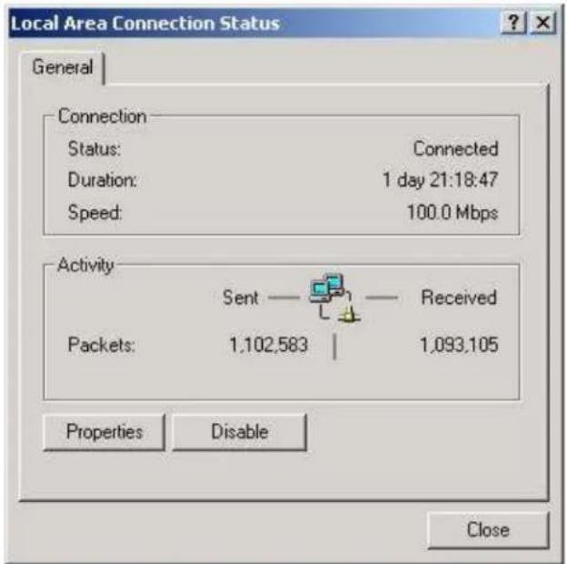
Local Area Connection Status General Connection Status: Connected Duration: 1 day 21:18:47 Speed: 100.0 Mbps Activity Sent — Received Packets: 1,102,583 | 1,093,105 Properties Disable CloseFig 1-2 Local Area Connection Status
(1) Click the

text_image
Local Area Connection Properties General | Sharing | Connect using: Realtek RTL8139(A) PCI Fast Ethernet Adapter Configure Components checked are used by this connection: ✓ Client for Microsoft Networks ✓ File and Printer Sharing for Microsoft Networks ✓ Internet Protocol (TCP/IP) Install... Uninstall Properties Description Allows your computer to access resources on a Microsoft network. ✓ Show icon in taskbar when connected OK CancelFig 1-3 Local Area Connection Properties
(2) Select "Internet Protocol (TCP/IP)", and then click the

text_image
Internet Protocol (TCP/IP) Properties General You can get IP settings assigned automatically if your network supports this capability. Otherwise, you need to ask your network administrator for the appropriate IP settings. Obtain an IP address automatically Use the following IP address: IP address: 192 . 168 . 1 . 2 Subnet mask: 255 . 255 . 255 . 0 Default gateway: . Obtain DNS server address automatically Use the following DNS server addresses: Preferred DNS server: . Alternate DNS server: . Advanced... OK CancelFig 1-4 Internet Protocol (TCP/IP) Properties
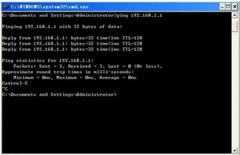
Step 3: Use the PING command to ensure the connection status between PC and AC.Click the

text_image
Run Type the name of a program, folder, document, or Internet resource, and Windows will open it for you. Open: OK Cancel Browse...Fig 1-5 Run dialog box
Input "CMD", and click the
text_image
C:\Documents and Settings\Administrator>ping 192.168.1.1 Pinging 192.168.1.1 with 32 bytes of data: Reply from 192.168.1.1: bytes=32 time<1ms TTL=128 Reply from 192.168.1.1: bytes=32 time<1ms TTL=128 Reply from 192.168.1.1: bytes=32 time<1ms TTL=128 Ping statistics for 192.168.1.1: Packets: Sent = 3, Received = 3, Lost = 0 (0% loss), Approximate round trip times in milli-seconds: Minimum = 0ms, Maximum = 0ms, Average = 0ms Control-C ^C C:\Documents and Settings\Administrator>Fig 1-6 Dialog box for command lines
1.2 Web Interface Introduction
1.2.1 Login AC Switch
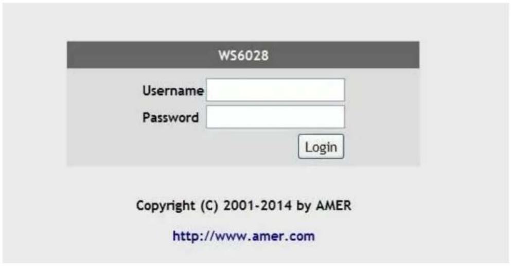
Run the Web browser; use the default IP address of 192.168.1.1 in the address bar, and press the
text_image
WS6028 Username Password Login Copyright (C) 2001-2014 by AMER http://www.amer.comFig 1-7 Logon page layout
1.2.2 Web Interface Introduction
Enter the Web configuration interface after successful logging in the AC. The "dashboard" will be enabled as default. The basic information of the current AC and the managed AP status will be shown in the dashboard. The detailed introduction of the dashboard can be viewed in chapter 2 of this manual.
On the top, is the main menu of each function module. Click the corresponding menu to configure the wireless or wired functions.

text_image
amcr networks Dashboard WLAN Configuration Monitor Management Wired Configuration System Info Name WS6028 IP Address 192.168.1.1 MAC Address 00-03-0f-3f-4f-ee System Uptime 0 weeks, 0 days, 0 hours, 3 minutes Maximum Managed APs 32 S/N GOSWE310ES08840020 Version 7.0.3.5(R0035.0097) Device Info Managed APs 0 Authenticated Clients Managed AP MAC Address (*)-Peer Managed Location IP Address Profile Software Version Status Support Company Amer Networks Hotline 800-810-9119 WWW http://www.amer.comFig 1-8 Web configuration page layout
1.2.3 Menu Introduction
The following is a breakdown of the Options in the web gui, and there sub menus.
| Menu | Page | |
| Dashboard | ||
| WLAN configuration | Fast config | |
| System config | ||
| Network | ||
| AP Group management | ||
| Security authentication | ||
| Discovery | ||
| Provisioning | ||
| WIDS security | ||
| Captive Portal | ||
| Advanced config | Config push | |
| AP image upgrade | ||
| Load balance | ||
| Data transfer | ||
| Time limit policy | ||
| Organization unique identifier (OUI) | ||
| Trap and syslog | ||
| Monitor | AC | |
| AP | ||
| Wireless client | ||
| RF scan | ||
| Management | Switch basic configuration | Login user configuration |
| Login user authentication method configuration | ||
| Login user security IP management | ||
| Basic configuration | ||
| Save current running-configuration | ||
| SNMP configuration | SNMP authentication | |
| SNMP management | ||
| Community managers | ||
| Configure snmp manager security IP | ||
| SNMP statistics | ||
| management | Switch on-off SSH SSH | |
| SSH management | ||
| upgrade | TFTP service Firmware | |
| FTP service | ||
| Telnet server configuration | Telnet server state | |
| Max numbers of Telnet access connection | ||
| Maintenance and debugging command | Debug command | |
| show clock | ||
| show cpu usage | ||
| show memory usage | ||
| show flash | ||
| show running-config | ||
| show switchport interface | ||
| show tcp | ||
| show udp | ||
| show telnet login | ||
| show version | ||
1.2.4 AC Web Exiting Function
Click the
Chapter 2 Dashboard
The dashboard includes four parts; system info, managed access point, device info and the support info.
2.1 System Info
The system info for the wireless AC is as below:
| System Info | |
| Name | WS6028 |
| IP Address | 192.168.1.1 |
| MAC Address | 00-03-0f-3f-4f-ee |
| System Uptime | 0 weeks, 0 days, 0 hours, 3 minutes |
| Maximum Managed APs | 32 |
| S/N | GOSWE310E508840020 |
| Version | 7.0.3.5(R0035.0097) |
The information in the figure is:
■ Name: the name of AC
- IP address: the URL address of accessing the AC is 192.168.1.1
■ MAC address: the mac address of AC is 00-03-0f-11-20-50
- System uptime: the normal running time: 1day, 4 hours and 2 minutes
■ Maximum managed APs: 16
S/N: 111111
■ Version: 7.0.3.5 (R0035.0088)
- : click this icon to refresh the current module.
2.2 Managed Access Point
The managed access point shows the AP information including the MAC address, location, IP address, profile, software version, status, configuration status and age of AP.

text_image
Managed Access Points MAC Address (*)-Peer Managed Location IP Address Profile Software Version Status Configuration Status Age 00-03-0f-03-66-00 10.0.0.4 1-Default 2.0.3.39 managed success 0d:00:00:01■ MAC address: the mac address of AP
■ Location: show the location of AP.
■ IP address: the address of AP.
■ Profile: the profile that the AP belongs to
■ Software version: the version of AP.
■ Status: the current management status of AP.
- Configuration status: show the current configuration status of AP.
■ Age: the management AP age.
Click the MAC address of AP to jump to the detailed AP list page of the monitor page.
2.3 Device Info
There are two points: Display the total numbers of the managed APs and authenticated clients in cluster.

text_image
Device Info Managed APs 1 Authenticated Clients 12.4 Support
This section provides the company's name, phone number and the website as below:
| Support | |
| Company | Amer Networks |
| Hotline | 888-501-9971 |
| WWW | http://www.amer.com |
Chapter 3 Fast Config
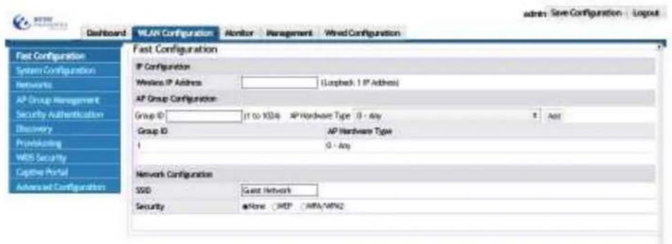
Click "WLAN configuration->Fast Config" to configure the WLAN function quickly, including WLAN managed IP address, AP groups and the basic network configuration;. This configuration will then be sent to all connect AC in the network.
Notice: This fast config is used for the simple configuration or a quick start wizard. If the AC has any previous configuration on it, it will be replaced with the fast config.
text_image
Fast Configuration IP Configuration Wireless IP Address: (Locked 1 IP Address) AP Group Configuration: Group ID: (1 to XSD) AP Hardware Type 0 - Any Group ID: AP Hardware Type 1 0 - Any Network Configuration SSID Guest Network Security asNone MSP AFA/AMN2 admin Save Configuration | Logout3.1 IP Config
To configure the management IP address for the AC. Input the wireless IP address to be configured in the box and click the "submit" button. The input IP address will be configured as the wireless IP address.

text_image
IP Config Wireless IP Address 192.168.1.254 (Loopback 1 IP address)3.2 AP Group Config
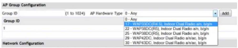
The AP group config can add and update the ID and hardware type of the AP in the group.
Example: Input 17 in the ID box, select 17- WAP33DC, Indoor Dual Radio a/n, b/g/n as the corresponding AP hardware type; and then click "add" to add them into the table. Click "submit" to submit them to AC.
Notice: Click the "submit" button, and the configuration will be applied on the AC. Any modifications will be lost if the submit button is not selected.
text_image
AP Group Configuration Group ID (1 to 1024) AP Hardware Type 0 - Any Group ID 1 Network Configuration 0 - Any 17 - WAP33DC(R4.5), Indoor Dual Radio a/n, b/g/n 22 - WAP38DC(R5), Indoor Dual Radio a/n, b/g/n 25 - WAP38DC(R5), Indoor Dual Radio a/n, b/g/n 29 - WAP42DC, Indoor Dual Radio a/n/ac, b/g/n 30 - WAP43DC, Indoor Dual Radio a/n/ac, b/g/n3.3 Network Config
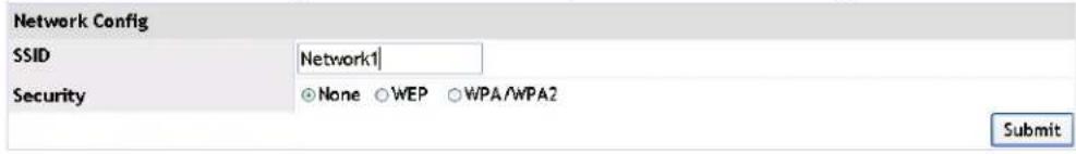
The network config will setup and configure the 1^st SSID for all connected AP, within the same group ID.
3.3.1 SSID
The SSID represents the service set identifier, used to name a wireless network. The SSID can divide one large WLAN into subnets which authentication; and only the user who knows the password can enter into the corresponding subnet. It can prevent unwanted users or access on the network.
Example: Input the name of the network in the SSID box, such as Network1 and select "none" for security; click "submit" to complete the network configuration.
text_image
Network Config SSID Network1 Security None WEP WPA/WPA2 Submit3.3.2 Security
The security option in the network configuration can configure the access control for the SSID. The methods of authentication include: static WEP, WEP 802.1X, WPA/WPA2 Personal and WPA/WPA2 Enterprise.
3.3.2.1 WEP Mode
Choose WEP through the security option for the network config. Under WEP, there are two kinds of authentication methods, WEP and WEP 802.1X. Static WEP, is same process as the configuration of "WLAN configuration->Network Config" and it is shown in more detail in chapter 5 networks.
Select the "WEP IEEE802.1X" to fast configure a radius server setup.
Example: Configure RADIUS as RadiusServer and input the authentication host address and accounting host address: 192.168.1.100. Configure the shared RADIUS
server key as test and click "submit" to complete the WEP 802.1X configuration.
Notice: Only the RADIUS authentication and accounting server without any configuration can be configured in the fast config. If they have already been configured, they cannot be deleted or modified in the fast config. The RADIUS configuration is viewed in chapter 7 security authentication configuration.

text_image
Network Config SSID Network1 Security None WEP WPA/WPA2 Static WEP WEP IEEE802.1x Radius Config Radius Group Name RadiusServer Radius Authentication Host Address 192.168.1.100 Radius Accounting Host Address 192.168.1.100 Radius Server Key test Submit3.3.2.2 WPA/WPA2
Select the WPA/WPA2 option to configure the WPA/WPA2 authentication. There are two kinds of authentication methods, WPA personal and WPA enterprise.
The configuration of WPA personal is same as the "WLAN configuration->WPA personal" and it is shown in more detail in chapter 5 networks.
The configuration of WPA enterprise is same as WEP 802.1X. Select the "WPA enterprise" button to set the configuration.
Example: Configure RADIUS as RadiusServer and input the authentication host address and accounting host address: 192.168.1.100. Configure the shared RADIUS server key as test and click "submit" to complete the WPA enterprise configuration.
Notice: Only the RADIUS authentication and accounting server without any configuration can be configured in the fast config. If they have already been configured, they cannot be deleted or modified in the fast config. The RADIUS configuration is viewed in chapter 7 security authentication configuration.
Chapter 4 System Config
Click "WLAN configuration->System config" to view the system config page. In this section, the parameters under the WLAN global mode can be configured.

text_image
amor networks Dashboard WLAN Configuration Monitor Management Wired Configuration Fast Configuration System Configuration Networks AP Group Management Security Authentication Discovery Provisioning WIDS Security Captive Portal Advanced Configuration System Configuration WLAN Enable Auto IP Assign Mode IPv4 Address IPv6 Address AP Authentication Mode AP Validation Method Radius Authentication Server Radius Accounting Mode Client-QoS Global Mode Country Code Peer Group ID Cluster Priority MAC Configure AP Database on AP Group Management Page Default-RADIUS-Server CA - Canada (1-255) (0-255)4.1 WLAN Enable
Select the option for "WLAN enable" to enable the WLAN function. The WLAN service of the AC only can be used after select this option; if unchecked, all WLAN function on the AC will be disabled and the WLAN service will be stopped.
System Config
Wlan Enable

4.2 Auto IP Assign Mode
Select the option for "Auto IP Assign Mode" to make the WLAN function of the AC select its IPv4 address automatically from a DHCP server.
When enabled the automatic assignment function will appoint an IP address for the WLAN automatically. The basis is: if there are any loopback interfaces on AC, choose the IP address of the interface with the minimum loopback index number as the address for the WLAN function. If there are any L3 interfaces, choose the minimum IP address for the L3 interfaces as the address for the WLAN function.
Auto IP Assign Mode

IP Address
192.2.2.2
Uncheck this box to disable the auto IP assign mode. Then configure a static IP address manually for the WLAN IP address of AC. When configuring the static IP, the address of any existed loopback or L3 interfaces should be used, otherwise, it may not be effective and the WLAN function won't work normally.
Auto IP Assign Mode
AC Static IP Address
IP Address

17.16.1.10
17.16.1.10
4.3 AP Authentication Mode
There are 3 modes of AP authentication. The MAC address mode is the default.
AP Authentication Mode
AP Validation Method

"None" means the automatic registration authentication mode. The AP database is not required to be added manually into the AC, it will join a cluster when the AC or AP discovers the other side.
"MAC" means the MAC address authentication mode. The ap database needs to be entered manually, and then an AP can join the cluster.
"Password" means the password authentication mode. After the connection is made between the AP and the AC, they can both join the cluster using the password authentication.
4.4 AP Validation Method
With the "MAC" option for the AP authentication mode, the AP validation method must be configured. This option allows the AP to use local authentication or RADIUS server authentication for the AP authentication.
The local authentication is the default. The authentication method can be changed to RADIUS server authentication by selecting the parameter to be "radius".
AP Authentication Mode
AP Validation Method
Radius Authentication Server

Selecting "Radius" for the AP authentication method, the user needs to choose a server name from the RADIUS server group list (it should be configured first and it is shown in chapter 7 security authentication), and the authentication request will be sent to the selected RADIUS server.
AP Authentication Mode
AP Validation Method


Config Radius Server
4.5 Radius Authentication Server
Configure the radius authentication server by entering the server name below:
Radius Authentication Server
radius
4.6 Radius Accounting Mode
Select the single box to enable the radius accounting function as below:
Radius Accounting Mode

4.7 Radius Accounting Server
Configure the radius accounting server by entering the server name as below:
Radius Accounting Server
radius
4.8 Client-QoS Global Mode
Select this option to enable the global client-QoS function of AC.
The Client-QoS Global Mode is divided into global on-off and current network on-off. Both of them should be enabled, to allow the clients associated with this network, configured ACL, DiffServ, and any rate limit of down/up can be used.
Client-QoS Global Mode

4.9 Country Code
This drop-down box is used to configure the country code of the AC and AP.
The configured country code must match the country that the device is installed in.
Country Code
CA - Canada
4.10 Peer Group ID
The Peer Group ID can be configured through this text box. The ACs with the same Group ID can make up a WLAN cluster and they can transmit information to each other. The ACs with different Group ID cannot communicate with each other.
The default peer group ID is 1 and the range is from 1 to 255.
Peer Group ID
1 (1-255)
4.11 Cluster Priority
The Cluster Priority for the AC can be configured in this section. The larger the value, the higher the priority and the AC can be selected as the master Controller. When changing the priority of one AC in cluster, it will trigger the new selection of a master Controller.
The default cluster priority is 1 and the range is from 0 to 255.
Cluster Priority
1 (0-255)
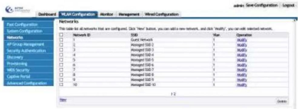
Chapter 5 Networks
5.1 Configure Network ID
16 network ID's are created by default. The user can choose to select the default networks, or create a new network ID.
text_image
Post Configuration System Configuration Networks AP Group Management Security Authentication Discovery Processing Wi-Fi Security Capture Portal Advanced Configuration Networks This table lists all networks that are configured. Click 'New' button, you can add a new network, and click 'Modify', you can add selected network. Network ID SSD Van OPeraion 1 Guest Network 1 Mod3 2 Managed SSD-2 1 Mod3 3 Managed SSD-3 1 Mod3 4 Managed SSD-4 1 Mod3 5 Managed SSD-5 1 Mod3 6 Managed SSD-6 1 Mod3 7 Managed SSD-7 1 Mod3 8 Managed SSD-8 1 Mod3 9 Managed SSD-9 1 Mod3 10 Managed SSD-10 1 Mod3 1/2 Note CancelClick WLAN configuration -> Configuration and choose a network, for example, modify the ssid of network8 as shown below:

text_image
Modify - Managed SSID 8 NetworkID* 8 (1~1024) SSID wlan5.2 Configure Authentication Mode
The network includes multiple kinds of authentication modes as shown below:

text_image
Authentication Mode VLAN MAC Authentication Mode None None Static WEP WEP 802.1x WPA Personal WPA Enterprise (1~4094)5.2.1 Authentication Mode of Open
None means that the authentication mode is open. The corresponding command is security mode none; it states that a user name or password is not required.
5.2.2 Authentication Mode of Static WEP
Static WEP means that the authentication mode is security mode static-wep. When connect to the network, the wep key is needed for association. The WEP authentication mode includes open system and shared key. The WEP key type includes ASCII and HEX. The length includes 64 and 128.
Example: Configure the authentication as open system, the WEP key type is ASCII, the length is 64 and the WEP key is 12345 as below:
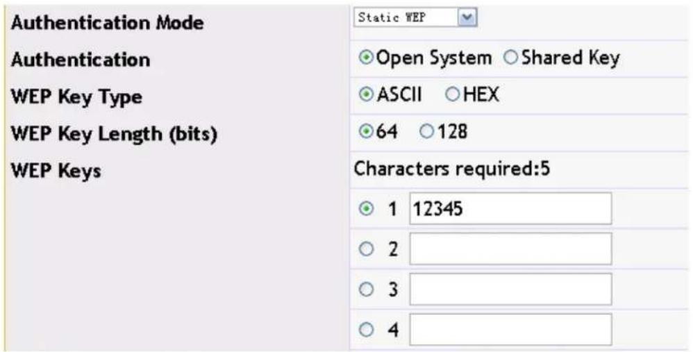
text_image
Authentication Mode Authentication WEP Key Type WEP Key Length (bits) WEP Keys Static WEP Open System Shared Key ASCII HEX 64 128 Characters required:5 1 12345 2 3 45.2.3 WEP 802.1x
The WEP 802.1x corresponds to the command of "security mode wep-dot1x". This authentication mode needs the WEP authentication of a radius server. The radius server configuration is viewed in the radius authentication server configuration in "security". The WEP 802.1x can also configure the radius accounting server and the configuration is viewed in the radius accounting server configuration in "security".
Example: Configure the radius authentication server as the configured wlan1 and configure the radius accounting server as the configured wlan2. The accounting update interval, bcast key refresh rate and the session key refresh rate adopt the default WEP 80.21x authentication as below:
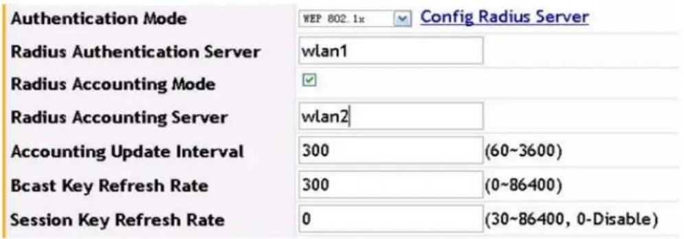
text_image
Authentication Mode WEP 802.1x Config Radius Server Radius Authentication Server wlan1 Radius Accounting Mode ✓ Radius Accounting Server wlan2 Accounting Update Interval 300 (60~3600) Bcast Key Refresh Rate 300 (0~86400) Session Key Refresh Rate 0 (30~86400, 0-Disable)Click the "OK" to save the configuration.
5.2.4 WPA Personal
WPA personal corresponds to the configuration of a network using this security method. Users require the password for associating when connect to the network. There are three modes of WPA, WPA2 and WPA/WPA2 in the WPA personal authentication and there are two WPA ciphers of TKIP and CCMP.
Example: Configure the WPA version as WPA/WPA2 and the WPA cipher as CCMP, WPA key is 12345678, the bcast key refresh rate adopts the default WPA personal authentication mode. Input 12345678 for association when the client connects to this network.

text_image
Authentication Mode WPA Personal WPA Versions WPA/WPA2 WPA Ciphers CCMP WPA Key 12345678 Bcast Key Refresh Rate 300 (0~86400)Click the "OK" to save the configuration.
5.2.5 WPA Enterprise
WPA Enterprise corresponds to the configuration of a network using this security method. It authenticates and accounts using the radius server. The WPA version and cipher in WPA enterprise is the same with the WPA version and cipher in WPA personal; the difference is that in WPA enterprise, the radius server authentication is used. Before the radius server authentication, user can pre-authenticate. Click “pre-authentication” button to enable it. When the client connects, they authenticate through a user name and password configured on the radius server.
Example: Configure the radius authentication server as wlan1, and configure the radius accounting server as wlan2 (the detailed configuration is viewed in the security configuration). The WPA version is WPA/WPA2, WPA cipher is CCMP, the bcast key refresh rate and the session key refresh rate are the default WPA enterprise authentication mode.

text_image
Authentication Mode WPA Enterprises Config Radius Server WPA Versions WPA/WPA2 WPA Ciphers CCMP Radius Authentication Server wlan1 Radius Accounting Mode ✓ Radius Accounting Server wlan2 Accounting Update Interval 300 (60~3600) Pre-Authentication Mode ✓ Pre-Authentication Limit 0 (0~192) Bcast Key Refresh Rate 300 (0~86400) Session Key Refresh Rate 0 (30~86400, 0-Disable)Click the "OK" to save the configuration.
5.3 Configure VLAN
Input the VLAN ID in the VLAN box and then bind it to the network. It is the data VLAN that the client uses.

text_image
VLAN 40 (1~4094)5.4 Mac Authentication
Click the MAC authentication on-off to enable the MAC authentication. The MAC authentication controls the clients to access the network through configuring the black and white list. The black and white list configuration is viewed in the chapter of "WIDS security".

text_image
MAC Authentication Mode ✓ Config Black and White List5.5 Enable Dist-tunnel Mode
Click the dist-tunnel mode on-off button to enable it as below:
Dist-tunnel Mode

5.6 Client QoS
The client QoS controls the rate and access of the client through the network. There are three options: 1. Client QoS bandwidth limit up and down; 2. Client QoS access control up and down; 3. Client QoS DiffServ policy up and down.
Enable the global on-off of client QoS first before using this option. In WLAN configuration→system config, choose the "client-QoS global mode" and apply to enable the global on-off as below:

amer
networks
Dashboard
WLAN Configuration
Monitor
Management
Wired Configuration
Fast Configuration
System Configuration
Networks
AF Group Management
Security Authentication
Discovery
Provisioning
WIDS Security
Captive Portal
Advanced Configuration
System Configuration
WLAN Enable
Auto IP Assign Mode
IPv4 Address
IPv6 Address
AP Authentication Mode
AP Validation Method
Radius Authentication Server
Radius Accounting Mode
Client-QoS Global Mode
Country Code
Peer Group ID
Cluster Priority
2
√
192.168.150.199
None
MAC
Local ▼ Configure AP Database on AP Group Management Page
Default-RADIUS-Server
四
记
CA - Canada
1
1
After selecting the client QoS option under the global mode, select the appropriate QOS option. Choose the bandwidth limit up option and input the value to configure it; and use the same for the bandwidth limit down. Click the client QoS access control up/down button, and the configured ACL can be chosen from the drop-down box (ACL configuration is viewed in the CLI Switch Manual). Choose the client QoS DiffServ policy up/down button, the configured DiffServ policies can be selected (DiffServ configuration is viewed in the CLI Switch Manual) After configuration, click "OK" to complete the QoS configuration.
| Client QoS Mode | ||
| Bandwidth Limit Up | 0 | (0~4194303 Kbps, 0-Disable) |
| Bandwidth Limit Down | 0 | (0~4194303 Kbps, 0-Disable) |
| Client QoS Access Control Up | none | |
| Client QoS Access Control Down | none | |
| Client QoS DiffServ Policy Up | none | |
| Client QoS DiffServ Policy Down | none | |
Chapter 6 AP Management
AP group is used to manage all connected AP. Multiple APs can be added into one AP group for easier management. Click WLAN configuration->AP management to enter into the AP management page.

text_image
AP Groups This table lists basic information for all AP groups. Click "New" to create more AP groups or click "Modify" to change settings for adding AP groups. Click "Copy" to copy the configuration to a new AP group. Information to all APs is the AP group. ID Group Name Hardware Type Operation 1 Default 0 - Any Modify Case Apply New Dataio6.1 Add/Modify/Delete AP Group
The "new", "modify" and "delete" buttons can modify the existing AP groups.
Example:
- Click "new" button and input the ID of 2, and then click "OK" to complete the creation.
- Click "modify" on the right of AP group 2 to modify it.
- Select the AP group 2 and click "delete" button to delete this AP group (the AP group 1 cannot be deleted).
AP Group
This table list all AP groups, and basic information of them. Click "New" to create more AP group, click "Modify" to change existed AP. Click "Copy" to copy the configuration to a new AP group. Click "Apply" to apply the information to all APs in the AP group.
| ID | Group Name | Hardware Type | Operation |
| 1 | Default | 0 - Any | Modify Copy Apply |
| 2 | Default | 0 - Any | Modify Copy Apply |
6.1.1 Normal Attribute
Click "new" or "modify" to open the attribute page of the existing AP group.
Example: input the ID as 2, input the group name as group2; select the hardware type as 17, select the load balance to disable. And then click "OK" button to complete the configuration.

text_image
New Normal Attribute ID 2 Group Name Group2 Hardware Type 17 - 80KPS8DC@FM St Indoor Dual Radio om, begin + Load Balance Template 1 - Disable + OK CancelHardware type: is the AP model type. The configured hardware type should be same as the actual AP; different hardware types include dual radio and single radio. The hardware type of 0 is the default value; it means that there is no corresponding AP. The creation of load balance template can be viewed in chapter 14. The load balance template is bound to profile2.
6.1.2 AP Config
User can add, modify or delete the AP's currently listed in the AP group. When configuring the AP group, all connected AP will be configured. This configuration is instant and will be immediately submitted to all AC's without clicking "OK".
Example:
- Input the MAC address of AP in the AP MAC box: 00-03-0f-33-33-33; select the channel as Auto; input the power as 0 (power of 0 means to adjust power automatically). And then click "add" to complete it.
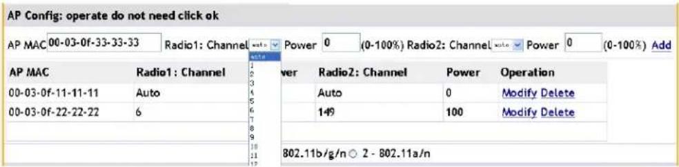
text_image
AP Config: operate do not need click ok AP MAC 00-03-0f-33-33-33 Radio1: Channel auto Power 0 (0-100%) Radio2: Channel auto Power 0 (0-100%) Add AP MAC Radio1: Channel 00-03-0f-11-11-11 Auto 00-03-0f-22-22-22 6 802.11b/g/n ○ 2 - 802.11a/n Power Radio2: Channel Power Operation Auto 0 Modify Delete 149 100 Modify Delete- Click "modify" on the right of the AP to modify it. The MAC address cannot be modified; the channel and power can be modified. Modify the channel to be 6 and modify the power to be 100. Click "submit" to complete it.
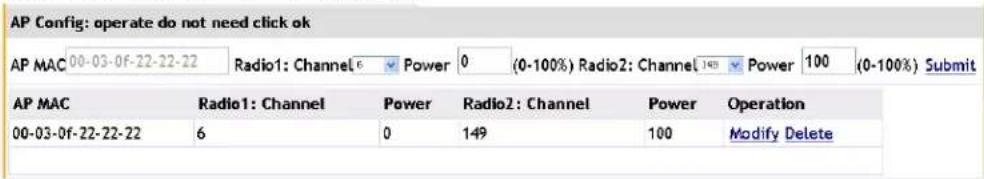
text_image
AP Config: operate do not need click ok AP MAC 00-03-0f-22-22-22 Radio1: Channel 6 Power 0 (0-100%) Radio2: Channel 149 Power 100 (0-100%) Submit AP MAC Radio1: Channel Power Radio2: Channel Power Operation 00-03-0f-22-22-22 6 0 149 100 Modify Delete- Click the "delete" button on the right of the AP to delete it.
6.1.3 Radio
The Radio configures the radio settings for the AP group. The Radio, VAP, QoS on the page is configured per Radio. Select the hardware type to dual radio and the different radio types can be selected. Switching the radio selection will cause any information not saved to be lost.
Example: Select a single box to enable the radio and select the radio mode as IEEE 802.11b/g/n, select the RF scan mode as Active, configure the radio channel bandwidth as
20MHz, and select the supported radio rates. Click "OK" to submit the configuration. The created or modified AP group will be seen.
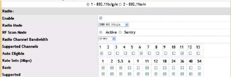
text_image
1 - 802.11b/g/n ○ 2 - 802.11a/n Radio: Enable Radio Mode IEEE 002.11w/g/n RF Scan Mode Active ○ Sentry Radio Channel Bandwidth 20 MHz Supported Channels 1 2 3 4 5 6 7 8 9 10 11 12 13 Auto Eligible ✓ ☐ ☐ ☐ ✓ ☐ ☐ ☐ ✓ ☐ ☐ Rate Sets (Mbps) 1 2 5.5 6 9 11 12 18 24 36 48 54 Basic ✓ ✓ ✓ ☐ ☐ ✓ ☐ ☐ ☐ ☐ ☐ ☐ Supported ✓ ✓ ✓ ✓ ✓ ✓ ✓ ✓ ✓ ✓ ✓- Radio mode: user can select IEEE 802.11b/g/n, IEEE 802.11b/g, 2.4GHz IEEE 802.11n, IEEE802.11b or IEEE 802.11g in radio 1; and user can select IEEE 802.11a/n, IEEE 802.11a or 5GHz IEEE 802.11n in radio 2.
- RF scan mode: includes Active and Sentry two modes.
- Radio channel bandwidth: according to the different radio modes, there are three modes of 20MHz, 40MHz and 20/40MHz can be selected.
- Auto eligible: shows the channel that can join the auto adjustment.
- Rate sets (Mbps): Select the basic and supported rates through the checkboxes.
6.1.4 VAP
The VAP or Virtual Access Point configures the network SSID's used by all the APs in a group.
Select the VAP which needs to be enabled and select the network name. Click "edit" to configure the network and more information can be viewed in chapter 5 networks.
Example: Select the second and third VAP and select the created network name, and then click "OK", the AP group will be created or modified successfully.

text_image
Vap Status Network ✓ 1 - Network1 Edit ✓ 2 - Managed SSID 2 Edit ✓ 3 - Managed SSID 3 Edit □ 4 - Managed SSID 4 □ 5 - Managed SSID 5 □ 6 - Managed SSID 6 □ 7 - Managed SSID 7 □ 8 - Managed SSID 8 □ 9 - Managed SSID 9 □ 10 - Managed SSID 10 □ 11 - Managed SSID 11 □ 12 - Managed SSID 12 □ 13 - Managed SSID 13 □ 14 - Managed SSID 14 □ 15 - Managed SSID 15 □ 16 - Managed SSID 16- VAP: It is the abbreviation of the virtual AP or AP. There are 16 VAPs under one radio, they corresponds to the network 1-16 in numerical order.
6.1.5 QoS
Configure QoS for the AC and the default values are set according to standard practices.
Example: select the template of custom and select the single box of WMM mode. Each of the EDCA parameters is configured as the default value. Click "OK" to submit the QoS configuration.
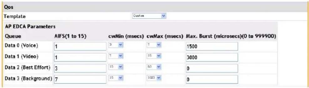
text_image
Qos Template Custom AP EDCA Parameters Queue AFS(1 to 15) cwMin (msecs) cwMax (msecs) Max. Burst (microsecs)(0 to 999900) Data 0 (Voice) 1 3 7 1500 Data 1 (Video) 1 7 15 3000 Data 2 (Best Effort) 3 15 63 0 Data 3 (Background) 7 15 1023 0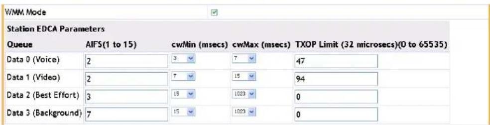
text_image
W/MM Mode Station EDCA Parameters Queue AFS(1 to 15) cw/Min (msecs) cw/Max (msecs) TXOP Limit (32 microsecs)(0 to 65535) Data 0 (Voice) 2 3 7 47 Data 1 (Video) 2 7 15 94 Data 2 (Best Effort) 3 15 1023 0 Data 3 (Background) 7 15 1023 0- Template: user can select a pre-made template, factory default or voice. Only
when the custom is selected, can the EDCA parameters be configured.
- AP EDCA parameters: user can input values or select the drop-down boxes to configure the different AP EDCA parameters.
- WMM mode: user can select the single box or not to enable or disable the WMM QoS function.
- Station EDCA parameters: user can input values or select the drop-down boxes to configure the different station EDCA parameters.
6.1.6 TSPEC
TSPEC or Traffic Specifications configures the TSPEC parameters of the AP group. This includes both characteristics and Quality of Service expectations for traffic flow.
Example: Modify the TSPEC mode to be "enable" and modify the voice ACM mode and video ACM mode to be "enable". Input the limit and timeout as the default values and click "OK" to complete the configuration.

text_image
TSPEC TSPEC Mode Enable Voice ACM Mode Enable Video ACM Mode Enable Voice ACM Limit (%) 20 (0 to 70) Video ACM Limit (%) 15 (0 to 70) Roam Reserve Limit (%) 5 (0 to 70) AP Inactivity Timeout (secs) 30 (0 to 120,0 - Disable) STA Inactivity Timeout (secs) 30 (0 to 120,0 - Disable) Legacy W/MM Queue Map Mode Disable OK Cancel6.2 Copy AP Group
A new AP group can be created or modified simply by copying.
Example:
- Click "new" button to create the AP group. Input the ID as 5 and click "copy" on the right of AP group 1. The AP group 5 will be created and its configuration will be the same as AP group 1.
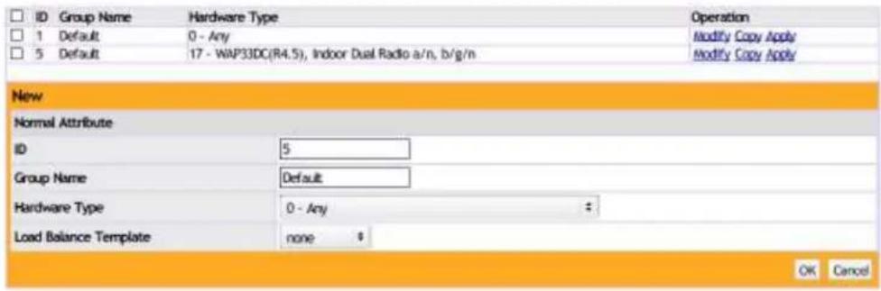
text_image
ID Group Name Hardware Type Operation 1 Default 0 - Any Modify Copy Apply 5 Default 17 - WAP33DC(R4.5), Indoor Dual Radio a/n, b/g/n Modify Copy Apply New Normal Attribute ID 5 Group Name Default Hardware Type 0 - Any # Load Balance Template none $ OK Cancel- Click "modify" on the right of AP group 5 to modify this AP group. Click "copy" on the right of AP group 1. The AP group 5 will be modified and its configuration is the same as AP group 1.

text_image
ID Group Name Hardware Type Operation 1 Default 0 - Any Modify Copy Apply 5 Default 17 - WAP33DC(R4.5), Indoor Dual Radio a/n, b/g/n Modify Copy Apply New Normal Attribute ID 5 Group Name Default Hardware Type 0 - Any # Load Balance Template none * OK Cancel6.3 Apply AP Group
Click the "apply" button on the right of the AP group to send the configuration to the APs. After configured the AP groups, the user must click "apply" to send all configuration changes to the APs.
Example: click the "apply" button on the right of AP group 5 to send the configuration to all the APs in AP group 5.

text_image
AP Groups This table lists basic information for all AP groups. Click "New" to create more AP groups or click "Modify" to change settings for existing AP groups. Click "Copy" AP group. Click "Apply" to apply the information to all APs in the AP group. ID Group Name Hardware Type Operation 1 Default 0 - Any Modify Copy Apply 2 Default 17 - WAP33DC(R4.5), Indoor Dual Radio a/n, b/g/n Modify Copy Apply 5 Default 17 - WAP33DC(R4.5), Indoor Dual Radio a/n, b/g/n Modify Copy Apply New DeleteChapter 7 Security Authentication
Security authentication module includes radius configuration and LDAP configuration. The radius configuration includes global configuration, radius authentication server configuration, radius accounting server configuration, radius group manage and radius configuration.
7.1 Radius Configuration
7.1.1 Global Configuration
Before using the radius authentication and accounting service, configure an accounting server and an authentication server first. The server configuration is viewed in the next section. After configured the accounting and authentication servers, select the radius authentication status box to enable the radius function; it corresponds to the command of "aaa enable". Select the radius accounting status box to enable the radius accounting function; it corresponds to the command of "aaa-accounting enable". Configure the key in the radius key box and it corresponds to the command of "radius-server key". The key must be the same as the one of the radius server for authentication. Configure the address which is used alternately between AC and radius in the radius NAS IPV4 and radius source IPV4 boxes. The configuration of NAS IP corresponds to the command of "radius nas-ipv4" and the radius source IPV4 corresponds to the command of "radius source-ipv4".
Example: Enable the radius authentication and accounting server and configure the radius key as test. The NAS IPV4 and source IPV4 are both 10.0.0.250:
Radius Configuration
| Global Configuration | |
| Radius Authentication Status | |
| Radius Accounting Status | |
| Radius Key | test |
| Radius NAS IPV4 | 10.0.0.250 |
| Radius Source IPV4 | 10.0.0.250 |
After configured, click "submit" to same the configuration.
7.1.2 Radius Authentication Server
Configuration
The radius authentication configuration corresponds to the command of "radius-server authentication host" and it can configure the address of the authentication server.
Example: Configure the server IP address as 10.0.0.15. The server port can be left blank, and it will use the default value. Select the primary authentication server as below:

text_image
Radius Authentication Server Configuration Radius Authentication Server Configuration Authentication Server Port(optional) Primary Authentication Server Server IP Address 10.0.0.15 Authentication Server Port (optional) Primary Authentication Server Add DeleteClick "add" to complete it as below:
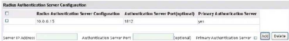
text_image
Radius Authentication Server Configuration Radius Authentication Server Configuration Authentication Server Port(optional) Primary Authentication Server 10.0.0.15 1812 yes Server IP Address Authentication Server Port (optional) Primary Authentication Server Add DeleteThe default authentication server port is 1812. If removing a server, select it first and then click "delete". Before deleted the last authentication server, the radius authentication server must be disabled first. Click "submit" to save the configuration.
7.1.3 Radius Accounting Server Configuration
The radius accounting configuration corresponds to the command of "radius-server accounting host" and it can configure the address of the accounting server.
Example: Configure the accounting server IP as 1.2.3.4. The server port can be left blank, and it will use the default value. Select the primary accounting server as below:

text_image
Radius Accounting Server Configuration Radius Accounting Server SenConfiguration Accounting Server Port(optional) Primary Accounting Server Accounting Server IP 1.2.3.4 Accounting Server Port (optional) Primary Accounting Server Add DeleteClick "add" to complete it as below:
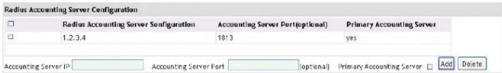
text_image
Radius Accounting Server Configuration Radius Accounting Server Senfuguration Accounting Server Port(optional) Primary Accounting Server 1,2,3,4 1813 yes Accounting Server IP Accounting Server Port (optional) Primary Accounting Server Add DeleteThe default accounting server port is 1813. If removing the accounting server, select it first and then click "delete". Before deleted the last accounting server, the radius accounting server must be disabled first. Click "submit" to save the configuration.
7.1.4 Radius Group Manage
The radius group manage corresponds to the command of "aaa group server radius".
It can configure multiple radius groups.
Example: Configure two radius groups of wlan1 and wlan2. Input the group name in the radius group name box and click "add" to complete it as below:
Radius Group Manage
| ☐ | Radius Group Name |
| ☐ | wlan1 |
| ☐ | wlan2 |
7.1.5 Radius Configuration
Radius configuration will bind the radius server address to the radius group. Multiple radius addresses can be bound to each group name but each radius address only can be bound to one radius group.
Example: Bind the 10.0.0.15 server to wlan1 and bind 1.2.3.4 server to wlan2. Choose the configured radius group in the radius group names and choose the server address in the radius server IP drop-down box. Click "add" to complete it.
Radius Configuration
| ☐ | Radius Group Name | Radius Server IP |
| ☐ | wlan1 | 10.0.0.15 |
| ☐ | wlan2 | 1.2.3.4 |
After configured, click "submit" to save the configuration.
7.2 LDAP Configuration
LDAP configuration corresponds to the command of "ldap server + subsequent configuration" and it is mainly used as the portal authentication server and user management server. The main configuration items include server IP address, server port, basic DN, user attribute, user object type, authentication mode and filter condition. The server IP address is the LDAP server IP address, the server port is the LDAP server port and the default port is 389. The basic DN is the base DN that a user wants to find on the LDAP server. The user attribute is the user attribute on a LDAP server. The user object type is the type of the LDAP server. The authentication mode includes simple and anonymous authentication; the simple authentication needs the user name and password. The filter condition is the additional condition for configuring user authentication.
Example: Configure the LDAP server 1 and its address is 192.168.1.10, the port is 389, DN is abcd, the user attribute is cn, the user object type is abc, the authentication mode is the simple authentication, the user name is wlan, the password is 123456, and the filter condition is inetUserStatus=Active.
LDAP Configuration
☐ ID Server IP Address Server Port Basic DN User Attribute User Object Type Authentication Mode Filter Condition Operation
How

text_image
ID 1 (1-8) Server IP Address 192.168.1.10 Server Port 389 (1-65535) Basic DN abcd User Attribute cn User Object Type abc Authentication Mode User Name wlan (1-64) Password 123456 (1-32) Filter Condition InetUserStatus=Active OK CancelClick "OK" to confirm it, the configuration will be saved as below:
LDAP Configuration
ID Server IP Address Server Port Basic DN User Attribute User Object Type Authentication Mode Filter Condition Operation 1 192.168.1.10 389 dc=dcn cn abc Authentication inatUserStatus=Active Modify
After configured, select the "modify" on the right to modify the configured LDAP server. To delete the configured LDAP server select the "delete" button.
Chapter 8 Discovery
8.1 L3/IP Discovery
8.1.1 Enable/Disable L3/IP Discovery
Click the WLAN configuration→Discovery→L3/IP discovery, and then click "enable" and select the "submit" button. To disable the feature, uncheck the enable box.

text_image
L3/IP Discovery Enable ✓ IP Address Submit8.1.2 Add IP of L3/IP Discovery
Add in the IP address in the IP address box and click "add" to include it in the discovery list.

text_image
IP Address 10.0.0.1 Add Delete8.1.3 Delete IP Address from L3/IP Discovery List
Select the IP address which needs to be deleted, and click the "delete" button and confirm it. The IP address will then be deleted.
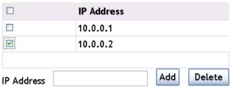
text_image
IP Address 10.0.0.1 10.0.0.2 IP Address Add Delete8.2 L2/VLAN Discovery
8.2.1 Enable L2/VLAN Discovery
Click the WLAN configuration→Discovery→L2/VLAN discovery, and then click "enable" and select the "submit" button.
L2/VLAN Discovery
Enable
Submit
8.2.2 Add VLAN of L2/VLAN Discovery
Add the VLAN id in the VLAN box and click "add" to include it in the discovery list.

text_image
VLAN VLAN 10 Add Delete8.2.3 Delete VLAN from L2/VLAN Discovery List
Select the VLAN which needs to be deleted, and click the "delete" button and confirm it. The VLAN will then be deleted.

text_image
VLAN 10 - 20 - VLAN0020 34 - VLAN Add DeleteChapter 9 Provisioning
Click "WLAN configuration->provisioning" to enter into the provisioning page.
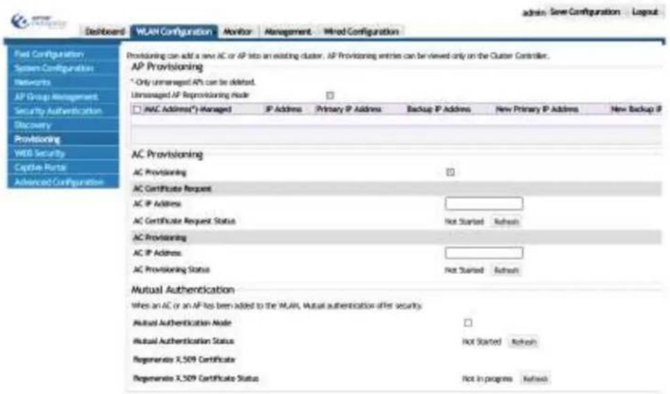
text_image
admin: Save Configuration Dashboard WLAN Configuration Monitor Management Hind Configuration Field Configuration System Configuration Networks AP Group Management Security Authentication Discovery Provisioning WEB Security Capture Hours Advanced Configuration Providing can add a new AC or AP into an existing cluster. AP Provisioning entries can be viewed only on the Cluster Controller. AP Provisioning * Only Unmanaged APs can be deleted. Unmanaged AP Reprovisioning mode □ IAC Address(*)-Managed IP Address Primary IP Address Backup IP Address New Primary IP Address New Backup IP AC Provisioning AC Provisioning □ AC Certificate Request AC IP Address: AC Certificate Request Status Not Started Refresh AC Provisioning AC IP Address: AC Provisioning Status Not Started Refresh Mutual Authentication When an AC or an AP has been added to the WLAN, Mutual authentication offers security. Mutual Authentication Node □ Mutual Authentication Status Not Started Refresh Regenerate X,509 Certificate Regenerate X,509 Certificate Status Not In programs Refresh9.1 AP Provisioning
AP provisioning specifies the AP provisioning options which can be controlled from the AC. It can provision an AP which was added into the cluster and it can also provision an AP which is not added in the cluster (AP provisioning). Appoint an AC for an AP on the Controller, the certificate that they need to authenticate will be transmitted in the cluster automatically.
Example: Click "modify" button of the AP which needs provisioning and choose the new primary IP address and new backup IP address; and then click "submit" to complete it. Choose the AP which needs provisioning and click "deploy".
Notice: the AP with successful provisioning can be associated with the AC after restarting.
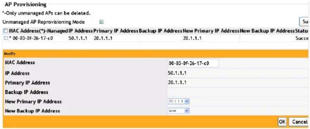
text_image
AP Provisioning *-Only unmanaged APs can be deleted. Unmanaged AP Reprovisioning Mode MAC Address(*)-Managed IP Address Primary IP Address Backup IP Address New Primary IP Address New Backup IP Address Status * 00-03-0f-26-17-c0 50.1.1.1 20.1.1.1 20.1.1.1 Suce Modify MAC Address 00-03-0f-26-17-c0 IP Address 50.1.1.1 Primary IP Address 20.1.1.1 Backup IP Address New Primary IP Address 20.1.1.1 New Backup IP Address NONE OK Cancel9.2 Switch Provisioning
Switch provisioning adds the AC controller into the cluster. This AC needs to get the certificate of all other ACs in the cluster; and every AC in the cluster also needs to get the certificate of all corresponding AC's.
Example:
- Choose the switch provisioning and click "submit" to enable this function.
Switch Provisioning
Switch Provisioning

Submit
- Input 20.2.2.2 (the IP address of the AC which needs to be added in to the cluster) in the switch IP address box of the switch certificate request and click "start". The certificate request will start. Click "refresh" to view the status.
Switch Certificate Request
Switch IP Address
20.2.2.2
Switch Certificate Request Status
Requested
Refresh
Start
- Input 20.2.2.2 (the IP address of the AC which needs to be added in to the cluster) in the switch IP address box of the switch provisioning and click "start". The provisioning will start. Click "refresh" to view the status.
Switch Provisioning
Switch IP Address
20.2.2.2
Switch Provisioning Status
Requested
Refresh
Start
9.3 Mutual Authentication
The mutual authentication can be enabled to avoid an unknown device joining the cluster. This function will only allow a device with a valid certificate to authenticate and join
the cluster by issuing the X.509 certificate.
Example:
- Choose "network mutual authentication mode" on-off and click "submit" to enable this mode. Click the "refresh" button to view the status of the last network mutual authentication.
Mutual Authentication
When AC or AP has added to the wlan, Mutual authentication offer sucerity.
Network Mutual
Authentication Mode
Network Mutual Authentication Status
√
In progress Refresh
Submit
- Click "start" button of regenerate X.509 certificate to start regenerating the certificate. Click "refresh" button to view the process of the AC authentication regeneration.
Notice: The certificate is only produced one time; the status will turn back to the "not started" status after it has been created.
Regenerate X.509
Certificate
Regenerate X.509 Certificate Status
Start
Start Refresh
Chapter 10 WIDS Security
Click WLAN Security->WIDS security to enter into the WIDS security configuration page which including 3 sections: AP configuration, client Configuration and a black/white list. Every module occupies one separate section and they can be used to configure the WIDS AP configuration, WIDS client configuration and black/white list.
text_image
WIDS AP Configuration Rogue AP detection configuration Administrator configured rogue AP Enable Managed SSD from an unknown AP Managed SSD from a fake managed AP Enable AP without an SSD Fake managed AP on an invalid channel Enable Managed SSD detected with incorrect security Invalid SSD from a managed AP Enable AP is operating on an illegal channel Standalone AP with unexpected configuration Enable Unexpected WIDS device detected on network Unmanaged AP detected on wired network Enable Administrator configured rogue SSD Wired Network Detection Interval (1-3600 seconds, 0Disable) NO Rogue Detected Trap Interval If there are rogue APs in the network, the AC sends a trap periodically. Rogue Detected Trap Interval NO-3600 seconds, 0Disable) No10.1 AP Configuration
Click AP configuration->WIDS AP configuration to choose enable or disable to the available options listed below.
AP Configuration
WIDS AP Configuration
Administrator configured rogue AP
Managed SSID from a feku managed AP
Fake managed AP on an invalid channel
Invalid SSID from a managed AP
Standalone AP with unexpected configuration
AP De-Authentication Attack Lifetime(seconds)
Rogue Detected Trap Interval (seconds)
Wired Network Detection Interval (seconds)
Enable
20014
Nina
36.12
(1) 2017年1月1日
□2021.5
600 (60 to 3600)
300 (60 m 2600.0 - 0disable)
60 (1 to 3600.0 - [disable]
Managed SSID from an unknown AP
AP without an SSID
Managed SSID detected with incorrect security
AP is operating on an illegal channel
Unexpected WDS device detected on network
AP De-Authentication Attack
OUI Database Mode
Unmanaged AP detected on wired network
Hensible
Bizable
Jurable
Disable
Hicable
Jinable
123
Jusable

- Administrator configured rogue AP—enables the rogue AP detection configured by the administrator.
- Managed SSID from a fake managed AP—enables/disables the illegal Vendor filed detection in Beacon frame.
- Fake managed AP on an invalid channel—enables/disables the detection that the Beacon frame of the managed AP is received from the invalid channel.
- Invalid SSID from a managed AP—enables/disables the detection of managed AP sending the invalid SSID.
- Standalone AP with unexpected configuration—enables/disables the detection of standalone AP with unexpected configuration.
- AP de-authentication attack lifetime (seconds)—configures the AP de-authentication attack lifetime and the default value is 600 seconds.
-
Rogue detected trap interval (seconds)—the default value is 300s.
-
Wired network detection interval (seconds)—configures the shortest waiting interval of every detection and the default value is 60s.
- Managed SSID from an unknown AP—enables/disables the detection of the illegal AP imitating the lawful SSID.
- AP without an SSID—enables/disables the detection that no SSID field in Beacon frame.
- Managed SSDI detected with incorrect security—enables/disables the detection that AP uses the incorrect security authentication mode.
- AP is operating on an illegal channel—enables/disables the detection that the Beacon frame of managed AP is received on the illegal channel.
- Unexpected WDS device detected on network—enables/disables the detection of an AP that is working in the WDS mode.
- AP de-authentication attack—enables/disables the rogue AP mitigation function.
- OUI database mode—configures the OUI database mode used in OUI legality detection.
- Unmanaged AP detected on wired network—enables/disables the detection of the unmanaged AP accessing the wired network.
10.2 Client Configuration
Select the client configuration->WIDS client configuration page to configure this section as listed below.
text_image
Client Configuration WCS Client Configuration Net Present in 300 Database Text Configured Authentication Rate Text Configured the Authentication Requests Rate Text Configured the Association Rate Text Authentication with Unknown AP Text Known Client Database Lookup Method Regue Detected Trap Interval(seconds) Be Authentication Requests Threshold Value Authentication Requests threshold Value Probe Requests Threshold Value Association Requests threshold Value Be Association Requests Threshold Value Dynamic Blackout mode Net Present in Known Client Database Text Configured Probe Requests Rate Text Configured Association Rate Text Medium Authentication failures Test Client Threat Mitigation Known Client Database Radiant Server Name De-Authentication Requests: Threshold interval (seconds) Authentication Requests: Threshold interval (seconds) Probe Requests: threshold interval (seconds) Association Requests: Threshold interval (seconds) Misassociation Requests: threshold interval (seconds) Authentication Failure: Threshold Value Dynamic Blackout Life Time(seconds) Default REACH: 241.00 90 (1 to 260.0) 60 (1 to 260.0) 50 (1 to 260.0) 50 (1 to 260.0) 50 (1 to 260.0) 50 (1 to 260.0) 50 (1 to 260.0) 50 (1 to 260.0) 50 (1 to 260.0) 50 (1 to 267.77) 50 (1 to 267.77) 50 (1 to 267.77) 50 (1 to 267.77) 50 (1 to 267.77) 50 (1 to 267.77) 50 (1 to 267.77) 50 (1 to 267.77) INDIVI- Not present in OUI database test—enables/disables the OUI legality detection.
- Configured authentication rate test—enables/disables the authentication requests frame flood attacks detection.
- Configured de-authentication requests rate test—enables/disables the de-authentication requests frame flood attacks detection.
- Configured disassociation rate test—enables/disables the disassociation requests frame flood attacks detection.
- Authentication with unknown AP test—enables/disables the detection of lawful client associating with an unknown AP.
- Known client database lookup method—configures the method of the known client database lookup and it includes two methods of local and radius.
-
Dynamic blacklist mode—enables/disables the dynamic blacklist function.
-
Not present in known client database test—enables/disables the detection of the Known Client Database judging illegal.
- Configured probe requests rate test—enables/disables the probe requests frame flood attacks detection.
- Configured association rate test—enables/disables the association requests frame flood attacks detection.
- Maximum authentication failures test—enables/disables detection of the maximum failed authentication.
- Client threat mitigation—enables/disables the Known Client protection function.
10.3 Known Client
Select the known client configuration page to configure the MAC authentication mode and add, delete or modify the black and white list.
Known Client
MAC Authentication Mode
White-list
Submit

MAC
Description
Authentication Action
Operation

00-0d-0a-30-9a-6a
Global Action
Modify
MAC
Description
Authentication Action

Global Action Add Delete
10.3.1 MAC Authentication Mode
Select the known client->MAC authentication mode to choose the white or black list as the MAC authentication mode of known client.
MAC Authentication Mode
Blacklist
Submit
Configure the MAC authentication mode as black-list and click "submit" to complete it.
MAC Authentication Mode
White-list
Submit
Configure the MAC authentication mode as white-list and click "submit" to complete it.
10.3.2 Black/white List Configuration
Select the black/white list configuration page to input the client MAC, description, authentication action and click "add" to complete the configuration.
MAC
Description
Authentication Action

- MAC—client mac
■ Description—the client description information - Authentication action—includes global action, grant and deny. When the authentication action is configured as grant or deny, the client will be granted or denied no matter the authentication mode. Only when the action is configured as global action, the MAC authentication mode will be effective, it will be denied in the black-list, but will be granted in the white-list.
Example:
- Input the client MAC as 00-00-00-00-00-01 and input the description as abcd. Choose the authentication action as grant and click the "add" button to complete the configuration;
- Select the added black or white list and click "delete" button to complete the client deletion. Select the single box of MAC and click "delete" to delete all the clients information of the current page;
- Click "modify" of 00-00-00-00-00-01 to modify the client description, authentication action. Click "submit" to apply it. The MAC address itself cannot be modified.

text_image
Known Client MAC Authentication Mode Date-List Submit MAC Description Authentication Action Operation 00-00-00-00-01 abcd Global Action Modify MAC 00-00-00-00-01 Description abcd Authentication Action Grant Submit DeleteChapter 11 Captive Portal
Click WLAN configuration -> Captive Portal to enable the Captive Portal configuration page.

text_image
Front Configuration System Configuration Networks AF Group Management Security Authentication Discovery Provisioning WIDS Security Captive Portal Advanced Configuration Dashboard WLAN Configuration Monitor Management Wired Configuration Captive Portal Global Configuration Enable: Operational Status Disabled Disable Reason Administrator Disabled Authentication Type External Portes: Internal Portes Peer Switch Statistics Repeating Interval (sec) 120 (15-3600, 0+Disple) Portal Server Configuration Server Name IP Address Port Server Key Operation Server Name: IP Address: Port: 7749 (3-85525) Server Key: Add Remove Free Resource Configuration Free Resource ID Source IP/Mask Length Destination IP/Mask Length Operation Free Resource ID (1-32) Source IP/Mask Length Example 192.168.1.1/24 Destination IP/Mask Length Example 192.168.1.1/24 And Delete11.1 Global Configuration
Select the single box to enable the captive portal function in global mode; cancel it to disable this function. This function includes the captive portal function on AC and AP.
| Enable Captive Portal | |
| CP Global Operational Status | Enabled |
11.2 Captive Portal Authentication Type
Captive Portal authentication type includes external portal and internal portal. Click "internal" or "external" to choose the captive portal authentication type as below:
Captive Portal Authentication Type External Internal
11.3 Portal Server Configuration
Portal server configuration can add or delete the portal server name, IP address, port and the server key.
- Server name—the name of the appointed portal server
- IP address—the IP address of the Portal server
- Port—the port which is monitored when the Portal Server receives the packet. It needs to be configured according to the actual monitored port. The monitored port of DCSM is 50100 and it is 2000 for the CITY-HOT portal server monitored port.
- Server key—configures the portal server authentication key.
Example:
- Configure the portal server name as wlan_portal, input the IP address as 192.168.10.2, and the port is 8080, the server key is test. Click "add" to complete the configuration.
- Select the portal server which needs to be deleted and click "delete".
text_image
Server Name IP Address Port Server Key wlan-portal 192.168.10.2 8080 (0-65535) test Add Delete- Click "modify" on the right of the portal server of wlan_portal to modify the IP address, port and server key. The server name cannot be modified.

text_image
Server Name IP Address Port Server KeyOperation wlan-portal 192.168.10.2 8080 Nepal test Modify Server Name wlan-portal IP Address 192.168.10.2 Port 8080 (0-65535) Server Key Nepal test Save Delete11.4 Free Resource Configuration
Free-resource function is used to control the access of the resource in the captive portal module. By configuring this rule, it allows a specific client to access a specific network resource directly without the portal authentication.
- Free Resource ID--Free Resource rule number, the range is from 1 to 32.
- Source IP/Mask length—the source IP address field in the rule and the length of its mask
- Destination IP/Mask length-- the destination IP address field in the rule and the length of its mask
Example:
- Input the Free Resource ID as 1, fill in the source IP/Mask length as 192.168.1.100/24 and fill in the destination IP/Mask length as 10.1.1.0/32. Click "add" to complete the configuration.
- Select the Free Resource rule which needs to be deleted and click "delete".
text_image
Free Resource ID 1 (1 - 32) Source IP/Mask Length 192.168.1.100/24 Destination IP/Mask Length 10.1.1.1/32 Add Delete- Click "modify" on the right of the Free Resource ID to modify the source IP/Mask length and the destination IP/Mask length. The Free Resource ID cannot be modified.

text_image
Free Resource ID Source IP/Mask Length Destination IP/Mask Length Operation 1 192.168.1.100/24 10.1.1.1/32 Modify Free Resource ID 1 (1 - 32) Source IP/Mask Length 192.168.1.100/24 Destination IP/Mask Length 10.1.1.1/32 Save Delete11.5 MAC Portal Configuration
The MAC Portal function is used for specific users on the network. The administrator can configure these users to allow them to connect using only a MAC address. This process allows the user to skip the authentication portal.
Click Captive Portal->MAC Portal configuration to add or delete the MAC address of the MAC Portal user.
Example:
- Input the MAC Portal user MAC as 20-7c-8f-7c-8f-64 and click "add" to complete it.
- Select the MAC portal user MAC which needs to be deleted and click "delete" to complete it.
MAC Portal User Mac
20-7c-8f-7c-8f-64 Add Delete

text_image
MAC Portal User Mac 00-00-00-00-00-01 MAC Portal User Mac 00-00-00-00-00-04 Add Delete11.6 Portal Instance Configuration
- Instance ID—configures the Captive Portal ID, the range is from 1 to 10 and the system supports 10 CP configurations max.
- instance name—appoint a CP name
- Enable—To enable the CP page
- Enable Mac-Portal—To enable the Mac compatible CP
- Protocol mode—the protocol mode that the CP supports, it includes HTTP and HTTPS.
- Authentication method—it includes two methods of the authentication based on MAC and the authentication based on MAC and IP.
- Additional HTTP port—configures the additional http port, it does not include 80 and 443. 0 is the default value and it means that there is no additional HTTP port and it adopts the default 80 port.
- Auth mode—configures the authentication mode that the CP supports and it includes RADIUS, LDAP and NONE.
- Radius auth server—appoints the radius authentication server which will be used.
- Radius accounting server-- appoints the radius accounting server which will be
used.
- Radius accounting update interval (secs)—configures the updating interval of the radius accounting.
- IPv4 Portal server—appoints the IPv4 portal server which will be used.
- IPv6 Portal server-- appoints the IPv6 portal server which will be used. The IPv6 portal server cannot be configured on web currently.
■ Free Resource—binds the free-resource rule for the CP.
- Idle timeout (secs)—the idle timeout of CP. 0 is the default value and it means that there is no time limitation.
- Session timeout (secs)—the session timeout of CP. 86400 is the default value and 0 means that there is no session limitation.
- Max up bandwidth (bytes/sec)—configures the max up bandwidth of the user. The default value is 0 and it means that there is no bandwidth limitation.
- Max down bandwidth (bytes/sec)—configures the max down bandwidth of the user. The default value is 0 and it means that there is no bandwidth limitation.
- Max transmit bytes—configures the max bytes that the user allows sending. The default value is 0 and it means that there is no byte limitation.
- Max receive bytes—configures the max bytes that the user allows receiving. The default value is 0 and it means that there is no byte limitation.
- Max total bytes—configures the max bytes that the user allows sending and receiving. The default value is 0 and it means that there is no byte limitation.
- Listen packet port—configures the port which is listened when portal server receives the packet.
Example:
-
Click "add" button and input the CP ID, CP name. Enable the captive portal configuration and choose the authentication mode, etc. Click "OK" to complete the creation.
-
Click the "modify" of wlan_CP to modify its configuration.
-
Choose the added CP and click "delete" button to delete it.
| New | ||
| Instance ID | ||
| Instance Name | Default | |
| Enable | 0 | |
| Enable Mac-Portal | 0 | |
| Protocol Mode | HTTP HTTP HTTPS | |
| Authentication Method | Max Based Max Up Based | |
| Additional HTTP Port | 0 (8-65525) | |
| Auth Mode | RADIUS LDSP NONE | |
| Radius Auth Server Group Name | ||
| Radius Accounting Enable | 0 | |
| Radius Accounting Server Group Name | ||
| Radius Accounting Update Interval (secs) | 300 (90-3600) | |
| IPv4 Portal Server Name | home + | |
| IPv6 Portal Server Name | home + | |
| Free Resource | ||
| Idle Timeout (secs) | 0 (8-900) | |
| Session Timeout (secs) | 06400 (8-96400) | |
| Max Up Bandwidth (Bytes/sec) | 0 (8-13687891), 0 Undirected | |
| Max Down Bandwidth (Bytes/sec) | 0 (8-13687891), 0 Undirected | |
| Max Transmit Bytes | 0 (8-4294967295, 0 Undirected) | |
| Max Receive Bytes | 0 (8-4294967295, 0 Undirected) | |
| Max Total Bytes | 0 (8-4294967295, 0 Undirected) | |
| Listen Packet Port | 2000 (1-65525) | |
| ID | CP Name | CP Mode | Protocol Mode | Verification | Operation |
| 1 | wlan_CP | Enable | HTTPS | RADIUS | Modify |
Chapter 12 Config Push
Click "WLAN configuration->advanced config->config push" to enter into the config push page which includes two modules: config push and config push option. The other AC's in the cluster will be listed here. You can select which AC to push the configuration to, and set the different options for each.
12.1 Config Push
The module of config push shows the IP address of an AC in the cluster. One AC can be chosen to run the "config push"; or all the ACs in the current cluster can run the "all push".

text_image
Config Push IpAddr 22.2.2.2 11.1.1.1 Config Push All PushThe IP addr in the figure means the peer switch; the configuration can be pushed to these two switches.
If there is no other switch in the cluster, the "IP addr" bar is empty. This function will only work with more than 1 AC.

text_image
Config Push IpAddr Config Push All Push12.2 Config Push Option
Used to configure the configuration transferred by the config push option. Every option is hidden by default. Click "config push option" to open it and click "hide push option" to auto hide the options.
Config Push Option
After selecting the "config push option", click each option button and select "enable" or "disable".
Config Push Option
| Global | Enable | √ |
| Discovery | Enable | √ |
| Channel/Power | Enable | √ |
| AP Database | Enable | √ |
| AP Profile | Enable | √ |
| Known Client | Enable | √ |
| Captive Protal | Enable | √ |
| Radius Client | Enable | √ |
| QoS Acl | Enable | √ |
| QoS Diffserv | Enable | √ |
| WDS Group | Enable | √ |
| Device Location | Enable | √ |
Submit
Click "submit" and the configuration will be saved.
Chapter 13 AP Image Upgrading
13.1 AP Image Auto Upgrade
The automatic upgrading can load the AP firmware version to the flash of the AC. When another AP is connected and discovers the new firmware version, it will download the new file.
Configure the AP image auto upgrade:
- Choose AP auto upgrade mode and click "submit" to start the AP image auto upgrade:
AP Image Auto Upgrade
AP Auto Upgrade Mode

Submit
- Choose AP image type as below:
AP Image Type

When view the table for hardware type supported by Image type, click the following content to view it:
The Table for AP Hardware Type Supported by Image Type
3 Add the AP Image URL.
Add the AP image URL in the box as below:
AP Image URL(flash:/file name)
flash:/upgrade_2_0_3
Add
Delete
Click "add" as below:
| AP Image Type | AP Image URL | Operation | |
| 1 | flash:/upgrade_2_0_3_39.tar | Modify |
Click "modify" to modify the AP image URL; to remove it, click on the delete button.
- Click "integrated AP image availability table" list to view the configured AP image.
13.2 AP Manual Upgrade Configuration
The AP manual upgrade configuration means the process of updating the firmware is done by the user. The ability to select and upgrade a specific AP is available here.
- Add the AP Image URL to start the configuration as below:
AP Manual Upgrade Configuration

text_image
AP Image Type AP Image URL Operation Add DeleteClick the "add" and the options will be listed below:
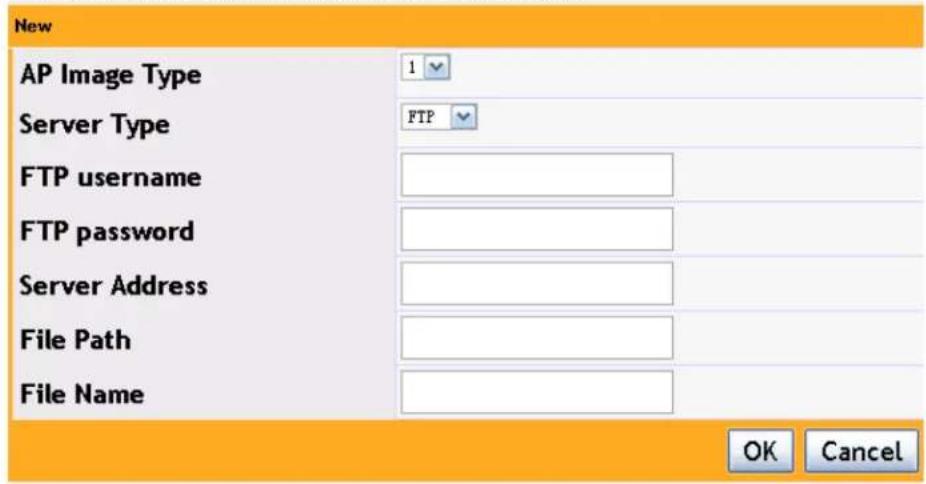
text_image
New AP Image Type 1 Server Type FTP FTP username FTP password Server Address File Path File Name OK CancelClick "AP Image Type" box to choose the image type; user can choose FTP or TFTP for the "server type". The configuration of choosing FTP server is shown below:

text_image
New AP Image Type Server Type FTP username FTP password Server Address File Path File Name 1 FTP admin 111111 10.0.0.115 R4_R5_2_0_3_39.tar OK CancelThe FTP username and password should be correct; the file name and the server address should also be verified. Enter the file location into the file path and include the filename with .tar.
| AP Image Type AP Image URL | Operation | |
| 1 | ftp://admin:111111@10.0.0.115//79XX_R4_R5_2_0_3_39.tar | Modify |
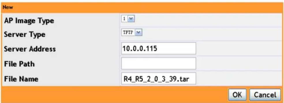
The configuration of choosing TFTP server is shown below:
text_image
New AP Image Type Server Type TFTP Server Address 10.0.0.115 File Path R4_R5_2_0_3_39.tar File Name OK CancelConfigure the server address and file name. If the file is in the server root directory, it cannot be written. If it is not in the root directory, the file name should be entered and click "OK" to complete this configuration.
AP Manual Upgrade Configuration
| □ AP Image Type | AP Image URL | Operation |
| □ 1 | tftp://10.0.0.115//R4_R5_2_0_3_39.tar | Modify |
If user wants to delete or modify a configured AP image URL, select it and then click "delete" or "modify" to modify it.
- After configured the AP Image URL, configure the group size and image download type as below:
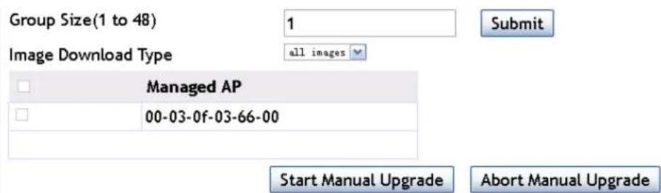
text_image
Group Size(1 to 48) 1 Submit Image Download Type all images Managed AP 00-03-0f-03-66-00 Start Manual Upgrade Abort Manual Upgrade- Group: it means the number of AP in each upgrading
- Image downloaded type: upgrade the AP with the specific img type each time. The img type includes none, 1\~5 and all images.
The "none" means to upgrade only one AP; the "all images" means to upgrade all the types of image; other options means to upgrade the specific type of image.
-
Click "start manual upgrade" button to start the AP upgrading; click "abort manual upgrade" to stop it.
-
After upgrading, show the AP upgrading status as below:
| Global Status | Code Transfer In Progress | ||
| Download Count | 1 | ||
| Success Count | 0 | ||
| Failure Count | 0 | ||
| Abort Count | 0 | ||
| Managed AP | Location | Status | Software Version |
| 00-03-0f-03-66-00 | Code Transfer In Progress | 2.0.3.42 | |
After upgrading, it will show the successes upgrading as below:

Chapter 14 Load Balance
Click "WLAN configuration->advanced config->load balance" to open up the load balance configuration page.
14.1 Create Template
The load balance template 1 exists and it is disabled by default. It cannot be removed, it can only be modified.
There is the "new" button on the bottom left corner on the page. Click it to configure the new load balance template. The new ID cannot be the same as the existing ID:

text_image
New ID 2 (1-16) Load-balance Mode Disable Session Traffic Session Window 15 (1-256) Session Threshold 4 (1-8) Traffic Window(Mbps) 60 (1-100) Traffic Threshold(Mbps) 20 (1-100) Load-balance Denial Threshold 3 OK CancelThe load balance includes "session" and "traffic". These two modes correspond to the two parameters in this section.
The session mode allows the AC to limit users based on the number of users currently connected. Traffic mode allows the AC to limit user connections based on the current bandwidth usage.
"load-balance denial threshold" means the number of times the AP can refuse a client before receiving its association request.
The AC will decide to allow the client association according to the number of the clients in the current WLAN system, it will also monitor the load on the radio interface of the local AP. When the load exceeds the maximum value, it will send a trap to the network management device. The AC can control the number of clients according to the total number when they connect, it can also release the clients when it discovers these clients exceed the maximum value.
14.2 AP Profile Associated Load Balance Template
After creating the load balance template, it needs to be added to the AP profile, and
issue the configuration to the AP.
Click "WLAN configuration->AP Group Management" to find the group ID (AP profile) which needs to be bound to the load balance template, and click the "modify" button.

text_image
AP Groups This table lists basic information for all AP groups. Click 'New' to create more AP groups or click 'Modify' to change settings for existing AP groups. Click 'Copy' AP group. Click 'Apply' to apply the information to all APs in the AP group. ID: Group Name Hardware Type Operation 1 Default D - Any Modify Copy Apply 2 Default 17 - MAP33DC/R4 SL, Indoor Dual Radio a/v, b/g/n Modify Copy Apply 3 Default 17 - MAP33DC/R4 SL, Indoor Dual Radio a/v, b/g/n Modify Copy Apply Previewing WBS Security Captive Portal Advanced Configuration NewFind the "load balance template" in the modification page and choose the template ID created before from the drop-down list; save the modification.
After modified, click "apply" on the right of that group ID to issue the parameters to one or more APs which use this group ID.
14.3 Delete Load Balance Template
Choose one or more templates from the list in the load balance page and click "delete" button.
A template which is in use by an AP group cannot be deleted. Please release the association with AP in the "AP management" page first; and then delete it.
Template 1 cannot be deleted.
Chapter 15 Time Limit Policy
The time limit policy is used to configure the user on-line time including network time limit configuration and radio time limit configuration. The network time limit configuration is based on the network and it limits clients access to the network by disabling VAP. The radio time limit configuration is under the radio and it limits clients to access the network by disabling the radio. These two policies both include the cyclical policy and UTC policy. The cyclical policy is used to configure the time of one day or the week, for example, stop the network access from xx : xx to xx : xx. The UTC policy is used to configure the detailed date, for example, allow or stop the network access from xx : xx on xx xx, xxxx to xx : xx on xx xx, xxxx.
15.1 Network TimeLimit Configuration
Click the network ID and choose to configure the timelimit policy under the network which needs to be accessed, configure the start and end time of the cyclical policy. In the "weekday", user can choose "every day" or the detailed weekday. After configured, the network cannot be accessed every day or on that weekday. In the UTC policy, the start and end time should be configured as the detailed time. The network status includes "up" and "down", it means to enable or disable the VAP that the network corresponds to in this time.
Example:
Configure the network 1 to limit the network access from 8:00-18:00 every day.

text_image
Network TimeLimit Configuration Network ID 1 - nd Start Time End Time Weekday Network Status Cyclical Policy: Start Time 8:00 End Time 18:00 Weekday EveryDay AddClick "add" to complete it.
| □ | Start Time | End Time | Weekday | Network Status |
| □ | 08:00 | 18:00 | EveryDay | Down |
Example:
Configure the network2 to access the network from 9:00 on May 13, 2013 to 18:00 on May 18, 2013.

text_image
UTC Policy: Start Time 2013-5-13 9:00 End Time 2013-5-18 18:00 Network Status Add DeleteClick "add" to complete it.
text_image
Network ID Start Time End Time Weekday Network Status 2013-05-13 09:00 2013-05-18 18:00 Up Cyclical Policy: Start Time hh:mm End Time hh:mm Weekday Everyday Add UTC Policy: Start Time YYYY-MM-DD hh:mm End Time YYYY-MM-DD hh:mm Network Status Tave Add DeleteChoose the configured policy and click "delete" button to delete the policy.
15.2 Radio TimeLimit Configuration
Click "AP group ID" to choose to configure the policy under this AP group. Click "radio ID" to choose the radio which needs to be configured. The cyclical policy configuration means to disable this radio for limiting the network access in this time. When configuring the UTC policy, the user can choose "up" or "down" for the radio status. This will enable or disable the radio.
Example:
Configure a policy to turn off radio 1 under the profile 1 from 8:00 to 12:00 every Monday.
Radio TimeLimit Configuration
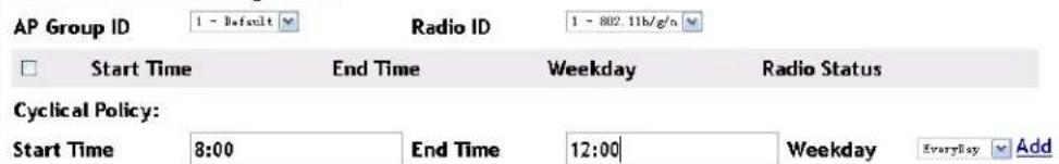
text_image
AP Group ID 1 - Refault Radio ID 1 - 802.11b/g/n Start Time End Time Weekday Radio Status Cyclical Policy: Start Time 8:00 End Time 12:00 Weekday EveryDay AddClick "add" to complete it.
Radio TimeLimit Configuration

text_image
AP Group ID 1 - Default Radio ID 1 - 802.11b/g/n Start Time End Time Weekday Radio Status 08:00 12:00 EveryDay DownExample:
Configure the radio 1 status under the profile1 as "up" from 8:00 on May 13, 2013 to 8:00 on May 14, 2013.
UTC Policy:
Start Time
2013-5-13 8:00
2013-5-14 8:00
Radio Status Up Add
Delete
Click "add" to complete it.
Radio TimeLimit Configuration
| AP Group ID | 1 - Default | Radio ID | 1 - 802.15V/g/a | |||
| □ | Start Time | End Time | Weekday | Radio Status | ||
| □ | 2013-05-13 08:00 | 2014-05-14 08:00 | Up | |||
| Cyclical Policy:Start Time hhh:mm End Time hh:mm Weekday Everyday AddUTC Policy:Start Time YYYY-MM-DD hh:mm End Time YYYY-MM-DD hh:mm Radio Status Down Add Delete | ||||||
Choose the configured policy and click "delete" button to delete the policy.
Chapter 16 Organization Unique Identifier (OUI)
16.1 Add OUI
Click WLAN configuration→advanced config→OUI; add the OUI value in the box and the format is xx-xx-xx. Add the OUI description in the second box and click "add" button as below:

text_image
OUI OUI Value OUI Description OUI Value OUI Description Add Delete16.2 Delete OUI
Click WLAN configuration→WLAN advanced config→OUI; select the OUI which needs to be deleted and click "delete" button as below:

text_image
OUI □ OUI Value OUI Description □ 00-00-01 main □ 00-00-02 office OUI Value __OUT Description ____ AddChapter 17 Trap and Syslog
Click "WLAN configuration->advanced config->trap and syslog" to enter into the trap and syslog configuration page for the SNMP and syslog configuration.
17.1 SNMP Traps
Before enabled SNMP trap, configure the SNMP management to enable the on-off function.
In the tab of management->SNMP configuration->SNMP management, select "open" for the SNMP agent state and click "apply" to enable the SNMP management on-off.
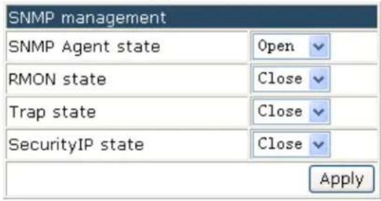
text_image
SNMP management SNMP Agent state Open RMON state Close Trap state Close SecurityIP state Close Apply17.1.1 Wireless Global Traps
In the section of SNMP trap configuration, select to enable the wireless global traps on or off.
Wireless SNMP Trap Configuration
Attention: config related service in [Management]·[SNMP configuration].
Wireless Global Traps
Enable
Wireless Status Traps
Disable
AP Failure Traps
Disable
Client Failure Traps
Disable
Peer Switch Traps
Disable
Rogue AP Traps
Disable
WIDS Status Traps
Disable
Wireless Attack Traps
AP State Change Traps
Client State Change Traps
RF Scan Traps
TSPEC Traps
Disable
Disable
Disable
Disable
Disable
Click "submit" to save the configuration. Each wireless trap will be effective only after the wireless global traps on-off is enabled. You can view the configuration on the network management tab.
17.1.2 Captive Portal
Enable the captive portal global traps before enabled the rest of the options.


After configured, select "submit" to save the configuration. You can view the traps information on the network management tab.
17.2 Syslog Configuration
View the syslog information on the server through the syslog configuration section.
17.2.1 Wireless Syslog Configuration
In the following wireless syslog configuration, select to enable or disable the wireless syslog on-off:
Wireless Syslog Configuration

text_image
AP Failure Syslogs Client Failure Syslogs Peer Switch Syslogs TSPEC Syslogs Wireless Status Syslogs Disable Disable Disable Disable Disable Disable Disable Disable Disable Disable Disable Disable Disable Disable Disable Disable Disable Disable Disable Disable Disable Disable Disable Disable Disable Disable Disable Disable Disable Disable Disable Disable Disable Disable Disable Disable Disable Disable Disable Disable Disable Disable Disable Disable Disable Disable Disable Disable Disable Disable SubmitAfter configured, select "submit" to save the configuration. You can view the configured wireless syslog on the syslog server section..
17.2.2 Captive Portal Syslog Configuration
In the captive portal syslog configuration, select to enable or disable each option of the captive portal syslog.
Captive Portal Syslog Configuration


After configured, select "submit" to save the configuration. You can view the enabled captive portal syslog on the syslog server section.
Chapter 18 Monitor
Click "monitor" to view the AC, AP, wireless client and the RF scan.
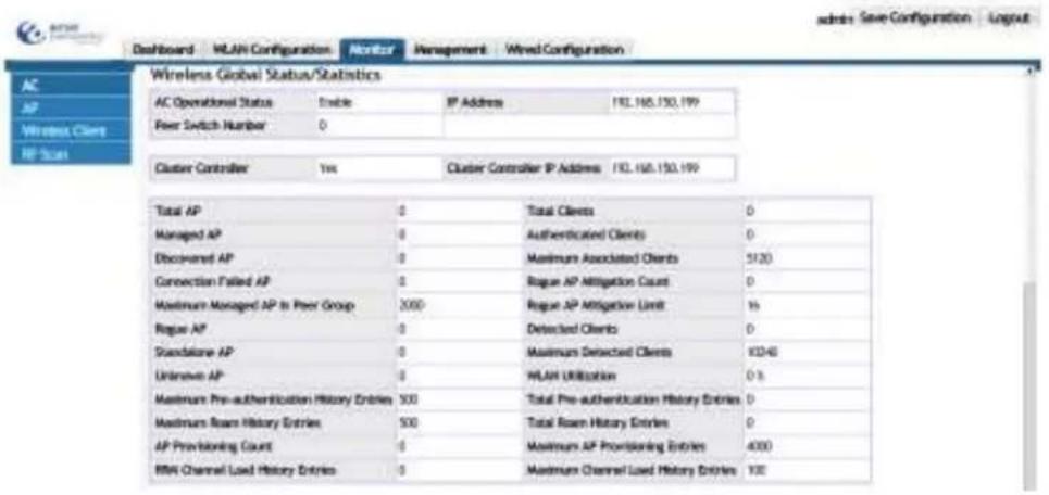
text_image
Dashboard WLAN Configuration Monitor Management Wired Configuration Wireless Global Status/Statistics AC Operational Status Enable IP Address 192.165.150.199 Peer Switch Number 0 Cluster Controller Yes Cluster Controller IP Address 192.165.150.199 Total AP Total Clients 0 Managed AP Authenticated Clients 0 Discovered AP Maximum Associated Clients 5120 Connection Failed AP Rogue AP Mitigation Count 0 Maximum Managed AP in Peer Group 2000 Rogue AP Mitigation Limit 16 Rogue AP Detected Clients 0 Standalone AP Maximum Detected Clients 8346 Unknown AP WLAN Utilization 0.3 Maximum Pre-authentication History Entries 500 Total Pre-authentication History Entries 0 Maximum Roan History Entries 500 Total Roan History Entries 0 AP Provisioning Count Maximum AP Provisioning Entries 4000 RNA Channel Load History Entries Maximum Channel Load History Entries 10018.1 AC
Click monitor->AC to enter into the AC monitoring page to monitor the cluster, status/statistics.
18.1.1 Cluster
Click monitor->AC to enter into the AC monitoring page to view the cluster information including AC operational status, cluster controller, basic information, global statistics, distributed tunnel statistics, TSPEC status and TSPEC statistics.
Wireless Global Status/Statistics
| AC Operational Status | Enable | IP Address | 20.1.1.1 |
| Peer Switch Number | 0 | ||
| Cluster Controller | Yes | Cluster Controller IP Address | 20.1.1.1 |
| Total AP | 1 | Total Clients | 0 |
| Managed AP | 1 | Authenticated Clients | 0 |
| Discovered AP | 0 | Maximum Associated Clients | 3960 |
| Connection Failed AP | 0 | Rogue AP Mitigation Count | 0 |
| Maximum Managed AP in Peer Group | 132 | Rogue AP Mitigation Limit | 16 |
| Rogue AP | 0 | Detected Clients | 606 |
| Standalone AP | 0 | Maximum Detected Clients | 7920 |
| Unknown AP | 125 | WLAN Utilization | 0% |
| Maximum Pre-authentication History Entries | 500 | Total Pre-authentication History Entries | 0 |
| Maximum Roam History Entries | 500 | Total Roam History Entries | 0 |
| AP Provisioning Count | 1 | Maximum AP Provisioning Entries | 264 |
| RRM Channel Load History Entries | 0 | Maximum Channel Load History Entries | 100 |
| WLAN Bytes Transmitted | 360 | WLAN Packets Transmitted | 1 |
| WI AN Bytes Received | 692 | WI AN Packets Received | 2 |
| WLAN Bytes Transmit Dropped | 140330004 | WLAN Packets Transmit Dropped | 108301 |
| WLAN Bytes Receive Dropped | 0 | WLAN Packets Receive Dropped | 0 |
| Distributed Tunnel Packets Transmitted | 0 | Distributed Tunnel Roamed Clients | 0 |
| Distributed Tunnel Clients | 0 | Distributed Tunnel Client Denials | 0 |
| TSPEC Status | |||
| Total Voice Traffic Streams | 0 | Total Traffic Stream Clients | 0 |
| Total Video Traffic Streams | 0 | Total Traffic Stream Roaming Clients | 0 |
| TSPEC Statistics | ||
| Access Category | Voice | Video |
| Total TSPEC Packets Received | 0 | 0 |
| Total TSPEC Packets Transmitted | 0 | 0 |
| Total TSPEC Bytes Received | 0 | 0 |
| Total TSPEC Bytes Transmitted | 0 | 0 |
| Total TSPECs Accepted | 0 | 0 |
| Total TSPECs Rejected | 0 | 0 |
| Total Roaming TSPECs Accepted | 0 | 0 |
| Total Traffic Stream Roaming Clients | 0 | 0 |
18.1.1.1 AC Operational Status
The wireless global status in cluster includes AC operational status, IP address and peer switch number. The IP address is the wireless IP address as below:
Wireless Global Status/Statistics
| AC Operational Status | Enable | IP Address | 20.1.1.1 |
| Peer Switch Number | 0 | ||
18.1.1.2 Cluster Controller
- Cluster controller—shows "yes" or "no". Yes: means that the local AC is the cluster controller; no: it means that the local AC is not the cluster controller.
- Cluster controller IP address—the wireless address of the cluster controller.
| Cluster Controller | No | Cluster Controller IP Address |
18.1.1.3 Local AC Information
The AC information includes total AP, managed AP, discovered AP, connection failed AP and maximum managed AP in peer group etc. it also includes total clients, authenticated clients, detected clients and WLAN utilization, etc. The detailed information is listed below:
| Total AP | 1 | Total Clients | 0 |
| Managed AP | 1 | Authenticated Clients | 0 |
| Discovered AP | 0 | Maximum Associated Clients | 3960 |
| Connection Failed AP | 0 | Rogue AP Mitigation Count | 0 |
| Maximum Managed AP in Peer Group | 132 | Rogue AP Mitigation Limit | 16 |
| Rogue AP | 0 | Detected Clients | 606 |
| Standalone AP | 0 | Maximum Detected Clients | 7920 |
| Unknown AP | 125 | WLAN Utilization | 0 % |
| Maximum Pre-authentication History Entries | 500 | Total Pre-authentication History Entries | 0 |
| Maximum Roam History Entries | 500 | Total Roam History Entries | 0 |
| AP Provisioning Count | 1 | Maximum AP Provisioning Entries | 264 |
| RRM Channel Load History Entries | 0 | Maximum Channel Load History Entries | 100 |
18.1.1.4 Global Statistics
The global statistics of the local AC is shown below:
| WLAN Bytes Transmitted | 8202406 | WLAN Packets Transmitted | 73457 |
| WLAN Bytes Received | 269004689 | WLAN Packets Received | 816577 |
| WLAN Bytes Transmit Dropped | 442659080 | WLAN Packets Transmit Dropped | 81658 |
| WLAN Bytes Receive Dropped | 0 | WLAN Packets Receive Dropped | 0 |
18.1.1.5 Distributed Tunnel Statistics
The distributed tunnel statistics of the local AC is shown below:
| Distributed Tunnel Packets Transmitted | 0 | Distributed Tunnel Roamed Clients | 0 |
| Distributed Tunnel Clients | 0 | Distributed Tunnel Client Denials | 0 |
18.1.1.6 TSPEC Status
The TSPEC status of the AC is shown below:
| TSPEC Status | |||
| Total Voice Traffic Streams | 0 | Total Traffic Stream Clients | 0 |
| Total Video Traffic Streams | 0 | Total Traffic Stream Roaming Clients | 0 |
18.1.1.7 TSPEC Statistics
The TSPEC statistics of the AC is shown below:
| TSPEC Statistics | ||
| Access Category | Voice | Video |
| Total TSPEC Packets Received | 0 | 0 |
| Total TSPEC Packets Transmitted | 0 | 0 |
| Total TSPEC Bytes Received | 0 | 0 |
| Total TSPEC Bytes Transmitted | 0 | 0 |
| Total TSPECs Accepted | 0 | 0 |
| Total TSPECs Rejected | 0 | 0 |
| Total Roaming TSPECs Accepted | 0 | 0 |
| Total Traffic Stream Roaming Clients | 0 | 0 |
18.1.2 Each AC Status/Statistics
Click monitor->AC to enter into the AC monitoring page to view each AC status/statistics including AC selection list, basic AC information, AC statistics, TSPEC status and TSPEC statistics.
Each AC Status/Statistics
20.1.1.1
| Total AP Count | 1 | Total Clients | 0 |
| Managed AP | 1 | Authenticated Clients | 0 |
| Discovered AP | 0 | IP Address | 20.1.1.1 |
| Connection Failed AP | 0 | Cluster Priority | 1 |
| Maximum Managed AP | 2 | Distributed Tunnel Clients | 0 |
| WLAN Utilization | 0 % | AP Image Download Mode | Integrated, Independent |
| WLAN Bytes Transmitted | 360 | WLAN Packets Transmitted | 1 |
| WLAN Bytes Received | 692 | WLAN Packets Received | 2 |
| WLAN Bytes Transmit Dropped | 140330004 | WLAN Packets Transmit Dropped | 108301 |
| WLAN Bytes Receive Dropped | 0 | WLAN Packets Receive Dropped | 0 |
TSPEC Status
| Total Voice Traffic Streams | 0 | Total Traffic Stream Clients | 0 |
| Total Video Traffic Streams | 0 | Total Traffic Stream Roaming Clients | 0 |
TSPEC Statistics
| Access Category | Voice | Video |
| Total TSPEC Packets Received | 0 | 0 |
| Total TSPEC Packets Transmitted | 0 | 0 |
| Total TSPEC Bytes Received | 0 | 0 |
| Total TSPEC Bytes Transmitted | 0 | 0 |
| Total TSPECs Accepted | 0 | 0 |
| Total TSPECs Rejected | 0 | 0 |
| Total Roaming TSPECs Accepted | 0 | 0 |
| Total Roaming TSPECs Rejected | 0 | 0 |
18.1.2.1 AC Selection List
In the AC IP address selection list, choose the IP address to view the corresponding AC status/statistics shown below:
Each AC Status/Statistics
20.1.1.1
18.1.2.2 Basic AC Information
The basic AC information includes total AP count, managed AP, discovered AP, connection failed AP, maximum managed AP, total clients, cluster priority, AP image
download mode and WLAN utilization. as shown below:
| Total AP Count | 1 | Total Clients | 0 |
| Managed AP | 1 | Authenticated Clients | 0 |
| Discovered AP | 0 | IP Address | 20.1.1.1 |
| Connection Failed AP | 0 | Cluster Priority | 1 |
| Maximum Managed AP | 2 | Distributed Tunnel Clients | 0 |
| WLAN Utilization | 0% | AP Image Download Mode | Integrated, Independent |
18.1.2.3 AC Statistics
The AC statistics is shown below:
| WLAN Bytes Transmitted | 360 | WLAN Packets Transmitted | 1 |
| WLAN Bytes Received | 692 | WLAN Packets Received | 2 |
| WLAN Bytes Transmit Dropped | 140330004 | WLAN Packets Transmit Dropped | 108301 |
| WLAN Bytes Receive Dropped | 0 | WLAN Packets Receive Dropped | 0 |
18.1.2.4 TSPEC Status
The TSPEC status is shown below:
| TSPEC Status | |||
| Total Voice Traffic Streams | 0 | Total Traffic Stream Clients | 0 |
| Total Video Traffic Streams | 0 | Total Traffic Stream Roaming Clients | 0 |
18.1.2.5 TSPEC Statistics
The TSPEC statistics is as below:
| TSPEC Statistics | ||
| Access Category | Voice | Video |
| Total TSPEC Packets Received | 0 | 0 |
| Total TSPEC Packets Transmitted | 0 | 0 |
| Total TSPEC Bytes Received | 0 | 0 |
| Total TSPEC Bytes Transmitted | 0 | 0 |
| Total TSPECs Accepted | 0 | 0 |
| Total TSPECs Rejected | 0 | 0 |
| Total Roaming TSPECs Accepted | 0 | 0 |
| Total Roaming TSPECs Rejected | 0 | 0 |
18.2 AP
Click monitor->AP to enter into the AP monitoring page to monitor the basic AP information, details, and the failed authentication AP list. You can also delete a failed managed AP.
text_image
AP Search Fields AISC Address (*)-Peer Managed 00-03-08 24:73:28 00-01-08 11:05:46 Location IP Address AP Group Software Version Status Configuration Status Age Front 192.168.158.04 1 - Default 2.0.5.36 Managed Success 04:00:00:05 Back 192.168.158.53 1 - Default 2.0.5.37 Managed Success 04:00:00:05 User OutCall Dataca Delete AK Refresh18.2.1 Basic AP Information
The basic AP information includes MAC address (*)-Peer managed, location, IP address, AP group, software version, status, configuration status and age as shown below:

text_image
AP □ MAC Address(*)-Peer ManagedLocationIP Address AP Group Software VersionStatus Configuration Status Age 00-03-0f-20-80-40 192.168.100.12 - Default 2.0.3.39 Managed Success 0d:00:00:02 □ 00-03-0f-2B-51-8c 192.168.100.21 - Default 1.0.1.42 Failed Not Start 0d:22:15:55 ViewDetail Delete Delete All RefreshExample:
- Select the failed managed AP and click "delete" to delete the failed managed AP.
- Select the "MAC address (*)-Peer managed" and click "delete" to delete all the failed managed APs.
18.2.2 AP Detail
Click the "view detail" of the monitor->AP page to view the AP detail which includes managed AP status, radio detail, neighbor APs, neighbor clients, VAP, VAP TSPEC and distributed tunneling status. Click "view detail" again or click "cancel" button to quit the AP detail page.
18.2.2.1 Managed AP Status
In the managed AP MAC address selection list, choose the MAC address and view the corresponding AP status detail. The managed AP status includes IP address, managing AC, status, configuration status, authenticated clients, CPU usage and TSPEC status etc. It is shown below:
Managed AP Status
| Managed AP Status | |||
| IP Address | 50.1.1.1 | Managing AC | Local Switch |
| IP Subnet Mask | 255.255.255.0 | AC MAC Address | 00-03-0F-00-10-00 |
| Status | Managed | AC IP Address | 20.1.1.1 |
| Software Version | 2.0.3.42 | AP Group | 1 - Default |
| Code Download Status | Not Started | Discovery Reason | AC IP Configured |
| Configuration Status | Success | Protocol Version | 2 |
| Vendor ID | AMER NETWORKS | Authenticated Clients | 1 |
| Hardware Type | WAP33DC Indoor Dual Radio a/n, b/g/n | System Up Time | 1d:19:11:27 |
| Serial Number | Age | 0d:00:00:00 | |
| CPU Type | AR9344-533 | CPU Usage(%-5s) | 9 |
| CPU Usage(%-30s) | 11 | CPU Usage(%-5min) | 10 |
| Memory Size Total(KB) | 112672 | Memory Size Used(KB) | 23820 |
| TSPEC Status | |||
| Type | Voice | Video | |
| Number of Active Traffic Streams | 0 | 0 | |
| Number of Traffic Stream Clients | 0 | 0 | |
| Number of Traffic Stream Roaming Clients 0 | 0 | ||
In the AP MAC address list, choose the corresponding MAC address and click the "reset" button, a pop-up box will appear, click "Yes" to complete the resetting configuration.

text_image
Windows Internet Explorer Are you sure to reset this managed AP? Yes Cancel18.2.2.2 Radio Detail
Radio detail includes supported channels, channel, authenticated clients, channel bandwidth, fixed channel indicator, fixed power indicator, manual channel adjustment status, manual power adjustment status, WLAN utilization (%), total neighbors and TSPEC status etc.
Click radio selection button and choose Radio1 and Radio 2 to monitor their status as shown below:
1-off 2-802.11a/n
Radio 1 detail is as below:
| Radio Detail | |||
| Supported Channels | 1, 2, 3, 4, 5, 6, 7, 8, 9, 10, 11, 12, 13 | ||
| Channel | 11 | Authenticated Clients | 0 |
| Channel Bandwidth | 20 MHz | Transmit Power | 100 |
| Fixed Channel Indicator | no | Fixed Power Indicator | no |
| Manual Channel Adjustment Status | Not Started | Manual Power Adjustment Status | Not Started |
| WLAN Utilization(%) | 0 | Total Neighbors | 312 |
| Radio Resource Measurement | Enable | ||
| TSPEC Status | |||
| Access Category | Voice | Video | |
| Operational Status | Disable | Disable | |
| Number of Active Traffic Streams | 0 | 0 | |
| Number of Traffic Stream Clients | 0 | 0 | |
| Number of Traffic Stream Roaming Clients | 0 | 0 | |
| Medium Time Admitted | 0 | 0 | |
| Medium Time Unallocated | 0 | 0 | |
| Medium Time Roaming Unallocated | 0 | 0 | |
Radio 2 detail is as below:
| Radio Detail | |||
| Supported Channels | 149, 157 | ||
| Channel | 157 | Authenticated Clients | 0 |
| Channel Bandwidth | 40 kHz | Transmit Power | 100 |
| Fixed Channel Indicator | no | Fixed Power Indicator | no |
| Manual Channel Adjustment Status | Not Started | Manual Power Adjustment Status | Not Started |
| WLAN Utilization(%) | 0 | Total Neighbors | 31 |
| Radio Resource Measurement | Enable | ||
| TSPEC Status | |||
| Access Category | Voice | Video | |
| Operational Status | Disable | Disable | |
| Number of Active Traffic Streams | 0 | 0 | |
| Number of Traffic Stream Clients | 0 | 0 | |
| Number of Traffic Stream Roaming Clients | 0 | 0 | |
| Medium Time Admitted | 0 | 0 | |
| Medium Time Unallocated | 0 | 0 | |
| Medium Time Roaming Unallocated | 0 | 0 | |
18.2.2.3 Neighbor APs
AP can detect the surrounding RF real-time including neighboring APs and neighboring clients. The neighboring APs' information is as shown below:
| Neighbor APs | ||||
| Neighbor AP MAC | SSID | RSSI | Status | Age |
| 00-03-07-03-66-10 | nd | 16 | Unknown | 06:22:20:01 |
| 00-03-07-08-09-50 | selfirm_auto_test7 | 7 | Unknown | 06:00:15:18 |
| 00-03-07-10-30-50 | test_uwrf | 31 | Unknown | 06:00:35:04 |
| 00-03-07-10-30-51 | test_uwrf | 31 | Unknown | 06:00:04:51 |
| 00-03-07-10-30-52 | uwrf1003 | 32 | Unknown | 06:00:15:18 |
Neighbor AP MAC—detected AP MAC
SSID—SSID of AP network
RSSI—received signal strength indication of AP
Status—includes Managed, Standalone (fat AP), Unknown and Rogue.
18.2.2.4 Neighbor Clients
The neighbor clients' information is as shown below:
| Neighbor Clients | ||||
| Neighbor Client MAC | RSSI | Channel | Discovery Reason | Age |
| 00-0d-0a-30-95-2d | 13 | 157 | RF | 0d:00:00:27 |
| 00-0d-0a-30-95-ee | 6 | 157 | RF | 0d:00:15:18 |
| 00-0d-0a-30-9a-26 | 6 | 157 | RF | 0d:00:03:12 |
| 00-0d-0a-30-9a-6a | 41 | 157 | Assoc Managed AP, RF | 0d:22:20:01 |
| 00-0d-a3-13-30-1a | 7 | 157 | RF | 0d:01:08:29 |
18.2.2.5 VAP
VAP detail includes VAP ID, VAP mode, BSSID, SSID and client authentications as shown below:
| VAP | ||||
| VAP ID | VAP Mode | BSSID | SSID | Client Authentications |
| 0 | Enable | 00-03-0f-20-80-50 | hfx-net1 | 0 |
| 1 | Disable | 00-03-0f-20-80-51 | hfx-net2 | 0 |
| 2 | Disable | 00-03-0f-20-80-52 | hfx-net3 | 0 |
| 3 | Disable | 00-03-0f-20-80-53 | hfx-net4 | 0 |
| 4 | Disable | 00-03-0f-20-80-54 | Managed SSID 5 | 0 |
| 1 ≥ 3 ≤ | ||||
18.2.2.6 VAP TSPEC
Choose the VAP ID in the selection list to view the corresponding TSPEC status of VAP as shown below:
| VAP TSPEC | ||
| VAP IDs ▼TSPEC Status | ||
| Type | Voice | Video |
| Operational Status | Disable | Disable |
| Number of Active Traffic Streams | 0 | 0 |
| Number of Traffic Stream Clients | 0 | 0 |
| Number of Traffic Stream Roaming Clients | 0 | 0 |
| Medium Time Admitted | 0 | 0 |
| Medium Time Unallocated | 0 | 0 |
| Medium Time Roaming Unallocated | 0 | 0 |
18.2.2.7 Distributed Tunneling Status
Distributed tunneling status includes clients using AP as home, multicast replication, clients using AP as associate, VLAN with max multicast replication and distributed tunnels (including Home AP terminal and Association AP terminal).
text_image
Distributed Tunneling Status Clients using AP as Home 0 Multicast Replications 0 Clients using AP as Associate 0 VLAN with Max Multicast Replications 0 Distributed Tunnels 0 Cancel18.2.3 Failure AP List
The failure AP list is used to show the failed authentication AP details. If the AC is the cluster controller, the failed authentication AP information of other AC in the cluster will also be shown. To distinguish, there is a “*” before the failed authentication of an AP.

text_image
Failure AP List MAC Address(*) Peer Managed IP Address Last Failure Type Age 00-03-01-20 80-40 192.168.100.1 No Database Entry 00:00:00:23 Delete All Manage RefreshClick "delete all" button to delete all failed APs from the list.
Select the failure AP list and click "managed" button. There will be a pop up box, click "OK" and this AP will be configured as the effective managed AP with the default profile; and it will be managed the next time the ac discovers it.
18.3 Wireless Client
Click monitor->Wireless Client to configure the associated and detected clients' information.

text_image
Associated Client Unit IaaS Field IP Address Cy-Park Associated ID: 01-14-04 75-59 ID: 01-01-05 68-67 Detected IP Address F12.168.158.37 F12.168.158.37 Missing Missing ISO-01-05.24.23-03 ISO-01-05.24.23-05-40 ISO-01-05.24.23-05-40 AC IP Address LAN: 150.00 LAN: 150.00 Channel Date Network Time JunctionLabel AuthenticLabel 26/08 14:45 View Default - Statusable - Statusable Ad - Network
text_image
Detected Client List AAS ADDRESS Client Name Client Status Time Since Entry Last Up/End Create Time 01-03-22 19:46:54 01-03-05 01:36:54 01-03-06 01:34:54 01-03-28 27:46:54 01-03-28 27:46:54 01-03-28 27:46:54 01-03-28 27:46:54 01-03-28 27:46:54 01-03-28 27:46:54 01-03,48 01:36:54 01-03,74 01:36:54 01-03,74 01:36:54 01-03,74 01:36:54 1.2.3.4.3.5.2.5.5.5.5.5.5.5.5.5.5.5.5.5.5.5.5.5.5.5.5.5.5.5.5.5.5.5.5.5.5.5.5.5.5.5.5.5.5.5.5.5.5.5.5.5.5.5.5.5.5. New Date Status Status #k AInchungs BInchungs M Injusus BInchungs18.3.1 Associated Client List
The associated client list shows the information of the associated clients including:
- MAC address: Show the client's MAC address (MAC address shown with a *
represent the address of the associated client on the peer switch).
- Detected IP address: Show the IP address of the client.
- NETBIOS name: the name of the client under the NETBIOS protocol
- SSID: It means the network name.
- BSSID: It is the MAC address of the associated VAP.
- AC IP address: It is the IP address of the managed AC.
- Channel: the channel that the client communicates with the AP
■ State: It means the current authentication state of the client. - Network time: It is the interval from the client connecting to the network to current.
Click "view detail" button to view the associated clients' details which are shown in the next section. Click "disassociate" button to disassociate the current selected client; click "disassociate all" to disassociate all the clients. Click "refresh" button to refresh the list.
Example: Select the client which needs to be disassociated and click "disassociate" and then click "refresh" button. The client will be disassociated.
text_image
Associated Client List MAC Address Detected NetBIOS Name SSID BSSID AC IP Address ChannelState Network Time (*)-Peer AssociatedIP Address 24-ab-81-6f-df-d8 100.1.1.5 luty_web 00-03-0f-1e-58-60 20.1.1.1 1 Authenticated 0d:00:00:23 ViewDetail Disassociate Disassociate All Refresh18.3.2 Associated Client Detail
Click "view detail" button to view the associated clients' details. Choose the client in the drop-down list and then click "view detail". Click "cancel" button below to close the detail.
18.3.2.1 Associated Client Status
Click the MAC address drop-down box and choose one client. It will show the associated client status including the basic information as below:

text_image
Associated Client Detail Associated Client Status MAC Address: '10-44-76-85-51-19 SSID web Associating AC Local Switch BSSID 00-03-0f-1e-58-60 AC MAC Address 00-03-0f-00-10-00 AP Mac Address 00-03-0f-1e-58-60 AC IP Address 20.1.1.1 State Authenticated Location Channel 6 Radio 1-802.11b/g/n User Name WLAN 1 Inactive Period 0d:00:00:00 Transmit Data Rate 58 Mbps Time Since Entry Last Updated 0d:00:00:05 Network Time 1d:20:51:16 Dot11n Capable Yes STBC Capable No NetBIOS Name 2B2ADE26D32 Detected 50.1.1.4 Tunnel IP Address DisassociateClick "disassociate" button to disassociate the client.
18.3.2.2 Associated Client's QoS Status
If the network that the client associated with is using QoS, the client's QoS status can be viewed as seen below:
| Associated Client's QoS Status | |
| Actual RADIUS (Cached) | |
| Client QoS Operational Status | enable |
| Bandwidth Limit Down | 0 |
| Bandwidth Limit Up | 0 |
| Access Control Down | 0 |
| Access Control Up | 1 |
| Diffserv Policy Down | |
| Diffserv Policy Up | |
18.3.2.3 Associated Client's Neighbor AP Status
The associated client's neighbor AP is the neighbor AP that the client scan detected. As below, this process only scans the AP associated with the controller and does not scan any other AP:
| Associated Client's Neighbor AP Status | |||
| AP MAC Address | Location | Radio | Discovery Reason |
| 00-03-0f-03-66-00 | 2-802.11a/n | Assoc Managed AP | |
18.3.3 Detected Client List
The detected client includes the client associated with AP and the scanned client. The detected client list is as shown below:
text_image
Detected Client List MAC Address Client Name Client Status Age Create Time 00-04-23-96-6b-92 Detected 0d:00:10:08 0d:00:20:02 00-08-ca-c7-fd-f9 Detected 0d:00:21:08 0d:00:21:41 00-0d-0a-30-99-2d Detected 0d:00:00:13 0d:00:32:08 00-0d-0a-30-99-ee Detected 0d:00:00:13 0d:00:32:08 00-0d-0a-30-9a-26 Detected 0d:00:00:13 0d:00:31:35 1 2 3 4 5 6 7 8 9 10 Next ViewDetail Delete Delete All Acknowledge Acknowledge All Rogues RefreshChoose one client and click "view detail" button to view the client detail status. Choose one client and click "delete" button to delete this client; click "delete all" button to delete all the detected clients, the associated clients will not be deleted. Choose the rogue client and click "acknowledge" button to clear this rogue client; click "acknowledge all rogues" to clear all the rogue clients.
18.3.4 Detected Client Detail
Click "view detail" button in the above figure to view the detected client detail.
18.3.4.1 Detected Client Status
Choose the client in the MAC address drop-down box and it will show the detected client status as below:
| MAC Address: 00-01-23-96-6b-92 | |||
| Detected Client Status | |||
| MAC Address | 00-04-23-96-6b-92 | Auth Msgs Recorded | 0 |
| Client Status | Detected | Auth Collection Interval | 0d:00:00:04 |
| Authentication Status | Not Authenticated | Highest Auth Msgs | 0 |
| Threat Detection | Not Detected | De-Auth Msgs Recorded | 0 |
| Threat Mitigation Status | Not Done | De-Auth Collection Interval | 0d:00:00:04 |
| Time Since Entry Last Updated | 0d:00:20:27 | Highest De-Auth Msgs | 0 |
| Time Since Entry Create | 0d:00:52:56 | Authentication Failures | 0 |
| Client Name | Probes Detected | 0 | |
| RSSI | 15 | Broadcast BSSID Probes | 0 |
| Signal | -80 | Broadcast SSID Probes | 0 |
| Noise | -95 | Specific BSSID Probes | 0 |
| Probe Req Recorded | 0 | Specific SSID Probes | 0 |
| Probe Collection Interval | 0d:00:00:04 | Last Non-Broadcast BSSID | 00-00-00-00-00-00 |
| Highest Probes Detected | 2 | Last Non-Broadcast SSID | |
| Channel | 2 | Threat Mitigation Sent | 0d:00:00:00 |
| Assoc Collection Interval | 0d:00:00:04 | DisAssoc Collection Interval | 0d:00:00:04 |
| Assoc Msgs Recorded | 0 | DisAssoc Msgs Recorded | 0 |
| OUI Description | Intel Corporation | ||
| Acknowledge | |||
If this client is rogue, click "acknowledge" button to clear this client.
18.3.4.2 WIDS Client's Rogue Classification
For the selected clients, the WIDS client's rogue classification can show the rogue classification status of this client as listed below:
| WIDS Client's Rogue Classification | ||||||
| Test Description | Condition Reporting Detected MAC Address | Radio | Test Config | Test Result | Time Since First Report | Time Since Last Report |
| Client not in Known Client Database | false | 00-00-00-00-00-00 0 | Disable | 0d:01:07:16 | 0d:01:07:16 | |
| Client exceeds configured rate for auth msgs | false | 00-03-0f-03-66-00 1 | Enable | 0d:01:07:16 | 0d:00:20:27 | |
| Client exceeds configured rate for probe msgs | false | 00-03-0f-03-66-00 1 | Enable | 0d:01:07:16 | 0d:00:20:27 | |
| Client exceeds configured rate for de-auth msgs | false | 00-03-0f-03-66-00 1 | Enable | 0d:01:07:16 | 0d:00:20:27 | |
| Client exceeds max failing authentications | false | 00-03-0f-03-66-00 1 | Enable | 0d:01:07:16 | 0d:00:20:27 | |
| WIDS Client's Rogue Classification | ||||||
| Test Description | Condition | Reporting | Radio | Test | Test | Time Since Time Since |
| Detected | MAC Address | Config | Result | First Report Last Report | ||
| Known client authenticated with unknown AP | false | 00-00-00-00-00-00 0 | Disable | 0d:01:07:16 | 0d:01:07:16 | |
| Client OUI not in the OUI Database | false | 00-00-00-00-00-00 0 | Disable | 0d:01:07:16 | 0d:01:07:16 | |
| Client exceeds configured rate for assoc msgs | false | 00-03-0f-03-66-00 1 | Enable | 0d:01:07:16 | 0d:00:20:27 | |
| Client exceeds configured rate for disAssoc msgs | false | 00-03-0f-03-66-00 1 | Enable | 0d:01:07:16 | 0d:00:20:27 | |
12
- Test description: detail WIDS client's rogue classification
- Condition detected: "false" means that this item does not meet the rogue detection condition; "true" means that this rogue detection is determined and it is the rogue client.
- Reporting MAC address: It means the AP which reports the information. If the mac address is 0 for all digits, it means that no AP reports the test item of this client.
18.3.4.3 Detected Client's Pre-authentication History
If the detected client has the authentication history, it can show the information as listed below:

text_image
Detected Client's Pre-Authentication History MAC Address AP MAC Address VAP MAC Address SSID Time Since Event User Name Pre-Authentication Status Clean History18.3.4.4 Detected Client's Triangulation
| Detected Client's Triangulation | ||||||
| Sentry | MAC Address | Radio | RSSI(%) | Signal Strength (dBm) | Noise Level (dBm) | Age |
| No Sentry | c0-cb-38-3e-1a-6d | 2 | 59 | -36 | -95 | 0d:00:00:23 |
| No Sentry | c0-cb-38-3e-1a-6d | 1 | 28 | -67 | -95 | 0d:00:00:23 |
18.3.4.5 Detected Client's Roam History
The detected client's roam history can show the roam history of the client which is being associated or which had been associated but no longer connected. The following figure shows the roam history of the client whose mac is c0-cb-38-3e-1a-6d:
| Detected Client's Roam History | |||||
| MAC Address | AP MAC Address | VAP MAC Address | SSID | Age | |
| c0-cb-38-3e-1a-6d | 00-03-0f-03-66-00 | 1 00-03-0f-03-66-00 | nd | Roaming | 0d:00:00:42 |
| Clean History | |||||
- The AP MAC is the one of the current AP that the client roams to.
18.4 RF Scan
Click monitor->RF scan to enter into the RF scan page. It includes AP RF scan status and client dynamic blacklist.
18.4.1 AP RF Scan Status
AP RF scan status shows all the APs' information as shown below:
AP RF Scan Status
| MAC Address | SSID | Physical Mode | Channel | Status | Age |
| 00-01-7a-f6-c4-c0 | test_open | B02.11b/g | 11 | Unknown | 0d:00:03:49 |
| 00-01-7a-f6-c4-c2 | wlan_test_wpa2 | B02.11b/g | 11 | Unknown | 0d:00:30:12 |
| 00-01-7a-f7-04-40 | jiayy | B02.11b/g | 6 | Unknown | 0d:00:25:49 |
| 00-01-7a-f7-0a-40 | test_open | B02.11b/g | 11 | Unknown | 0d:05:47:32 |
| 00-01-7a-f7-0a-42 | wlan_test_wpa2 | B02.11b/g | 11 | Unknown | 0d:06:05:05 |
AP RF scan status list describes all the APs' status in the wireless network and the AP monitors the RF environment including client and AP information. It will send the monitored information periodicity to the associated AC.
- MAC address: the MAC address of the scanned AP.
- SSID: the network SSID sent by the scanned AP.
■ Physical mode: the radio mode that the scanned AP works in. - Channel: the channel that the scanned AP works on.
- Status: the status of the scanned AP including unknown, managed and rogue.
■ Age: the interval from the last scanning to current.
Click "view detail" to view the RF scan status of one AP. Click "delete all" to delete all the scanned APs. Click "manage" to add the selected AP into the AP database. Click "refresh" to refresh the scan information.
18.4.2 AP RF Scan Detail
Click "view detail" in the AP RF scan status to open the detail information.
18.4.2.1 AP RF Scan Status
Choose the AP in the "AP RF Scan Detail" drop-down box and view the detail information.
AP RF Scan Detail
| AP RF Scan Status | |||
| MAC Address | 00-01-7a-f6-c4-c0 | BSSID | 00-01-7a-f6-c4-c0 |
| SSID | test open | Physical Mode | 802.11b/g |
| Channel | 11 | Security Mode | Open |
| Status | Unknown | 802.11n Mode | Support |
| Initial Status | Unknown | Beacon Interval (msecs) | 100 |
| Transmit Rate | 1 Mbps | Highest Supported Rate | 144.4 Mbps |
| WIDS Rogue AP Mitigation | Not Required | Peer Managed AP | Peer managed |
| Age | 0d:00:03:49 | Ad hoc Network | Not Ad Hoc |
| Discovered Age | 3d:21:28:10 | OUI Description | |
- MAC address: the MAC address of the scanned AP.
- BSSID: the mac of the associated VAP.
■ Physical mode: the 802.11 mode that the AP uses. - Channel: the channel that the AP transmits on.
- Security mode: includes open, wep and wpa.
- WIDS rogue AP mitigation: if the enable the mitigation has been enabled for the rogue AP.
- Age: the interval from the last scanning and reporting to current AC.
- Ad hoc network: whether it is ad hoc network.
- Discovered age: the interval from the first scanning to current AC.
- OUI description: the name of the AP's company.
18.4.2.2 AP Triangulation Status
AP triangulation status shows the neighbor AP information for AP location. The location information includes 3 radios which are not in sentry mode and 3 radios which are in sentry mode. The AP triangulation status is as shown below:
AP Triangulation Status
| Sentry | MAC Address | Radio | RSSI(%) | Signal Strength (dBm) | Noise Level (dBm) |
| No Sentry | 00-01-7a-f6-c4-c0 | 1 | 52 | -43 | -95 |
18.4.2.3 WIDS AP Rogue Classification
The scanned AP can judge if the AP is a rogue AP through WIDS. The rogue classification is as shown below:
| WIDS AP Rogue Classification | |||||||
| Status | Unknown | ||||||
| Test Description | Condition Detected Reporting MAC AddressRadio Test Config Test Result Time Since First Report Time Since Last Report | ||||||
| Administrator configured rogue AP | false | 00-00-00-00-00-00 | 0 | Enable | 0d:00:00:00 | 0d:00:00:00 | |
| Managed SSID from an unknown AP | false | 00-00-00-00-00-00 | 0 | Disable | 0d:00:00:00 | 0d:00:00:00 | |
| Managed SSID from a fake managed AP | false | 00-00-00-00-00-00 | 0 | Disable | 0d:00:00:00 | 0d:00:00:00 | |
| AP without an SSID | false | 00-00-00-00-00-00 | 0 | Disable | 0d:00:00:00 | 0d:00:00:00 | |
| Fake managed AP on an invalid channel false | 00-00-00-00-00-00 | 0 | Disable | 0d:00:00:00 | 0d:00:00:00 | ||
| WIDS AP Rogue Classification | ||||||
| Status | Unknown | |||||
| Test Description | Condition Detected Reporting MAC Address Radio Test Config Test Result Time Since First Report Time Since Last Report | |||||
| Managed SSID detected with incorrect security false | 00-00-00-00-00-00 | 0 | Disable | 0d:00:00:00 | 0d:00:00:00 | |
| Invalid SSID from a managed AP | false | 00-00-00-00-00-00 | 0 | Disable | 0d:00:00:00 | 0d:00:00:00 |
| AP is operating on an illegal channel | false | 00-00-00-00-00-00 | 0 | Disable | 0d:00:00:00 | 0d:00:00:00 |
| Standalone AP with unexpected configuration false | 00-00-00-00-00-00 | 0 | Disable | 0d:00:00:00 | 0d:00:00:00 | |
| Unexpected WIDS device detected on network false | 00-00-00-00-00-00 | 0 | Disable | 0d:00:00:00 | 0d:00:00:00 | |
| WIDS AP Rogue Classification | |||||
| Status | Unknown | ||||
| Test Description | Condition Detected Reporting MAC Address Radio Test Config Test Result Time Since First Report Time Since Last Report | ||||
| Unmanaged AP detected on wired network false | 00:00:00:00:00:00 | 0 | Disable | 0d:00:00:00 | 0d:00:00:00 |
| Administrator configured rogue SSID | false | 00:00:00:00:00:00 | 0 | Disable | 0d:00:00:00 |
If any of the above conditions are shown as true, then the scanned AP is considered to be a rogue AP.
18.4.3 Client Dynamic Blacklist
The wireless RF can report the client as a dynamic blacklist through the dynamic blacklist conditions. The scanned dynamic blacklist is as shown below:
| Client Dynamic Blacklist | ||||
| MAC Address | Life Time(seconds) | Time Since Last Report | Rogue Classification | |
| 00:27-19-ad-a8-75 | 300 | 0d:00:00:00 | Client exceeds configured rate for probe msgs | |
Click "delete" to delete the selected client; click "delete all" to delete the entire client dynamic blacklist.
Chapter 19 Management
19.1 Basic Configuration
Click management->switch basic configuration to configure the username and password, user authentication method, user security IP, clock, switch name and exec timeout; user can save the current configuration.
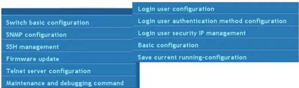
text_image
Login user configuration Switch basic configuration Login user authentication method configuration SNMP configuration Login user security IP management SSH management Basic configuration Firmware update Save current running-configuration Telnet server configuration Maintenance and debugging command19.1.1 Login Username and Password Configuration
Click management->switch basic configuration->login username and password configuration to add or delete the user information.
Example: Create a user whose name and password are both admin and set its priority to 15.
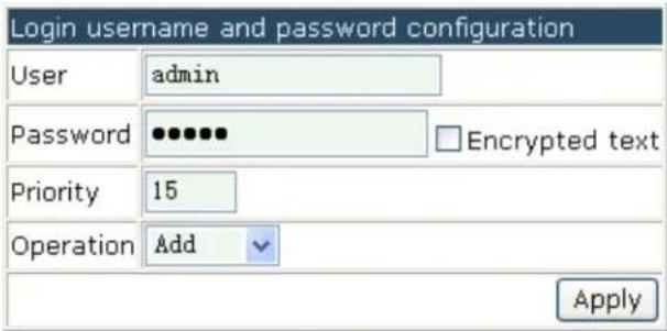
text_image
Login username and password configuration User admin Password ••••••• Encrypted text Priority 15 Operation Add ApplyClick "apply" and the added user information will be shown as below:
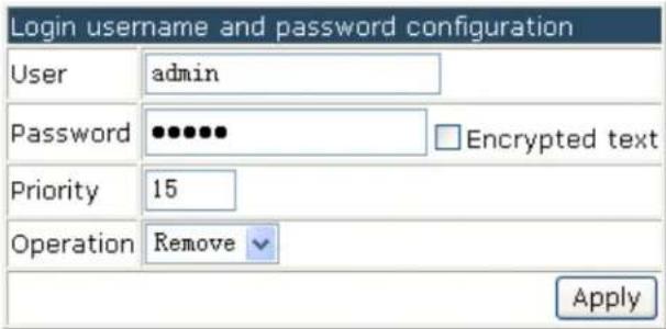
text_image
Login username and password configuration User admin Password •••••• Encrypted text Priority 15 Operation Remove Apply- Username—the appointed username
- Password—configures the appointed password
- Encrypted text—selects if show the input password
- Priority—only the user whose priority is 15 can log in the WEB management page
- Operation—includes "add" ot "delete"
19.1.2 Login User Authentication Method Configuration
Click management->switch basic configuration->login user authentication method configuration to configure the VTY (the login methods of Telnet and ssh), Web, Console methods; and configure the login user authentication method and priority.
The login methods include console, VTY (including Telnet and ssh) and Web. The authentication method must be one of local, radius and tacacs. Local means to use the local database for authentication; tacacs means to use the Tacacs+ remote authentication server for authentication; radius means to use the radius remote authentication server for authentication. There is no need to authenticate using the console method; the authentication methods of VTY and Web use local authentication as default.

text_image
Login user authentication method configuration Login method Console Authentication method1 Console Authentication method2 Vty Authentication method3 Web Authentication method4 None Authentication method4 None Apply DefaultExample: Configure a user with the radius remote authentication server for authentication usign Telnet and ssh.
Note: The corresponding user authentication method can be configured for Console, VTY and Web respectively. The authentication method can be selected using any combination of local, radius and tacacs. When using this combination authentication
methods, the priority of the first authentication method is highest and it goes in descending order. If the authentication method with higher priority passed, the user will be allowed to log in directly and the following authentication methods will be ignored.

text_image
Login user authentication method configuration Login method Vty Authentication method1 Radius Authentication method2 Local Authentication method3 Tacacs Authentication method4 Ldap Apply Default19.1.3 Login User Security IP Set
Click management->switch basic configuration->login user security IP set to configure the security IP address that a Telnet or HTTP user can access the AC from.
Before setting the security Ip address, a user can access the AC from any location. Once this setting has been enabled, a user must log in from the specified subnet only. 32 security IP addresses can be configuring on the switch.
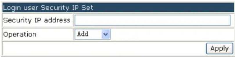
text_image
Login user Security IP Set Security IP address Operation Add ApplyExample: Configure 192.168.1.21 as the security IP address and click "apply" to complete the configuration.

text_image
Login user Security IP Set Security IP address 192.168.1.21 Operation Add Apply19.1.4 Basic Configuration
Click management->switch basic configuration->basic configuration to configure the clock, switch name and exec timeout.
- Basic clock configuration—configures the system date and time.
Example: User configures the HH:MM:SS as 10:00:00 and configures the YYYY.MM.DD as 2013.05.25. Click "apply" to complete the configuration.
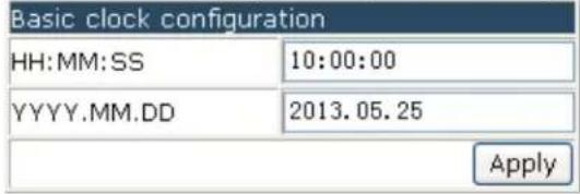
text_image
Basic clock configuration HH:MM:SS 10:00:00 YYYY.MM.DD 2013.05.25 Apply2. Configure exec timeout
Example: Configure the exec timeout as 6 minutes and 6 seconds and then click "apply" to complete the configuration.
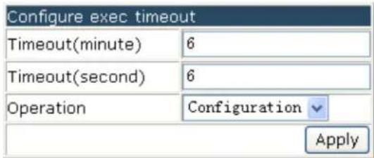
text_image
Configure exec timeout Timeout(minute) 6 Timeout(second) 6 Operation Configuration Apply3. Switch name configuration
Example: Configure the switch name as "Switch" and click "apply" to complete the configuration.
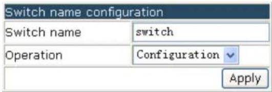
text_image
Switch name configuration Switch name switch Operation Configuration Apply19.1.5 Save Current Running-configuration
Click management->switch basic configuration->save current running-configuration to save the current configuration.
- Save current running-configuration—click "apply" to save the current configuration as below:

text_image
Save current running-configuration ApplyThere will be a pop up message after saving successfully:
Save current running-configuration succeed
- Save current configuration before reboot?—select "yes" or "no" to decide if to save the configuration. Click "apply" to make it effective and restart the switch.

text_image
Save current configuration before reboot? Yes Yes No Apply- Reboot with the default configuration—click "apply" to clear all the current configurations in the switch and restart the switch.

text_image
Reboot with the default configuration Apply19.2 SNMP Configuration
Click management->SNMP configuration to configure the SNMP function. Notice: enable the SNMP function first before you configure it.
| Switch basic configuration | SNMP authentication |
| SNMP configuration | SNMP management |
| SSH management | Community managers |
| Firmware update | Configure snmp manager security IP |
| Telnet server configuration | SNMP statistics |
| Maintenance and debugging command |
19.2.1 SNMP Authentication
Click management->SNMP configuration->SNMP authentication to configure the SNMPv3 options, including users, groups, views and SNMP engine id configuration as below:
| Switch basic configuration | SNMP authentication | Users |
| SNMP configuration | SNMP management | Groups |
| SSH management | Community managers | Views |
| Firmware update | Configure snmp manager security IP | SNMP engineid configuration |
| Telnet server configuration | SNMP statistics | |
| Maintenance and debugging command |
19.2.1.1 Users
Click management->SNMP configuration->SNMP authentication->users to add or delete the SNMPv3 users.
- SNMP username—the user name, it includes 1 to 32 characters.
-
SNMP group—the group name that the user belongs too.
-
Security level—the encryption level of the current user: noAuthNoPriv means no authentication and no privacy; AuthNoPriv means authentication but no privacy; AuthPriv means authentication and privacy.
- Authentication protocol—configures the used algorithm: MD5 or SHA.
- Authentication password—the authentication password of the current user, its length is 8 to 32 characters.
- Privacy protocol—uses the DES for packet privacy. Only when the security level is selected as AuthPriv, this item can be configured.
■ Operation—add or delete
Example: input the SNMP username as tester, input the SNMP group as UserGroup, select the security level as authPriv, select the authentication protocol as MD5, input the authentication password as hellohello, select the privacy protocol as DES, select the operation as add. Click "apply" to add the user of tester into the usergroup of UserGroup. Its security level is with privacy, it uses the HMAC md5 and its password is hellohello as below:

text_image
Users SNMP username tester SNMP group UserGroup Security level authPriv Authentication protocol: MD5 Authentication password: hellohello Privacy protocol: DES AuthPriv Password: 1234stst Ipv4 access control list acl-ipv4 Ipv6 access control list acl-ipv6 Operation Add Apply19.2.1.2 Groups
Click management->SNMP configuration->SNMP authentication->groups to add or delete the SNMPv3 groups.
- SNMP group—the user group name of SNMP, it includes 1 to 32 characters.
- Security level—the security level of the group: noAuthNoPriv means no authentication and no privacy; AuthNoPriv means authentication but no privacy; AuthPriv means authentication and privacy.
- Read SNMP view—configures the SNMP view name with the read permission.
-
Write SNMP view—configures the SNMP view name with the write permission.
-
Notify SNMP view—configures the SNMP view name with the notify permission.
■ Operation—add or delete
Example: input the SNMP group as UserGroup, select the security level as authPriv, input max in the three SNMP views, select the operation as add. Click "apply" to complete the group creation as below:
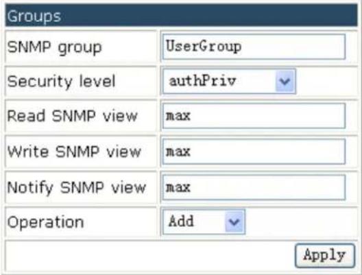
text_image
Groups SNMP group UserGroup Security level authPriv Read SNMP view max Write SNMP view max Notify SNMP view max Operation Add Apply19.2.1.3 Views
Click management->SNMP configuration->SNMP authentication->views to add or delete the SNMPv3 views.
SNMP view—configures the view name; it includes 1 to 32 characters.
OID—the OID or the corresponding node name, it includes 1 to 255 characters.
Type—configures the "include/exclude" for this OID.
Operation—add or delete.
Example: input the SNMP view as max, input the OID as 1.3.6.1.4.1.6339, select the type as "Include", and select the operation as add. Click "apply" to complete the view creation as below:

text_image
Views SNMP view max OID 1.3.6.1.4.1.6339 Type: Include Operation Add Apply19.2.1.4 SNMP Engine id Configuration
Click management->SNMP configuration->SNMP authentication->SNMP engine id configuration to configure the engine id.
- Engine id—the engine id, it includes 1 to 32 hex characters.
- Operation—configuration or default
Example: input the Engine id as 18c30125fa and select the operation as configuration. Click "apply" to complete the engine ID of 31386333303132356661 as below:

text_image
SNMP engineid configuration Engineid 18c30125fa Operation Configuration Apply Engineid 3138633330313235666119.2.2 SNMP Management
Click management->SNMP configuration->SNMP management to configure the SNMP Agent state, RMON state, Trap state and SecurityIP state.
Example: select the SNMP agent state as open; select the RMON state as open; select the Trap state as open and select the securityIP state as close. Click "apply" to complete the configuration as below:

text_image
SNMP management SNMP Agent state Open RMON state Open Trap state Open SecurityIP state Close Apply- SNMP Agent state—open/close the SNMP agent function of the switch.
■ RMON state—open/close the RMON function of the switch. - Trap state—open/close the function that the device receives the Trap information.
- SecurityIP state—open/close the security IP address checking function of the NMS management station.
19.2.3 Community Managers
Click management->SNMP configuration->community managers to configure the community string and TRAP manager.
- Community managers—configure the community string and access priority.
■ Community string (1 to 255 characters)—configures the community string. - Access priority—includes “read only” and “read and write”.
Example: configure the community string as public; select the access priority as "read
only". Click "apply" to complete the configuration as below:

text_image
Community managers Community string public Access priority Read only Operation Add Apply2. Trap manager configuration
Click management->SNMP configuration->community managers to configure the community string and the IP address which receives the SNMP trap message.
- Trap receiver—the IP address which receives the trap message
- Community string (1 to 255 characters)—Used to receive the trap message.
Example: configure the Trap receiver as 192.168.100.100; configure the community string as trap. Click "apply" to complete the configuration as below:
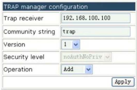
text_image
TRAP manager configuration Trap receiver 192.168.100.100 Community string trap Version 1 Security level noAuthNoPriv Operation Add Apply19.2.4 Configure SNMP Manager Security IP
Click management->SNMP configuration->configure snmp manager security IP to configure the security IP which is allowed to access the switch.
■ Security IP address—the security IP address of NMS
Example: configure the security IP address as 10.1.1.10 and click "apply" to complete the configuration as below:
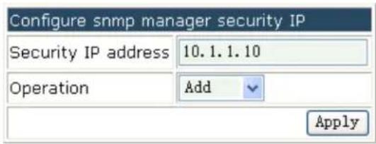
text_image
Configure snmp manager security IP Security IP address 10.1.1.10 Operation Add Apply19.2.5 SNMP Statistics
Click management->SNMP configuration->SNMP statistics to show the feedback information.
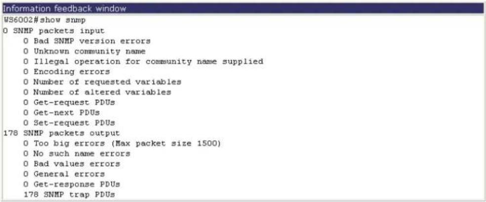
19.3 SSH Management
Click management->SSH management to configure the SSH function.
Notice: enable the SSH option before configuring it.
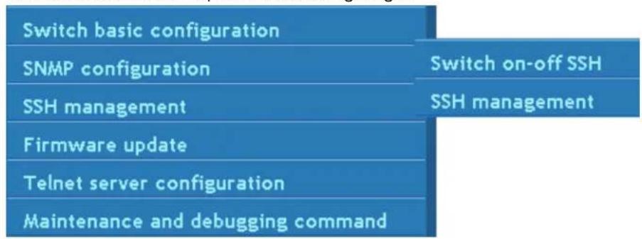
flowchart
graph TD
    A["Switch basic configuration"] --> B["SNMP configuration"]
    B --> C["SSH management"]
    C --> D["Firmware update"]
    D --> E["Telnet server configuration"]
    E --> F["Maintenance and debugging command"]
    G["Switch on-off SSH"] --> H["SSH management"]
19.3.1 Switch on-off SSH
Click management->SSH management->switch on-off SSH to enable or disable the SSH function.
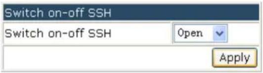
text_image
Switch on-off SSH Switch on-off SSH Open Apply19.3.2 SSH Management
Click management->SSH management->SSH management to configure the SSH timeout management, SSH reauthentication management and create an SSH RSA key.
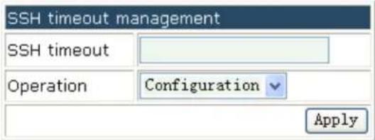
text_image
SSH timeout management SSH timeout Operation Configuration ApplySSH timeout management—configures the SSH timeout management, the range is from 10 to 600 seconds and the default value is 180s.

text_image
SSH reauthentication management SSH reauthentication Operation Configuration ApplySSH reauthentication management—configures the SSH reauthentication management, the range is from 1 to 10 and the default value is 3.
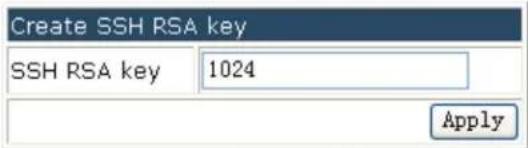
text_image
Create SSH RSA key SSH RSA key 1024 ApplyRsa key—the algorithm for the host key, the range is from 768 to 2048 and the default value is 1024.
19.4 Firmware Update
Click manage->firmware update to configure the firmware update by using TFTP service or FTP service as below:

flowchart
graph TD
    A["Switch basic configuration"] --> B["SNMP configuration"]
    B --> C["SSH management"]
    C --> D["Firmware update"]
    D --> E["Telnet server configuration"]
    E --> F["Maintenance and debugging command"]
    C --> G["TFTP service"]
    G --> H["FTP service"]
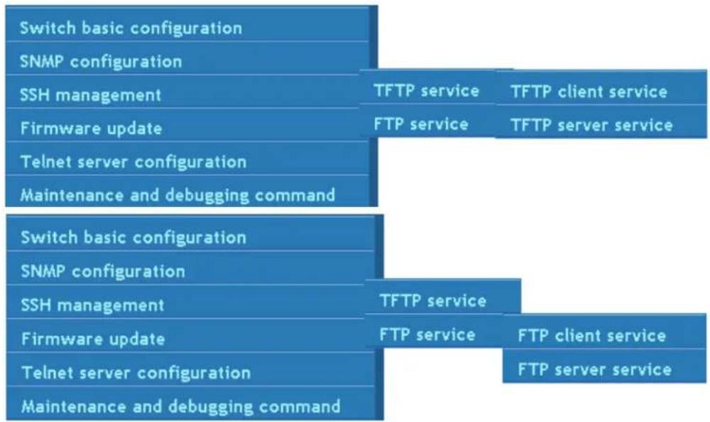
flowchart
graph TD
    A["Switch basic configuration"] --> B["SNMP configuration"]
    B --> C["SSH management"]
    C --> D["Firmware update"]
    D --> E["Telnet server configuration"]
    E --> F["Maintenance and debugging command"]

    G["Switch basic configuration"] --> H["SNMP configuration"]
    H --> I["SSH management"]
    I --> J["Firmware update"]
    J --> K["Telnet server configuration"]
    K --> L["Maintenance and debugging command"]

    M["TFTP service"] --> N["TFTP service"]
    O["TFTP client service"] --> P["TFTP server service"]

    Q["TFTP service"] --> R["FTP service"]
    S["FTP client service"] --> T["FTP server service"]
1 TFTP service includes:
- TFTP client service—Used to configure the TFTP client.
- TFTP server service—Used to configure the TFTP server.
2 FTP service includes: - FTP client service—Used to configure the FTP client.
- FTP server service—Used to configure the FTP server.
19.4.1 TFTP Client Service
Click manage->firmware update->TFTP service->TFTP client service to enter into the configuration page as below:
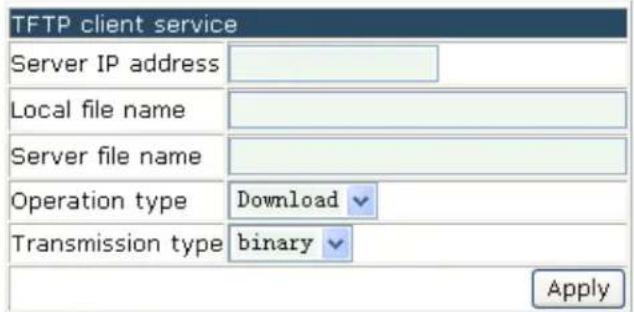
text_image
TFTP client service Server IP address Local file name Server file name Operation type Download Transmission type binary Apply■ Server IP address—the IP address of the server
- Local file name—destination file name, the range is from 1 to 100 characters.
- Server file name—source file name, the range is from 1 to 100 characters.
- Operation type—includes upload and download.
- Transmission type--"ascii" means to use ASCII to transmit the file; "binary" means to use the binary to transmit the file.
Example: get the system file whose local file name is nos.img and server file name is nos.img from the IP address of 10.1.1.10 of the TFTP server. The configuration is as below. Please click "apply" to make it effective.

text_image
TFTP client service Server IP address 10.1.1.10 Local file name nos.img Server file name nos.img Operation type Download Transmission type binary Apply19.4.2 TFTP Server Service
Click manage->firmware update->TFTP service->TFTP server service to enter into the configuration page as below:
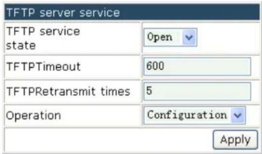
text_image
TFTP server service TFTP service state Open TFTPTimeout 600 TFTPRetransmit times 5 Operation Configuration Apply- TFTP Service state—the server state which includes OPEN and CLOSE.
■ TFTP timeout—the timeout
■ TFTP retransmit times—the times of retransmission
Example: open the TFTP service state and configure the fit TFTP timeout and TFTP retransmit times. Click "apply" to make it effective as below:
text_image
TFTP server service TFTP service state Open TFTPTimeout 600 TFTPRetransmit times 5 Operation Configuration Apply19.4.3 FTP Client Service
Click manage->firmware update->FTP service->FTP client service to enter into the configuration page as below:
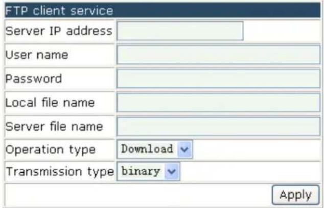
text_image
FTP client service Server IP address User name Password Local file name Server file name Operation type Download Transmission type binary Apply■ Server IP address—the IP address of the server
- User name—the user name, the range is from 1 to 100 characters.
- Password—the appointed password, the range is from 1 to 100 characters.
- Local file name—destination file name, the range is from 1 to 100 characters.
- Server file name—source file name, the range is from 1 to 100 characters.
- Operation type—includes upload and download.
- Transmission type--"ascii" means to use ASCII to transmit the file; "binary" means to use the binary to transmit the file.
Example: get the system file whose local file name is nos.img and server file name is nos.img from the IP address of 10.1.1.1 of the FTP server. The configuration is as below.
The FTP user name is admin and password is admin. Please click "apply" to make it effective.

text_image
FTP client service Server IP address 10.1.1.1 User name admin Password admin Local file name nos.img Server file name nos.img Operation type Download Transmission type binary Apply19.4.4 FTP Server Service
Click manage->firmware update->FTP service->FTP server service to enter into the configuration page. It includes FTP server service and FTP user name and password setting.
The options in FTP server service is shown below:
- FTP Service state—the server state which includes OPEN and CLOSE.
- FTP timeout—the timeout, the range is from 5 to 3600 seconds.
- Operation—includes configuration and default
The options in FTP user name and password setting is shown below:
- User name—the user name, the range is from 1 to 32 characters.
- Password—the appointed password, the range is from 1 to 16 characters.
- State—the password showing includes plain text and encrypted text. The plain text means that the input content will be shown; the encrypted text means that the input content will not be shown directly.
- Operation—includes add and delete
Example 1: configure the FTP service state as open and configure the FTP timeout as 600s. Click "apply" to complete the configuration.

text_image
FTP server service FTP service state Open FTPTimeout 600 Operation Configuration ApplyExample 2: input the user name as switch and input the password as switch, configure the state as plain text and select add for operation type. Click "apply" to complete the configuration. The configuration of the new user will be effective.
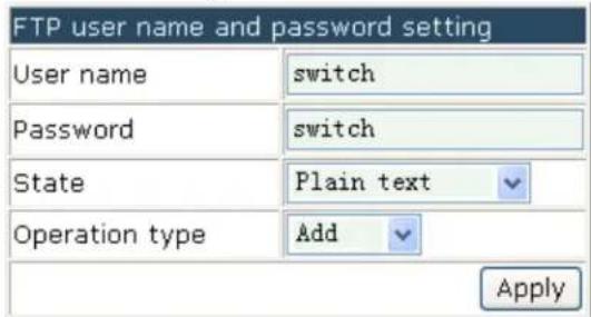
text_image
FTP user name and password setting User name switch Password switch State Plain text Operation type Add Apply19.5 Telnet Server Configuration
Click management->Telnet server configuration to configure the Telnet server state and max numbers of telnet access connection.
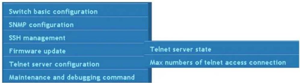
flowchart
graph TD
    A["Switch basic configuration"] --> B["SNMP configuration"]
    B --> C["SSH management"]
    C --> D["Firmware update"]
    D --> E["Telnet server configuration"]
    E --> F["Maintenance and debugging command"]
    G["Telnet server state"] --> H["Max numbers of telnet access connection"]
19.5.1 Telnet Server State
Click management->Telnet server configuration->Telnet server state to configure it.
Example: select the Telnet server state as "open" and click "apply" to start the Telnet server as below:
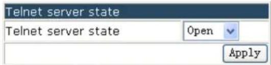
text_image
Telnet server state Telnet server state Open Apply19.5.2 Max Numbers of Telnet Access
Connection
Click management->Telnet server configuration->max numbers of Telnet access connection to configure it.
Example: configure the Telnet access connection number as 10 and click "apply" to complete the configuration.

text_image
Max numbers of telnet access connection Telnet access connection number 10 Operation Configuration Apply19.6 Maintenance and Debugging Command
Click management-> maintenance and debugging command to enter into the configuration page.
| Switch basic configuration | Debug command |
| SNMP configuration | show clock |
| SSH management | show cpu usage |
| Firmware update | show memory usage |
| Telnet server configuration | show flash |
| Maintenance and debugging command | show running-config |
| show switchport interface | |
| show tcp | |
| show udp | |
| show telnet login | |
| show version |
The content includes:
- Debug command—the connection status of the tested switch
■ show clock—shows the current time
■ show cpu usage—shows the CPU usage information under the current running status - show memory usage—shows the memory usage information under the current running status
■ show flash—shows the FLASH file information - show running-config—shows the current parameters configuration
■ show switchport interface—shows the property of the VLAN interface - show tcp—shows the TCP which is connected to the switch currently
■ show udp—shows the UDP which is connected to the switch currently - show telnet login—shows the client information which is connected to the switch
■ show version—shows the system version information of the switch
19.6.1 Debug Command
Click management->maintenance and debugging command->debug command to enter into the configuration page as below and configure the basic host configuration, PING and traceroute.
basic configuration configures the mapping between the switch and the IP address.
Example: configure the host name as switch, configure the IP address as 200.121.1.1 and click "apply" to complete the configuration as below:
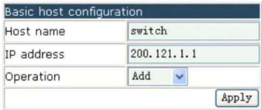
text_image
Basic host configuration Host name switch IP address 200.121.1.1 Operation Add ApplyPING
The options are below:
- Host name-name of the host
■ IP address-the destination IP address
Example: input the IP address as 192.168.1.80 and click "apply" to complete the configuration as below:
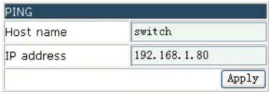
text_image
PING Host name switch IP address 192.168.1.80 ApplyTraceroute
The options are below:
■ IP address-the destination IP address
■ Host name-name of the host
- Hops—max hops that can pass
■ timeout—timeout of the packet

text_image
Traceroute IP address 200.121.1.1 Host name switch Hops 1 Timeout 100 Apply19.6.2 Others
The other configurations in "maintenance and debugging command" are just "show" commands. Click on each configuration node to get the corresponding information (they will not be listed one by one).
Example:
- Show the clock as below:

- Show the CPU usage information under the current status as below:

- Show the memory usage information under the current status as below:

- Show the FLASH file as below:
| Information feedback window | ||
| -rwx | 10.0K | 1014.cfg |
| -rwx | 48 | 123.lic |
| -rwx | 256 | boot.conf |
| -rwx | 255 | bootip.conf |
| -rwx | 245 | dh1024.pem |
| -rwx | 156 | dh512.pem |
| -rwx | 18.3K | fzhill.cfg |
| -rwx | 5.5K | hanfx.cfg |
| -rwx | 48 | license.lic |
| -rwx | 12.9M | nos.img |
| -rwx | 502.9K | nos.img.ecc |
| -rwx | 24 | portal-locale.cfg |
| -rwx | 5.2K | startup-20110619 .cfg |
| -rwx | 4.2K | startup.cfg |
| -rwx | 0 | vlan.pem |
| -rwx | 245 | wsdh1024.pem |
| -rwx | 156 | wsdh512.pem |
| -rwx | 928 | wssl2_cert.pem |
| -rwx | 887 | wssl2_key.pem |
| -rwx | 6.5K | zhangfank.cfg |
| -rwx | 11.3K | zhangpeng1.cfg |