ACB-2110 - Panneaux tactiles AKG - Free user manual and instructions
Find the device manual for free ACB-2110 AKG in PDF.

| Type | Touch Panel |
| Brand | AKG |
| Model | ACB-2110 |
| Dimensions (W x H x D) | 200 mm x 150 mm x 30 mm |
| Weight | 0.5 kg |
| Power Supply | 12V DC via power adapter or PoE (IEEE 802.3af) |
| Display | 7-inch TFT LCD touchscreen, 1024x600 resolution |
| Touch Technology | Projected capacitive, multi-touch |
| Operating System | Embedded Linux |
| Connectivity | Ethernet (RJ-45), USB 2.0, Wi-Fi (optional) |
| Audio Output | Built-in speaker, 3.5mm jack |
| Microphone | Built-in microphone for voice commands |
| Main Functions | Room control, audio system control, lighting control, intercom |
| Mounting | Flush mount or surface mount (bracket included) |
| Operating Temperature | 0°C to 40°C |
| Storage Temperature | -20°C to 60°C |
| Cleaning | Wipe with a soft, dry cloth; avoid solvents |
| Safety | CE, FCC, RoHS compliant |
| Spare Parts & Repairability | Replacement screen, power board, and touch panel available; score 7/10 |
| General Information | Designed for professional AV control; includes wall plate |
Frequently Asked Questions - ACB-2110 AKG
User questions about ACB-2110 AKG
0 question about this device. Answer the ones you know or ask your own.
Ask a new question about this device
Download the instructions for your Panneaux tactiles in PDF format for free! Find your manual ACB-2110 - AKG and take your electronic device back in hand. On this page are published all the documents necessary for the use of your device. ACB-2110 by AKG.
USER MANUAL ACB-2110 AKG
text_image
Meeting Room 1a AVAILABLE 3: Monday 4 PM 5 PM Meeting Room 1a OCCUPIED 3:39 PM Monday, February 15 Project meeting 5 PM BOOK ROOMIMPORTANT SAFETY INSTRUCTIONS
-
READ these instructions.
-
KEEP these instructions.
-
HEED all warnings.
-
FOLLOW all instructions.
-
DO NOT use this apparatus near water.
-
CLEAN ONLY with dry cloth.
-
DO NOT block any ventilation openings. Install in accordance with the manufacturer's instructions.
-
DO NOT install near any heat sources such as radiators, heat registers, stoves, or other apparatus (including amplifiers) that produce heat.
-
DO NOT defeat the safety purpose of the polarized or grounding type plug. A polarized plug has two blades with one wider than the other. A grounding type plug has two blades and a third grounding prong. The wider blade or the third prong are provided for your safety. If the provided plug does not fit into your outlet, consult an electrician for replacement of the obsolete outlet.
-
PROTECT the power cord from being walked on or pinched, particularly at plugs, convenience receptacles, and the point where they exit from the apparatus.
-
ONLY USE attachments/accessories specified by the manufacturer.

-
USE ONLY with a cart, stand, tripod, bracket, or table specified by the manufacturer, or sold with the apparatus. When a cart is used, use caution when moving the cart/apparatus combination to avoid injury from tip-over.
-
UNPLUG this apparatus during lightning storms or when unused for long periods of time.
-
REFER all servicing to qualified service personnel. Servicing is required when the apparatus has been damaged in any way, such as power-supply cord or plug is damaged, liquid has been spilled or objects have fallen into the apparatus, the apparatus has been exposed to rain or moisture, does not operate normally, or has been dropped.
-
DO NOT expose this apparatus to dripping or splashing and ensure that no objects filled with liquids, such as vases, are placed on the apparatus.
-
To completely disconnect this apparatus from the AC Mains, disconnect the power supply cord plug from the AC receptacle.
-
Where the mains plug or an appliance coupler is used as the disconnect device, the disconnect device shall remain readily operable.
-
DO NOT overload wall outlets or extension cords beyond their rated capacity as this can cause electric shock or fire.

The exclamation point, within an equilateral triangle, is intended to alert the user to the presence of important operating and maintenance (servicing) instructions in the literature accompanying the product.

The lightning flash with arrowhead symbol within an equilateral triangle is intended to alert the user to the presence of uninsulated "dangerous voltage" within the product's enclosure that may be of sufficient magnitude to constitute a risk of electrical shock to persons.

ESD Warning: The icon to the left indicates text regarding potential danger associated with the discharge of static electricity from an outside source (such as human hands) into an integrated circuit, often resulting in damage to the circuit.
WARNING: To reduce the risk of fire or electrical shock, do not expose this apparatus to rain or moisture.
WARNING: No naked flame sources - such as lighted candles - should be placed on the product.
WARNING: Equipment shall be connected to a MAINS socket outlet with a protective earthing connection.
COPYRIGHT NOTICE
AMX© 2017, all rights reserved. No part of this publication may be reproduced, stored in a retrieval system, or transmitted, in any form or by any means, electronic, mechanical, photocopying, recording, or otherwise, without the prior written permission of AMX. Copyright protection claimed extends to AMX hardware and software and includes all forms and matters copyrightable material and information now allowed by statutory or judicial law or herein after granted, including without limitation, material generated from the software programs which are displayed on the screen such as icons, screen display looks, etc. Reproduction or disassembly of embodied computer programs or algorithms is expressly prohibited.
LIABILITY NOTICE
No patent liability is assumed with respect to the use of information contained herein. While every precaution has been taken in the preparation of this publication, AMX assumes no responsibility for error or omissions. No liability is assumed for damages resulting from the use of the information contained herein. Further, this publication and features described herein are subject to change without notice.
AMX WARRANTY AND RETURN POLICY
The AMX Warranty and Return Policy and related documents can be viewed/downloaded at www.amx.com.
ESD WARNING
 | To avoid ESD (Electrostatic Discharge) damage to sensitive components, make sure you are properly grounded before touching any internal materials.When working with any equipment manufactured with electronic devices, proper ESD grounding procedures must be followed to make sure people, products, and tools are as free of static charges as possible. Grounding straps, conductive smocks, and conductive work mats are specifically designed for this purpose.Anyone performing field maintenance on AMX equipment should use an appropriate ESD field service kit complete with at least a dissipative work mat with a ground cord and a UL listed adjustable wrist strap with another ground cord |


WARNING: Do Not Open! Risk of Electrical Shock. Voltages in this equipment are hazardous to life. No user-serviceable parts inside. Refer all servicing to qualified service personnel.
Place the equipment near a main power supply outlet and make sure that you can easily access the power breaker switch.
WARNING: This product is intended to be operated ONLY from the voltages listed on the back panel or the recommended, or included, power supply of the product. Operation from other voltages other than those indicated may cause irreversible damage to the product and void the products warranty. The use of AC Plug Adapters is cautioned because it can allow the product to be plugged into voltages in which the product was not designed to operate. If the product is equipped with a detachable power cord, use only the type provided with your product or by your local distributor and/or retailer. If you are unsure of the correct operational voltage, please contact your local distributor and/or retailer.
WARNING: Avoid exposure to extreme heat or cold.
FCC AND CANADA EMC COMPLIANCE INFORMATION:
This device complies with part 15 of the FCC Rules. Operation is subject to the following two conditions:
(1) This device may not cause harmful interference, and (2) this device must accept any interference received, including interference that may cause undesired operation.
NOTE: This equipment has been tested and found to comply with the limits for a Class B digital device, pursuant to part 15 of the FCC Rules. These limits are designed to provide reasonable protection against harmful interference in a residential installation. This equipment generates, uses and can radiate radio frequency energy and, if not installed and used in accordance with the instructions, may cause harmful interference to radio communications. However, there is no guarantee that interference will not occur in a particular installation. If this equipment does cause harmful interference to radio or television reception, which can be determined by turning the equipment off and on, the user is encouraged to try to correct the interference by one or more of the following measures:
• Reorient or relocate the receiving antenna.
- Increase the separation between the equipment and receiver.
- Connect the equipment into an outlet on a circuit different from that to which the receiver is connected.
- Consult the dealer or an experienced radio/TV technician for help.
CAN ICES-3 (B)/NMB-3(B)
EU COMPLIANCE INFORMATION:
Eligible to bear the CE mark; Conforms to European Union Low Voltage Directive 2014/35/EC; European Union EMC Directive 2014/30/EU; European Union Restriction of Hazardous Substances Recast (RoHS2) Directive 2011/65/EU; European Union WEEE (recast) Directive 2012/19/EU; European Union Eco-Design Directive 2009/125/EC; European Union Registration, Evaluation, Authorization and Restriction of Chemicals (REACH) Directive 2006/121/EC.
You may obtain a free copy of the Declaration of Conformity by visiting http://www.amx.com/techcenter/certifications.asp.
WEEE NOTICE:
 | This appliance is labeled in accordance with European Directive 2012/19/EU concerning waste of electrical and electronic equipment (WEEE). This label indicates that this product should not be disposed of with household waste. It should be deposited at an appropriate facility to enable recovery and recycling. |
ENVIRONMENTAL:


This device is designed and evaluated under the condition of non-tropical climate; it can only be used in locations in non-tropical climate areas. Using the device in tropical climate areas could result in a potential safety hazard.
This device is designed and evaluated under the condition of altitude below 2000 meters above sea level; it can only be used in locations below 2000 meters above sea level. Using the device above 2000 meters could result in a potential safety hazard.
Table of Contents
Acendo Book Scheduling Panels 9
Overview 9
ACB-2110 9
ACB-2107 11
Supported Scheduling Systems 12
Configuring Acendo Book Touch Panels 12
Initial Panel Configuration (Scheduling Panel Setup Wizard) 12
Accessing the SETTINGS Window 13
Configuring Scheduler Settings 13
Configuring Touch Panel Settings 13
Powering Off the Panel 13
Cleaning the Touch Panel 13
Installation 14
Overview 14
A Note About Wall and Rack Installation 14
Installation Recommendations 15
Mounting Options 15
Power Over Ethernet 15
Plastic Backbox 15
STEP 1: Install the Plastic Backbox .... 16
STEP 2: Insert Connectors on the Touch Panel.... 18
STEP 3: Secure the Touch Panel To the Backbox 18
UPPER TABS FIRST 18
LOWER TABS - Gently Snap Into Place 18
Removing the ACB-2110/701 Panel from the Backbox.... 19
Installation Dimensions.... 20
ACB-2110 Dimensions 20
ACB-2107 Dimensions 21
Using the Scheduling Panel Setup Wizard 22
Overview 22
Setup Wizard: Step 1 - OVERVIEW....22
Using the On-Screen Keyboard/Keypad 22
Setup Wizard: Step 2 - NETWORK 23
Setup Wizard: Step 3 - CALENDAR.... 24
Calendar Types 24
Microsoft Exchange 24
SSL Validation Schemes 25
Office 365....25
Google Calendar 26
Setup Wizard: Step 4 - LOCALIZATION.... 28
Setup Wizard: Step 5 - GROUP....29
Creating a Scheduling Group 30
Configuring the Master Panel.... 30
Configuring Member Panels 30
Setup Wizard: Step 6 - ROOM.... 31
Changing the Logo Image 31
Setup Wizard: Step 7 - SECURITY .... 33
Changing the Administrator Password on the Panel 33
Setting a Meeting PIN Code.... 34
Privacy Mode.... 34
Privacy Mode: Meetings Scheduled from an Acendo Book Panel 34
Privacy Mode: Meetings Scheduled from Mail/Web Client 34
Editing the Private Meeting Subject Message Text.... 34
Exiting the Scheduling Panel Setup Wizard 35
Scheduler Settings 36
Overview 36
Accessing the Scheduler Settings Pages 36
Viewing/Editing Network Settings 37
Changing the IP Address on the Acendo Book Panel.... 37
Proxy Setup.... 38
SERVICE CONTROLLER....38
PROXY SETTINGS....38
ACCOUNT INFORMATION 38
Viewing/Editing Calendar Settings 39
More Information.... 39
Viewing/Editing Localization Settings.... 39
Changing the Language Displayed On the Acendo Book Panel 40
Changing the Timezone Displayed On the Acendo Book Panel 40
Changing the Time Format Displayed On the Acendo Book Panel 40
Changing the Date Format Displayed On the Acendo Book Panel.... 40
Changing the Default Meeting Length Displayed On the Acendo Book Panel.... 41
Changing the Default Meeting Length Increment Displayed On the Acendo Book Panel.... 41
Viewing/Editing Group Settings 41
Viewing/Editing Room Settings.... 42
Viewing/Editing Security Settings.... 42
Advanced Settings 43
Overview 43
Accessing the Advanced Settings Pages 43
Using the Advanced Settings Menu 43
Advanced Settings Menu Options.... 43
Opening Advanced Settings pages.... 44
Closing the Advanced Settings menu.... 44
INFO - Device Info 44
DEVICE 44
MEMORY AND FILES 44
MISC 44
INFO - Maintenance.... 45
Rebooting the Panel 45
Shutting Down the Panel 45
DEVICE - Sound 46
Adjusting Volumes 46
Selecting a Default Notification Sound.... 46
DEVICE - Display 47
Adjusting Panel Brightness 47
Adjusting Display Timeout.... 48
Calibration Test 48
Calibrate 49
DEVICE - VNC 49
VNC 49
VNC SERVER 49
Enabling VNC 49
Configuring VNC Access 50
CONNECTIONS - Ethernet.... 50
Setting Static IP Information 51
Entering a New Hostname 51
SYSTEM - Date & Time 52
Manually Setting a Custom NTP Server 52
Manually Setting the Time Zone 53
SYSTEM - Language & Input.... 53
KEYBOARD & INPUT METHODS 53
PHYSICAL KEYBOARD 53
Selecting the Panel's Language 54
Personal Dictionary.... 54
MOUSE/TRACKPAD 54
Changing Input Methods.... 55
Changing the Pointer Speed.... 56
SYSTEM - Security 57
PASSWORDS 57
CREDENTIAL STORAGE 57
Setting a Password for This Panel 57
Viewing Trusted CA Certificates (System/User).... 58
Disabling and Enabling Trusted CA Certificates.... 59
Installing Certificates 60
Clearing Credentials....60
Table of Contents
SYSTEM - Reset and Update 61
DEVICE RESET 61
UPDATE MANAGER.... 61
Factory Data Reset.... 61
Reset Settings.... 62
Enable/Disable Web Services 62
Firmware Manager.... 62
Reverting to Factory-Installed Firmware 63
Installing New Firmware From An External USB Stick 63
Install Firmware From Web 64
Using AMX System Recovery 65
SYSTEM - Diagnostics.... 65
Acendo Book Scheduling Panels - User Guide 66
Overview 66
Room Available Page 66
Room Occupied Page 66
Scheduling an Ad-Hoc Meeting 67
Scheduling a Meeting for Later 68
Browse Rooms for Scheduling 69
BROWSE ROOMS Button.... 69
Viewing/Editing Meeting Details 70
Editing Meeting Details 71
Editing Meeting Times 71
Deleting a Meeting From the Calendar 72
Appendix A: Troubleshooting 73
Overview 73
Configuring Delegation (Exchange 2010)....76
Using Exchange Admin Center (EMC) 76
Using PowerShell....77
Appendix B: Configuring Acendo Book Panels for Microsoft Exchange & Office 365 ....78
Overview 78
Acendo Book Service Account.... 78
Microsoft Exchange / Office 365: Username and Calendar Email IDs 78
Microsoft Exchange / Office 365: Certificate Validation....79
Microsoft Documentation 79
Configuring Exchange To Hide/Show Meeting "Organizer", "Title" and "Details"...... 79
Microsoft Documentation 79
Privacy Flag....79
Table of Contents
Appendix C: Creating Room Mailboxes 80
Overview 80
Creating a New Room Mailbox: Exchange 2010 80
Additional Documentation....80
Creating a New Room Mailbox: Exchange 2013 and Exchange 2016....80
Additional Documentation.... 81
Creating a New Room Mailbox: Office 365 81
Additional Documentation....81
Appendix D: Configuring Google Resources 82
Overview 82
1) Create Resources....82
2) Share Resource Calendars With Administrator 84
3) Share Service Calendars With Room Manager Account 85
4) Ensure Calendar Is Set To Deny Conflicts 86
Acendo Book Scheduling Panels
Overview
The ACB-2110, 10" Acendo Book Scheduling Panel (FG4221-10) and The ACB-2107, 7" Acendo Book Scheduling Panel (FG4221-07) are standalone touch panels that integrate directly with popular room scheduling software like Microsoft Exchange, Office 365 and Google Calendar without additional system hardware requirements. The user interface background color and built-in room availability bars change between red and green to show room availability so users can easily locate and book an available room directly from the panel and, if that room is currently booked, users can quickly locate the nearest available room or the next available time with ease.
Leveraging the style and cost-efficiency of our award winning Modero S Series Touch Panel, Acendo Book Scheduling Panels include SmoothTouch™ Technology, a brilliant full-color high-resolution display, wide viewing angle of screen and availability bar LEDs, and a low profile design for a subtle aesthetic. The ACB-2110/2107 can be mounted on any flat surface, including glass or stone, inside or outside a conference room or classroom.
Acendo Book Scheduling Panels are easy to install using a one-time, panel-based configuration wizard, to get the panel operational in a matter of minutes with minimal training.
NOTE: For end-user instructions on using the Acendo Book panels once they are installed and configured, refer to the Acendo Book Scheduling Panels - User Guide section on page 66.
ACB-2110
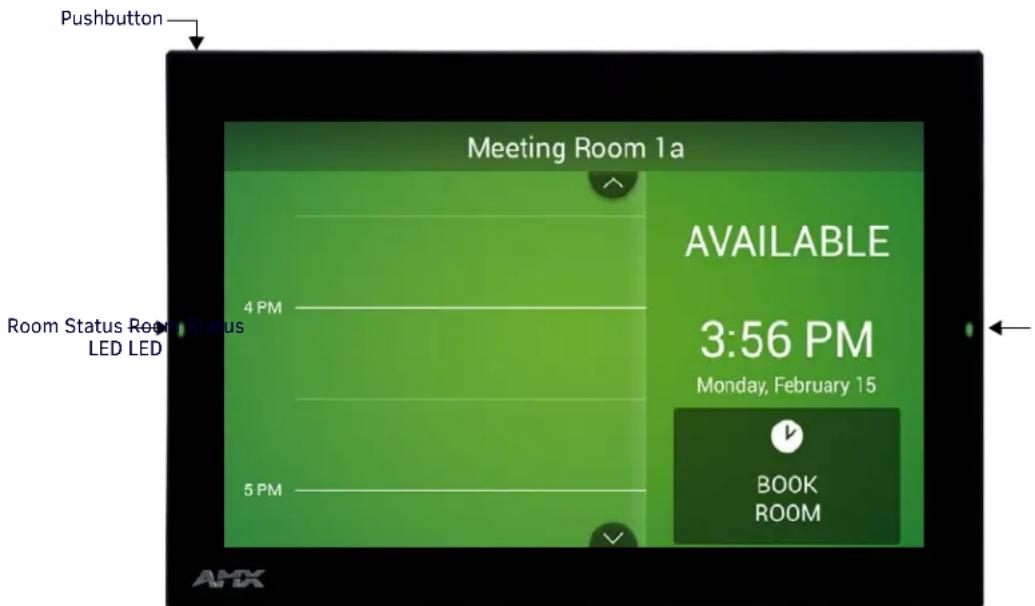
The ACB-2110, 10" Acendo Book Scheduling Panel is shown in FIG. 1:
text_image
Pushbutton Meeting Room 1a 4 PM Room Status Room Status LED LED AVAILABLE 3:56 PM Monday, February 15 5 PM BOOK ROOM AMXFIG. 1 ACB-2110, 10" Acendo Book Scheduling Panel
| ACB-2110 Product Specifications | |
| DIMENSIONS (HWD): 6 13/ | 16" x 10 1/16" x 2" (174 mm x 255 mm x 51 mm) |
| WEIGHT: • 1.95 lbs (.885 Kg), with back box• 1.5 lbs (.680 Kg), without back box | |
| POWER CONSUMPTION: • Full-On: 14.5 W (max)• T y p i c a l : 7 . 5 W• S t a n d b y : 4 . 7 W• Shutdown: 0.8 W | |
| EXTERNAL POWER SUPPLY REQUIRED | Optimal performance requires use of one of the following AMX PoE power supplies (not included):• PS-POE-AF-TC, PoE Injector, 802.3AF Compliant (FG423-83)• NXA-ENET8-2POE, Gigabit PoE Ethernet Switch (FG2178-63) |
| ACB-2110 Product Specifications (Cont.) | |
| TOUCH SCREEN DISPLAY • Display Type: TFT Active Matrix Color LCD with Fringe Field Switching (FFS) - Wide Viewing Angle Technology• Display Size (WH): Landscape: 9.1" x 5.9" (230 mm x 149 mm), 10.8" (274 mm) diagonal• Viewable Area (WH): Landscape: 8.5" x 5.4" (217 mm x 136 mm ), 10.0" (256 mm) diagonal• Resolution: Landscape: 1280x800• Aspect Ratio: Landscape: 16:9• Brightness: 350 cd/m2• Contrast Ratio: 800:1• Color Depth: 16.7M colors• Illumination: LED• Touch Overlay: Resistive | |
| VIEWING ANGLE 85°/85°/85°/85° (Up/Down/Left/Right) | |
| MEMORY • SDRAM: 1 GB | • Flash : 1 6 GB |
| COMMUNICATIONS Ethernet: 10/100 Mbits/s (full duplex) Auto MDI-X, RJ-45 connector. Supported IP and IP-Based Protocols: UCP, TCP, ICMP, DHCP. | |
| FRONT PANEL COMPONENTS | • Room Status LEDs: 2 red/green LEDs on either side of the panel indicate the current room status (green = available, red = occupied). Note that these LEDs can be disabled via options on the Room setup page (see the Setup Wizard: Step 6 - ROOM section on page 31).• Recessed Settings pushbutton (located on the left top edge) provides access to the SETTINGS window. To open the SETTINGS window, use a paper-clip or similar tool to press and hold the pushbutton for 5 seconds. See the Accessing the SETTINGS Window section on page 13 for details. |
| CONNECTIONS • Ethernet: 10/100 port, RJ-45 connector• USB: (1) USB host 2.0, type A port• Power: PoE (Power over Ethernet), 802.3af, class 0 | |
| REGULATORY | • FCC Part 15 Class B• A US / N Z• EN 55032:2012/AC:2013 Class B• CISPR32:2015• Brazil InMetro• I E C / E N - 6 0 9 5 0• KN32 Class B• CAN-ICES-3(B)/NMB-3(B)• U L 6 0 9 5 0 - 1• RoHS/WEEE compliant |
| OPTIONAL ACCESSORIES | • MXSA-REM-TL, Panel Removal Tool (FG5968-99)• MSA-AMK2-10, Any Mount Kit for 10.1" Modero S Series and Acendo Book Touch Panels (FG2265-36)• MSA-MMK2-10, Multi Mount Kit, 10.1" Modero S Series and Acendo Book Touch Panels (FG2265-21)• PS-POE-AF-TC, PoE Injector, 802.3AF Compliant (FG423-83)• NXA-ENET8-2POE, Gigabit PoE Ethernet Switch (FG2178-63)• CB-MSA-10, Rough-In Box and Cover Plate for 10.1" Modero S Series Wall Mount Touch Panel (FG2265-08)• MSA-RMK-10, Rack Mount Kit for 10" Modero S Series Wall Mount Touch Panel (FG2265-14)• MXA-CLK, Modero X/S Series Cleaning Kit (FG5968-16) |
ACB-2107
The ACB-2107, 7" Acendo Book Scheduling Panel is shown in FIG. 2:

text_image
Pushbutton Meeting Room 1a OCCUPIED 3:39 PM Monday, February 15 Ad-Hoc Meeting 4 PM Project meeting 5 PM Room Status LED Room Status LED BOOK ROOMFIG. 2 ACB-2107, 7" Acendo Book Scheduling Panel
| ACB-2107 Product Specifications | |
| DIMENSIONS (HWD): 4 7/8" x 7 3/8" x 2 1/4" (123.9 mm x 187.5 mm x 58 mm) | |
| WEIGHT: • 1.05 lbs (.680 Kg), with back box• 0.8 lbs (.363 Kg), without back box | |
| POWER CONSUMPTION: • Full-On: 11 W (max)• T y p l c a l : 7 . 5 W• S t a n d b y : 4 . 5 W• Shutdown: 0.7 W | |
| EXTERNAL POWER SUPPLY REQUIRED | Optimal performance requires use of one of the following AMX PoE power supplies (not included):• PS-POE-AF-TC, PoE Injector, 802.3AF Compliant (FG423-83)• NXA-ENET8-2POE, Gigabit PoE Ethernet Switch (FG2178-63) |
| TOUCH SCREEN DISPLAY | • Display Type: TFT Active Matrix Color LCD with Fringe Field Switching (FFS) - Wide Viewing Angle Technology• Display Size (WH): Landscape: 7.3" x 4.8" (186 mm x 122 mm), 8.8" (222 mm) diagonal• Viewable Area (WH): Landscape: 6.05" x 3.54" (154 mm x 90 mm), 7.0" (178 mm) diagonal• Resolution: Landscape: 1024x600• Aspect Ratio: Landscape: 16:9• Brightness: 400 cd/m2• Contrast Ratio: 800:1• Color Depth: 16.7M colors• Illumination: LED• T o u c h O v e r l a y : R e s i s t i v e |
| VIEWING ANGLE 89°/89°/89°/89°/89° (Up/Down/Left/Right) | |
| MEMORY • SDRAM: 1 GB | • F l a s h : 1 6 G B |
| COMMUNICATIONS Ethernet: | 10/100 Mbits/s (full duplex) Auto MDI-X, RJ-45 connector. Supported IP and IP-Based Protocols: UCP, TCP, ICMP, DHCP. |
| FRONT PANEL COMPONENTS | • Room Status LEDs: 2 red/green LEDs on either side of the panel indicate the current room status (green = available, red = occupied). Note that these LEDs can be disabled via options on the Room setup page (see the Setup Wizard: Step 6 - ROOM section on page 31).• Recessed Settings pushbutton (located on the left top edge) provides access to the SETTINGS window. To open the SETTINGS window, use a paper-clip or similar tool to press and hold the pushbutton for 5 seconds. See the Accessing the SETTINGS Window section on page 13 for details. |
| CONNECTIONS | • Ethernet: 10/100 port, RJ-45 connector• USB: (1) USB host 2.0, type A port• Power: PoE (Power over Ethernet), 802.3af, class 0 |
ACB-2107 Product Specifications (Cont.)
| REGULATORY • FCC Part 15 Class B• A U S / N Z• EN 55032:2012/AC:2013 Class B• CISPR32:2015• Brazil InMetro• I E C / E N - 6 0 9 5 0• K N 3 2 C l a s s B• C A N - I C E S - 3 ( B ) / N M B - 3 ( B )• U L 6 0 9 5 0 - 1• RoHS/WEEE compliant |
| OPTIONAL ACCESSORIES • MXSA-REM-TL, Panel Removal Tool (FG5968-99)• MSA-AMK2-07 Any Mount Kit for 7" Modero S Series and Acendo Book Touch Panels (FG2265-35)• MSA-MMK2-07, Multi Mount Kit for 7" Modero S Series and Acendo Book Touch Panels (FG2265-22)• PS-POE-AF-TC, PoE Injector, 802.3AF Compliant (FG423-83)• NXA-ENET8-2POE, Gigabit PoE Ethernet Switch (FG2178-63)• CB-MXSA-07, Rough-In Box and Cover Plate for the 7" Wall Mount Modero X/S Series Touch Panels (FG039-18)• MSA-RMK-07,Rack Mount Kit for Modero S Series Touch Panel, 7" (FG2265-15)• MXA-CLK, Modero X/S Series Cleaning Kit (FG5968-16) |
Supported Scheduling Systems
Acendo Book Scheduling Panels support the following scheduling systems: Microsoft Exchange, Office 365 and Google Calendar. The following table indicates the specific versions of each scheduling system that was tested and verified:
Supported Scheduling Systems
| Microsoft Exchange | Exchange 2010 SP3 (Microsoft Exchange Server 2010 Service Pack 3)Exchange 2013 CU11 (Cumulative Update 11 for Exchange Server 2013)Exchange 2016 RTM |
| Office 365 Office 365 Business Premium and Exchange Online (Plan 1) | |
| Google Calendar | Google Apps for Work |
Configuring Acendo Book Touch Panels
Initial Panel Configuration (Scheduling Panel Setup Wizard)
The initial configuration for Acendo Book panels is easily accomplished using the Scheduling Panel Setup Wizard (FIG. 3):
SCHEDULING PANEL SETUP WIZARD
This wizard will help you set up your scheduling panel by configuring the following:

flowchart
graph LR
    A["Overview"] --> B["Network"]
    B --> C["Calendar"]
    C --> D["Localization"]
    D --> E["Group"]
    E --> F["Room"]
    F --> G["Security"]
FIG. 3 Scheduling Panel Setup Wizard
The Scheduling Panel Setup Wizard is automatically launched the first time the Acendo Book panel is powered up. This wizard steps you through the process of configuring network/communications settings for the touch panel, and presents required configuration options for the selected calendar system. See the Using the Scheduling Panel Setup Wizard section on page 22 for details on initial setup and configuration.
Accessing the SETTINGS Window
Scheduler Settings and Advanced Settings are both accessed via the SETTINGS window on the Acendo Book panel.
To invoke the SETTINGS window, use a paper-clip or similar tool to press and hold the recessed Settings pushbutton located on the top edge of the panel (left side - see FIG. 4) for 5 seconds.

text_image
Recessed pushbutton located here Press and hold for 5 seconds to access the SETTINGS window Meeting Room 1a AVAILABLE 3:56 PM Monday, February 15 BOOK ROOM Alternatively, press and hold the Room Name title bar for 5 seconds to access the SETTINGS windowFIG. 4 Pushbutton - Located on the top edge of the panel (left side)
Alternatively, A long press of the room name (5 seconds minimum), will also invoke the SETTINGS window.
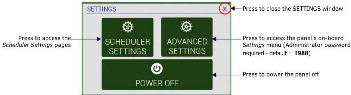
flowchart
graph TD
    A["SCHEDULER SETTINGS"] --> B["POWER OFF"]
    C["ADVANCED SETTINGS"] --> B
    D["Press to access the Scheduler Settings pages"] --> A
    E["Press to close the SETTINGS window"] --> F["X"]
    G["Press to access the panel's on-board Settings menu (Administrator password required - default = 1988)"] --> B
    H["Press to power the panel off"] --> B
FIG. 5 SETTINGS window
Acendo Book touch panels have two sets of configuration options: Scheduler Settings, and Advanced Settings:
NOTE: Scheduler Settings and Advanced Settings are both password-protected. The default Administrator password is "1988". The Administrator password can be changed via options in the Security Setup page - see Changing the Administrator Password on the Panel on page 33 for details.
Configuring Scheduler Settings
While the initial configuration for Acendo Book panels is managed via the Scheduling Panel Setup Wizard (FIG. 3 on page 12), most of the settings made in the Scheduling Panel Setup Wizard can be edited via the Scheduler Settings pages.
Press SCHEDULER SETTINGS in the SETTINGS window to open the Scheduler Settings pages. Refer to the Scheduler Settings section on page 36 for details.
Configuring Touch Panel Settings
ADVANCED SETTINGS are used to configure settings for the touch panel itself. Touch panel-specific settings can be viewed and edited via the ADVANCED SETTINGS option.
Press ADVANCED SETTINGS in the SETTINGS window, and enter the Administrator password to access the panel's on-board Settings menu. Refer to the Advanced Settings section on page 43 for information on viewing/edit touch panel-specific options.
Powering Off the Panel
Note that the SETTINGS window also provides the option to gracefully power down the touch panel.
Press POWER OFF to power down the panel.
Cleaning the Touch Panel
When cleaning the device, do not directly spray the device with cleaning fluid. Instead, spray the cloth and then apply the cloth to the touch screen.
CAUTION: Do NOT use abrasives of any type to clean the device, as abrasives may permanently damage or remove the device's finish.
Installation
Overview
Acendo Book Scheduling (wall mount) Touch Panels can be installed via several mounting options:
- Use the included clear plastic Backbox to attach the panel to most standard wall materials.
- Other optional AMX mounting solutions include the MSA-MMK-xx Multi Mount Kit, the MSA-AMK-xx Any Mount Kit, and the CB-MXSA-xx Rough-In Box. Refer to the Quick Start Guide included with each mounting kit for instructions.
A Note About Wall and Rack Installation
Some products are installed in areas of differing temperature and cooling methodologies. These include products installed in walls, racks, cabinets, etc. Those areas may have different temperatures and/or cooling approaches that must be taken into consideration to maintain the product within the specified operating temperature.
FIG. 6 shows an AMX device installed in a wall with a filled volume (such as with insulation or concrete), as well as with a closed volume (such as between studs in an otherwise finished wall). The diagram shows how heat generated by the device or other devices may have no way to escape, and may build up to levels that may affect device operation.

flowchart
graph TD
    A["T1"] --> B["AMX DEVICE"]
    B --> C["T2"]
    C --> D["FILLED OR CLOSED VOLUME, LIMITED OR NO CONVECTION"]
    style A fill:#f9f,stroke:#333
    style B fill:#ccf,stroke:#333
    style C fill:#cfc,stroke:#333
    style D fill:#fcc,stroke:#333
    note right of D: T1, T2 < T0pMax
    note right of D: T1, T2 > T0pMin
FIG. 6 Heat convection in filled or closed volume, limited or no convection
In FIG. 7, the diagram displays an AMX device in a typical rack mounting, with full air circulation around the front and back of the device. In this case, the main concern is with heat building up between components, possibly to levels that may affect device operation.
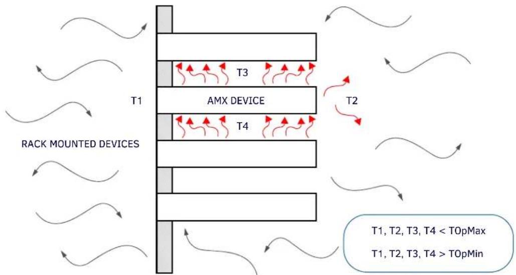
flowchart
graph TD
    A["RACK MOUNTED DEVICES"] --> B["AMX DEVICE"]
    B --> C["T1"]
    B --> D["T2"]
    B --> E["T3"]
    B --> F["T4"]
    style A fill:#f9f,stroke:#333
    style B fill:#ccf,stroke:#333
    style C fill:#cfc,stroke:#333
    style D fill:#fcc,stroke:#333
    style E fill:#cff,stroke:#333
    style F fill:#ffc,stroke:#333
    note right of B: T1, T2, T3, T4 < TOpMax
    note right of F: T1, T2, T3, T4 > TOpMin
FIG. 7 Heat convection in rack-mounted devices
Installation Recommendations
During any installation, a lack of ventilation may produce conditions that may adversely affect the device's operation. In these circumstances, special care must be made to make sure that temperatures within enclosed areas do not exceed the device's maximum rated temperature.
NOTE: While the outside temperature of the device may be at or below its maximum operating temperature, special care must be taken before and during installation to ensure that the maximum operating temperature is not exceeded within wall or rack installation spaces.
Mounting Options
Acendo Book Scheduling Panels can be installed via several mounting options:
Use the included clear plastic Backbox to attach the panel to most standard wall materials.
Other optional AMX mounting solutions include the MSA-MMK2-07/10 Multi Mount Kits, and the MSA-AMK2-07/10 Any Mount Kits, and CB-MXSA-07/10 Rough-In Boxes. Refer to the Quick Start Guide included with each mounting kit for instructions.
Power Over Ethernet
Power for Acendo Book Scheduling Panels is supplied via Power Over Ethernet (PoE), utilizing an AMX-certified PoE injector such as the PS-POE-AF-TC PoE Injector (FG423-83). The incoming Ethernet cable should be connected to the RJ-45 port on the ACB-2110/2107.
Plastic Backbox
Acendo Book Scheduling Panels come with a clear plastic Backbox. This Backbox can be used to mount the touch panel into most standard wall materials. The Backbox can also used to mount the panel into other mounting options.
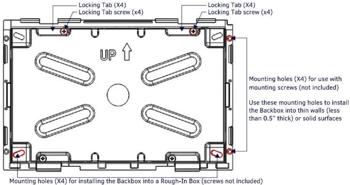
text_image
Locking Tab (X4) Locking Tab screw (x4) UP Mounting holes (X4) for use with mounting screws (not included) Use these mounting holes to install the Backbox into thin walls (less than 0.5" thick) or solid surfaces Mounting holes (X4) for installing the Backbox into a Rough-In Box (screws not included)FIG. 8 ACB-2110 Backbox (Front View)

text_image
Locking Tab (X2) Locking Tab screw (x2) UP ↑ Mounting holes (X4) for use with mounting screws (not included) Use these mounting holes to install the Backbox into thin walls (less than 0.5" thick) or solid surfaces Mounting holes (X2) for installing the Backbox into a Rough-In Box (screws not included)FIG. 9 ACB-2107 Backbox (Front View)
NOTE: For typical mounting surfaces, such as drywall, use the locking tabs as the primary method for securing the Backbox to the surface. For thin walls or solid surfaces, use mounting screws (not included).
STEP 1: Install the Plastic Backbox
Use the included Installation Template to determine the placement of the Backbox in the mounting surface. The outside edges of the template are the same dimensions as the touch panel, which allows you to troubleshoot possible conflicts with wall edges, doors, and other potential obstacles.
NOTE: Prepare the area by removing any screws or nails from the drywall before beginning the cutout process.
- MXD-1001-L - Template, Backbox, 10.1" Touch Panel, Modero S Series (68-2265-03)

text_image
10.57 [268.40] 9.32⁺°¹₋°°₀ [236.65⁺°°₀]⁰ AMX P/M 48-22M5-03 TEMPLATE, BACKBOX, 18.1" MODERO S 5.96⁺°¹₋°°₀ [151.46⁺°°₀]⁰ 7.21 [183.21] FOR REFERENCE ONLY 4X R.13 [3.18]FIG. 10 S Series Installation Templates
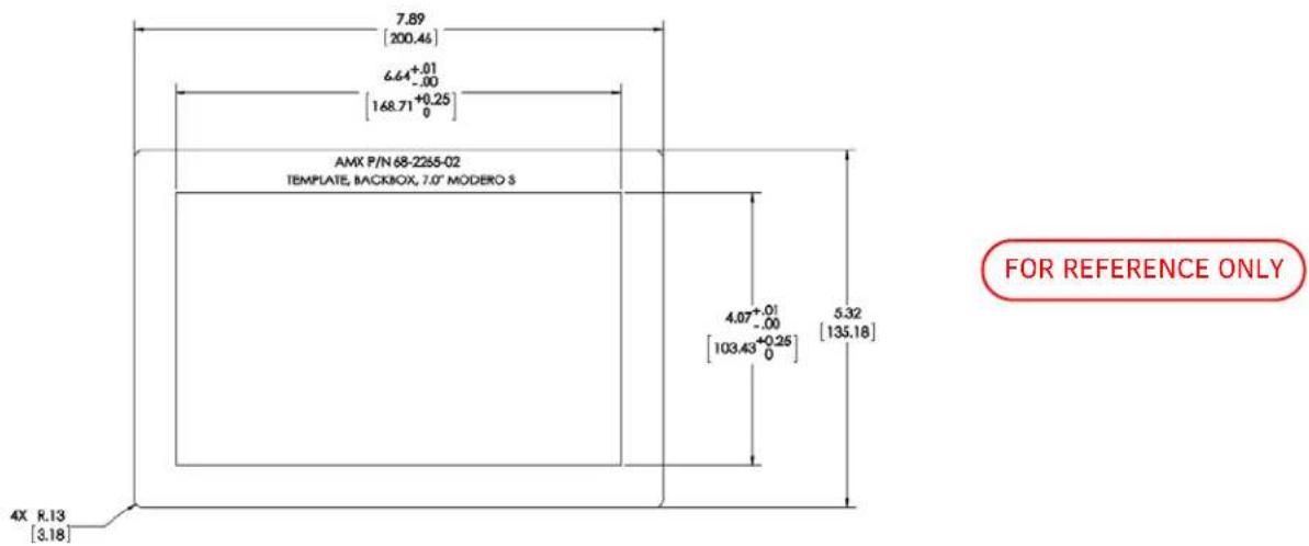
- MXD-701-L - Template, Backbox, 7.0" Touch Panel, Modero S Series (68-2265-02)
text_image
7.89 [200.46] 6.64+0.01 -0.00 [168.71+0.25] 0 AMX P/N 68-2255-02 TEMPLATE, BACKBOX, 7.0" MODERO 3 4.07+0.01 -0.00 [103.43+0.25] 0 5.32 [135.18] FOR REFERENCE ONLY 4X R.13 [3.18]FIG. 11 S Series Installation Templates
The templates are marked to ensure that the touch panel and Backbox are properly aligned.
- After ensuring proper placement, cut an opening in the mounting surface for the Backbox, using the included Installation Template as a guide.
NOTE: When installing the Backbox, make sure that the assembly is in the correct position and in the correct place. Once the locking tabs are extended and locked into place, removing the Backbox may be difficult without having access to the back of the wall or causing damage to the wall.
NOTE: Consider making the actual cutout opening slightly smaller than the provided dimensions. This provides a margin of error if the opening needs to be expanded. Too little wall material removed is always better than too much.
-
Thread the incoming cables (Ethernet and Micro-USB) from their terminal locations through the surface opening, leaving enough slack in the wiring to accommodate any re-positioning of the panel.
-
Remove the Backbox knockouts and thread incoming cables through the knockout holes.
-
Gently push the Backbox into the mounting surface.
- This Backbox uses two Locking Tabs to secure the Backbox to the wall. For typical mounting surfaces, such as drywall, the locking tabs are the primary method for securing the Backbox to the wall.
- To ensure a stable installation, the thickness of the wall material must be a minimum of .50 inches (1.27cm) and a maximum of .875 inches (2.22cm). The mounting surface should also be smooth and flat. For thin walls or solid surfaces, use mounting screws (not included) - see FIG. 8.
- Extend the Locking Tabs by tightening the Locking Tab screws until snug.
- FIG. 12 and FIG. 13 show the Locking Tabs on the ACB-2110 and ACB-2107 Backboxes:

text_image
Locking Tab Locking Tab Locking Tab screws (x4) - tighten to extend each of the four Locking Tabs (max torque = 5 IN-LB) (front) (rear) Locking Tab Locking TabFIG. 12 ACB-2110 Backbox - Locking tab and locking tab screws (X4)

text_image
Locking Tab Locking Tab Locking Tab screws (x4) - tighten to extend each of the four Locking Tabs (max torque = 5 IN-LB) (front)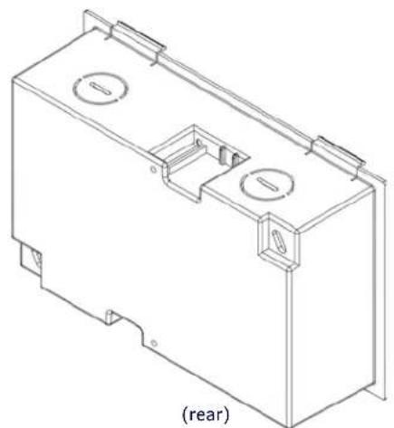
natural_image
Technical line drawing of a rectangular electrical enclosure with two circular cutouts and mounting brackets (no text or symbols)FIG. 13 ACB-2107 Backbox - Locking tab and locking tab screws (X2)
CAUTION: The maximum recommended torque to screw in the locking tabs on the plastic Backbox is 5 IN-LB [56 N-CM]. Excessive torque on the tab screws can strip out the locking tabs or damage the Backbox.
- Extend the Locking Tabs only AFTER the Backbox is inserted into the wall.
- When installing the Backbox, make sure that it is positioned correctly.
- The Backbox is clear to allow visual confirmation that the tabs have been extended and are gripping the wall, as well as in assisting with removal if necessary.
STEP 2: Insert Connectors on the Touch Panel
- Before installing the touch panel into the Backbox, connect the Ethernet and USB cables to the rear of the panel.
- Remove power at the terminal end before continuing with the installation.
NOTE: Do not disconnect the connectors from the touch panel. The panel must be installed with the connectors attached before being inserted into the mounting surface.
STEP 3: Secure the Touch Panel To the Backbox
The Backbox uses notches and tabs on the front edges (top and bottom) to secure the panel into place. Follow the steps below to install the panel into the Backbox, starting the upper edge of the touch panel:
UPPER TABS FIRST
- Center the top edge of the touch panel against the upper outside edge of the Backbox and latch the top of the panel onto the Backbox top-hooks (FIG. 14):

text_image
Use the top-hooks on the top edge of the Backbox to latch the top of the touch panel into place Plastic Backbox ACB-2110 Touch PanelFIG. 14 Engaging the top edge of the panel with the top hooks on the Backbox
- Gently press the top edge of the touch panel into place to engage the panel's notches and the top-hooks on the Backbox.
LOWER TABS - Gently Snap Into Place
- Swing the bottom edge of the touch panel into position until it rests against the lower outside edge of the Backbox.
NOTE: If a gap is observed between the panel and the Backbox, or binding is felt while locking down the panel, stop and verify there are no cables in the way. Do not force the panel into position, or the touch screen or the panel electronics may be damaged.
- Gently press the bottom edge of the panel gently but firmly and ONLY IN THE PLACES INDICATED BELOW until the tabs click into place to secure the panel (FIG. 15):

text_image
Gently press the bottom edge of the touch panel in these places (simultaneously) to snap the bottom edge of the panel into place and secure the panel in the Backbox SEE NOTES BELOW Observe the decal that is placed on the touch panel (glass surface) to avoid pressing the glass in the wrong places, which could result in damage to the panel Plastic Backbox ACB-2110 Touch PanelFIG. 15 SNAPPING THE BOTTOM EDGE OF THE PANEL INTO THE BACKBOX
- Reconnect the terminal Ethernet and USB to their respective locations on either the Ethernet port.
Removing the ACB-2110/701 Panel from the Backbox
The tabs on the bottom edge of the Backbox lock down the ACB-2110 and must be unlatched in order to remove the touch panel from the Backbox. To do this, you'll need a thin probe such as an straightened paper clip, or the (optional) MXSA-REM-TL Bezel Removal Tool:
NOTE: The (optional) MXSA-REM-TL, Bezel Removal Tool (FG5968-99) provides a convenient method to release these clips. The Bezel Removal Tool makes it easy to locate the appropriate release points for each panel size. Refer to the MXSA-REM-TL Quick Start Guide for details.
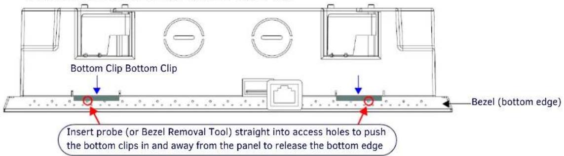
- With a thin probe, carefully press straight into the access holes on the bottom of the bezel (near the center of the bottom tabs) to disconnect the two bottom clips (FIG. 16, FIG. 17).
text_image
Bottom Clip Bottom Clip Insert probe (or Bezel Removal Tool) straight into access holes to push the bottom clips in and away from the panel to release the bottom edge Bezel (bottom edge)FIG. 16 ACB-2110/Backbox assembly

text_image
Bottom Clip Bottom Clip Insert probe (or Bezel Removal Tool) straight into access holes to push the bottom clips in and away from the panel to release the bottom edge Bezel (bottom edge)FIG. 17 ACB-2107/BACKBOX ASSEMBLY - BOTTOM VIEW
- Grasp the bottom of the panel and pull gently outward until the side of the panel is free of the snap. Use your other hand to stabilize the front of the touch panel (FIG. 18):

text_image
Lift the bottom edge of the panel by the plastic bezel and gently rotate up and away from the Backbox Note: To avoid damaging the panel, always pull on the plastic bezel - do not pull on the glass. Note: Hold the panel to prevent it from falling once the bottom edge is freeFIG. 18 ACB-2110/BACKBOX ASSEMBLY (RELEASING THE BOTTOM EDGE OF THE PANEL)
NOTE: Always pull on the frame of the touch panel. NEVER pull on the glass edge.
- With the bottom edge of the panel free, carefully lift up and out to release the tabs on the top edge of the panel.
Installation Dimensions
ACB-2110 Dimensions

Notes:
Dimensions in parenthesis are in millimeters
Additional detailed installation and product drawings are available to view/download at www.amx.com
FIG. 19 ACB-2110
- Detailed specifications drawings for the ACB-2110 are available to download from www.amx.com.
ACB-2107 Dimensions
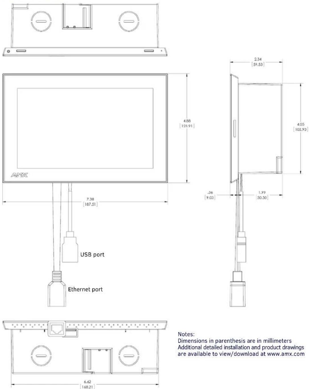
Notes:
Dimensions in parenthesis are in millimeters
Additional detailed installation and product drawings are available to view/download at www.amx.com
- Detailed specifications drawings for the ACB-2107 are available to download from www.amx.com.
FIG. 20 ACB-2107
Using the Scheduling Panel Setup Wizard
Overview
Acendo Book Scheduling Panels are easy to set up using the Scheduling Panel Setup Wizard - a one-time, panel-based configuration wizard to get the panels operational in a matter of minutes with minimal training. The Scheduling Panel Setup Wizard is automatically launched the first time the Acendo Book panel is powered on. This section describes each of the screens presented in the Scheduling Panel Setup Wizard.
NOTE: The Scheduling Panel Setup Wizard will be launched again if "Factory Data Reset" or "Reset Settings" is performed on the panel (via Advanced Settings options; see SYSTEM - Reset and Update on page 61 for details).
- Press the Next button in each Wizard page to save changes and proceed to the next page.
- Note that these settings can be changed later via the Settings pages (see the Scheduler Settings section on page 36 for details).
Setup Wizard: Step 1 - OVERVIEW
The Overview page presents a summary of the steps that entail the Scheduling Panel Setup Wizard (FIG. 21):

text_image
SCHEDULING PANEL SETUP WIZARD This wizard will help you set up your scheduling panel by configuring the following: - Network - Calendar - Localization - Group - Room - Security Overview Network Calendar Localisation Group Room Security NextFIG. 21 Scheduling panel Setup Wizard - Overview page
Review this information and press Next to proceed (to the Network page).
Using the On-Screen Keyboard/Keypad
When each Setup Wizard page opens, the cursor is automatically placed in the first editable text field on the page and the on-screen keyboard or keypad is opened to allow editing of the active field. The example in FIG. 22 shows the NETWORK page with the cursor in the Hostname field (the first and only editable field in this example) and the on-screen keyboard displayed:
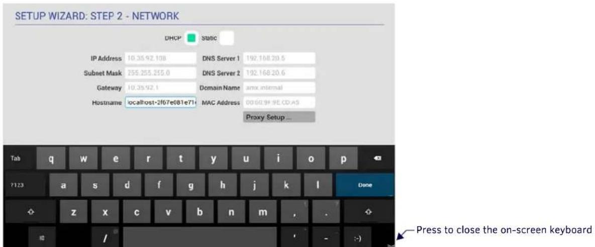
text_image
SETUP WIZARD: STEP 2 - NETWORK DHCP Static IP Address 10.35.92.108 DNS Server 1 192.168.20.5 Subnet Mask 255.255.255.0 DNS Server 2 192.168.20.6 Gateway 10.35.92.1 Domain Name amx internal Hostname localhost-2f67e081e71 MAC Address 0060.9F.9E CD-A5 Proxy Setup ... Tab q w e r t y u i o p ?123 a s d f g h j k l Done z x c v b n m , . Press to close the on-screen keyboardFIG. 22 On-Board Keyboard (Network page)
Note that if the selected field requires numeric entry, the on-screen keypad is opened instead. The example in FIG. 23 shows the cursor in the IP Address field, and the on-screen keypad displayed:
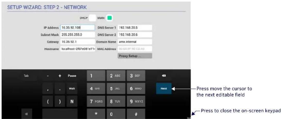
text_image
SETUP WIZARD: STEP 2 - NETWORK DHCP Static IP Address 10.35.92.108 DNS Server 1 192.168.20.5 Subnet Mask 255.255.255.0 DNS Server 2 192.168.20.6 Gateway 10.35.92.1 Domain Name amx internal Hostname localhost-2f07e081e71+ MAC Address 80-603F.NE CD-A3 Proxy Setup ... Tab - + Pause 1 2 ABC 3 DEF , . Wait 4 UHI 5 JKL 6 MNO Next ( ) N 7 PORS 8 TUV 9WXYZ * 0 # Press move the cursor to the next editable field Press to close the on-screen keypadFIG. 23 On-Board Keypad (Network page)
Setup Wizard: Step 2 - NETWORK
Use the options in the NETWORK page to configure the scheduling panel's connection to the network (FIG. 24):
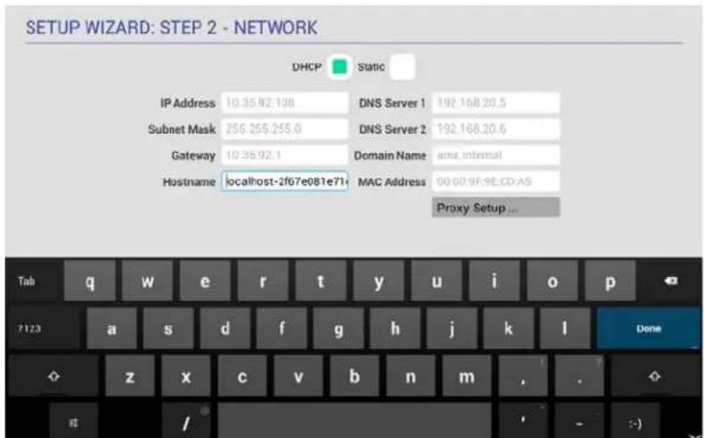
text_image
SETUP WIZARD: STEP 2 - NETWORK DHCP Static IP Address 10.35.92.108 DNS Server 1 192.168.20.5 Subnet Mask 256.255.255.0 DNS Server 2 192.168.20.6 Gateway 10.35.92.1 Domain Name anx internal Hostname localhost-2f67e081e71+ MAC Address 00/00.9F.9E.CD.A$ Proxy Setup ... Tab q w e r t y u i o p 7123 a s d f g h j k l Done z x c v b n m , . / - :)FIG. 24 Setup Wizard: Step 2 - NETWORK
| Setup Wizard - NETWORK page options | |
| DHCP/Static Select how to assign an IP Address to this panel:DHCP (default setting): Select this option to use DHCP to automatically assign an IP address to the panel. Note that when DHCP is selected, the other fields on this page are disabled.Static: Select to manually configure the IP address for this panel using the fields provided on this page. | |
| IP Address Enter a valid IP Address for this panel. | |
| Subnet Mask Enter a valid Subnet Mask address for this panel (as required). | |
| Gateway Enter a valid Gateway address for this panel (as required). | |
| Hostname Enter a valid Hostname for this panel (as required). | |
| DNS Server 1 Enter a valid DNS Server #1 address for this panel (as required). | |
| DNS Server 2 Enter a valid DNS Server #2 address for this panel (as required). | |
| Domain Name Enter a valid Domain Name for this panel (as required). | |
| MAC Address This read-only field provides the MAC Address associated with this panel. | |
| Proxy Setup | Press to configure this scheduling panel to connect to a proxy server (only if necessary), via options in the Proxy Settings page. For Information on Proxy Settings, refer to the Proxy Setup section on page 38. |
Fill in these fields and press Next to proceed (press Back to return to the OVERVIEW page).
NOTE: These settings can be changed later if necessary, via the NETWORK Settings page (see Viewing/Editing Network Settings on page 37).
Setup Wizard: Step 3 - CALENDAR
Use the options in the CALENDAR page to configure the scheduling panel's connection to the scheduling system (FIG. 25):

text_image
SETUP WIZARD: STEP 3 - CALENDAR Microsoft Exchange Office 36s Google Calendar ServerURL Server URL Username Username Password Password Calendar Email ID Calendar Email ID Certificate Validation Strict None Manage Certificates... 1 DyeView Network Calendar Localization Group Room Security Back Verify NextFIG. 25 Setup Wizard: Step 3 - CALENDAR (Microsoft Exchange options shown)
| Setup Wizard - CALENDAR page options | |
| Calender Type Selection | Select the scheduling system that this panel will use:Microsoft Exchange (see page 24)Office 365 (see page 25)Google Calendar (see page 26) |
| Verify | Press to verify that the scheduling panel can connect to the scheduling system using the information currently entered on this page.The system will indicate whether or not is able to connect to the calendar system using the current settings (see FIG. 27 on page 25). If the panel falls to connect, review all information entered on the Calendar page and try again.Note that the Next button remains disabled until the calendar settings have successfully been verified. |
Calendar Types
Use the Calendar Type Selection options at the top of the CALENDAR page to specify the scheduling system that this panel will use. This selection will invoke configuration settings specific to the selected Calendar type, as described below:
Microsoft Exchange
To configure the Acendo Book Panel for use with Microsoft Exchange:
- In the Setup Wizard: Step 3 - Calendar page, select Microsoft Exchange to invoke the following options (FIG. 26):
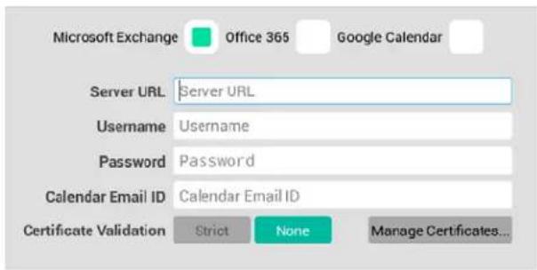
text_image
Microsoft Exchange Office 365 Google Calendar Server URL Server URL Username Username Password Password Calendar Email ID Calendar Email ID Certificate Validation Strict None Manage Certificates...FIG. 26 Microsoft Exchange Calendar Configuration Settings
| Microsoft Exchange Calendar Configuration Settings | |
| Server URL Enter the full URL for the scheduling server. | Example syntax:https:///EWS/Exchange.asmx |
| Username Enter the Username (Including domain) required to login to the scheduling server (as required).Example: "JaneDoe@acme.onmicrosoft.com". | |
| Password Enter the Password required to login to the scheduling server (as required). | |
| Calendar Email ID Enter the Email ID (including domain) used by the scheduling service.Example: "ConfRoom1@acme.onmicrosoft.com" | |
| Certificate Validation | Select Strict to include hostname validation and apply certain certificate requirements - see SSL Validation Schemes (below).Select None to disable validation schemes - see SSL Validation Schemes (below).Select Manage Certificates to open the Security (Advanced Settings) page (see FIG. 100 on page 57), which provides access to Credential Storage options, as described in the Installing Certificates section on page 60. |
- Fill in these fields and press Verify to verify that the scheduling panel can connect to the scheduling system using the information currently entered on this page. The panel will indicate if the connection attempt was successful (FIG. 27):
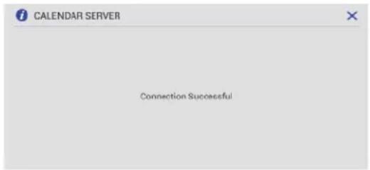
text_image
CALENDAR SERVER Connection Successful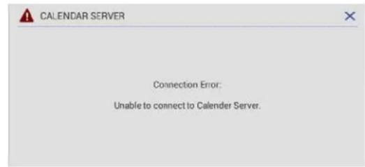
text_image
CALENDAR SERVER Connection Error: Unable to connect to Calender Server.FIG. 27 CALENDAR SERVER (Verify) - Connection Successful/Connection Error
If the panel indicates that the connection attempt was unsuccessful, review all Calendar settings and retry.
- Press Next to proceed (press Back to return to the NETWORK page).
NOTE: For more information, see Appendix B: Configuring Acendo Book Panels for Microsoft Exchange & Office 365 on page 78.
SSL Validation Schemes
| Strict None | |
| Includes hostname validation | no hostname validation |
| do not allow “certificate has expired” | allows “certificate has expired” |
| do not allow “root certificate to be untrusted/self-signed” | allows “root certificate to be untrusted/self-signed” |
| do not allow “certificate signature is invalid” | allows “certificate signature is invalid” |
Off ice 365
To configure the Acendo Book Panel for use with Office 365:
- In the Setup Wizard: Step 3 - Calendar page, select Office 365 (FIG. 28) to invoke the following configuration settings:

text_image
Microsoft Exchange Office 365 Google Calendar Username rmsservice@amxeng.onmicrosoft.com Password ········ Calendar Email ID fullaccess0003@amxeng.onmicrosoft.com Certificate Validation Strict None Manage Certificates...FIG. 28 Office 365 Calendar Configuration Settings
Off ice 365 Calendar Configuration Settings
| Username | Enter the Username (including domain) required to login to the scheduling server (as required).Example: "JaneDoe@acme.onmicrosoft.com". |
| Password | Enter the Password required to login to the scheduling server (as required). |
| Calendar Email ID | Enter the Email ID (including domain) used by the scheduling service.Example: "ConfRoom1@acme.onmicrosoft.com" |
Off ice 365 Calendar Configuration Settings (Cont.)
Certificate Validation
- Select Strict to include hostname validation and apply certain certificate requirements - see SSL Validation Schemes (below).
- Select None to disable validation schemes - see SSL Validation Schemes section on page 25.
-
Select Manage Certificates to open the Security (Advanced Settings) page (see FIG. 100 on page 57), which provides access to Credential Storage options, as described in the Installing Certificates section on page 60.
-
Fill in these fields and press Verify to verify that the scheduling panel can connect to the scheduling system using the information currently entered on this page.
- Press Next to proceed (press Back to return to the NETWORK page).
NOTE: For more information, see Appendix B: Configuring Acendo Book Panels for Microsoft Exchange & Office 365 on page 78.
Google Calendar
To use Google calendar with Acendo Book, a Google Services account must be available. Refer to the Appendix D: Configuring Google Resources on page 82 for details.
To configure the Acendo Book Panel for use with Google calendar:
- In the Setup Wizard: Step 3 - Calendar page, Select Google Calendar (FIG. 29) to invoke the Add option:

text_image
Microsoft Exchange Office 365 Google Calendar (Add an account to proceed) AddFIG. 29 Google Calendar Configuration Settings
- Press Add to invoke the Google sign-in page (FIG. 30):
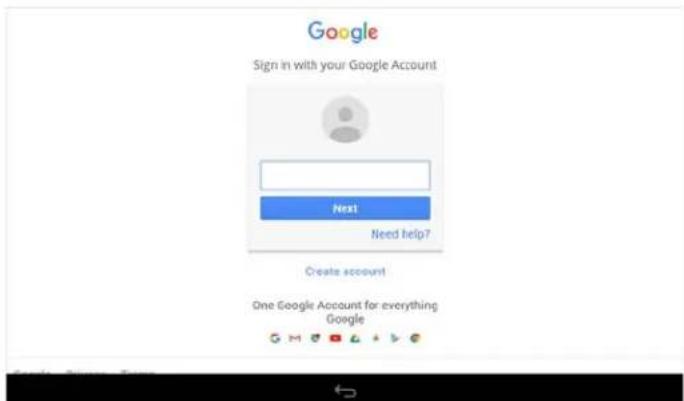
text_image
Google Sign in with your Google Account Next Need help? Create account One Google Account for everything GoogleFIG. 30 Google Sign-In Page
- In the Google Sign-In Page, enter your Google Service account login information and press Next.
- When prompted to allow Acendo Book to manage your calendars, review the terms described, and press Allow to proceed (FIG. 31):

text_image
Google - AMX RoomBook would like to Manage your calendars By clicking Allow you allow this app and Google to use your information in accordance with their respective terms of service and privacy policies. You can change this and other Account Permissions at any time. Deny AllowFIG. 31 Allow Acendo Book to manage Google calendars
- The SELECT CALENDAR window presents a listing of all Acendo Book panel-equipped rooms that are associated with Google calendar. Press to select a Calendar/Room to use as the source of scheduling information for this panel (FIG. 32):
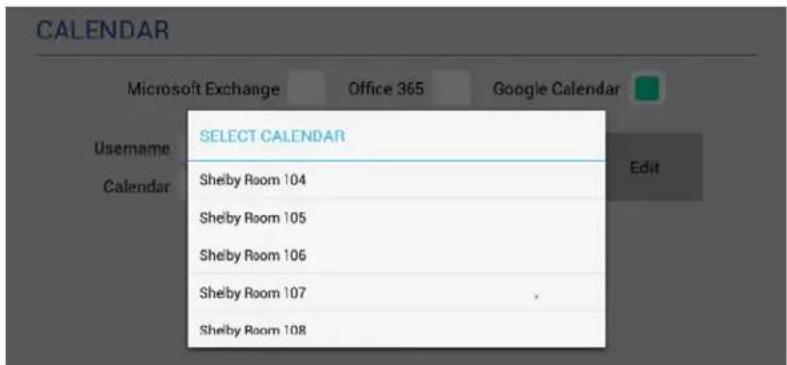
text_image
CALENDAR Microsoft Exchange Office 365 Google Calendar USEMAME SELECT CALENDAR Username Calendar Shelby Room 104 Shelby Room 105 Shelby Room 106 Shelby Room 107 Shelby Room 108 EditFIG. 32 SELECT CALENDAR Window indicating a sample list of Calendars/Rooms
- This selection closes the SELECT CALENDAR window, and displays an updated CALENDAR page, indicating the current Google Username and the Calendar/Room associated with this panel (FIG. 33):
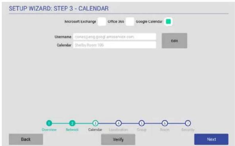
text_image
SETUP WIZARD: STEP 3 - CALENDAR Microsoft Exchange Office 36s Google Calendar Username:\runesjeng.googl.amservice.com Calendar Shelby Room 105 Edit Overview Network Calendar Loxibration Group Next Security Back Verify NextFIG. 33 CALENDAR Page indicating Google Username and selected Calendar
- Fill in these fields and press Verify to verify that the scheduling panel can connect to the scheduling system using the information currently entered on this page.
- Press Next to proceed (press Back to return to the NETWORK page).
NOTE: These settings can be changed later if necessary, via the CALENDAR Settings page (see Viewing/Editing Calendar Settings on page 39).
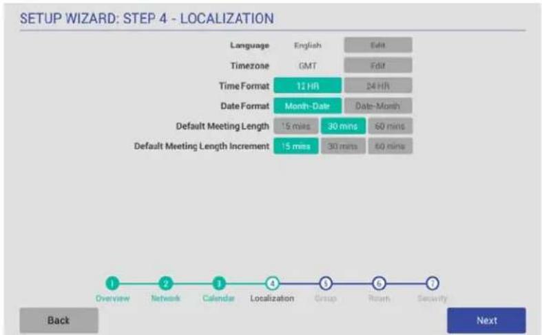
Setup Wizard: Step 4 - LOCALIZATION
Use the options in the LOCALIZATION pages to select a language and time zone to be displayed on this panel (FIG. 34):
flowchart
graph TD
    A["Overview"] --> B["Network"]
    B --> C["Calendar"]
    C --> D["Localization"]
    D --> E["Group"]
    E --> F["Reach"]
    F --> G["Security"]
    style A fill:#f9f,stroke:#333
    style B fill:#f9f,stroke:#333
    style C fill:#f9f,stroke:#333
    style D fill:#f9f,stroke:#333
    style E fill:#f9f,stroke:#333
    style F fill:#f9f,stroke:#333
    style G fill:#f9f,stroke:#333
FIG. 34 Setup Wizard: Step 4 - LOCALIZATION
| Setup Wizard - LOCALIZATION page options | |
| Language | Indicates the current language setting for this panel (default = English). To change languages, press the Language Edit button.This invokes the SELECT LANGUAGE window (see FIG. 35). Press to select a language. |
| Time Zone | Indicates the current time zone setting for this panel (default = GMT). To change the time zone setting, press the Time Zone Edit button.This Invokes the SELECT TIME ZONE window (see FIG. 35). Press to select the appropriate time zone. |
| Time Format | Indicates the current time display setting for this panel (default = 12-hour).To change the time display to 24-hour format, press the 24-hour button. |
| Date Format | Indicates the current date display setting for this panel (default = Month-Date).To change the date display to Month-Date format, press the Month-Date button. |
| Default Meeting Length | This setting specifies how many times each hour this panel can indicate separate meetings. The default setting is 15 minutes, in which case this panel can schedule up to 4 meetings in an hour.To change the default meeting increment setting, press either the 30 mins or 60 mins button.With 30 mins selected, this panel can schedule a meeting every 30 minutes.With 60 mins selected, this panel can schedule a meeting every 60 minutes. |
| Default Meeting Increment | Indicates the current default meeting length setting for this panel (default = 30 minutes).To change the default meeting length setting, press either the 15 mins or 60 mins button. |
| SELECT LANGUAGE | SELECT TIMEZONE |
| Češina | Marshall Islands / GMT-12:00 |
| Deutsch | Midway Island / GMT-11:00 |
| English | Hawaii / GMT-10:00 |
| Español | Alaska / GMT-9:00 |
| Français | Pacific Time / GMT-8:00 |
| Italiano | Tijuana / GMT-8:00 |
| Magyar | Arizona / GMT-7:00 |
| Nederlands | Chihuahua / GMT-7:00 |
| Polski | Mountain Time / GMT-7:00 |
| Português | Central America / GMT-5:00 |
| Ελλήνκά | Central Time / GMT-6:00 |
| Русский | Mexico City / GMT-6:00 |
| العربية | Saskatchewan / GMT-6:00 |
FIG. 35 SELECT LANGUAGE and SELECT TIMEZONE dialogs
Fill in these fields and press Next to proceed (press Back to return to the CALENDAR page).
NOTE: These settings can be changed later if necessary, via the LOCALIZATION Settings page (see Viewing/Editing Localization Settings on page 39).
Setup Wizard: Step 5 - GROUP
Acendo Book touch panels can be configured either as a Master or a Member of a Scheduling Panel Group. Members of a Group communicate with the Master panel, which enables panels to browse the schedules of all Member panels in the same Group. This provides users with the ability to schedule a meeting in any room included in the Scheduling Panel Group, from any panel in the Group. For example, when a room is occupied, users can browse other rooms and schedule a meeting in any of the rooms in the Group.
Use the options in the GROUP page to configure this panel as either the Master, or a Member of a Scheduling Panel Group. Note that there can be only one Master panel for a Group. If there is only one stand-alone Acendo Book panel, then it must be configured as a Master.
NOTE: All Acendo Book scheduling panels in a Group must have firmware version 1.1.x or higher. Scheduling panels running version 1.0.x will not show availability information correctly; a room listed in the Available Rooms page (after pressing Browse Rooms) will be listed as "NOT AVAILABLE".
NOTE: Up to 49 Acendo Book panels can be configured as Members of a Master panel's Group (for a total of 50 panels including the Master). However, note that when configuring Scheduling Groups, smaller Room Groups typically have quicker responsiveness for "Browse Rooms" requests.
Note that when this page is opened, Master is selected by default. Therefore the configuration options presented are specific to configuring this panel as a Master (FIG. 36):

text_image
SETUP WIZARD: STEP 5 - GROUP Master Configuration Master IP/Hostname 10.35.92.108 Username NX Password 1988 Clear Members Clear Overview Network Calendar Localization Group Alarm Security Back NextFIG. 36 Setup Wizard: Step 5 - GROUP page
Press the Info icon next to Master and Member buttons to open the GROUP MASTER/MEMBER window, which provides a summary of how scheduling panels relate to Groups (FIG. 37):
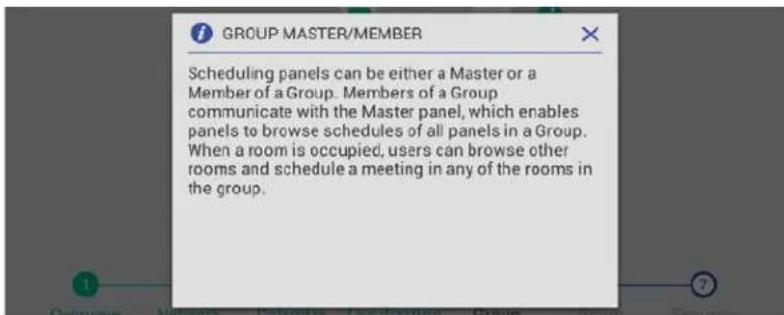
text_image
GROUP MASTER/MEMBER Scheduling panels can be either a Master or a Member of a Group. Members of a Group communicate with the Master panel, which enables panels to browse schedules of all panels in a Group. When a room is occupied, users can browse other rooms and schedule a meeting in any of the rooms in the group.FIG. 37 Group page (GROUP MASTER/MEMBER Information window)
| Setup Wizard - GROUP page options | |
| Master/Member | Specify to use this panel either as a Master panel, or as a member of a Scheduling Panel Group (default = Master). |
| Master Configuration | With Master selected, the following Master Configuration options are presented: |
| Master IP/Hostname | This read-only field displays the Master IP/Hostname currently assigned to this panel. |
| Username Enter a Username to associate with this panel (required for Master panels). | |
| Password Enter a Password to associate with this panel (required for Master panels). | |
Setup Wizard - GROUP page options
| Clear Members | Press to clear any and all members of the Group with which this Master panel is associated. |
| Member Configuration | With Member selected, the following Member Configuration options are presented: |
| Master IP/Hostname | Enter the Master IP/Hostname of the Master panel for the Group to which this Member panel belongs. |
| Username Enter the U | sername associated with the Master panel for this panel's Group. |
| Password Enter the P | Passwords associated with the Master panel for this panel's Group. |
Creating a Scheduling Group
Creating a Group entails configuring one Acendo Book panel to be the Master panel, and configuring other panels to be Member panels:
Configuring the Master Panel
Only one Acendo Book panel can be assigned as the Master panel. If there only one Acendo Book panel, then it must be configured as the Master (see FIG. 36 on page 29).
- In the Setup Wizard: Step 5 - GROUP page, select Master.
- Enter a Username and Password for this panel. These credentials will be required for the Member panels to communicate with the Master panel.
- Press Next to proceed to the ROOM page.
Configuring Member Panels
Once an Acendo Book panel has been configured as the Master panel, up to 49 Acendo Book panels can be configured as Members of the Master panel's Group:
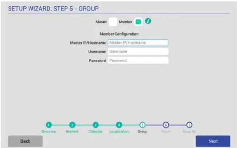
text_image
SETUP WIZARD: STEP 5 - GROUP Master Member Member Configuration Master IP/Hostname: Master IP/Hostname Username: Username Password: Password Overview Network Calendar Localization Group ASM Security- Back NextFIG. 38 Setup Wizard: Step 5 - GROUP page (Member Settings)
- In the Setup Wizard: Step 5 - GROUP page, select Member.
- Enter the IP or Hostname of the Master panel.
- Enter the Username and Password for the Master panel.
- Press Next to proceed to the ROOM page.
Once a Group has been configured, users can browse other Acendo Book panels in the Group for availability, and reserve a meeting on any available panel in the Group. See the Browse Rooms for Scheduling section on page 69 for details.
NOTE: These settings can be changed later if necessary, via the GROUP Settings page (see Viewing/Editing Group Settings on page 41).
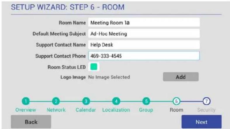
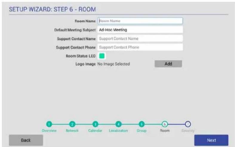
Setup Wizard: Step 6 - ROOM
Use the options in the ROOM pages to set room-level options for this panel (FIG. 39):
text_image
SETUP WIZARD: STEP 6 - ROOM Room Name Meeting Room 1a Default Meeting Subject Ad-Hoc Meeting Support Contact Name Help Desk Support Contact Phone 469-333-4545 Room Status LED Logo Image No Image Selected Add Overview Network Calendar Localization Group Room Security Back NextFIG. 39 Setup Wizard: Step 6 - ROOM page
| Setup Wizard - ROOM page options | |
| Room Name Enter the room name as it will appear on this panel. | |
| Default Meeting Subject | Enter a default meeting subject to be displayed on this panel.Note that this default subject can be over-written in the Room page (see the Editing Meeting Details section on page 71). |
| Support Contact Name | Enter the name of the support personnel as it will appear on this panel. |
| Support Contact Phone | Enter the phone number of the support personnel as it will appear on this panel. |
| Room Status LED | Press to toggle the Room Status LEDs on the panel, which light green when the Room is available, or red when the Room is occupied (default = enabled). |
| Logo Image | Indicates the current logo image, if applicable. Press Add to add a custom logo image.Supported Formats: JPG, PNGThe custom logo image window is 375 x 165. Acendo Book Panels will take the downloaded image and scale it down to fit in the window. However, to maximize the available space, the downloaded logo should have a similar aspect ratio (~2.2). |
Fill in these fields and press Next to proceed (press Back to return to the GROUP page).
NOTE: These settings can be changed later if necessary, via the ROOM Settings page (see Viewing/Editing Room Settings on page 42).
Changing the Logo Image
The Main Room page on each scheduling panel includes a graphic window for a logo. The logo image can be changed via the Logo Image option in the Room page:
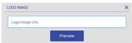
- In the Setup Wizard: Step 6 - ROOM page, select Add.
- In the LOGO IMAGE WINDOW, enter a URL to an image file and press Upload to upload the selected file to the panel. The LOGO IMAGE PREVIEW window provides a preview of the selected image (FIG. 40):
text_image
LOGO IMAGE Logo Image URL PreviewFIG. 40 Setup Wizard: Step 6 - Room page (LOGO IMAGE PREVIEW window showing an example logo image)
NOTE: The custom logo image window is 375 x 165 (pixels). Acendo Book Panels will automatically scale the uploaded image down to fit in the window. For best results the downloaded logo should be at least 375 x 165 pixels and have a similar aspect ratio (\~2.2).
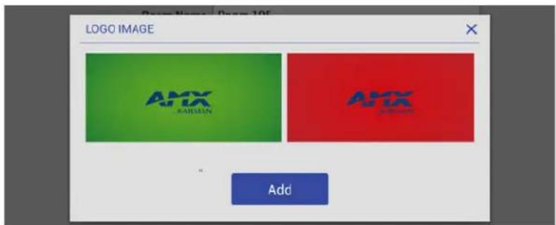
Press Preview to preview the specified image. The LOGO IMAGE window provides a preview of the selected logo, as it will appear on both the Available (green) and Occupied (red) backgrounds (FIG. 41):
text_image
LOGO IMAGE AMX KARISSEN AMX AddFIG. 41 Setup Wizard: Step 6 - Room page (LOGO IMAGE PREVIEW window showing an example logo image)
3. Press Add to upload the specified image.
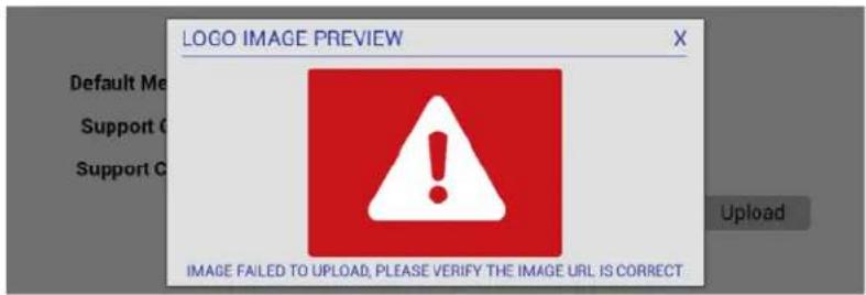
Note that if the image file fails to load, the panel will prompt you to verify that the image URL is correct (FIG. 42):
text_image
LOGO IMAGE PREVIEW Default Me Support C Support C IMAGE FAILED TO UPLOAD, PLEASE VERIFY THE IMAGE URL IS CORRECT UploadFIG. 42 Setup Wizard: Step 6 - Room page (LOGO IMAGE PREVIEW window showing an example logo image)
In this case, verify the URL and try again.
When an image is successfully uploaded, it is displayed next to Logo Image (FIG. 44):
text_image
SETUP WIZARD: STEP 6 - ROOM Room Name Room Name Default Meeting Subject Ad-Hoc Meeting Support Contact Name Support Contact Name Support Contact Phone Support Contact Phone Room Status LED Logo Image No Image Selected Add 1 Overview 2 Network 3 Calendar 4 Localization 5 Group 6 Room 7 Security Back NextFIG. 43 Setup Wizard: Step 7 - ROOM page (indicating an uploaded Logo Image)
Once a logo image has been uploaded, a Delete button is provided on this page. Press Delete to delete the current custom logo image.
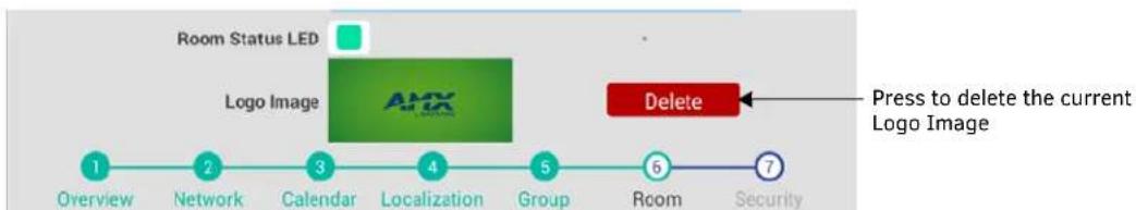
flowchart
graph LR
    A["Overview"] --> B["Network"]
    B --> C["Calendar"]
    C --> D["Localization"]
    D --> E["Group"]
    E --> F["Room"]
    F --> G["Security"]
    H["Room Status LED"] --> I["Logo Image"]
    J["Delete"] --> K["Press to delete the current Logo Image"]
FIG. 44 Setup Wizard: Step 7 - ROOM page (Indicating an uploaded Logo Image)
Setup Wizard: Step 7 - SECURITY
Use the options in the SECURITY page to configure the security settings for this panel (FIG 45):

text_image
SETUP WIZARD: STEP 7 - SECURITY Administrator Password 1988 Require Meeting PIN Code Read Only Mode Privacy Mode Private Meeting Subject Private Meeting Overview Network Calendar Localization Group Room Security Back Finish Press to close the Scheduling Panel Setup WizardFIG. 45 Setup Wizard: Step 7 - SECURITY page
| Setup Wizard - SECURITY page options | |
| Administrator Password | Press to change the Administrator password that is required to access Scheduler Settings, and Advanced (touch panel) Settings on this panel (default = 1988). |
| Require Meeting PIN Code | When enabled, the PIN code will be required to reserve a meeting, edit Meeting Time/Details and Delete Meeting. Press to enable this option (default = disabled). |
| Meeting PIN Code | Enter the 4-digit PIN code that will be required to reserve, edit or delete a meeting on this panel, only if the Require Meeting PIN Code option (above) is enabled. |
| Read Only Mode | Press to toggle this option (default = disabled).When enabled, all fields on the Room page are displayed, but are read-only. In this case, users will be able to see all meetings and reservation details, but will not be allowed to reserve, edit or delete meetings on this panel. |
| Privacy Mode | Press to toggle this option (default = disabled).When in Privacy Mode, information considered to be private is hidden and immutable on this panel. See the Privacy Mode section on page 34 for details.Note: If a meeting is booked outside of an Acendo Book panel (i.e directly via the scheduling system software), then the subject line of the meeting will be replaced with the Private Meeting Subject text (default = "Private Meeting"). The default Private Meeting Subject text can be edited if desired (see page 34). |
| Private Meeting Subject | Press to enter the text that will be used as the meeting subject displayed for private meetings. The text entered here provides the meeting subject for all types of private meetings:It will be used when Privacy Mode is enabled on the Acendo Book panel.Will be used when a meeting is marked as Private by the calendar server (Exchange/Office 365/Google). |
| Finish | Press to exit the Setup Wizard (see Exiting the Scheduling Panel Setup Wizard on page 35). |
Changing the Administrator Password on the Panel
The Administrator password is required to access the Acendo Book panel's SCHEDULER SETTINGS and ADVANCED SETTINGS pages. The default Administrator password is 1988. It is recommended to change this password:
- Press the Administrator Password text field in the SECURITY page to invoke an on-screen keyboard.
- Enter the new password and press Done.
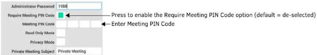
Setting a Meeting PIN Code
The Meeting PIN Code is a 4-digit PIN code that will be required in order to reserve a meeting, edit meeting details or delete a meeting on this panel, only if the Require Meeting PIN Code option is enabled (FIG. 46):
text_image
Administrator Password 1988 Require Meeting PIN Code Meeting PIN Code Read Only Mode Privacy Mode Private Meeting Subject Private Meeting Press to enable the Require Meeting PIN Code option (default = de-selected) Enter Meeting PIN CodeFIG. 46 Security page - Require Meeting PIN Code selected and Meeting PIN Code entry field enabled
To set a Meeting PIN Co de:
- Press the Meeting PIN Code field in the SECURITY page to invoke an on-screen keypad.
- Enter the new 4-digit PIN.
- The keypad automatically closes when 4 digits are entered.
Privacy Mode
When the Acendo Book panel is in Privacy Mode, information considered to be private is hidden (and immutable) on the Acendo Book panel's interface.
Privacy Mode: Meetings Scheduled from an Acendo Book Panel
- When a booking is made, the user cannot define meeting details (subject, message body).
- After reservation is made, meeting is displayed on the Acendo Book Panel with Default Meeting Subject (defined in Room Settings Page).
- If the meeting is selected, no organizer or details are shown and the user is unable to edit the meeting details.
Privacy Mode: Meetings Scheduled from Mail/Web Client
If a meeting is booked directly via the scheduling system software, then the subject line of the meeting will be replaced with the Private Meeting Subject text (default = "Private Meeting").
- Meeting subject is replaced with the Default Private Meeting Subject text, as defined in the SECURITY page (see Editing the Private Meeting Subject Message Text below).
- If the meeting is selected, no organizer or details are shown.
NOTE: Acendo Book panels use Exchange, Office 365 or Google "privacy" flag. A meeting marked as private will behave the same way the global Acendo Book "Privacy Mode" behaves. In order for the Acendo Book panel to be able to read the privacy mode flag in Exchange and Office 365, the Exchange server must set the room's "-RemovePrivateProperty" to \false. By default, this is set to \true.
Editing the Private Meeting Subject Message Text
- Press inside the Privacy Mode field to edit the Private Meeting Subject message text.
- Press Done to save changes and close the on-screen keyboard.
NOTE: These settings can be changed later if necessary, via the SECURITY Settings page (see Viewing/Editing Security Settings on page 42).
Exiting the Scheduling Panel Setup Wizard
Press the Finish button on the Setup Wizard: Step 7 - Security page to close the Scheduling Panel Setup Wizard (FIG. 47):

flowchart
graph LR
    A["Overview"] --> B["Network"]
    B --> C["Calendar"]
    C --> D["Localization"]
    D --> E["Group"]
    E --> F["Floor"]
    F --> G["Security"]
    G --> H["Finish"]
    style H fill:#0066cc,stroke:#333
    note right of H Press to close the Scheduling Panel Setup Wizard
    Back
FIG. 47 Setup Wizard: Step 7 - SECURITY page
When the SETUP WIZARD is closed, the Room page for this panel is displayed (FIG 48):
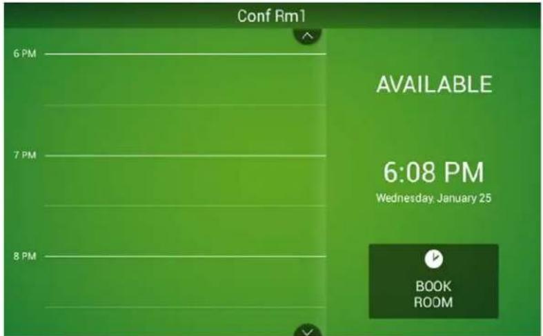
text_image
Conf Rm1 6 PM 7 PM 8 PM AVAILABLE 6:08 PM Wednesday, January 25 BOOK ROOMFIG. 48 Example Room Available page (Meeting room)
- Note that the settings made in the Scheduling Panel Setup Wizard can be changed via the Scheduler Settings pages. Refer to the Scheduler Settings section on page 36 for details.
- For information on using Acendo Book panels to schedule meetings, refer to the Acendo Book Scheduling Panels - User Guide section on page 66.
Scheduler Settings
Overview
Most of the settings made in the Scheduling Panel Setup Wizard (see page 22) can be viewed and edited via the Scheduler Settings options, as described below.
NOTE: Refer to the Advanced Settings section on page 43 for information on viewing/edit touch panel-specific options.
Accessing the Scheduler Settings Pages
- Press and hold the pushbutton on the top of the touch panel for 5 seconds to invoke the SETTINGS window (FIG. 49):

flowchart
graph TD
    A["SCHEDULER SETTINGS"] --> B["ADVANCED SETTINGS"]
    style A fill:#99ccff,stroke:#333
    style B fill:#99ccff,stroke:#333
FIG. 49 SETTINGS window - SCHEDULER SETTINGS
NOTE: Alternatively, press and hold the room name for approximately 5 seconds to open the Settings window.
- Press SCHEDULER SETTINGS. These settings are password-protected. Enter the Administrator password for the scheduling system in the ENTER PASSWORD field (FIG. 50):

text_image
Meeting Room 1a ENTER PASSWORD Cancel Administrator Password Submit q w e r t y u i o p a s d f g h j k l Done z x c v b n m ?123 /FIG. 50 Administrator Login window
• The default password is 1988.
- This password is configured in the Security page of the Setup Wizard - see Setup Wizard: Step 7 - SECURITY on page 33.
- Press Submit. If the password entered was valid, the SETTINGS pages are opened (FIG. 51):
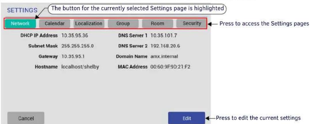
text_image
SETTINGS The button for the currently selected Settings page is highlighted Network Calendar Localization Group Room Security Press to access the Settings pages DHCP IP Address 10.35.95.36 DNS Server 1 10.35.101.7 Subnet Mask 255.255.255.0 DNS Server 2 192.168.20.6 Gateway 10.35.95.1 Domain Name amx.internal Hostname localhost/shelby MAC Address 00:60:9F:9D:21:F2 Cancel Edit Press to edit the current settingsFIG. 51 SETTINGS Pages (Network Settings page shown)
The SETTINGS pages provide the ability to view/edit the Scheduler Settings on this panel. Note that these pages are presented in a similar fashion to the pages in the Scheduling Panel Setup Wizard - the initial Settings page presented is the Network Settings page (shown in FIG. 51).
- Press any of the buttons along the top of the page to access each Settings page.
Viewing/Editing Network Settings
- Press Network to view the current Network settings for this panel (FIG. 52):
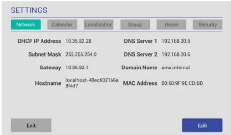
text_image
SETTINGS Network Calendar Localization Group Room Security DHCP IP Address 10.35.82.28 DNS Server 1 192.168.20.5 Subnet Mask 255.255.254.0 DNS Server 2 192.168.20.6 Gateway 10.35.82.1 Domain Name amx.internal Hostname localhost-48ec602166a 8f4d7 MAC Address 00:60:9F:9E:CD:BD Exit EditFIG. 52 SETTINGS Page - Network
- Press Edit to open the NETWORK Settings page, to edit the current settings as required (FIG. 53).

text_image
NETWORK DHCP Static IP Address 10.35.92.108 DNS Server 1 192.168.20.5 Subnet Mask 255.255.255.0 DNS Server 2 192.168.20.6 Gateway 10.35.92.1 Domain Name amx internal Hostname chrismbk3 MAC Address 00 60 9F SE CD A5 Proxy Setup ... Press to open the Proxy Settings page Tab q w e r t y u i o p ?123 a s d f g h j k l Done z x c v b n m , .FIG. 53 NETWORK Settings page
- Press on any enabled field and use the on-screen keyboard or keypad to edit these fields as necessary.
- Press Next to jump to the next editable field on this page. The fields on the NETWORK Settings page are described on page 23. NOTE: The example in FIG 53 shows all fields enabled. This is because with "Static" selected, all network information must be manually entered. When DHCP is selected, only the "Hostname" field is enabled for editing.
- Press Proxy Setup to enable/disable the Proxy option and configure Proxy Settings and Account Information as required, in the Proxy Settings page. By default Proxy is disabled on RMBK panels, Refer to the Proxy Setup section on page 38 for details.
- Press Save to save changes and close the NETWORK Settings page.
NOTE: The panel's Network settings can be also be edited via Advanced Settings (see CONNECTIONS - Ethernet on page 50).
Changing the IP Address on the Acendo Book Panel
Select either DHCP or Static at the top of the NETWORK Settings page.
- Note that by default, DHCP is selected (and the remaining addressing options on this page are disabled).
- If Static is selected, the fields on this page are enabled and must be filled in manually.
Proxy Setup
Press the Proxy Setup button on the NETWORK Settings page (see FIG. 53 on page 37) to access the Proxy Settings page (FIG. 54):
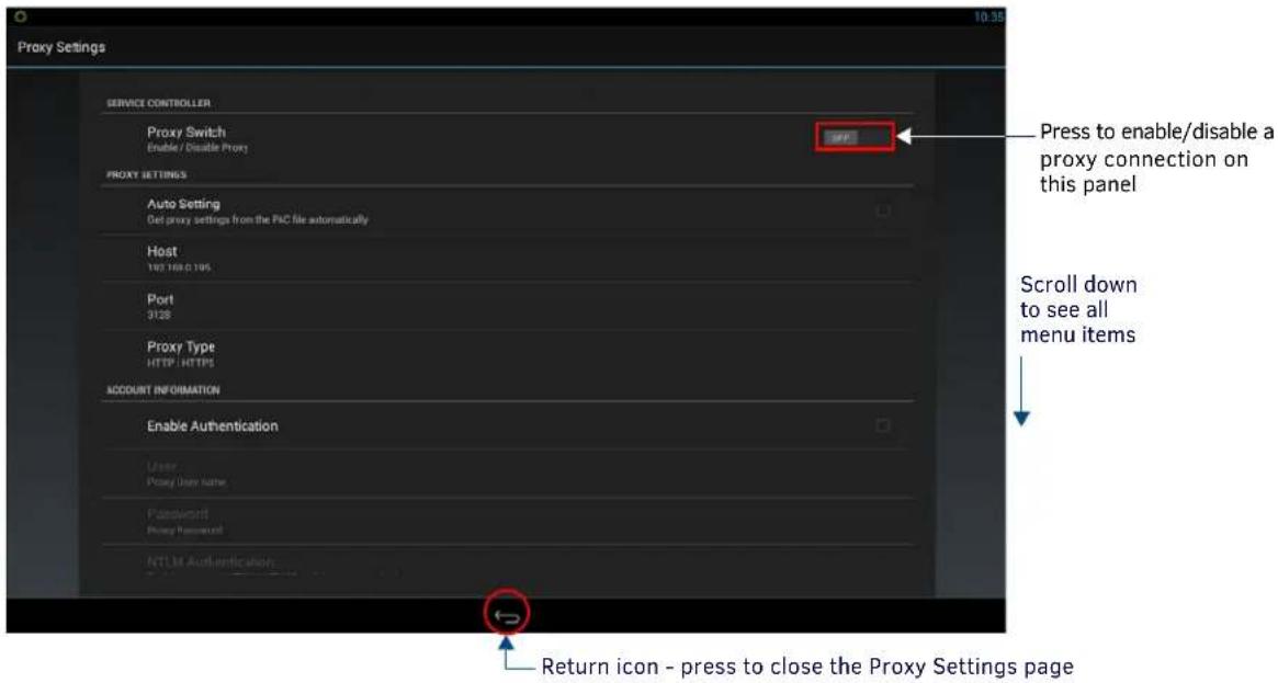
text_image
Proxy Settings SERVICE CONTROLLER Proxy Switch Enable / Disable Proxy Proxy SETTINGS Auto Setting Get proxy settings from the PAC file automatically Host 142.108.1195 Port 3128 Proxy Type HTTP: HTTPS ACCOUNT INFORMATION Enable Authentication User Proxy Item Name Password Proxy Password NTLM Authentication Press to enable/disable a proxy connection on this panel Scroll down to see all menu items Return icon - press to close the Proxy Settings pageFIG. 54 Proxy Settings page
Use the options in the Proxy Settings page to enable/disable the Proxy option and configure Proxy Settings and Account Information as required.
NOTE: By default Proxy is disabled on RMBK panels.
| Proxy Settings page options | |
| SERVICE CONTROLLER | |
| Proxy Switch | Push this button to enable or disable Proxy support on this panel. Note that by default, the Proxy Switch is set to "OFF", indicating that proxy support is disabled. If this panel will connect to a proxy server, press this button to toggle the Proxy Switch to "ON" (enabled).Note that when the Proxy Switch is set to ON, the proxy configuration options on this page are disabled. These options can only be set when the Proxy Switch is set to OFF. |
| PROXY SETTINGS | |
| Auto Setting | When enabled, this panel will automatically retrieve the proxy settings from a PAC (proxy auto-config) file on the proxy server. To use this option, a valid PAC file must reside on the proxy server.Press this option to enable using a PAC file for proxy settings. A blue checkmark in the Auto Setting option indicates that this option is enabled. Note that when this option is enabled, the remaining PROXY SETTINGS on this page are disabled, since manual entry is not needed. |
| Host Press to manually enter the Host (IP Address) of the proxy server. | |
| Port Press to manually enter the Port number on the proxy server that will be used for this RMBK panel. | |
| Proxy Type Press to select the Proxy Type used on the proxy server to which this RMBK panel will connect.The options are HTTP/HTTPS (the default setting), SOCKS4 and SOCKS5. | |
| ACCOUNT INFORMATION | |
| Enable Authentication | If this panel will connect to a secured proxy server (one that requires a Proxy Username and Proxy Password in order to connect), press this option to enable the User and Password options described below. Note that by default, the Enable Authentication option is set to "OFF".A blue checkmark in the Enable Authentication option indicates that this option is enabled. Note that when this option is enabled, the remaining ACCOUNT INFORMATION options on this page are enabled. |
| User | If the Enable Authentication option is selected, press this option to enter the Proxy User name required by the server. |
| Password | If the Enable Authentication option is selected, press this option to enter the Proxy Password required by the server. |
| NTLM Authentication | If this panel will connect to a NTLM/NTLM2 secured proxy server (one that uses NT LAN Manager authentication methods), press this option to enable the Domain option described below. Note that by default, the NTLM Authentication option is set to "OFF". |
| Domain | If the NTLM Authentication option is selected, press to enter the Domain name required for proxy server. |
Viewing/Editing Calendar Settings
- In any SETTINGS page, press Calendar to view the current Calendar settings for this panel (FIG. 55):
Network
Calendar
Localization
Group
Room
Security
FIG. 55 SETTINGS Page - Calendar
- Press Edit to open the CALENDAR Settings page, to edit the current settings as required (FIG. 56).
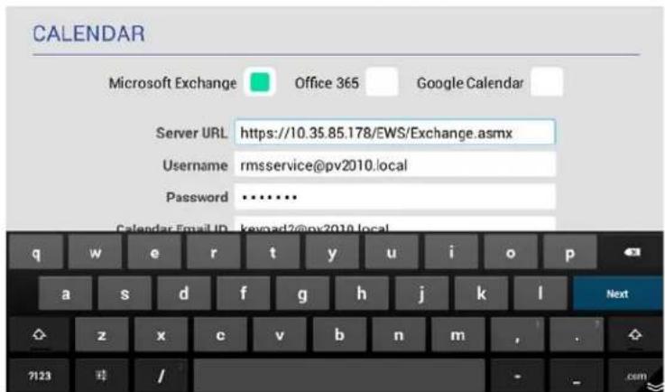
text_image
CALENDAR Microsoft Exchange Office 365 Google Calendar Server URL https://10.35.85.178/EWS/Exchange.asmx Username rmsservice@pv2010.local Password .......... Calendar Email ID keyword2@pv2010.local q w e r t y u i o p a s d f g h j k l Next z x c v b n m , . ? ? ?123 / - osmFIG. 56 CALENDAR Settings page
- Press on any enabled field and use the on-screen keyboard or keypad to edit these fields as necessary. Press Next to jump to the next editable field on this page. The fields on the CALENDAR Settings page are described on page 24.
- Press Save to save changes and close the CALENDAR Settings page.
More Information
• See Appendix B: Configuring Acendo Book Panels for Microsoft Exchange & Office 365 on page 78.
• See Appendix D: Configuring Google Resources on page 82.
• See Appendix A: Troubleshooting on page 73.
Viewing/Editing Localization Settings
- In any SETTINGS page, press Localization to view the current Localization settings for this panel (FIG. 57):
Network
Calendar
Localization
Group
Room
Security
FIG. 57 SETTINGS Page - Localization
- Press Edit to open the LOCALIZATION Settings page, to edit the current settings as required (FIG 58).
LOCALIZATION

other
| Category | Timeframe | English | Edit | CST | Duration (min) | | :--- | :--- | :--- | :--- | :--- | :--- | | Timeframe | Time Format | 12 HR | 24 HR | | | | Date Format | Date Format | Month-Date | Date-Month | | | | Default Meeting Length | Default Meeting Length Increment | 15 mins | 30 mins | 50 mins | | | Default Meeting Length Increment | Default Meeting Length Increment | 15 mins | 30 mins | 50 mins | |FIG. 58 LOCALIZATION Settings page
- Press Save to save changes and close the LOCALIZATION Settings page. The fields on the LOCALIZATION Settings page are described on page 28.
NOTE: The panel's Localization settings can be also be edited via Advanced Settings (see SYSTEM - Date & Time on page 52 and SYSTEM - Language & Input on page 53).
Changing the Language Displayed On the Acendo Book Panel
- Open the SCHEDULER SETTINGS - Localization Page.
- Press Edit to access the LOCALIZATION Settings page.
- Press the Edit button next to Language to access a listing of all languages that can be displayed on this Acendo Book Panel, in the SELECT LANGUAGE window (FIG. 59):
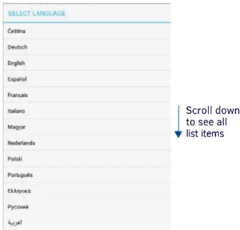
text_image
SELECT LANGUAGE Čeština Deutsch English Español Français Italiano Magyar Nederlands Polski Português Екляпукá Русский ЗвіліяFIG. 59 SELECT LANGUAGE window
NOTE: Press anywhere outside the SELECT LANGUAGE window to close the window without making a selection.
- Press Save in the LOCALIZATION Settings page to save this change.
Changing the Timezone Displayed On the Acendo Book Panel
- Open the SCHEDULER SETTINGS - Localization Page.
- Press Edit to access the LOCALIZATION Settings page.
- Press the Edit button next to Timezone to access a listing of all time zones that can be displayed on this Acendo Book Panel, in the SELECT TIMEZONE window (FIG. 60):
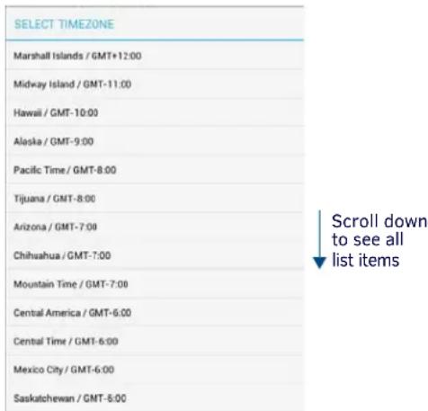
text_image
SELECT TIMEZONE Marshall Islands / GMT+12:00 Midway Island / GMT-11:00 Hawaii / GMT-10:00 Alaska / GMT-9:00 Pacific Time / GMT-8:00 Tijuana / GMT-8:00 Arizona / GMT-7:00 Chihuahua / GMT-7:00 Mountain Time / GMT-7:00 Central America / GMT-6:00 Central Time / GMT-6:00 Mexico City / GMT-6:00 Saskatchewan / GMT-5:00 Scroll down to see all list itemsFIG. 60 SELECT TIMEZONE window
NOTE: Press anywhere outside the SELECT TIMEZONE window to close the window without making a selection.
- Press Save in the LOCALIZATION Settings page to save this change.
Changing the Time Format Displayed On the Acendo Book Panel
- Open the SCHEDULER SETTINGS - Localization Page.
- Press Edit to access the LOCALIZATION Settings page.
- Next to Time Format, press to select either 12HR (default setting) or 24 HR time format.
- Press Save in the LOCALIZATION Settings page to save this change.
Changing the Date Format Displayed On the Acendo Book Panel
- Open the SCHEDULER SETTINGS - Localization Page.
- Press Edit to access the LOCALIZATION Settings page.
-
Next to Date Format, press to select either Month-Date (default setting) or DATE-MONTH date format.
-
Press Save in the LOCALIZATION Settings page to save this change.
Changing the Default Meeting Length Displayed On the Acendo Book Panel
- Open the SCHEDULER SETTINGS - Localization Page.
- Press Edit to access the LOCALIZATION Settings page.
- Next to Default Meeting Length, press to select 15 mins, 30 mins (default setting) or 60 mins.
- Press Save in the LOCALIZATION Settings page to save this change.
Changing the Default Meeting Length Increment Displayed On the Acendo Book Panel
- Open the SCHEDULER SETTINGS - Localization Page.
- Press Edit to access the LOCALIZATION Settings page.
- Next to Default Meeting Length Increment, press to select 15 mins (default setting), 30 mins or 60 mins.
- Press Save in the LOCALIZATION Settings page to save this change.
Viewing/Editing Group Settings
- In any SETTINGS page, press Group to view the current Group settings for this panel (FIG. 61):
Network
Calendar
Localization
Group
Room
Security
FIG. 61 SETTINGS Page - Group
- Press Edit to open the GROUP Settings page, to edit the current settings as required (FIG. 62).

text_image
GROUP Master Member i Master Configuration Master IP/Hostname 10.35.82.86 Username johndoe Password 1234 q w e r t y u i o p a s d f g h j k l Next z x c v b n m , .FIG. 62 GROUP Settings page
- Press on any enabled field and use the on-screen keyboard or keypad to edit these fields as necessary. Press Next to jump to the next editable field on this page. The fields on the GROUP Settings page are described on page 29.
- Press Save to save changes and close the GROUP Settings page.
Viewing/Editing Room Settings
- In any SETTINGS page, press Room to view the current Room settings for this panel (FIG. 61):
Network
Calendar
Localization
Group
Room
Security
FIG. 63 SETTINGS Page - Room
- Press Edit to open the ROOM Settings page, to edit the current settings as required (FIG. 62).

text_image
ROOM Room Name Keypad 2 Default Meeting Subject Ad-Hoc Meeting Support Contact Name Jackie Joe Support Contact Phone 469.555.7654 Room Status LED q w e r t y u i o p a s d f g h j k l Next z x c v b n m , . ?FIG. 64 ROOM Settings page
- Press on any enabled field and use the on-screen keyboard or keypad to edit these fields as necessary. Press Next to jump to the next editable field on this page. The fields on the ROOM Settings page are described on page 31.
- Press Save to save changes and close the ROOM Settings page.
Viewing/Editing Security Settings
- In any SETTINGS page, press Security to view the current Room settings for this panel (FIG. 61):
Network
Calendar
Localization
Group
Room
Security
FIG. 65 SETTINGS Page - Room
- Press Edit to open the SECURITY Settings page, to edit the current settings as required (FIG. 62).

text_image
SECURITY Administrator Password 1988 Require Meeting PIN Code Read Only Mode Privacy Mode q w e r t y u i o p a s d f g h j k l Next z x c v b n m , . ?FIG. 66 SECURITY Settings page
- Press on any enabled field and use the on-screen keyboard or keypad to edit these fields as necessary. Press Next to jump to the next editable field on this page. The fields on the SECURITY Settings page are described on page 33.
- Press Save to save changes and close the SECURITY Settings page.
Advanced Settings
Overview
Acendo Book panels present all panel configuration information via the touch panel's on-board Advanced Settings menu. Select Advanced Settings in the Settings menu to access the Advanced Settings menu.
NOTE: Refer to the Scheduler Settings section on page 36 for information on viewing/editing Scheduler-specific options.
Accessing the Advanced Settings Pages
- Press and hold the pushbutton on the top of the touch panel for 5 seconds (see FIG. 4 on page 13) to invoke the SETTINGS window (FIG. 67):
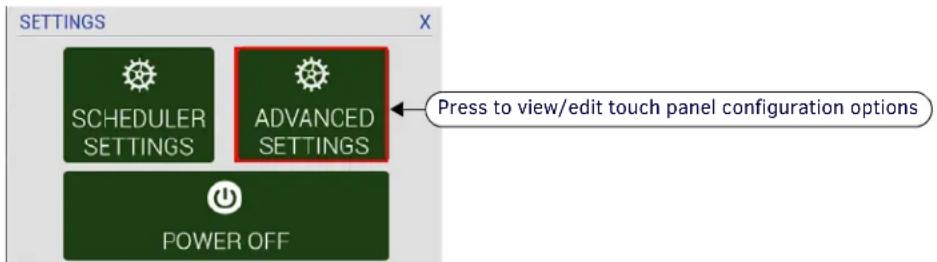
text_image
SETTINGS SCHEDULER SETTINGS ADVANCED SETTINGS Power OFF Press to view/edit touch panel configuration optionsFIG. 67 SETTINGS window - ADVANCED SETTINGS
NOTE: Alternatively, A long press of the room name (5 seconds minimum), will invoke the Settings window.
2. Press ADVANCED SETTINGS to access the Panels Settings menu.
NOTE: The panel will prompt you to enter the Administrator Password before opening protected Advanced Settings pages. The default Administrator password is "1988".
Using the Advanced Settings Menu
Many of the entries in the Advanced Settings menu are read-only. Information on the Device Info page (the initial view) will update when modified on subsequent pages.
The information on each Settings page appears in white under the main category title. Press the text to edit that field. Gray text indicates that the option associated with that category is disabled for editing. This may be altered with changes in connectivity (connecting a USB stick to the panel, for instance) or changes to other pages within the menu.
Advanced Settings Menu Options
The Advanced Settings Menu is separated into four main pages: INFO, DEVICE, CONNECTIONS, and SYSTEM:
| Advanced Settings Menu Options | ||
| Page Name Description | Page # | |
| INFO (initial view) | ||
| Device Info | Displays basic panel information, such as available memory and screen resolution dimensions. | page 44 |
| Maintenance | Provides control of basic panel functions, including rebooting or shutting down the panel. | page 45 |
| DEVICE | ||
| Sound Allows adjustment of volume levels and panel sounds settings. page 46 | ||
| Display Provides controls for basic functions of the panel display, including brightness. page 47 | ||
| VNC | Enables/disables and configures VNC server functionality on the panel. | page 49 |
| CONNECTIONS | ||
| Ethernet | Allows configuration of Ethernet communication settings with the panel. | page 50 |
| SYSTEM | ||
| Date & Time | Allows setting and adjusting of time and date information on the panel. | page 52 |
| Language & Input | Controls the language used by the Advanced Settings menu, as well as the keyboard input used for data entry | page 53 |
| Security | Allows setting or changing the admin password for this panel as well as managing CA Certificates. | page 57 |
| Reset and Update | Allows resetting and updating of panel settings and firmware. | page 61 |
| Diagnostics | Displays the current processor temperature, provides access to panel logs. | page 65 |
NOTE: The DEVICE, CONNECTIONS, ACCOUNTS, and SYSTEM pages are password-protected. The default Administrator password is "1988", and can be changed via the options in the SECURITY page - see Changing the Administrator Password on the Panel on page 33 for details.
Opening Advanced Settings pages
- Select the appropriate page from the Advanced Settings menu.
- In the Password keypad, enter the Administrator password and select OK.
NOTE: The default password is "1988".
Closing the Advanced Settings menu
To close the Advanced Settings menu and return to the panel's scheduling pages, select the Return icon at the bottom of the Advanced Settings window (see FIG. 68).
INFO - Device Info
The INFO - Device Info page (FIG. 68) displays basic panel information, such as available memory and screen resolution dimensions (read-only).
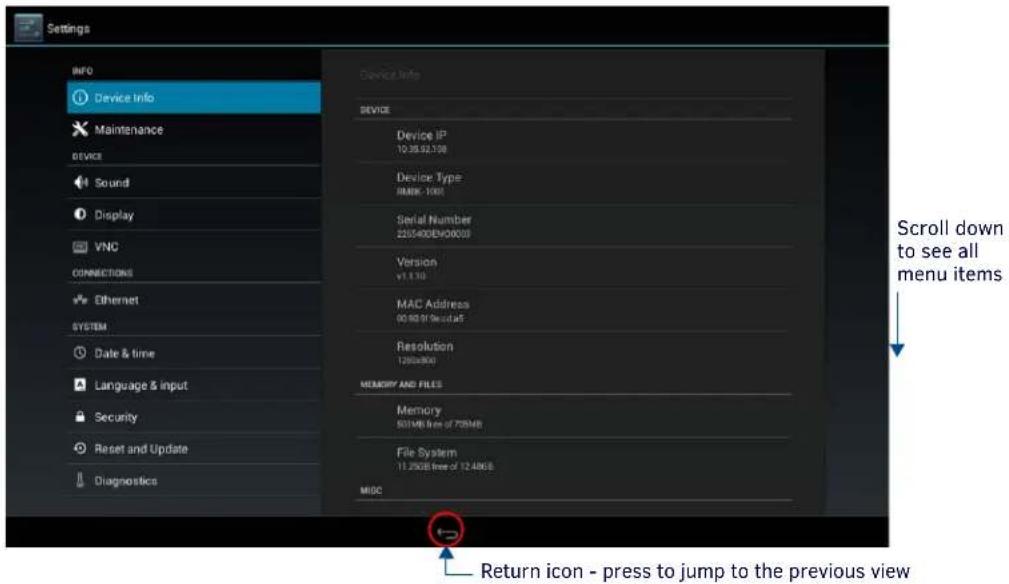
text_image
Settings INFO Device Info Maintenance DEVICE Sound Display VNC CONNECTIONS Ethernet SYSTEM Date & time Language & input Security Reset and Update Diagnostics Device Info DEVICE Device IP 10.35.92.108 Device Type JIMRK-1001 Serial Number 2255400EHO0000 Version v1.130 MAC Address 00.99 GB Security Resolution 12900800 MEMORY AND FILES Memory 501MB free of 728MB File System 11.2608 free of 12.4868 MISC Return icon - press to jump to the previous view Scroll down to see all menu itemsFIG. 68 INFO - Device Info page
| INFO - Device Info page options | |
| DEVICE | |
| Device IP Displays the panel's IP address. | |
| Device Type Displays the panel model. | |
| Serial Number Displays the specific serial number value assigned to the panel. | |
| Version Displays the current version of the panel's firmware. | |
| MAC Address Displays the panel's MAC address. | |
| Resolution Displays the panel's screen height and width in pixels. | |
| MEMORY AND FILES | |
| Memory Displays the amount of memory available on the panel. | |
| File System Displays the amount of MicroSD card memory available on the panel. | |
| MISC | |
| Up Time Displays the time elapsed since the panel was last started. | |
| Legal Information | Select this entry to open the Legal Information window, which displays information on intellectual property notices and information on copyright concerns. |
INFO - Maintenance
The INFO - Maintenance page (FIG. 69) provides control of basic panel functions, including rebooting or shutting down the panel.

text_image
Settings INFO Device Info Maintenance Device Sound Display VNC CONNECTIONS Ethernet SYSTEM Date & time Language & input Security Reset and Update Diagnostics Maintenance Reboot Shutdown Return icon - press to jump to the previous viFIG. 69 INFO - Maintenance page
| INFO - Maintenance page options | |
| Reboot: | Select this entry to open the Reboot window. |
| Shutdown: | Select this entry to open the Shutdown window. |
Rebooting the Panel
- In the Maintenance page, select Reboot. This opens the Reboot window (FIG 70).
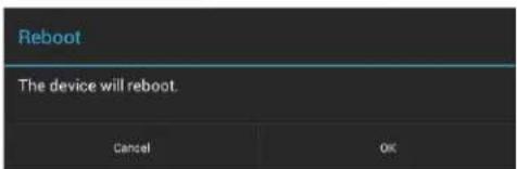
text_image
Reboot The device will reboot. Cancel OKFIG. 70 Reboot window
- Press OK to reboot.
To return to the Maintenance page without rebooting, press Cancel (or press outside the Reboot window).
Shutting Down the Panel
- In the Maintenance page. select Shutdown. This opens the Shutdown window (FIG. 71):

text_image
Shutdown The device will shutdown. Cancel OKFIG. 71 Shutdown window
- Press OK to shut down the panel.
To return to the Maintenance page without shutting down the panel, press Cancel (or press outside the Shutdown window).
DEVICE - Sound
The Sound page (FIG. 72) allows adjustment of volume levels and panel sounds settings.
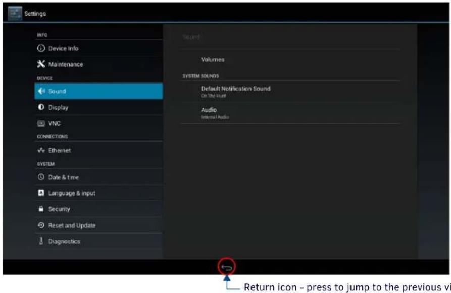
text_image
Settings INFO Device Info Maintenance DEVICE Sound Display VNC CONNECTIONS Ethernet SYSTEM Date & time Language & input Security Reset and Update Diagnostics Sound Volumes SYSTEM SOUNDS Default Notification Sound On The Host Audio Internal Audio Return icon - press to jump to the previous viFIG. 72 DEVICE - Sound page
| Sound page options | |
| SOUND | |
| Volumes | Press to open the Volumes window, which provides options to adjust volume for Music, video, games and other media as well as Notifications and Alarms. See the Adjusting Volumes section on page 46 for details. |
| SYSTEM SOUNDS | |
| Default Notification Sound: | Select this entry to choose a default notification sound from the menu provided. See Selecting a Default Notification Sound section on page 46. |
| Audio: | Displays the current audio options. The current and only available option is "Internal Audio". |
Adjusting Volumes
In the Sound page, press Volumes icon (FIG. 73) to open the Volumes window (FIG. 73):

text_image
Volumes Music videos games & other media Notifications Alumni OKFIG. 73 Sound page - Volumes window
Use these controls to adjust all of the available volume controls on the panel.
Press OK to save changes and close the Volumes window.
To return to the Sound page without saving changes, press outside the Volumes window.
Selecting a Default Notification Sound
To select a particular sound to be the default notification sound for all panel functions:
- In the Sound page, under SYSTEM SOUNDS, select Default Notification Sound. This opens the Default notification sound window (FIG. 74):
- Choose a sound from the presented list: selecting a new sound will play it once. The sound will only be audible if the Notifications slide bar in Volumes is not muted.
- Press OK to set the selected sound as the Default Notification Sound.
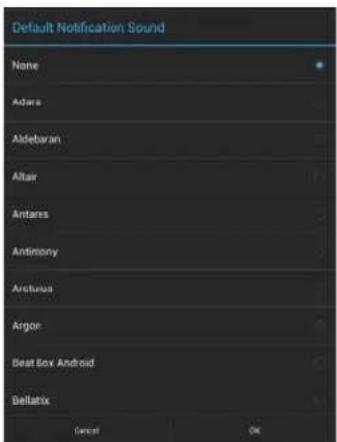
text_image
Default Notification Sound None Adara Aldebaran Altair Antares Antimony Aristacus Argon Beat Box Android Bellatrix Cancel OKFIG. 74 Default Notification Sound window
To return to the Sound page without making any changes, press Cancel (or press outside the Default Notification Sound window).
DEVICE - Display
The Display page (FIG. 75) controls the basic functions of the panel display, including the panel brightness, display timeout settings and touch calibration.
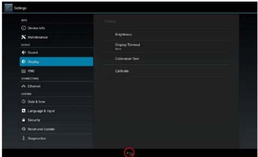
text_image
Settings INFO Device Info Maintenance DEVICE Sound Display VNC CONNECTIONS Ethernet SYSTEM Date & time Language & input Security Reset and Update Diagnostics Display Brightness Display Timeout None Calibration Test Calibrate
Return icon - press to jump to the previous view
FIG. 75 DEVICE - Display page
| DEVICE - Display page options | |
| Brightness: | Sets the display brightness and contrast levels of the panel. SeeAdjusting Panel Brightnesson page 47 for details. |
| Display Timeout: | Indicates the length of time that the panel can remain idle before the display automatically powers down.Select the Display Timeout setting. Range = 30 seconds, 1, 5, 10, 30 minutes, 1, 2, 4 and 8 hours. The default setting is 8 hours. Set the timeout value toNoneto disable Display Timeout mode.See theAdjusting Display Timeouton page 48 for details. |
| Calibration Test: | Select this to open theCalibration Testpage. SeeCalibration Teston page 48 for details. |
| Calibrate: Select to | open the Calibrate window,t o manually calibrate the panel. SeeCalibrateon page 49 for details. |
Adjusting Panel Brightness
- In the Display page, select Brightness to open the Brightness window (FIG. 76).
- Use the slidebar for manual adjustment of the panel's display brightness.
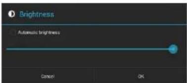
text_image
Brightness Automatic brightness Cancel OKFIG. 76 Brightness window
- Press OK to save changes and close this window.
To return to the Display page without making any changes, press Cancel (or press outside the Brightness window).
Adjusting Display Timeout
- In the Display page, select Display Timeout to open the Display Timeout window (FIG. 77).
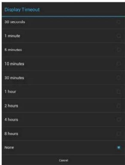
text_image
Display Timeout 30 seconds 1 minute 5 minutes 10 minutes 30 minutes 1 hour 2 hours 4 hours 8 hours None CancelFIG. 77 Display Timeout window
- Select the time period that will pass before the panel enters sleep mode, or select None to keep the panel from shutting down its display. The default settings is 8 hours. When a timeout setting is selected, the Display Timeout window closes immediately, having applied the selected setting.
To return to the Display page without making any changes, press Cancel (or press outside the Display Timeout window).
Calibration Test
Acendo Book panels automatically self-calibrate on startup. The Calibration Test page may be used to verify the accuracy of that calibration. Select Calibration Test to open the Calibration Test page (FIG. 78):

text_image
Options Touch Screen to Test ExitFIG. 78 Calibration Test menu
NOTE: In order to ensure a correct calibration upon starting, the panel display should not be touched while the panel is booting.
To run a calibration test on the touch panel:
- In the Display page, select Calibration Test.
- Touch the screen to test the calibration.
- For options when testing the calibration of the touch panel, select Options to open the Calibration Test Options window (FIG. 79).
- Fade is the default setting: it causes the cursor to fade away after touching; press it again to retain all touches on the display screen. Select this option to disable the Fade feature.
- Press Clear to clear the memory of previous touches. When finished, select Exit to return to the Calibration Test page.
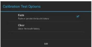
text_image
Calibration Test Options Fade Fade or persist the touch history Clear Clear the touch history ExitFIG. 79 Calibration Test Options window
- When finished with the calibration test, select Exit to return to the Display page.
Calibrate
To manually calibrate the panel:
- Select Calibrate to open the Calibrate window.
- Follow the on-screen instructions.
DEVICE - VNC
An on-board VNC (Virtual Network Computing) server allows the panel to connect to any remote PC running a VNC client. Once connected, the client can view and control the panel remotely. The options on the VNC page (FIG. 80) allow you to enable or disable VNC server functionality on the panel.

text_image
Settings INFO Device Info Maintenance DEVICE Sound Display VNC CONNECTIONS Ethernet SYSTEM Date & time Language & input Security Reset and Update Diagnostics VNC Enable/Disable ON VNC SERVER Timeout 15 mins Password Port $000 Current Connections 10:35:02:56 Maximum Connections 2 Return icon - press to jump to the previous viFIG. 80 DEVICE - VNC page
| DEVICE - VNC page options | |
| VNC | |
| Enable/Disable: | Press to toggle on/off the VNC server on the panel (default = enabled) |
| VNC SERVER | |
| Timeout: | Sets the length of time (in minutes) that the panel can remain idle, detecting no cursor movements, before the VNC session is terminated. (default = 15 minutes). |
| Password: Enter the VNC | Authentication session password required for VNC access to the panel. |
| Port: Use this field to enter the number of the port used by the VNC Web Server. Note that this field is enabled only while VNC is disabled (default = 5900). | |
| Current Connections: Displays the number of users currently connected to this panel via VNC (read-only). | |
| Maximum Connections: | Displays the maximum number of users that can be simultaneously connected to this panel via VNC. Press this field to increase the number allowed to connect to this panel. (default = 2). |
NOTE: The VNC server takes snapshots of the display buffer and sends them via VNC at a low frame rate.
Enabling VNC
In the VNC page, press Enable/Disable to toggle VNC to ON (the default setting is OFF).
Configuring VNC Access
In the VNC page, use the options under VNC SERVER to configure various aspects of VNC access on the panel:
- Press Timeout to specify a timeout period for VNC connections, in the Timeout window. Press OK to save changes.
- Press Password to assign the password to be required to establish a VNC connection, in the Password window. By default, no VNC password is set. Press OK to save changes.
- Press Port to specify the port to be used by the VNC Web Server, in the Port window. This option is not available if VNC is currently enabled. Press OK to save changes.
- Press Maximum Connections to set the maximum number of users that can be simultaneously connected to this panel via VNC. Press OK to save changes.
CONNECTIONS - Ethernet
The Ethernet page (FIG. 81) controls the configuration of settings for Ethernet communication with the panel.
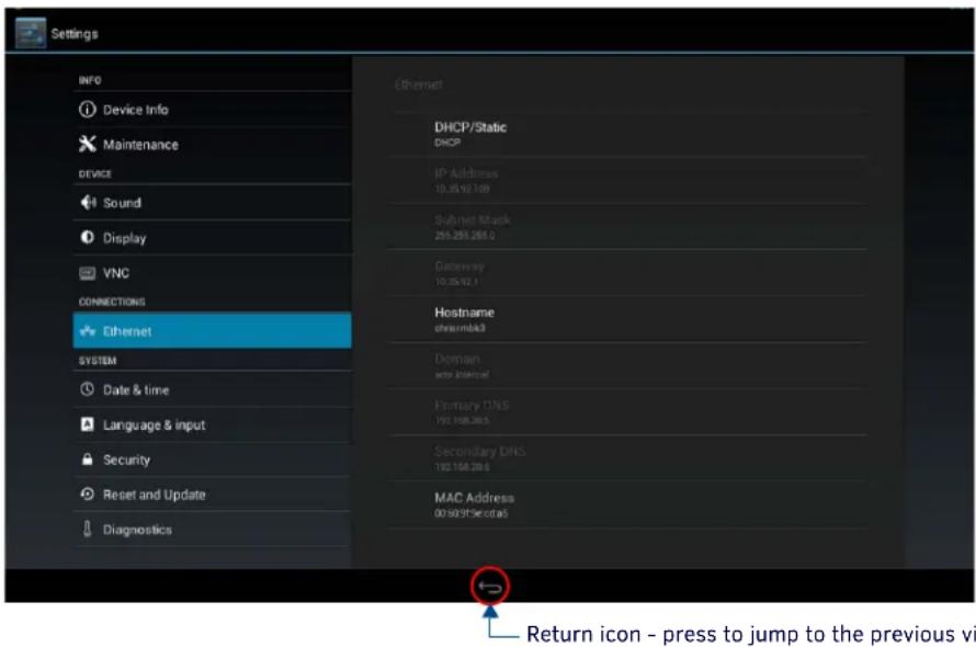
text_image
Settings INFO Device Info Maintenance DEVICE Sound Display VNC CONNECTIONS Ethernet SYSTEM Date & time Language & input Security Reset and Update Diagnostics Ethernet DHCP/Static DHCP IP Address 10.35.92.189 Subnet Mask 255.285.285.0 Gateway 10.35.92.1 Hostname cremdb3 Domain user specialized Primary DNS 192.168.203 Secondary DNS 192.168.203 MAC Address 00:50:91:Secitas Return icon - press to jump to the previous viFIG. 81 CONNECTIONS - Ethernet page
| CONNECTIONS - Ethernet page options | |
| DHCP/Static: Sets the panel to either DHCP or Static communication modes.DHCP is an IP Address assigned to the panel by a DHCP server. If DHCP is selected, the other Network Connection fields are disabled (see below).Static IP is a permanent IP Address assigned to the panel. If Static IP is selected, the other Network Connection fields are enabled. | |
| IP Address: | Displays the IP address for this panel. If DHCP is enabled, this field will be disabled. |
| Subnet Mask: | Displays the subnetwork for this panel. If DHCP is enabled, this field will be disabled. |
| Gateway: | Displays the gateway address for this panel. If DHCP is enabled, this field will be disabled. |
| Hostname: Displays the hostname for this panel. | |
| Domain: Displays a name to the panel for DNS look-up. If DHCP is enabled, this field will be disabled. | |
| Primary DNS: | Displays the address of the primary DNS server used by this panel for host name lookups. If DHCP is enabled, this field will be disabled. |
| Secondary DNS: | Displays the secondary DNS address for this panel. If DHCP is enabled, this field will be disabled. |
| MAC Address: This unique address identifies the Ethernet connection in the panel (read-only). | |
Setting Static IP Information
When using DHCP settings for a panel, the DHCP server will automatically populate almost all of the Ethernet page fields, with the exception of Hostname. When setting the panel for Static, however, this information must be entered manually. To enter the network connection information:
- Press DHCP/Static to access the DHCP/Static options window (FIG. 82):
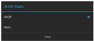
text_image
DHCP/Static DHCP Static CancelFIG. 82 DHCP/Static window
To return to the Ethernet page without making any changes, press Cancel (or press outside the DHCP/Static window).
- Press Static to select to use Static IP information, and open the Static IP window (FIG. 83).
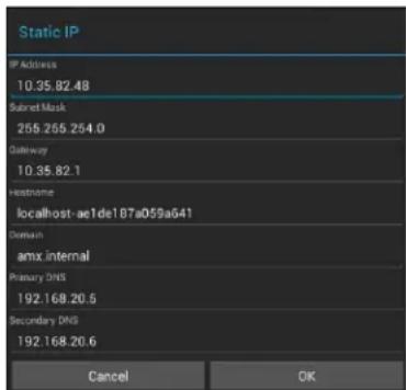
text_image
Static IP IP Address 10.35.82.48 Subnet Mask 255.255.254.0 Gateway 10.35.82.1 Hostname localhost-ae1de187a059a641 Domain amx internal Primary DNS 192.168.20.5 Secondary DNS 192.168.20.6 Cancel OKFIG. 83 Static IP window
-
Press any field in this window to open the on-screen keypad.
-
Enter the information for each field presented.
-
If the field accepts alphanumeric characters, a keyboard opens instead.
-
Press Next (in the on-screen keypad) to proceed to the next field.
-
When complete, press OK to save changes and return to the Static IP window. The new connection information is presented in the Ethernet page.
To return to the Ethernet page without making any changes, press Cancel (or press outside the Static IP window).
Entering a New Hostname
In order to facilitate DNS lookup of the panel, you should set a new hostname for the panel.
To add a new hostname, or to change an existing one:
- From the Ethernet page, select Hostname to open the Hostname window (FIG. 84).

text_image
Hostname localhost-7c4f800884b6fa18 Cancel OKFIG. 84 Hostname window
- Enter the new hostname and press OK. The new hostname will now appear in the Hostname field.
To return to the Ethernet page without making any changes, press Cancel (or press outside the Hostname window).
SYSTEM - Date & Time
The Date & Time page (FIG. 85) allows setting and adjusting the NTP/time and date information on the panel.

text_image
Settings INFO Device Info Maintenance DEVICE Sound Display VNC CONNECTIONS Ethernet SYSTEM Date & time Language & input Security Reset and Update Diagnostics Date & time Set NTP server Default Select time zone GMT-06300 Central Standard Time Return icon - press to jump to the previous viFIG. 85 SYSTEM - Date & Time page
| SYSTEM - Date & Time page options | |
| Set NTP Server: | Date and time information is retrieved from an NTP Server. A default public NTP server is pre-configured on the panels. Press Set NTP Server option to manually specify a custom NTP Server (see below). |
| Select Time Zone: | Use the Select Time Zone window (FIG. 88) to select the current time zone. |
NOTE: The network configuration must allow the Acendo Book Scheduling panel to communicate with the specified NTP Server (default or custom) in order for the Acendo Book panel to function.
Manually Setting a Custom NTP Server
- In the Date & Time page, press Set NTP Server. This opens the Set NTP Server window (FIG. 86):
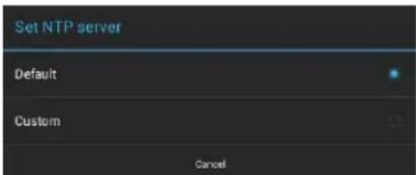
text_image
Set NTP server Default Custom CancelFIG. 86 Set NTP Server window
To return to the Date & Time page without making any changes, press Cancel (or press outside the Set NTP Server window).
- Select Custom to invoke the NTP Server window (FIG. 87):
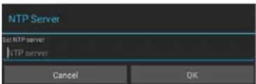
text_image
NTP Server Set NTP server NTP server Cancel OKFIG. 87 NTP Server window
- Press Set NTP server to enter the IP address of the NTP Server to use (via the on-screen keyboard).
- Press OK to save changes and close this window.
To return to the Date & Time page without making any changes, press Cancel (or press outside the NTP Server window).
Manually Setting the Time Zone
- Press Select Time Zone to open the Select Time Zone window (FIG. 88).
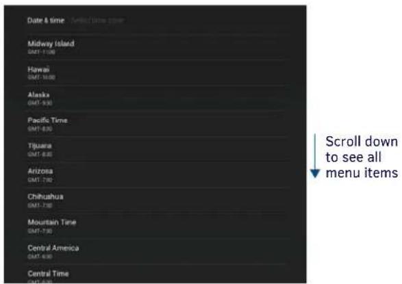
text_image
Date & time Midway Island GMT-7:00 Hawaii GMT-7:00 Alaska GMT-7:30 Pacific Time GMT-8:30 Tijuara GMT-8:30 Arizona GMT-7:30 Chihuahua GMT-7:30 Mountain Time GMT-7:30 Central America GMT-6:30 Central Time GMT-6:30 Scroll down to see all menu itemsFIG. 88 Select Time Zone window
- Select the time zone desired. The window will automatically close and return to the Date & Time page.
SYSTEM - Language & Input
The Language & Input page (FIG. 89) controls the language used by the Settings menu, as well as the keyboard input used for Settings menu field entries.

text_image
Settings INFO Device Info Maintenance DEVICE Sound Display VNC CONNECTIONS Ethernet SYSTEM Date & time Language & input Reset and Update Diagnostics Language & input Language English Spell checker Personal dictionary KEYBOARD & INPUT METHODS Default English (US) - System keyboard System keyboard English (US) PHYSICAL KEYBOARD Generic Default Auto-replace Correct in-shaped words Auto-capitalization Capitalize first letter in sentences Auto-punctuate Point Design key before to next * Return icon - press to jump to the previous view Scroll down to see all menu itemsFIG. 89 Language & Input page
| Language & Input page options | |
| Language: | Select a language for the Settings menu. See Selecting the Panel's Language on page 54 for details. |
| Spell Checker: | Enable this option to include an automatic spell checker In all Settings menu fields. |
| Personal Dictionary: | Lists all words saved in the panel's personal dictionary file. See Personal Dictionary on page 54 for details. |
| KEYBOARD & INPUT METHODS | |
| Default: | Specify the default system keyboard. Refer to Changing Input Methods on page 55 for details. |
| System Keyboard: | Choose the keyboard matching the selected panel language, or another language-format keyboard. Refer to Changing Input Methods on page 55 for details. |
| PHYSICAL KEYBOARD | |
| Generic: Selects the format for a physical keyboard connected to the panel. | |
| Auto-Replace: Select this for automatic correction of commonly mistyped words. | |
| Auto-Capitalization: | Select this for automatic capitalization of the first word in a sentence. |
| Auto-Punctuate: | Select this for automatic addition of a period when the space key is pressed twice. |
Language & Input page options (Cont.)
MOUSE/TRACKPAD
Pointer Speed: Provides the ability to adjust the speed of the cursor on the panel. Refer to Changing the Pointer Speed on page 56 for details.
Selecting the Panel's Language
English is the default language for Acendo Book panels, but this may be changed at any time through the Language & Input page. To change the panel's language:
- In the Language & Input page, press Language to open the Language window (FIG. 90).
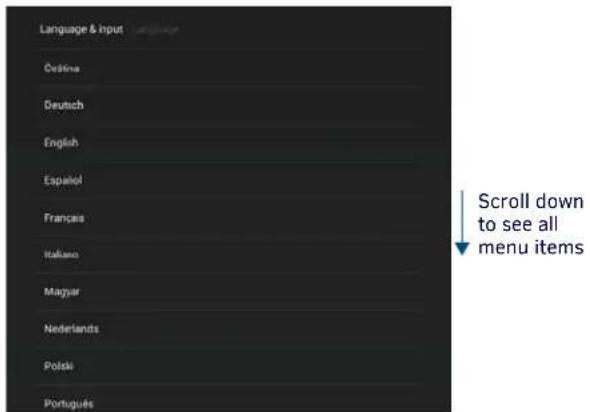
text_image
Language & Input Cristina Deutsch English Español Français Italiano Magyar Nederlands Polski Portugues Scroll down to see all menu itemsFIG. 90 Language Selection window
- Choose a language from the list shown. To return to the default language without making any changes, select Language & input at the top of the window to close the window.
Personal Dictionary
Acendo Book panels have automatic spell-checking capabilities. Additionally, words and phrases may be added to the panel's personal dictionary:
- In the Language & Input page, press Personal dictionary to open the Personal Dictionary window (FIG 91).

text_image
Language & input Acendo Back RMBK-1001 Press ADD (+)to add a word or phrase to the dictionary for this panel Custom words that have been added to this panel's dictionaryFIG. 91 Personal Dictionary window
- Press the Add button in the upper right hand corner of the page to open the Personal dictionary entry window.
- Press in the field beneath PHRASE to open the Personal Dictionary keyboard, and enter the word or phrase (FIG. 92):
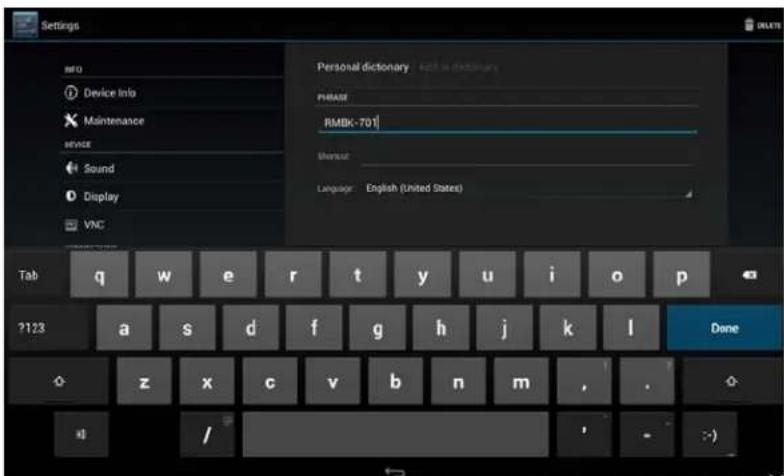
text_image
Settings INFO Device Info Maintenance SERVICE Sound Display VNC Personal dictionary and in dictionary PHASE RMBK-701 Shenout Language: English (United States) Tab q w e r t y u i o p ?123 a s d f g h j k l Done z x c v b n m , . / >FIG. 92 Personal Dictionary (Add window and Keyboard shown)
- To add a shortcut for long or complex words, enter it in the Shortcut field.
- If the word you add is in a language other than English, select the arrow in the lower right corner of the window to open the Language menu. This gives you the option of adding the word to the English dictionary, a dictionary for a language other than English, or for use across all languages. The Language page will automatically close after the language is selected.
-
To delete a word or phrase, select it in the Personal dictionary window and then press Delete in the upper right hand corner of the Settings menu.
-
Press Done to close the keyboard and add the specified word or phrase to the panel's dictionary.
Changing Input Methods
While a standard English keyboard is the default input language, you may also change the input method, such as choosing a Dvorak keyboard. To change the keyboard layout:
- In the Language & Input page, under KEYBOARD & INPUT METHODS, press Default to open the Choose Input Method window (FIG. 93):
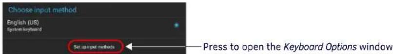
text_image
Choose input method English (US) System keyboard Set up input methods Press to open the Keyboard Options windowFIG. 93 Choose Input Method window
- Press Set up input methods to open the Keyboard Options window (FIG. 94).
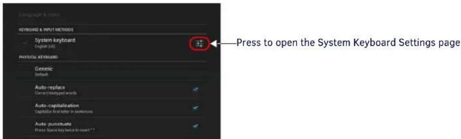
text_image
Keyboard & INPUT METHODS System keyboard English (alt) PHYSICI: KEYBOARD Generic Default Auto-replace Correct synthesized words Auto-capitalization Capabilities and letter in sentences Auto-punctuate Press Stock key twice to start**. Press to open the System Keyboard Settings pageFIG. 94 Keyboard Options window
- Press the Settings icon next to System keyboard to access the System Keyboard Settings page (FIG 95):

text_image
System keyboard settings Input languages English (0%) GENERAL Auto-capitalization Capacities like the word of use in performance Sound-on keypress TEXT CONNECTION Auto-correction Operator and punctuation automatically correct mycycled words Show correction suggestions Manage icons GESTURE TYPING Enable gesture typing Input a word by sliding through the letters Dynamic floating preview Use the suggested word while generating Show gesture trail OTHER OPTIONS Next-word suggestions Use the previous word in making suggestions Return icon - press to return to the Keyboard Options window Scroll down to see all menu itemsFIG. 95 System Keyboard Settings page
- Edit these settings as desired, and press the return icon to close this page and return to the Keyboard Options window.
- Under PHYSICAL KEYBOARD, press Generic to open the Choose Keyboard Layout window (FIG. 96):
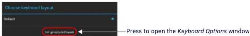
text_image
Choose keyboard layout Default Set up keyboard layouts Press to open the Keyboard Options windowFIG. 96 Choose Keyboard Layout window
- Press Set up keyboard layouts to open the Keyboard Layout window (FIG. 97):

text_image
Settings INFO Device Info Maintenance Service Sound Display VNC CONNECTIONS Ethernet SYSTEM Date & time Language & input Security Reset and Update Diagnostics Keyboard Layouts Czech SystemKeyboard Danish SystemKeyboard English (UK) SystemKeyboard English (US) SystemKeyboard English (US) Divorok style SystemKeyboard Estonian SystemKeyboard Finnish SystemKeyboard French SystemKeyboard French (Canada) SystemKeyboard German Return icon - press to save selections and open the Choose keyboard layout window Scroll down to see all menu itemsFIG. 97 Keyboard Layout window (indicating three layouts selected)
- Select the desired keyboard layout(s).
The selected layouts will be available for selection via the Choose Input Method window (select Default under KEYBOARD & INPUT METHODS to access).
- Press the return icon to close the Keyboard Layouts window and open the Choose Keyboard Layout window (FIG. 98):
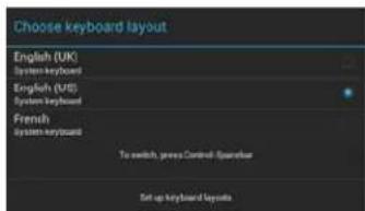
text_image
Choose keyboard layout English (UK) System keyboard English (US) System keyboard French system keyboard To switch, press Control, Operator Set up keyboard layoutsFIG. 98 Choose Keyboard Layout window
- Select the desired layout (or press outside of the window to close the Choose Keyboard Layout window without changing the selection) to return to the Keyboard Options window (FIG. 94 on page 55).
Changing the Pointer Speed
- Under MOUSE/TRACKPAD, press Pointer Speed to open the Pointer Speed window (FIG. 99):
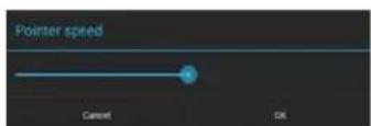
FIG. 99 Pointer Speed window
- Use the slide bar to choose the preferred speed.
- Press OK to save changes and close this window.
SYSTEM - Security
The Security page (FIG. 100) sets the admin password for this panel, and allows for the management of CA certificates.
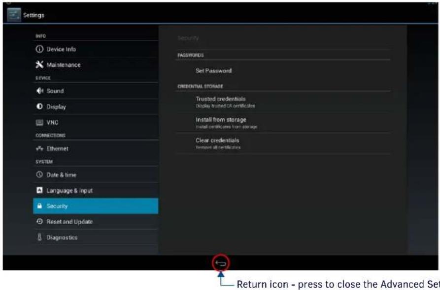
text_image
Settings INFO Device Info Maintenance DEVICE Sound Display VNC CONNECTIONS Ethernet SYSTEM Date & time Language & input Security Reset and Update Diagnostics Security PASSWORDS Set Password CREDENTIAL STORAGE Trusted credentials Display trusted OR certificates Install from storage Install certificates from storage Clear credentials Remove all certificates Return icon - press to close the Advanced SetFIG. 100 Security page
| Security page options | |
| PASSWORDS | |
| Set Password: | Specify the default admin password for this panel. See the Setting a Password for This Panel section on page 57 for details. |
| CREDENTIAL STORAGE | |
| Trusted Credentials | Press this option to view a listing of all trusted CA certificates currently loaded on this panel (SYSTEM level certificates and USER level certificates). See the Viewing Trusted CA Certificates (System/User) section on page 58 for details. |
| Install from Storage | Press this option to install CA Certificates on this panel via USB. See the Installing Certificates section on page 60 for details. |
| Clear Credentials | Press this option to clear all credentials from this panel. See the Clearing Credentials section on page 60 for details. |
Setting a Password for This Panel
- In the Security page, press Set Password to invoke the Enter Password dialog (FIG 101):
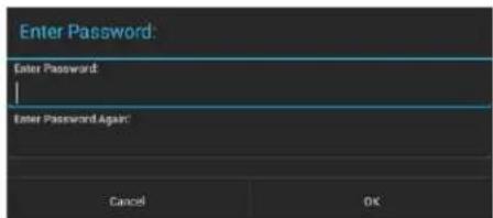
text_image
Enter Password: Enter Password: Enter Password Again: Cancel OKFIG. 101 Enter Password dialog
- Enter the new password in the first text field.
- Enter the new password again in the second text field.
- Press OK to close this dialog and save the new password.
Viewing Trusted CA Certificates (System/User)
- In the Security page, under CREDENTIAL STORAGE, press Trusted Credentials to invoke the Trusted Credentials page (FIG. 101):
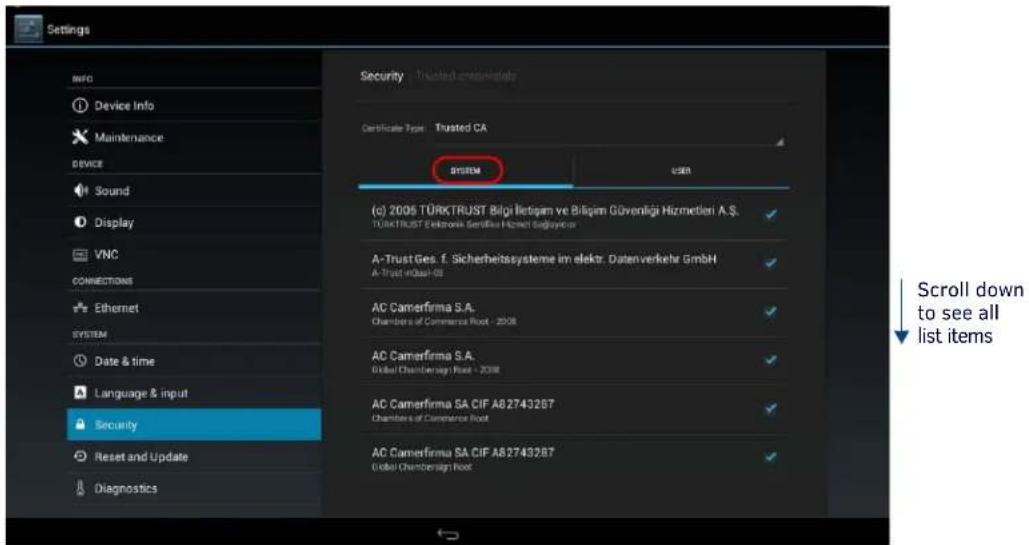
text_image
Settings INFO Device Info Maintenance DEVICE Sound Display VNC CONNECTIONS Ethernet SYSTEM Date & time Language & input Security Reset and Update Diagnostics Security Trusted credentials Certificate Type Trusted CA SYSTEM USER (c) 2005 TÜRKTRUST Bilgi İletişim ve Bilşim Güvenliği Hizmetleri A.Ş. TÜRKTRUST Einköneik Sertifikat Hizmeti Sağlık Sonder A-Trust Ges. f. Sicherheitssysteine im elektr. Datenverkehr GmbH A-Trust inbağlı 03 AC Camerfirma S.A. Chambers of Commerce Root - 2008 AC Camerfirma S.A. Global Chambersign Root + 2008 AC Camerfirma SA CIF A82743287 Chambers of Commerce Root AC Camerfirma SA CIF A82743287 Global Chambersign Root Scroll down to see all list itemsFIG. 102 Trusted Credentials page - SYSTEM list
The listing of trusted CA certificates is separated into two categories: System and User. The initial view of the Trusted Credentials page is the SYSTEM list (an example is shown in FIG. 102).
NOTE: It may be necessary to scroll down to view the entire list.
To view a listing of User-level certificates currently loaded on this panel, press USER in the Trusted Credentials page (FIG. 103):
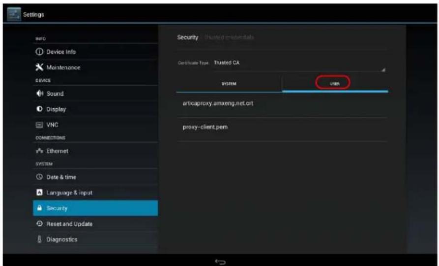
text_image
Settings INFO Device Info Maintenance DEVICE Sound Display VNC CONNECTIONS Ethernet SYSTEM Date & time Language & input Security Reset and Update Diagnostics Security: Trusted graduate Certificate Type: Trusted CA SYSTEM USER articaproxy.amxeng.net.crt proxy-client.pemFIG. 103 Trusted Credentials page - USER list
Disabling and Enabling Trusted CA Certificates
System certificates that are currently enabled are indicated with a blue checkmark. Note that by default, all installed certificates are enabled, as indicated in FIG. 104:

text_image
Security / Trusted credentials Certificate Type: Trusted CA SYSTEM USER (c) 2005 TÜRKTRUST Bilgi İletişim ve Bilgim Güvenliği Hizmetleri A.Ş. TÜRKTRUST Deterskı Gembüli Homet Sağlanması A-Trust Ges. f. Sicherheitssystemeim elektr. Datenverkehr GmbH A-Trust vQul-93 AC-Camerifma S.A. Chambers of Cunmeli ve Rist - 2008 AC-Camerifma S.A. Global Chambersign Nost - 2008 AC-Camerifma SA CIF A82743287 Chambers of Cunmeli ve Rist AC-Camerifma SA CIF A82743287 Global Chambersign Nost Enable/Disable security certificatesFIG. 104 System CA Certificates list - indicating all security certificates are enabled
To disable a system certificate, press to select a system certificate. This invokes the Security certificate details dialog for the selected certificate. An example is shown in FIG. 105:

text_image
Security certificate Issued by: Common name: Chambers of Commerce Unit - 2008 Organization: AC CameraForma S.A. Organizational unit: Serial number: WCA3DA627E A451-A451A Issued by: Common name: Chambers of Commerce Unit - 2008 Organization: AC CameraForma S.A. Organizational unit: Validity: Issued on: 5/1/2008 Expens on: 1/31/2008 Fingerprints: SHA-256 Singapore: 36.3E-4A7A.C491DP 07.3E.F3 DE 98.6E.KD AS 17.3E.RED TRES E 4.4E 10.47.95.TE22 ND 96.92C0 SHA-1 Singapore: TEGA-FADU.NR 14.4Y 90SA-DB/SBA DE AR 37.5F 54 CCK Disable this security certificate OKFIG. 105 Example Security certificate details dialog
To disable this system certificate, press the Disable button. The panel will prompt you to verify this action (press OK to proceed):

FIG. 106 Disabling a System Certificate
FIG. 107 shows an example of a disabled system certificate (FIG. 107):
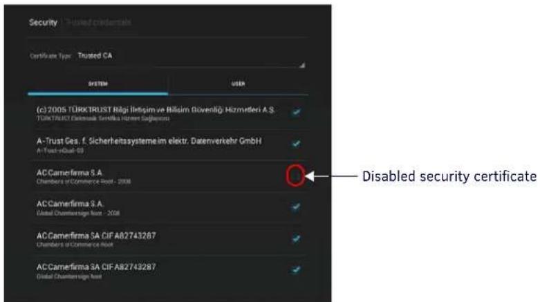
text_image
Security | Trusted credentials Certificate Type: Trusted CA SYSTEM USER (c) 2005 TÜRKTRUST Böls İletişim ve Bilisim Güvenliği Hizmetleri A.S. TÜRKTRUST Çelensuk Gembüli Hörnet Sağlancı A-Trust Ges. f. Sicherheitssysteme im elektr. Datenverkehr GmbH A-Trust-eQual-03 AC Camerfirma S.A. Chambers of Commerce Bank - 2008 AC Camerfirma S.A. Global Counter-tsign Noa - 2008 AC Camerfirma SA CIF A82743287 Chambers of Commerce Bank AC Camerfirma SA CIF A82743287 Global Counter-tsign Noa Disabled security certificateFIG. 107 System CA Certificates list - indicating all security certificates are enabled
NOTE: Disabled system certificates can be enabled later; disabled system certificates are not cleared from the panel (see the Clearing Credentials section on page 60).
To enable a system certificate, select a disabled system certificate. This invokes the Security certificate details dialog for the selected certificate. An example is shown in FIG. 105:
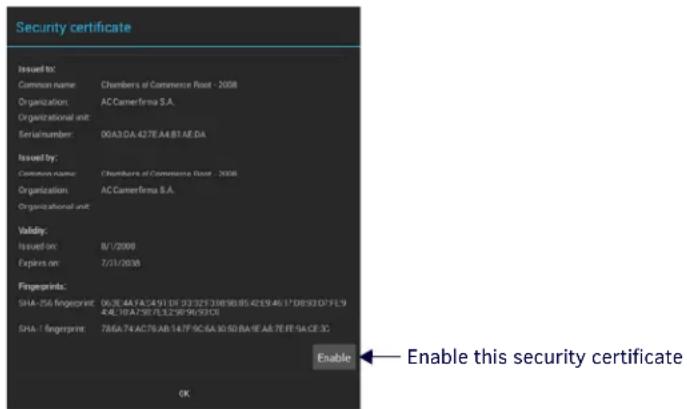
text_image
Security certificate Issued to: Common name: Chambers of Commerce Road - 2008 Organization: AC Camerfirma S.A. Organizational unit: Serial/number: 00A3DA 427E A4 B1 AE DA Issued by: Common name: Chumbers of Commerce Road - 2008 Organization: AC Camerfirma S.A. Organizational unit: Validity: Issued on: 8/1/2008 Explars on: 7/21/2008 Fingerprints: SHA-256 fingerprint: 062E AA FA 2491 DE 02325 3389B 85 42E9 4617 DB 93D 7FE 9 4EA 10A 7FE 132*96*93C0 SHA-1 fingerprint: 786A 74AC76AB 147F 9C-BA 3050 BA-FE A8 7FE 9A CF-3C Enable Enable this security certificate OKFIG. 108 Example Security certificate details dialog (for a disabled system certificate)
To enable this system certificate, press the Enable button. The panel will prompt you to verify this action (press OK to proceed):

text_image
Enable the system certificate? Cancel OKFIG. 109 Enabling a System Certificate
Installing Certificates
System certificates can be installed to the panel via USB, using the Install From Storage option on the Security Settings page.
- System certificates can be used with Microsoft Exchange and Office 365 Calendar setups (see FIG. 25 on page 24).
-
Supported certificate file extensions are: *.crt, *.pem and *.der.
-
Insert an external USB storage device into the USB port on the Acendo Book panel.
NOTE: The USB port extends from the bottom of the panel (see FIG. 19 on page 20 and FIG. 20 on page 21).
- In the Security page, under CREDENTIAL STORAGE (see FIG. 100 on page 57), press Install From Storage to invoke the Certificate File Browser page (FIG. 110):

text_image
Certificate File Browser USB No filesFIG. 110 Certificate File Browser page
Clearing Credentials
To clear all security credentials (CA certificates) from this Acendo Book Panel:
- In the Security page, press Clear Credentials.
- The panel will prompt you to verify this action (FIG. 111):

text_image
Attention Remove all the contents? Cancel OKFIG. 111 Verify Clearing Credentials from this panel
- Press OK to proceed (or press Cancel to return to the Security page without clearing credentials.
SYSTEM - Reset and Update
The Reset and Update page (FIG. 112) allows resetting and updating of panel settings and firmware, including installation of new firmware from an external drive.
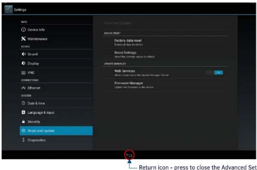
text_image
Settings INFO Device Info Maintenance DEVICE Sound Display VNC CONNECTIONS Ethernet SYSTEM Date & time Language & input Security Reset and Update Diagnostics Reset and Update DEVICE RESET Factory data reset Events of data entry devices Reset Settings Reset the Settings values to default UPDATE MANAGER Web Services Allow connection to the Update Manager Server ON Firmware Manager Update the firmware on the device Return icon - press to close the Advanced SetFIG. 112 Reset and Update page
| Reset and Update page options | |
| DEVICE RESET | |
| Factory Data Reset Erases | all data on the panel and resets the panel back to it's factory default settings.See Factory Data Reset on page 61 for details. |
| Reset Settings | Select to revert the panel back to its default settings, but does not erase all data from the panel. Note that the panel will be rebooted.See Reset Settings on page 62 for details. |
| UPDATE MANAGER | |
| Web Services | Use this switch to toggle Update Manager Web Services on the panel: If this switch is on, the Update Manager will attempt to connect to the Update Manager Server (hosted on amx.com). If the switch is off, then the Update Manager will not attempt to connect to the Update Manager Server. |
| Firmware Manager | Select to open the Firmware Manager page. Use the options on this page to update the firmware on the panel.See the Firmware Manager section on page 62 for details. |
Factory Data Reset
To reset the panel to its factory defaults and remove all data stored in the panel (including user pages):
- Under DEVICE RESET, press Factory Data Reset to open the Factory Data Reset window (FIG. 113).

text_image
Reset and Update / Factory Default This will erase all data from your device and reset it to factory defaults Reset deviceFIG. 113 Factory Data Reset window
To return to the Reset and Update page without making any changes, press Reset and Update.
- To erase all data from the panel, press Reset Device.
NOTE: The Scheduling Panel Setup Wizard will be launched again if a Factory Data Reset is performed on the panel (see page 22).
Reset Settings
To reset the Settings values to their default values:
- Under DEVICE RESET, press Reset Settings.
- The panel will prompt you to verify this action (FIG. 114):
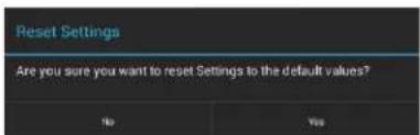
text_image
Reset Settings Are you sure you want to reset Settings to the default values? No YesFIG. 114 Reset Settings prompt window
- Press Yes to proceed. To return to the Reset and Update page without saving any changes, press No.
NOTE: The Scheduling Panel Setup Wizard will be launched again if a Reset Settings is performed on the panel (see page 22).
Enable/Disable Web Services
This option enables/disables Web Services on this Acendo Book panel (FIG 115):

text_image
Web Services Allow connection to the Update Manager ServerFIG. 115 UPDATE MANAGER - Web Services option
Web Services allow the Acendo Book panel to connect to the Update Manager server, to receive firmware updates from www.amx.com. By default, this option is enabled (ON).
To disable Web Services on this panel, toggle this option to OFF.
Firmware Manager
Select Firmware Manager under UPDATE MANAGER in the Reset and Update page to access the Firmware Manager page (FIG. 116):

text_image
Firmware Manager Revert To Factory Firmware version: USB Install Firmware From USB No Web Updates Available UPDATE UPDATEFIG. 116 Firmware Manager page
Reverting to Factory-Installed Firmware
In certain circumstances, it may be necessary to uninstall the current firmware on a panel and return it to the original factory default firmware. To reset the panel to its original factory firmware:
- From the Firmware Manager window, select UPDATE next to Revert to Factory Firmware (FIG. 117):

text_image
Revert To Factory Firmware version 0.0.6 UPDATEFIG. 117 Firmware Manager - Revert To Factory Firmware
- A System Message window is displayed that indicates the factory firmware version that will be installed, and prompting you to verify this action (FIG. 118):

text_image
Revert To Factory Firmware 1.1.17 Do you want to install this firmware? Cancel OKFIG. 118 System Prompt - Revert To Factory Firmware?
- Select OK to install the previous firmware version and Cancel to return to the Firmware Manager.
- If you choose OK, the panel will reboot and restart with the factory installed firmware.
NOTE: Resetting the panel to its original factory firmware will remove all updates made to the Settings menu since that version.
Installing New Firmware From An External USB Stick
To install new firmware to the panel from a USB stick:
- Download the latest Acendo Book panel firmware from www.amx.com and save it to a USB stick or other external drive with USB capability.
NOTE: The firmware can be saved at the root directory, or be saved in a folder in the USB stick directory. The folder name is not case sensitive. - Insert the USB stick into an available USB port. This may require disassembling wall-mounted panels to access the USB ports if a USB extension was not already installed.
- From the Firmware Manager window (FIG. 116 on page 62), select UPDATE next to Install Firmware from USB (FIG. 119):

text_image
Install Firmware From USB UPDATEFIG. 119 Firmware Manager - Install Firmware from USB
- The KIT File Browser window presents a listing of firmware available on the USB stick (FIG. 120):

text_image
KIT File Browser USB 1-17-2014 1-27-2014 System Volume Information Test KIT SW2265_RoomBook_v0_0.14.kitFIG. 120 KIT File Browser window
- Select the KIT file to be installed.
- The panel will prompt you to verify this action. Press OK to proceed (FIG 121):

text_image
SW2265_RoomBook_v0_0_14.kit Do you want to install this firmware? Cancel OKFIG. 121 Verify Firmware Installation
- The panel will upload the new firmware (FIG. 122) and then reboot.
text_image
AMV 4.1AFIG. 122 Update Progress display
Install Firmware From Web
This option provides the ability to download new panel firmware from AMX, and install it on the Acendo Book panel.
If a firmware update is available for the panel, the Install Firmware From Web option is presented on the Firmware Manager page (see FIG. 116 on page 62), indicating the firmware version that is available to download from AMX and install on the Acendo Book panel.
NOTE: If this option is not included on the Firmware Manager page, this panel already has the most recent firmware.
To install new firmware to the panel from the web:
- From the Firmware Manager window (FIG. 116 on page 62), select UPDATE next to Install Firmware from Web (FIG. 123):

FIG. 123 Firmware Manager - Install Firmware from Web
NOTE: Press README to view any notes associated with the selected firmware file (press Close to close the README window).
- The panel will prompt you to verify this action - Press OK to proceed with the update (FIG. 124):
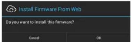
text_image
Install Firmware From Web Do you want to install this firmware? Cancel OKFIG. 124 System Prompt - Install Firmware From Web
- The progress of the download is indicated on the Firmware Manager page (FIG. 125).
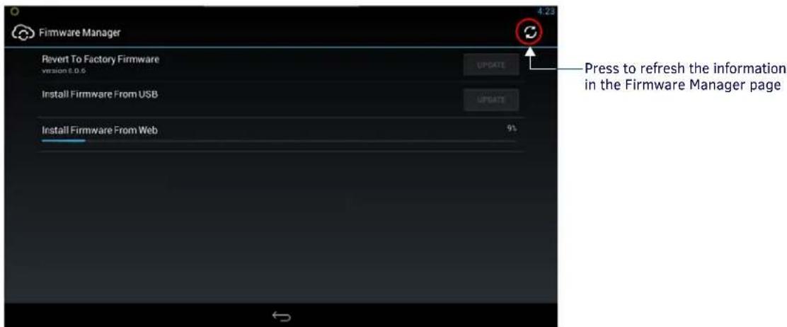
text_image
Firmware Manager Revert To Factory Firmware version 6.0.6 UPDATE Install Firmware From USB UPDATE Install Firmware From Web 9% Press to refresh the information in the Firmware Manager pageFIG. 125 Firmware Manager page - Install Firmware From Web (In progress)
NOTE: Press the Refresh icon to refresh the information on this page, if necessary.
- The firmware update will begin the install process (FIG. 126):

text_image
Firmware Update Preparing Firmware...FIG. 126 Firmware Update - Preparing Firmware
- After copying the firmware package to the staging location, the panel will reboot and complete the firmware installation process (FIG. 127):
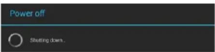
text_image
Power off Shutting down.FIG. 127 Firmware Update - reboot and complete firmware update
Using AMX System Recovery
During a normal firmware upgrade, if a Acendo Book panel is unable to boot all the way, AMX System Recovery can be used to try to reset system data or re-install firmware. To initiate system recovery:
- Power up the panel while holding the Sleep/Settings button.
- Release the button 3 seconds after seeing the AMX boot logo, and wait a few seconds for recovery mode to begin.
-
A text screen titled "AMX System Recovery" is displayed, presenting the following options:
-
Reboot Device
-
Factory Data Reset
• Revert to Factory Firmware
• Install Firmware from USB -
Navigate the menu options by pressing the Sleep/Settings button.
To select an item, press and hold the Sleep/Settings button for 2 or more seconds. Alternatively, if the panel has a USB keyboard plugged in at bootup, use the Up/Down arrows and Enter keys to navigate the menus.
- Select Reboot Device to reboot the panel.
- Select Factory Data Reset and then select Yes on the confirmation window to erase all of the user data (settings, application data, user pages) on the panel.
- Select Revert to Factory Firmware and then select Yes on the confirmation window for the system to extract the factory firmware (this can take a minute) and then automatically initiate a firmware upgrade as usual.
- Select Install Firmware from USB for a new menu to come up, where the user can navigate the files on the USB drive. Selecting the "..// " entry will take the user back to the previous directory. Entries with a trailing "/" on the name are directories, and selecting a directory will bring up a new menu with the contents of that directory shown. All other entries will be ".kit" files. Selecting a KIT file and selecting Yes on the confirmation screen will extract the firmware (this can take a minute) and then automatically initiate a firmware upgrade as usual.
SYSTEM - Diagnostics
The Diagnostics page (FIG. 128) displays the current processor temperature and provides access to panel logs.

text_image
Settings INFO Device Info Maintenance DEVICE Sound Display VNC CONNECTIONS Ethernet SYSTEM Date & time Language & input Security Reset and Update Diagnostics Diagnetics Temperature 50°C Logs Return icon - press to close the Advanced SettFIG. 128 Diagnostics page
| Diagnostics page options | |
| Temperature D | splays the current temperature of the panel in Celsius. |
| Logs Select this | option to display the panel logs. |
The Logs window chronicles all previous connections between the panel and the network. To access the Logs window, select Logs in the Diagnostics page.
Acendo Book Scheduling Panels - User Guide
Overview
This section describes using Acendo Book Touch Panels that have been installed and configured. In this section, "Room" refers to the Room associated with a Acendo Book panel.
Room Available Page
If the Room is currently available, the Room Available page is displayed (FIG. 129):

text_image
Room Name Meeting Room 1a Room schedule (use scroll buttons to view all) 3 PM 4 PM Scroll Up/Down buttons AVAILABLE 2:55 PM Monday, February 15 Book ROOM Room Status Time/Date Press to schedule a meetingFIG. 129 Room Page - AVAILABLE
When the Room Available Page is displayed, the Room Status LEDs light green, unless the LEDs have been disabled via the "Room Status LED" option in the Room setup page (see the Viewing/Editing Room Settings section on page 42).
NOTE: Room Status may not be shown if a custom logo is in use.
Room Occupied Page
If the Room is currently in use for a scheduled meeting, the Room Occupied page is displayed.
The information and options displayed are identical to the ROOM AVAILABLE page - the only difference is the red color scheme (FIG. 130):

text_image
Meeting Room 1a Ad-Hoc Meeting 4 PM Project meeting 5 PM OCCUPIED 3:39 PM Monday, February 15 BOOK ROOMFIG. 130 Room page - OCCUPIED
When the Room Occupied Page is displayed, the Room Status LEDs light red, unless the LEDs have been disabled via the "Room Status LED" option in the Room setup page (see the Viewing/Editing Room Settings section on page 42).
Scheduling an Ad-Hoc Meeting
If the room is available, an ad-hoc meeting can be scheduled to start immediately:
- In the Room Available page, press BOOK ROOM (FIG. 131):
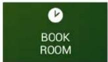
FIG. 131 BOOK ROOM button
- This invokes the BOOK ROOM page. Use the options in this page to change the default settings, as desired. By default, ad-hoc meetings are set to start immediately, and last for 30 minutes (FIG. 132):
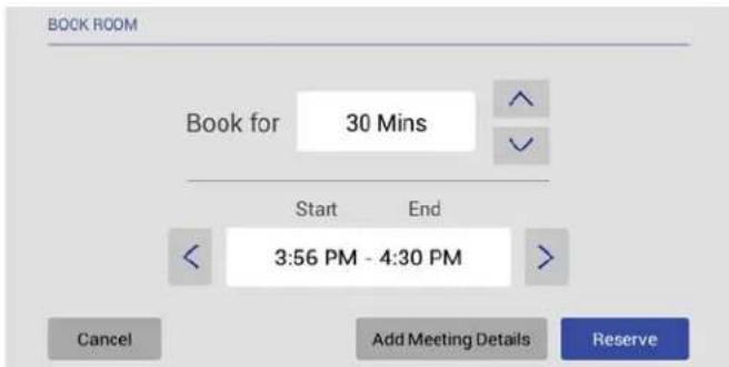
text_image
BOOK ROOM Book for 30 Mins Start End 3:56 PM - 4:30 PM Cancel Add Meeting Details ReserveFIG. 132 BOOK ROOM page
- Use the Book for Up/Down arrows to adjust the duration of the meeting (if necessary).
-
Use the Start/End Left/Right arrows to adjust the start time of the meeting (if necessary).
-
Press Reserve to reserve this room for the time allotted.
-
If prompted. enter the Meeting PIN Code (FIG. 133):
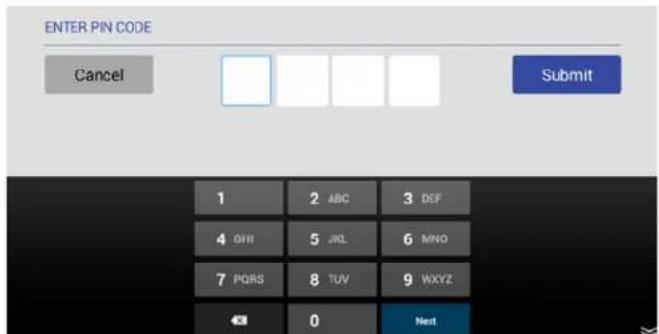
text_image
ENTER PIN CODE Cancel Submit 1 2 ABC 3 DEF 4 OFF 5 JKL 6 MNO 7 PQRS 8 TUV 9 WXYZ ← 0 NextNote: The Meeting PIN Code is only required if the "Meeting PIN Code" option is enabled in the Security setup page.
The Meeting PIN Code is set on the Security Setup page as well (see page 33 for details).
FIG. 133 ENTER PIN CODE
- Press Submit to reserve the meeting.
- Once the meeting has been added to the calendar, the Room page is changed to indicate that it is currently OCCUPIED (FIG. 134):
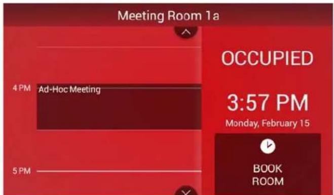
text_image
Meeting Room 1a 4 PM Ad-Hoc Meeting 5 PM OCCUPIED 3:57 PM Monday, February 15 BOOK ROOMFIG. 134 Room page (OCCUPIED)
Scheduling a Meeting for Later
To schedule a meeting for later in the day:
- In the Room page, press BOOK ROOM (FIG 135):
FIG. 135 BOOK ROOM button
NOTE: Meetings can be scheduled for a later time, regardless of whether the room is currently AVAILABLE or OCCUPIED.
- This invokes the BOOK ROOM page. Use the options in this page to change the default settings, as desired. By default, meetings are set to last for 30 minutes (FIG. 132):
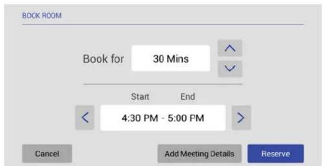
text_image
BOOK ROOM Book for 30 Mins Start End 4:30 PM - 5:00 PM Cancel Add Meeting Details ReserveFIG. 136 BOOK ROOM page
- Press Add Meeting Details to open the ADD MEETING DETAILS page (FIG. 137):
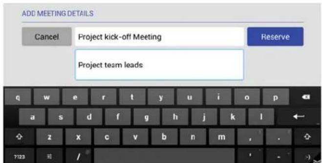
text_image
ADD MEETING DETAILS Cancel Project kick-off Meeting Reserve Project team leadsFIG. 137 ADD MEETING DETAILS page
-
Press Reserve to reserve the meeting as specified.
-
If prompted, enter the Meeting PIN Code (FIG. 138):

text_image
ENTER PIN CODE Cancel Submit 1 2 ABC 3 DEF 4 GHI 5 JKL 6 MND 7 PORS 8 TUV 9 WXYZ ← 0 NextFIG. 138 ENTER PIN CODE
-
Press Submit to reserve the meeting.
-
Once the meeting has been added to the calendar, it is represented on the Room page (FIG. 139):
Note: The Meeting PIN Code is only required if the "Meeting PIN Code" option is enabled in the Security setup page.
The Meeting PIN Code is set on the Security Setup page as well (see page 33 for details).
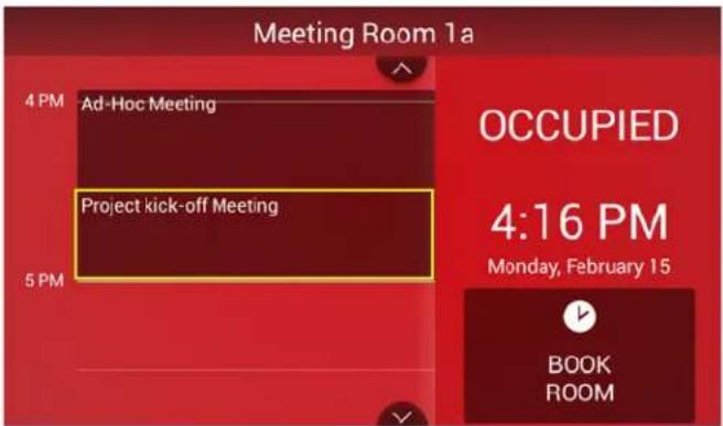
text_image
Meeting Room 1a 4 PM Ad-Hoc Meeting Project kick-off Meeting 5 PM OCCUPIED 4:16 PM Monday, February 15 BOOK ROOMFIG. 139 Room page
Browse Rooms for Scheduling
If this panel is part of a Group, the BROWSE ROOMS option allows you to browse other Acendo Book panels in the same Scheduling Group to check for availability. Other panels/rooms in the Group that are available can be scheduled from any panel in the group.
BROWSE ROOMS Button
- The BROWSE ROOMS button is always displayed on panels that are configured as a Member panel of a Scheduling Group (see Viewing/Editing Group Settings on page 41 for details on Scheduling Groups).
-
If the device is configured as the Master panel of a Scheduling Group, the BROWSE ROOMS button is automatically removed if no Member panels have communicated with the Master panel for 5 minutes.
-
In the Room page, press BROWSE ROOMS (FIG. 140):
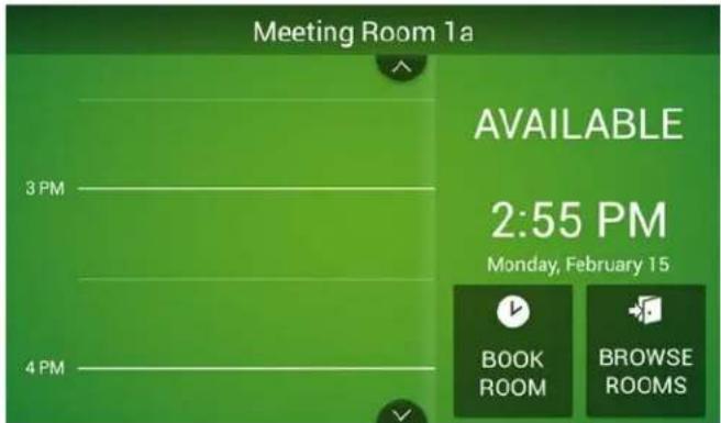
text_image
Meeting Room 1a AVAILABLE 2:55 PM Monday, February 15 3 PM 4 PM BOOK ROOM BROWSE ROOMSFIG. 140 BROWSE ROOMS button
- The AVAILABLE ROOMS page displays a list of the other Acendo Book panels in the Scheduling Group that are available for booking immediately.
NOTE: Rooms in the Scheduling Group that are not available for booking at the current time will not show up in the AVAILABLE ROOMS list, even though they may be available later.
The example in FIG. 141 shows that there are several other Acendo Book panels in the group, three of which are available for booking right now:

text_image
AVAILABLE ROOMS Muhammad Ali AVAILABLE NOW T.S. Eliot AVAILABLE NOW Winston Churchill AVAILABLE NOW Henry Ford AVAILABLE IN 51 MIN Rachel Carson NOT AVAILABLE ExitFIG. 141 AVAILABLE ROOMS page
Note that the AVAILABLE ROOMS page uses color coding to indicate which rooms in the group are currently available for booking (AVAILABLE NOW in green). Rooms that are unavailable at the moment indicate when they will be available for booking (AVAILABLE IN XX MIN in red). Rooms that are unavailable the rest of the day are listed as NOT AVAILABLE (in red).
- Press one of the rooms in the list to reserve or schedule a meeting in that room. This invokes the BOOK ROOM page (FIG. 142). Use the options in this page to set the meeting duration, start/end times, add meeting details, and reserve the room for the specified time:

text_image
BOOK ROOM Book for 15 Mins Start End 11:15 AM - 11:30 AM Cancel Add Meeting Details ReserveFIG. 142 BOOK ROOM page
a. Book for - Use the up/down arrow buttons to adjust the length of the meeting reservation (default = 15 minutes).
b. Start/End - Use the left/right arrow buttons to set the Start and End time of the meeting reservation (based on the specified Book for value).
c. Add Meeting Details - Press to open the ADD MEETING DETAILS page to enter a Subject and Comments for the meeting (FIG. 143):
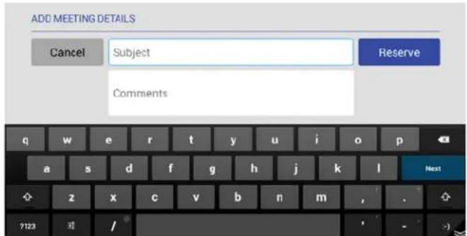
text_image
ADD MEETING DETAILS Cancel Subject Reserve Comments q w e r t y u i o p a s d f g h j k l Next z x c v b n m , . ?123 /FIG. 143 ADD MEETING DETAILS page
NOTE: The Add Meeting Details option will not be available if Privacy Mode is enabled.
d. Press RESERVE to add this meeting to the selected panel's schedule.
Viewing/Editing Meeting Details
Press on any scheduled meeting on the Room Page to open the MEETING DETAILS page for the selected meeting (FIG. 144):

text_image
Meeting Room 1a MEETING DETAILS Meeting Organizer —— Troller Account Subject —— Project kick-off Meeting Start/End Time —— 4:30 PM - 5:00 PM Comments —— Project team leads Exit Edit Meeting Details Edit Meeting Time DeleteFIG. 144 MEETING DETAILS page
This page indicates the current Title, Start/End Times and Comments associated with the selected meeting. The buttons along the bottom of this page allow you edit the selected meeting's Meeting Details, Start/End Time, as well as to delete this meeting from the calendar.
- If Privacy Mode is on, Meeting Organizer and Comments are not displayed,
- If Privacy Mode is on, the Edit Meeting Details button is not provided.
- If the meeting was NOT scheduled via the Acendo Book panel (i.e. directly via the Email/Web client software), the Edit Meeting Details, Edit Meeting Time and Delete buttons are disabled.
Editing Meeting Details
- In the MEETING DETAILS page, press Edit Meeting Details to open the EDIT MEETING DETAILS page (FIG. 145):
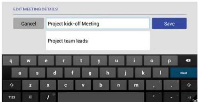
text_image
EDIT MEETING DETAILS Cancel Project kick-off Meeting Save Project team leads q w e r t y u i o p a s d f g h j k l Next z x c v b n m , . ?123 /FIG. 145 EDIT MEETING DETAILS page
- Press inside the first text field to edit the Meeting Title text via the on-screen keyboard.
- Press inside the second text field to edit the Meeting Details text via the on-screen keyboard.
- Press Save to save changes.
- If prompted, enter the Meeting PIN Code in the ENTER PIN CODE page (FIG. 146):
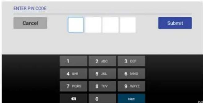
text_image
ENTER PIN CODE Cancel Submit 1 2 ABC 3 DEF 4 SHI 5 JKL 6 MNO 7 PQRS 8 TUV 9 WXYZ ← 0 NextNote: The Meeting PIN Code is only required if the "Meeting PIN Code" option is enabled in the Security setup page.
The Meeting PIN Code is set on the Security Setup page as well (see page 33 for details).
FIG. 146 ENTER PIN CODE page
- Press Submit to return to the Room page.
Edits made for the selected meeting are reflected in the updated calendar.
Editing Meeting Times
- In the MEETING DETAILS page, press Edit Meeting Time to open the EDIT MEETING TIME page (FIG. 147):

text_image
EDIT MEETING TIME Book for 1 Hour Start End 5:00 PM - 6:00 PM Cancel SaveFIG. 147 EDIT MEETING TIME page
-
Press Save to save changes.
-
If prompted, enter the Meeting PIN Code in the ENTER PIN CODE page (FIG. 148):
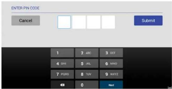
text_image
ENTER PIN CODE Cancel Submit 1 2 ABC 3 DEF 4 GHI 5 JKL 6 MNO 7 PQRS 8 TUV 9 WXYZ ← 0 NextNote: The Meeting PIN Code is only required if the "Meeting PIN Code" option is enabled in the Security setup page.
The Meeting PIN Code is set on the Security Setup page as well (see page 33 for details).
FIG. 148 ENTER PIN CODE page
- Press Submit to return to the Room page.
Edits made for the selected meeting are reflected in the updated calendar.
Deleting a Meeting From the Calendar
- In the MEETING DETAILS page, press Delete to open the DELETE MEETING (FIG. 149):
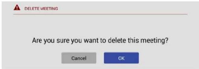
text_image
DELETE MEETING Are you sure you want to delete this meeting? Cancel OKFIG. 149 DELETE MEETING page
- Press OK to proceed.
- If prompted, enter the Meeting PIN Code in the ENTER PIN CODE page (FIG. 150):

text_image
ENTER PIN CODE Cancel Submit 1 2 ABC 3 DEF 4 GHI 5 JKL 6 MNO 7 POIRS 8 TUV 9 WXYZ 0 NextNote: The Meeting PIN Code is only required if the "Meeting PIN Code" option is enabled in the Security setup page.
The Meeting PIN Code is set on the Security Setup page as well (see page 33 for details).
FIG. 150 ENTER PIN CODE page
- Press Submit to return to the Room page.
The selected meeting is removed from the updated calendar (FIG. 151):
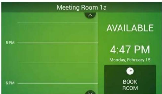
text_image
Meeting Room 1a AVAILABLE 4:47 PM Monday, February 15 BOOK ROOMFIG. 151 Room page
Appendix A: Troubleshooting
Overview
This section provides information to help address several potential issues relative to Acendo Book Scheduling panels and supported Scheduling services. Please check these topics before contacting AMX Technical Support.
| Acendo Book Scheduling Panels - Troubleshooting Topics | |
| Problem Possible Solution(s) | |
| NO CALENDAR SERVER CONNECTION DETECTED -Username and Password | · Calendar Settings - Review the current Calendar settings (Username with domain, Password and Room account with domain). See Viewing/Editing Calendar Settings on page 39), and verify that the settings are correct.· Service Account Properties and Configuration - Review the Google Service account configuration. See Appendix D: Configuring Google Resources on page 82. |
| Meeting Room1a | |
| NO CALENDAR SERVER CONNECTION DETECTED | |
| Please check Username and Password.Contact Administrator to restore connection.Customer Support: 555-624-0000 | |
| NO CALENDAR SERVER CONNECTION DETECTED - SSL Certificate Time Validation | Verify that the current network configuration allows the panel to access the NTP Server specified on the panel.NTP-related settings are made via Advanced Settings on the panel (see the Advanced Settings section on page 43). In the Settings menu, select SYSTEM > Date & Time to access the Set NTP Server and Select Time Zone settings: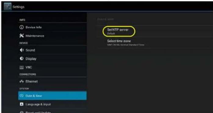 Check the current date/time. Time is displayed in the top right corner of each Advanced Settings page. If the time is incorrect, check the Set NTP Server setting:· If Default is selected, verify that the current network configuration is allowing NTP through the firewall.· I f Custom is selected, verify that:the specified URL is validthe specified NTP server is onlinethe current network configuration is allowing NTP through the firewall Check the current date/time. Time is displayed in the top right corner of each Advanced Settings page. If the time is incorrect, check the Set NTP Server setting:· If Default is selected, verify that the current network configuration is allowing NTP through the firewall.· I f Custom is selected, verify that:the specified URL is validthe specified NTP server is onlinethe current network configuration is allowing NTP through the firewall |
| Meeting Room | |
| NO CALENDAR SERVER CONNECTION DETECTED | |
| SSL Certificate time validation error.Contact Administrator to restore connection.Chris: 222-252-2525 | |
| This error indicates that the SSL certificate did not pass the date/time validation check, typically because the time on the Acendo Book Scheduling Panel is incorrect - this can cause the certificate to appear to have expired. | |
| Exchange: Intermittent issues connecting to calendar server'SSH logs show "The request failed. The server cannot service this request right now. Try again later."Problem Possible Solution(s) | Exchange throttling parameters may need to be adjusted. |
| Exchange: Meeting Reservation Not Indicated on the Panel (No Error Message)When reserving a meeting (in Exchange), the meeting never shows up on the Acendo Book panel, and the panel is not indicating an error. | The Exchange Administrator should create a Service Account and Room Delegate, and enable "Auto Accept" for meeting reservations from an Acendo Book panel, as described below:1) Creating a Service AccountThis simply a user account. The following command creates the service account for the room:New-Mailbox -Alias-Name-FirstName-LastName-DisplayName-UserPrincipalName-ResetPasswordOnNextLogon false2) Creating a Room DelegateThe following command creates the new mailbox for the room:New-Mailbox -Name-Alias-UserPrincipalName-FirstName-LastName-Room)The following command sets the various parameters for the previously created mailbox:Set-CalendarProcessing -Identity-DeleteCommentsfalse-DeleteSubject false-DeleteNonCalendarItemsfalse-AddOrganizerToSubject false-TentativePendingApprovalfalse-AutomateProcessing AutoAccept -AllowRecurringMeetings Strue-BookingWindowInDays 1080 -AllRequestOutOfPolicy false-AddNewRequestsTentativelyfalse -ProcessExternalMeetingMessages StruENOTE 1: In the case you want to set the ability to allow conflicting meeting requests to a room resource, you can use the AllowConflicts parameter with the Set-CalendarProcessing command.The AllowConflicts parameter specifies whether to allow conflicting meeting requests.Valid input for this parameter is true orfalse. The default value is false.NOTE 2: In the scenario that you do not want the recurring meetings rejected when they have an end date beyond the booking window; you will need to change the AllowConflicts parameter tofalse.When the AllowConflicts parameter is true, a recurring meeting request is automatically declined if the meetings start on or before the date specified by the BookingWindowInDays parameter, and the meetings extend beyond the specified date.When the AllowConflicts parameter isfalse, a recurring meeting request is automatically accepted if the meetings start on or before the date specified by the BookingWindowInDays parameter, and the meetings extend beyond the specified date. However, the number of meetings is reduced so meetings won't occur after the specified date.When BookingWindowInDays is 0, an end date isn't enforced for any recurring meetings.When BookingWindowInDays is greater than 0 and EnforceSchedulingHorizon is true, the recurring meeting request is automatically declined if the end date is greater that the value specified by BookingWindowInDays.When BookingWindowInDays is greater than 0 and EnforceSchedulingHorizon isfalse, the end date of a recurring meeting is automatically truncated to the value specified by BookingWindowInDays. The following command will change the default behavior:Set-CalendarProcessing -Identity-BookingWindowInDays 181-EnforceSchedulingHorizon falseSee Also:Configuring Delegation (Exchange 2010) on page 76Using Exchange Admin Center (EMC) on page 76Using PowerShell on page 773) Configure the Room to Auto AcceptThe AutomateProcessing parameter enables or disables calendar processing on the mailbox, and AutoUpdate sets it so that only the Calendar Attendant processes meeting requests and responses.Set-CalendarProcessing -Identity-AutomateProcessing AutoAccept |
| Acendo Book Scheduling Panels - Troubleshooting Topics (Cont.) | |
| Problem Possible Solution(s) | |
| Exchange/Off ice 365: Conflicting Meetings Indicated at Incorrect TimeIf a meeting is scheduled for a time that has already been reserved for a given room, It is a Conflicting Meeting. | If conflicts are allowed (in Exchange/Office 365), then conflicting meetings may be indicated at a time other than what was requested by the user. To disable conflicts in Exchange/Office 365, verify that the AllowConflicts property is set to False for the room with which the Acendo Book panel is associated.Once disabled, conflicting meetings will be declined by the scheduling system. To disable conflicts in Exchange/Office 365, verify that the AllowConflicts property is set to False for the room with which the Acendo Book panel is associated.Once disabled, conflicting meetings will be declined by the scheduling system. |
| Exchange/Office 365: The Meeting Subject shown on Acendo Book indicates the organizer of the meeting instead of the meeting subject | In order for the Acendo Book panel to be able to read the privacy mode flag, the Exchange resource's "-AddOrganizerSubject" has to be set tofalse.By default, this is set to true. |
| Exchange/Office 365: Private meeting flag not detected by Acendo Book panel | the Exchange resource's "--RemovePrivateProperty" has to be set tofalse.By default, this is set to $true. |
| Exchange/Office 365: Private meeting flag not updated when private flag is changed from checked to unchecked. | To change meeting from private to "visible", delete the meeting and re-enter it. |
| "Master Connection Error" DisplayedIf the Master panel goes offline for any reason, the Master panel as well as all Member panels in the Scheduling Group display the Master Connection Error message. | 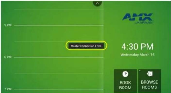 Check the connection status of the Master panel and verify that the network configuration. For example, has the Username, Password or IP Address of the Master Panel been changed?Once the Master panel is connected to the network, the Member panels should recover automatically. Check the connection status of the Master panel and verify that the network configuration. For example, has the Username, Password or IP Address of the Master Panel been changed?Once the Master panel is connected to the network, the Member panels should recover automatically. |
| (Google): Meetings Are Not Indicated on Room Page | Verify that the Auto-accept invitations that do not conflict property is selected for the room with which the Acendo Book panel is associated.See Appendix D: Configuring Google Resources on page 82 for details. |
| "Browse Rooms" Button Is Not Displayed On the Group MasterIf the master device does not have a Browse Rooms button, then a Member panel has not checked in with the Master panel in the last 5 minutes. | Verify that the Member panels are online and configured with the Scheduling Group Master panel's IP, username, and password. |
| The panel is locked, and the admin password has been lost or forgotten | If the administrator forgets the Administrator password, the panel can be reset to return the password to the default value ("1988") via the Factory Data Reset option.Note: In this event, all panel settings will be lost.Refer to the Using AMX System Recovery section on page 65 for details. |
Acendo Book Scheduling Panels - Troubleshooting Topics (Cont.)
A room listed in the Available Rooms screen (after pressing Browse Rooms) is always listed as "NOT AVAILABLE".
All Acendo Book scheduling panels in a Group must have firmware version 1.1.x or higher. Scheduling panels running version 1.0.x will not show availability information correctly.
Configuring Delegation (Exchange 2010)
The following example illustrates configuring a delegate that can manage scheduling for the Room Mailbox:
- In the Resource Policy tab of the mailbox Properties dialog, click Add
- Select the user that will become a delegate of the Room Mailbox (FIG. 152):
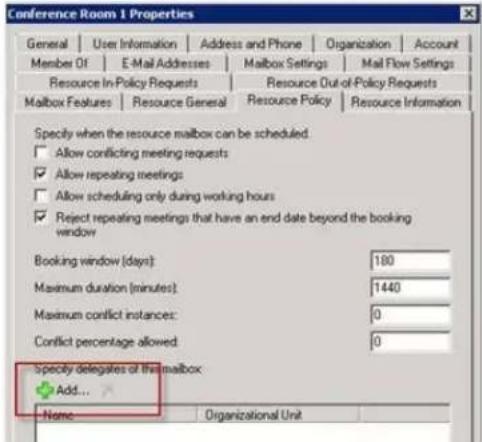
text_image
Conference Room 1 Properties General User Information Address and Phone Organization Account Member Of E-Mail Addresses Malbox Settings Mail Flow Settings Resource In-Policy Requests Resource Out-of-Policy Requests Malbox Features Resource General Resource Policy Resource Information Specify when the resource mailbox can be scheduled. Allow conflicting meeting requests Allow repeating meetings Allow scheduling only during working hours Reject repeating meetings that have an end date beyond the booking window Booking window (days) 180 Maximum duration (minutes) 1440 Maximum conflict instances: 0 Conflict percentage allowed 0 Specify delegates of the mailbox Add... Name Organizational UnitFIG. 152 Mailbox Properties dialog - Resource Profiles tab
Delegates also need Editor access to the calendar and free/busy folder of the mailbox itself so that they can manage meeting requests. There are two ways to achieve this:
- Option 1: Grant an administrator Full Access Permissions to the Room Mailbox, open it in Outlook, and edit the Calendar and Mailbox permissions.
- Option 2: Grant the delegate Full Access Permissions to the Room Mailbox
The following example uses Option #2:
Add-MailboxPermission -Identity "Delegation Room 1" -User rmsservice -AccessRights FullAccess The delegate rmsservice can now manage room bookings.
The example in FIG. 153 indicates a meeting that is still unconfirmed, waiting for rmsservice to approve or reject it:
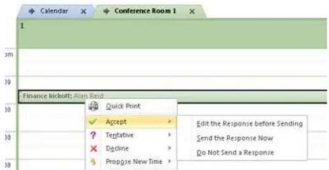
text_image
Calendar Conference Room 1 1 3m 30 Finance kickoff: Alan Reid 30 Quick Print Accept Edit the Response before Sending ? Teptative Send the Response Now × Decline Do Not Send a Response Propgise New TimeFIG. 153 Unconfirmed Meeting Indicated (waiting for rmsservice to approve or reject)
After rmsservice approves the meeting the organizer (in this example - "Alan Reid") receives a message confirming acceptance.
Using Exchange Admin Center (EMC)
NOTE: You need to have permissions assigned before you can perform this procedure. To see what permissions are required, see the "Resource Mailbox Configuration Permissions" section in the Mailbox Permissions topic.
- In the console tree, navigate to Recipient Configuration > Mailbox.
- In the result pane, select the resource mailbox that you want to configure.
- In the action pane, under the name of the resource mailbox, click Properties.
-
In
Properties, click the Resource Policy tab. -
Under Specify delegates of this mailbox, perform the following:
a. To add a resource delegate, click Add, and then select the recipient.
b. To remove a resource delegate, select the delegate, and then click Remove.
-
To forward all meeting requests to the delegates listed, select the Forward meeting requests to delegates option
-
Click Apply to save your changes, or click OK to save your changes and close the dialog.
Using PowerShell
NOTE: You need to have permissions assigned before you can perform this procedure. To see what permissions are required, see the "Resource Mailbox Configuration Permissions" section in the Mailbox Permissions topic.
The following example uses the primary SMTP address for Ed, Ayla, and Tony to set them as the delegates for the resource mailbox Room222:
Set-CalendarProcessing -Identity "Room222" -ResourceDelegates "ed@contoso.com", "ayla@contoso.com", "tony@contoso.com"
Appendix B: Configuring Acendo Book Panels for Microsoft Exchange & Office 365
Overview
This section provides information regarding setting up Acendo Book panels to communicate with Exchange 2010/2103/2016 or Office 365 Servers.
Acendo Book Service Account
The Acendo Book Service Account on the Exchange or Office 365 server must meet the following requirements:
- The account must have an associated Exchange Mailbox.
- The account information entered here must match the account information for the Acendo Book Service Account (as entered in the CALENDAR Settings page (see page 39).
-
The account must have rights to add, modify, and cancel/delete appointments in each Exchange Room Mailbox with which Acendo Book will synchronize. This may be accomplished via any of the following three methods:
-
Delegate access to the mailbox.
- Impersonate the mailbox owner using Exchange Impersonation.
- Assign full-access permissions to the mailbox.
Microsoft Exchange / Office 365: Username and Calendar Email IDs
The Exchange 2010/2103/2016 or Office 365 Server has a unique User Name for each user and a unique Calendar Email ID for each room. The Username and Calendar Email ID is entered for each room in the CALENDAR Settings page (see FIG. 56 on page 39).
To configure each Acendo Book user and room for use with Microsoft Exchange / Office 365:
- Enter the Username: Enter a valid name for a user with access rights that are appropriate for the room specified in the Calendar Email ID field (see below). The Username must include the fully qualified domain name
Example: JaneDoe@acme.onmicrosoft.com
- Enter the Calendar Email ID: Enter the email address for a valid room. The Calendar Email ID must include the fully qualified domain name.
Example: ConfRoom1@acme.onmicrosoft.com
NOTE: The Calendar Email ID field is the only field that is unique to each room: "Server URL", "username", and "password" are the same across all rooms in the system (FIG. 154):

text_image
SETTINGS Network Calendar Localization Group Room Security Calendar Server Office 365 Username JaneDoe@acme.onmicrosoft.com Password 12admin34 Calendar Email ID ConfRoom1@acme.onmicrosoft.com Certificate Validation Strict Exit Edit Calendar Server, Username and Password fields are the same for all rooms in the Exchange or Office 365 deployment Calendar Email ID and Certification Validation is unique for each roomFIG. 154 SETTINGS > Calendar page (showing sample Calendar information - Exchange/Office 365)
Microsoft Exchange / Office 365: Certificate Validation
The Exchange 2010/2103/2016 or Office 365 Server has a unique User Name for each user and a unique Calendar Email ID for each room. The Username and Calendar Email ID is entered for each room in the CALENDAR Settings page (see FIG. 56 on page 39).
Microsoft Documentation
The following links provide access to online Microsoft documentation regarding each of these methods for each supported Server OS:
| Exchange 2010 Set a Delegate on a Resource Mailbox: http://technet.microsoft.com/en-us/library/bb124973(v=exchg.141).aspx |
| Exchange 2013, Off ice 365 Delegating Permissions: http://technet.microsoft.com/en-us/library/jj215781%28v=exchg.150%29.aspx (go to Create a room mailbox > Use the EAC to create a room mailbox) Note: If you selected the option requiring that booking requests are sent to delegates, use this section to select delegates. To add a delegate, click Add. On the Select Delegates page, select a user, click Add, and then click OK to return to the New room mailbox page. To remove a delegate, select the user and then click Remove. Assigning Full-Access Permissions: http://technet.microsoft.com/en-us/library/jj919240%28v=exchg.150%29.aspx Configuring Impersonation: https://msdn.microsoft.com/en-us/library/office/dn722376(v=exchg.150).aspx |
| Exchange 2016, Off ice 365 Delegating Permissions: https://technet.microsoft.com/en-us/library/jj215781(v=exchg.160).aspx (go to Create a room mailbox > Use the EAC to create a room mailbox) Note: If you selected the option requiring that booking requests are sent to delegates, use this section to select delegates. To add a delegate, click Add. On the Select Delegates page, select a user, click Add, and then click OK to return to the New room mailbox page. To remove a delegate, select the user and then click Remove. Assigning Full-Access Permissions: https://technet.microsoft.com/en-us/library/jj919240(v=exchg.160).aspx Configuring Impersonation: https://msdn.microsoft.com/en-us/library/office/dn722376(v=exchg.150).aspx |
Configuring Exchange To Hide/Show Meeting "Organizer", "Title" and "Details"
For Exchange 2010, see information under Resource Information in the Use the EMC to configure resource mailbox properties section:
https://technet.microsoft.com/en-us/library/bb124255(v=exchg.141).aspx
Exchange 2013, 2016 and Exchange Online require the use of Exchange cmdlets to change the room mailbox properties.
The cmdlet of interest is the Set-CalendarProcessing which will allow you to configure what information Exchange provides to the Acendo Book panel.
Set-CalendarProcessing parameters of particular significance:
- AddOrganizerSubject
- DeleteComments
- DeleteSubject
Microsoft Documentation
The following links provide access to online Microsoft documentation that provide details needed to use the above mentioned cmdlet for each supported Server OS:
| Exchange Server 2010 | https://technet.microsoft.com/en-us/library/dd335046(v=exchg.141).aspx |
| Exchange Online, Exchange Server 2013 | https://technet.microsoft.com/en-us/library/dd335046(v=exchg.150).aspx |
| Exchange Online, Exchange Server 2016 | https://technet.microsoft.com/en-us/library/dd335046(v=exchg.160).aspx |
Privacy Flag
Acendo Book panels use Exchange, Office 365 or Google "privacy" flag. A meeting marked as private will behave the same way the global Acendo Book "Privacy Mode" behaves (see the Privacy Mode section on page 34).
In order for the Acendo Book panel to be able to read the privacy mode flag in Exchange and Office 365, the Exchange server must set the room's "-RemovePrivateProperty" to \false. By default, this is set to \true.
Appendix C: Creating Room Mailboxes
Overview
Exchange 2010, 2013, 2016 and Office 365 use Room Mailboxes to manage meeting room schedules. Each Acendo Book location (meeting room) that will synchronize with the Microsoft scheduling application (Exchange / Office 365) must be represented by a Room Mailbox.
NOTE: Appropriate administrator access is required to perform these tasks.
Creating a New Room Mailbox: Exchange 2010
- On the Exchange 2010 server, select Microsoft Exchange Server 2010 > Exchange Management Console to launch the Exchange Management Console utility.
- Under Recipient Configuration, right-click on Mailbox and select New Mailbox from the context menu. This selection opens the New Mailbox - Introduction dialog.
-
Select Room Mailbox, and click Next to proceed to the New Mailbox - User Type dialog.
-
Select either New User or Existing users:
-
New User - select this option to create a new user.
-
Existing users - select this option to assign an existing user that is not currently associated with an Exchange 2010 Mailbox.
-
Click Next to proceed to the New Mailbox - User Information dialog.
-
Fill in the user information fields in this dialog and click Next to proceed to the New Mailbox - Mailbox Settings dialog.
-
The default settings in this dialog are sufficient - click Next to proceed to the New Mailbox New Mailbox (Confirmation Summary) dialog.
-
Use this dialog to review the information entered.
-
To copy the summary information presented in this dialog, click CTRL+C.
-
Click New to create the new Mailbox, and proceed to the New Mailbox - Completion dialog.
-
Click Finish.
Repeat this process for each RMS Location that will synchronize with RMS.
Additional Documentation
For more detailed information on creating a room mailbox, creating a room list and changing room mailbox properties in Exchange 2010, refer to the Microsoft® article "Managing Resource Mailboxes and Scheduling":
http://technet.microsoft.com/en-us/library/bb124374(v=EXCHG.141).aspx
Note that this article also provides instructions on using the Exchange Management Shell to create room mailboxes and room lists.
Creating a New Room Mailbox: Exchange 2013 and Exchange 2016
- Log in to the Exchange Admin Center (EAC):
https://
- or -
https://
a. Provide your credentials to log into Exchange.
b. The Exchange Admin Center opens in your browser window.
-
Under Recipients, select Resources.
-
In the Resources page toolbar, click the Add (+) button then select Room mailbox to open the New Room Mailbox dialog.
-
Fill in the fields, and click Save to create the new mailbox and close the New Room Mailbox dialog.
NOTE: The only required fields in this dialog are Room name and Email address.
The new room should now be included in the list of Resources (on the Resources page).
-
Select the new mailbox and click Edit to open the Room Mailbox dialog. Use the options in this dialog to configure the new room mailbox.
-
Select Booking Delegates.
-
Under Booking requests, verify that Accept or decline booking automatically is selected (the default setting).
-
Click Save to save changes and close the New Room Mailbox dialog.
Repeat this process for each RMS Location that will synchronize with RMS.
Additional Documentation
For more detailed information on creating a room mailbox, creating a room list and changing room mailbox properties in Exchange 2013, refer to the Microsoft® article "Create and manage room mailboxes":
http://technet.microsoft.com/en-us/library/jj215781%28v=exchg.150%29.aspx
For more detailed information on creating a room mailbox, creating a room list and changing room mailbox properties in Exchange 2016, refer to the Microsoft® article "Create and manage room mailboxes":
https://technet.microsoft.com/en-us/library/jj215781(v=exchg.160).aspx
NOTE: These articles also provide instructions on using the Exchange Management Shell to create room mailboxes and room lists.
Creating a New Room Mailbox: Off ice 365
- Log in to the Exchange Admin Center (EAC):
https://outlook.office365.com/ecp/
a. Provide your credentials to log into Office 365.
b. The Exchange Admin Center opens in your browser window.
-
Under Recipients, select Resources.
-
In the Resources page toolbar, click the Add (+) button to open the New Room Mailbox dialog.
- Fill in the fields, and click Save to create the new mailbox and close the New Room Mailbox dialog.
NOTE: The only required fields in this dialog are Room name and Email address.
The new room should now be included in the list of Resources (on the Resources page).
-
Select the new mailbox and click Edit to open the Room Mailbox dialog. Use the options in this dialog to configure the new room mailbox.
-
Select Booking Delegates.
-
Under Booking requests, verify that Accept or decline booking automatically is selected (the default setting).
- Click Save to save changes and close the New Room Mailbox dialog.
Repeat this process for each RMS Location that will synchronize with RMS.
Additional Documentation
For more detailed information on creating a room mailbox, creating a room list and changing room mailbox properties in Office 365, refer to the Microsoft ^® article "Create and manage room mailboxes":
http://technet.microsoft.com/en-us/library/jj215781%28v=exchg.150%29.aspx
Note that this article also provides instructions on using the Exchange Management Shell to create room mailboxes and room lists.
Appendix D: Configuring Google Resources
Overview
This section provides instructions for configuring Google resources to work correctly with Acendo Book panels.
These instructions make the following assumptions:
• A Google Business Service account is available
- A Room Administrator account has been created that will be shared with each resource
The process of configuring Google resources for use with Acendo Book panels entails the following:
-
Create Resources (see below)
-
Share resource calendars with administrator - see page 84
-
Share service calendars with room administrator account - see page 85
-
Ensure calendar is set to deny conflicts - see page 86
1) Create Resources
- Log in to the Google Admin Console using the credentials for the Administrator account for Google Apps for Business used by Acendo Book (FIG. 155):
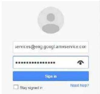
text_image
services@eng.googl.amxservice.com ************** Sign in □ Stay signed in Need hop?Note that your Google Admin Console user interface may vary slightly from the illustrations provided here, based on your specific software version. The concepts described in this section apply to all supported versions of Google for Business.
FIG. 155 Google Admin Console Login Screen
- In the Admin Console, select Apps (FIG 155):
≡ Admin console

Users
Add, rename, and manage users

Company profile
Update information
about your company

Billing
View charges and
manage licenses

FIG. 156 Google Admin Console (detail)
- In the Apps page, select Google Apps (FIG 157):
≡ Apps
APPS SETTINGS Marketplace settings

text_image
7 Google Apps Email, Calendar, Drive & more
text_image
14 Additional Google services Blogging, photos, video, social tools and more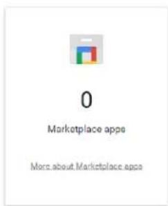
text_image
0 Marketplace apps More about Marketplace appsFIG. 157 Google Admin Console - Apps Page (detail)
- In the Google Apps page, select Calendar (FIG. 158):
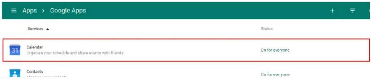
text_image
Apps > Google Apps Services ▲ Status 31 Calendar Organize your schedule and share events with friends On for everyone Contacts On for everyoneFIG. 158 Google Admin Console - Google Apps Page (detail)
- In the Calendar page, select Resources (FIG. 159):

text_image
Apps > Google Apps > Settings for Calendar 31 Calendar ON for everyone https://www.google.com/calendar/bioster/eng.googl.ameservice.com 3 Active users in last 7 days 33% Percent of users using this application Sharing settings Set global sharing policies for users' primary calendars. Resources Define resources that are available for users to schedule on their calendars, such as meeting rooms, projectors, company cars, or other shared equipment.FIG. 159 Google Admin Console - Calendar Page (detail)
- In the Resources pane, select Create a new resource (FIG. 160):
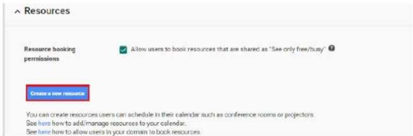
text_image
Resources Resource booking permissions ✓ Allow users to book resources that are shared as "See only free/busy" Create a new resource You can create resources users can schedule in their calendar such as conference rooms or projectors. See here how to add/manage resources to your calendar. See here how to allow users in your domain to book resourcesFIG. 160 Google Admin Console - Calendar Page - Resources Pane (detail)
- Define the Resource Name, Resource Type and Description (FIG. 161):
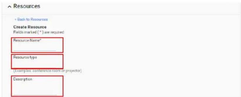
text_image
Resources Back to Resources Create Resource Fields marked (*) are required Resource Name* Resource type (Examples: conference room or projector) DescriptionFIG. 161 Google Admin Console - Calendar Page - Resources Pane (Create a new resource)
- Save changes.
2) Share Resource Calendars With Administrator
- From the Resources list, select the resource just created and copy the resource email address (FIG. 162):
^ Resources
« Back to Resources
Edit Resource
Fields marked (*) are required
Resource Name\*
Shelby Room 100
Resource type
conference room
(Examples: conference room or projector)
Description
Shelby Conference Room
100
Email address
eng.googl.amxservice.com_31333139313139323937@resource.calendar.google.com
Use this email address to access this resource in calendar.
All administrators can manage this resource by signing in to their own calendars.
FIG. 162 Google Admin Console - Calendar Page - Resources Pane (Copy new resource email address)
- In the Google toolbar, select the Apps icon (FIG. 163):

text_image
> Google Apps > Settings for CalendarFIG. 163 Google Admin Console Toolbar - Apps Icon
- In the Apps window, select the Calendar app (FIG. 164):
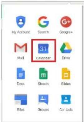
text_image
My Account Search Google+ Mail 31 Calendar Drive Docs Sheets Slides Sites Groups ContactsFIG. 164 Google Apps - Calendar
- In the Calendar, share the new resource calendar by selecting Add a Coworkers Calendar under Other Calendars (FIG. 165):
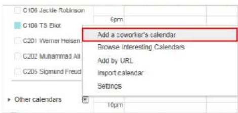
text_image
C100 Jackie Robinson C100 TS Eliot C201 Werner Heisen C202 Muhammad Ali C205 Sigmund Freud Other calendars 6pm Add a coworker's calendar Browse Interesting Calendars Add by URL Import calendar Settings 10pmFIG. 165 Google Calendar - Other Calendars > Add a Coworkers Calendar
- In the Add Coworkers Calendar window, paste the email address for the resource (in the Contact Email field) and select Add (FIG. 166):

text_image
Add a coworker's calendar Contact Email: 937333739@resource.calendar.google.com × Add Enter the email address of another person to view their calendar. Not all of your contacts will have calendar information that is shared with you, but you can invite them to create a Google Calendar account, or share their calendar with you.FIG. 166 Add a Coworkers Calendar - Contact Email
- The resource calendar should now show up in the list of calendars under My Calendars (see "Room 101" in FIG. 167):
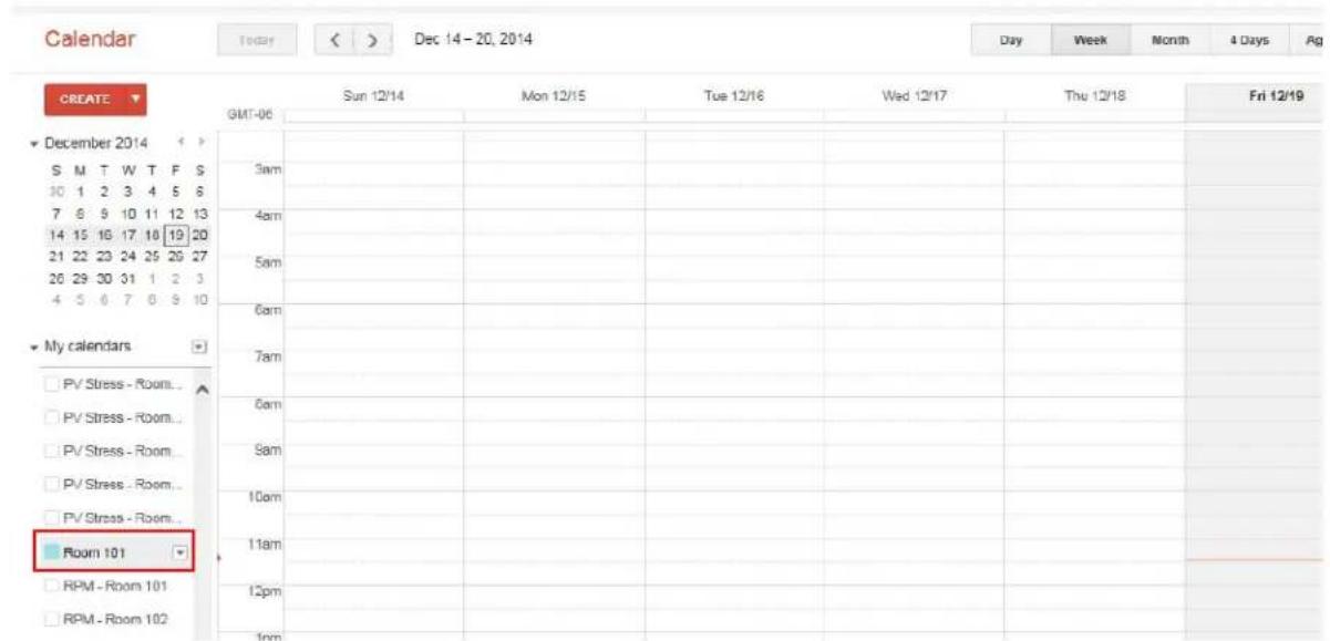
text_image
Calendar Today < > Dec 14 - 20, 2014 Day Week Month 4 Days Ag CREATE ▼ GMT-06 Sun 12/14 Mon 12/15 Tue 12/16 Wed 12/17 Thu 12/18 Fri 12/19 December 2014 S M T W T F S 10 1 2 3 4 5 6 7 6 9 10 11 12 13 14 15 16 17 18 19 20 21 22 23 24 25 26 27 26 29 30 31 1 2 3 4 5 6 7 8 9 10 My calendars □ PV Stress - Room... □ PV Stress - Room... □ PV Stress - Room... □ PV Stress - Room... □ PV Stress - Room... □ Room 101 □ RPM - Room 101 □ RPM - Room 102FIG. 167 Google Calendar Indicating new Calendar ("Rom 101")
3) Share Service Calendars With Room Manager Account
- Share the room administrator account with the resource calendar by selecting Share this Calendar for the resource calendar in the My Calendars list (FIG. 168):

text_image
Display only this Calendar Hide this calendar from the list Calendar settings Create event on this calendar Share this Calendar Edit notifications Choose custom colorFIG. 168 Share This Calendar
- In the Room Details - Share This Calendar page, paste the Room Manager account email address in the Person field (FIG. 169):
Share with specific people

text_image
person 333@developer.gserviceaccount.com "Room 101"FIG. 169 Google Calendar > Room Details > Share This Calendar > Share With Specific People > Person
- Under Permission Settings, select Make changes AND manage sharing (FIG. 170):

text_image
Permission Settings Make changes AND manage sharing Add Person Make changes AND manage sharingFIG. 170 Google Calendar > Room Details > Share This Calendar > Permission Settings
- Select Add Person (FIG. 171):

Make changes AND manage sharing
FIG. 171 Google Calendar > Room Details > Share This Calendar > Permission Settings > Add Person
- Click Save. At this point, Google will prompt you to verify these changes. Select OK to proceed (FIG. 172):
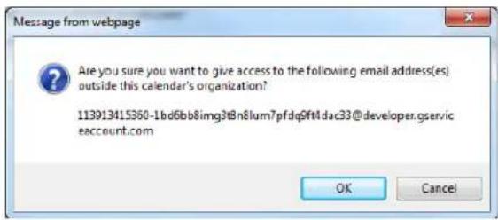
text_image
Message from webpage Are you sure you want to give access to the following email address(es) outside this calendar's organization? 113913415360-1bd6bb8img3@n8lum7pfdq9fMdac33@developer.gserviceaccount.com OK CancelFIG. 172 Google Calendar - Message From Webpage
4) Ensure Calendar Is Set To Deny Conflicts
- Right-click on the new calendar resource, and select Calendar Settings (FIG. 173):
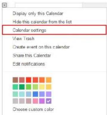
text_image
Display only this Calendar Hide this calendar from the list Calendar settings View Trash Create event on this calendar Share this Calendar Edit notifications Choose custom colorFIG. 173 Google Calendar - Calendar Settings option
- In the Calendar Details page - Auto-accept invitations section, verify that Auto-accept invitations that do not conflict is selected (FIG. 174):
Auto-accept invitations
Calendars for resources like conference rooms can automatically accept invitations from people with whom the calendar is shared when there are no conflicting events. Learn more
● Auto-accept invitations that do not conflict.
- Automatically add all invitations to this calendar.
- Do not show invitations.
FIG. 174 Calendar Details page > Auto-accept invitations > Auto-accept invitations that do not conflict
- Save changes.