LOH60 - Range hood LYNX - Free user manual and instructions
Find the device manual for free LOH60 LYNX in PDF.

User questions about LOH60 LYNX
0 question about this device. Answer the ones you know or ask your own.
Ask a new question about this device
Download the instructions for your Range hood in PDF format for free! Find your manual LOH60 - LYNX and take your electronic device back in hand. On this page are published all the documents necessary for the use of your device. LOH60 by LYNX.
USER MANUAL LOH60 LYNX
IMPORTANT SAFETY INSTRUCTIONS
PLEASE READ ENTIRE INSTRUCTION BEFORE PROCEEDING. INSTALLATIONS MUST COMPLY WITH ALL LOCAL CODES.
IMPORTANT: Save these Instructions for the Local Electrical Inspector's use.
INSTALLER: Please leave these Installation Instructions with this unit for owner.
OWNER: Please retain these Instructions for future reference
WARNING - TO REDUCE THE RISK OF FIRE, ELECTRICAL SHOCK, OR INJURY TO PERSONS, HOODS SHOULD BE INSTALLED WITH VENTILATORS APPROVED FOR USE WITH THE HOOD. SEE TABLE – 1 ON THIS PAGE FOR APPROVED VENTILATORS.
WARNING - TO REDUCE THE RISK OF FIRE, ELECTRIC SHOCK, OR INJURY TO PERSONS, OBSERVE THE FOLLOWING:
A. Installation work and Electrical Wiring Must Be Done By Qualified Person(s) In Accordance With All Applicable Codes & Standards. Including Fire-Rated Construction. "WARNING" To Reduce The Risk Of Fire, Use Only Metal Duct Work.
B. Sufficient air is needed for proper combustion and exhausting of gases
through the flue (chimney) of fuel burning equipment to prevent backdrafting. Follow the heating equipment manufactures guideline and safety standard such as those published by the National Fire Protection Association (NFPA) and the American Society for Heating, Refrigeration and Air Conditioning Engineers (ASHRAE), and the local code authorities.
C. When cutting or drilling into wall or ceiling, do not damage electrical wiring and other hidden utilities.
D. Ducted fans must always be vented to the outdoors.
E. Before Servicing or Cleaning Unit, Switch Power off At Service Panel And Lock Service Disconnecting Means to Prevent Power From Being Switched On Accidentally. When The Service Disconnecting Means Cannot be Locked, securely Fasten A Prominent Warning Device, Such As A Tag, To The Service Panel
CAUTION - TO REDUCE THE RISK OF FIRE AND TO PROPERLY EXHAUST AIR, BE SURE TO DUCT AIR OUTSIDE FOR DUCTED FANS – DO NOT VENT EXHAUST AIR INTO SPACE WITHIN WALLS OR CEILING OR INTO ATTICS, CRAWL SPACES OR GARAGES.
Read this instruction completely before starting installation. Planning the complete installation before starting any work is highly recommended. This includes all aspects of the installation including hood location, ducting, electrical requirements, and adequacy of mounting surfaces.
TABLE - 1 Model LOHI = Internal ventilator Model LOHE = Remote ventilator
This hood series has been designed to be used with the ventilators shown in Table - 1. Before cutting into cabinets, it is necessary to confirm that the correct ventilator is being used. Your dealer should have reviewed your needs prior to your purchase. Be sure you have the correct ventilation system.
CAUTION: To Reduce The Risk Of Fire And Electrical Shock, Install This Rangehood Only With Blowers Manufactured By Lynx Professional Grills.
DUCTING: Use a minimum 10" round duct for LOHI and LOHE installations. See Page - 3. A standard starting transition (33895) is included with the Hood.
SAFTY WARNING:
Turn off power circuit at the service entrance and lockout panel before wiring the range hood.

NOTE: Unit must be vented
to the outside of the building.
BEFORE STARTING INSTALLATION, YOU MUST IDENTIFY THE VENTILATOR MODEL BEING USED AND IF A TOP OR REAR EXHAUST IS TO BE USED.
Prepare cabinet and/or wall for mounting either top (Fig - 1) or rear (Fig 6 & 7) exhaust. Use furring strips to level cabinet mounting surface with any cabinet trims.
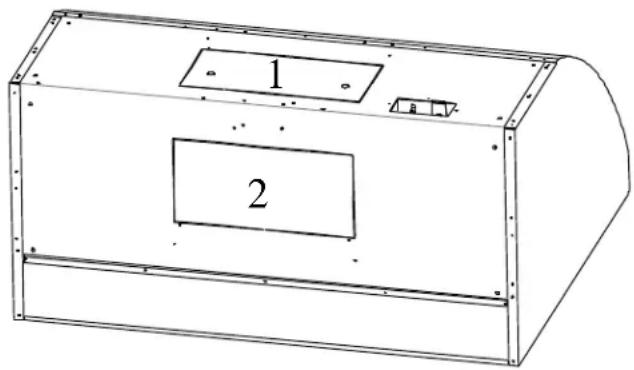
For knock out removal see Fig-B
| Remove | See | ||
| Ventilator Model | Knock out # | Transition# | Fig |
| LOHI Top Exhaust | 1 | 33895 | 1,2,3 |
| LOHE Top Exhaust | 1 | 33895 | 1,2,3 |
| LOHI Rear Exhaust | 2 | 33895 | 4,5,6,7 |
| LOHE Rear Exhaust | 2 | 33895 | 5,6,7 |
Break the metal webs by placing a screwdriver at one corner of the plate and hitting screwdriver sharply with a hammer. After breaking a second web the plate can be flexed to break other webs.
Wear eye protection when using tools.
Caution: When knock outs are removed the edges will be sharp! Sharp Edges should be Filed or Covered with Metal Tape.
Attach and secure the transition to the hood with #6x3/8 sheet metal screws and tape all joints prior to installing the hood. Attach hood to cabinet using #10 wood screws. Holes are located in the back panel and top panel of the hood for mounting. Use a minimum of four #10x3/4 wood screws to mount the hood. Longer screws are required if wall board or other nonstructural surfaces are used between the hood and main mounting surface which should be a minimum of 3/4" thick. When using rear holes for additional mounting use appropriate anchors if not engaging the wood structure. HINT: If you find vibration noise is present because of cabinet structure use additional screws, in holes available, to make the mounting more ridged.
Connect 120 volt, 60 Hz power through the conduit hole in top of hood, connecting to pigtail in hood junction box, white to white, black to black and connect green ground wire to the power supply ground wire per local codes. See Fig – A.
NOTE: Recommended height over BBQ Grills = 36 inches.
Hood is recommended for use over domestic gas or electric appliances. Not recommended for use over solid fuel fired appliances.
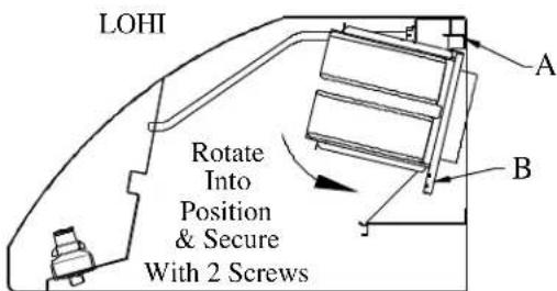
After installing the hood, install the internal blower (Top Exhaust See Fig 2; Rear Exhaust See Fig - 4) unit by positioning the blower onto bracket-A, notched blower bracket will center blower. Rotate into position against hood and secure Bracket – B to Hood with #8 sheet metal screws. If the remote ventilator is used see related instructions. The
LOHE ventilator will require revision of some wiring in the hood receptacle box - See LOHE instructions.
NOTE: LOHE requires a dedicated 20 AMP Power Supply. All other ventilators require a dedicated 15 AMP Power Supply
CAUTION: The hood is of sufficient weight that two installers are recommended to prevent injury or damage to the hood in handling.
Turn the power on at the service entrance and check the operation of the controls.
NOTE: be sure that all dampers are operating properly and are free to open.
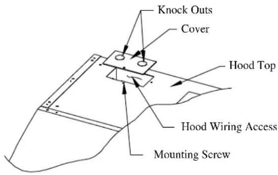
RECEPTACLE BOX COVER
text_image
Knock Outs Cover Hood Top Hood Wiring Access Mounting ScrewRemove Appropriate Knock Outs and Connect Wiring According to Hood and Blower Installation Instructions. CAUTION: Always Install Receptacle Box Cover.
Fig-A
natural_image
Technical line drawing of a rectangular mechanical housing or enclosure with labeled components (no text or symbols beyond labels)Fig - B
| FIG-1 | HOOD MODELS LOHI TOP EXHAUST | Hood Width | Dim "A" | ||
| 36" | 10-3/8 | ||||
| 48" | 14-3/8 | ||||
| 60" | 20-3/8 | ||||
 | |||||
| FIG-2 | Secure Transition To Hood Using #6 X 3/8" Sheet Metal Screws. Tape All Joint & Seams | Vertical Discharge | FIG - 3 | ||
| Remc | Use # 33895 Transition To 10" Duct |  | |||
 | The 10" Discharge With Transition Will Be On The Center Line Of Hood Width And On Center Line of 12" Dimension. | ||||
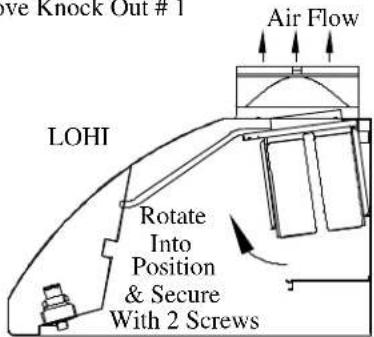
FIG - 4
Remove Knock Out # 2
text_image
LOHI Rotate Into Position & Secure With 2 Screws A BHOOD MODELS LOHI REAR EXHAUST
FIG - 6
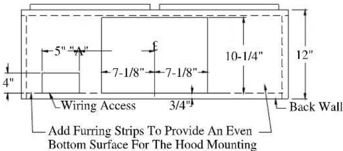
Bottom View Of Cabinet
Internal Or Remote Blowers
text_image
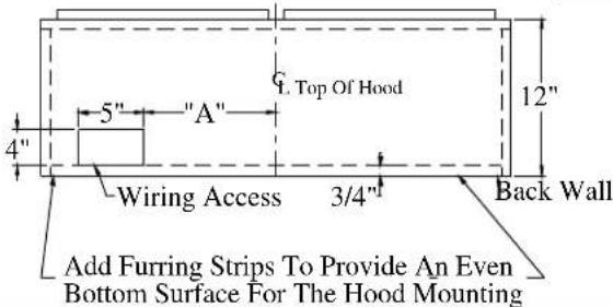
Top Of Hood 12" 5" "A" 4" Wiring Access 3/4" Back Wall Add Furring Strips To Provide An Even Bottom Surface For The Hood Mounting| Hood Width | Dim "A" |
| 36" | 10-3/8 |
| 48" | 14-3/8 |
| 60" | 20-3/8 |
FIG - 5
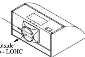
Use # 33895 Transition To 10" Duct Or Wall Cap
text_image
outside - LOHCRoute To Outside
W/Wall Cap - LOHC
Secure Transition To Hood Using #6 x 3/8" Sheet Metal Screws. Tape All Joints And Seams.
FIG - 7

text_image
FIG - 7 Rear Exhaust 14-1/2" Top Of Hood 1-3/4" 7-1/4" 7-1/8" 10-1/2" C Of Hood Width Of Hood Cut Hole In DrywaⒶ Center Of Round Duct Using Transition
To Accept Transition # 33895
Outside Patio or Lanai Installation
Construction methods and installation shall comply with all local building codes. Internal ducting shall be sealed using outdoor rated metal duct tape.
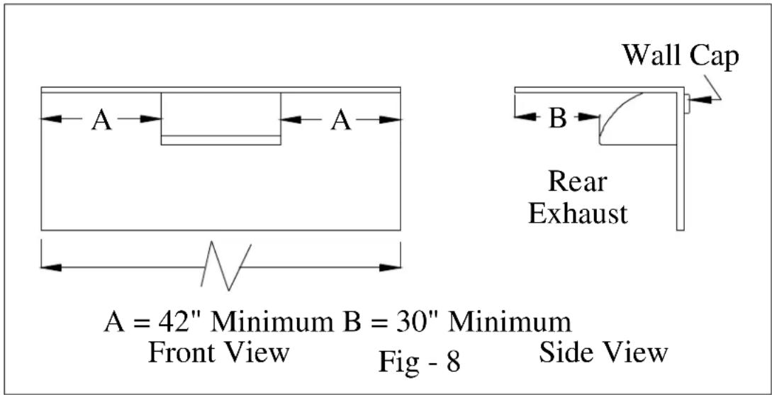
The LYNX hood with stainless steel canopy is approved for installation in an outside patio or lanai area if the area is covered with a protective roof over the hood (wall style hoods are to be also mounted to a solid protective rear wall) and installed with a GFCI protected branch circuit. Roof or Wall Caps are to be sealed to prevent moisture migration to structure interior; use an outdoor rated sealant suitable for adhesion to the installation materials. See Fig-8 for rear exhaust installation and Fig-9 for top exhaust installation.
text_image
A = 42" Minimum B = 30" Minimum Front View Fig - 8 Side View Wall Cap B Rear ExhaustSee Fig - 10 for structure with elevated roof/ceiling.
text_image
SUITABLE FOR USE IN DAMP LOCATIONS WHEN INSTALLED IN A GFCI PROTECTED BRANCH CIRCUITThe Roof shall cover the top of the hood and extend a minimum of 42" from each side of the hood and 30" minimum from the outer most edges of the hood front.
Since, outdoor areas are subject to strong cross drafts it is recommended that the hood extend at least 3 – inches, and preferably 6 – inches, over either side of the cooking area to maximize the cooking discharge capture area. Cross drafts will affect the efficiency of the ventilation system and cooking discharge can escape capture by the hood/ventilation system. Be sure to plan for adequate ventilator (blower) capacity to minimize cross drafts influencing the removal of cooking discharges.
The installation instruction that accompanies the hood shall be followed to ensure all safety Instructions and guidelines are adhered to. NOTE: Hood is recommended for use over domestic gas or electric appliances. Not recommended for use over solid fuel fired appliances. See Fig-10 for soffit construction
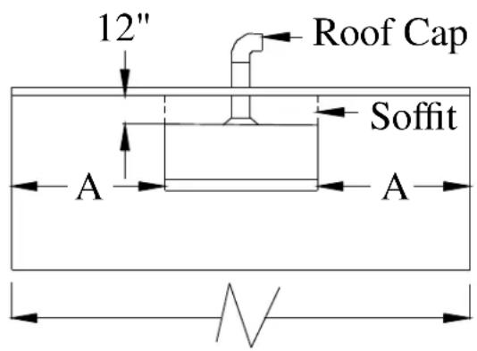
text_image
12" Roof Cap Soffit A AFront View

text_image
B Top Exhaust$$ \begin{array}{c} \mathrm{B} = 3 0 ^ {\prime \prime} \text {MinimumA} = 4 2 ^ {\prime \prime} \text {Minimu} \ \text {Side View} \end{array} $$
Fig - 9
See Fig - 10 for structure with elevated roof/ceiling.
For installations with elevated Roof/Ceiling use a Soffit, or optional stainless steel extension
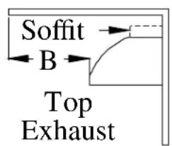
text_image
Soffit B Top Exhaust$$ \begin{array}{c} \mathrm{B=30"Minimum} \ \text {Side View} \end{array} $$
Constructed Soffit

text_image
4" MIN Hood Widths 12"$$ \begin{array}{l} \text {Soffit Top, Sides} \ \& \text {Front Shall Be} \ \text {Enclosed. Fasten} \ \text {To Top Of Hood} \end{array} $$
Stainless Canopy Extension
Canopy - Extension
Fasten To Top Of Hood

text_image
n o TopFasten Wall Board Panel To Underside Of Top Flange
Fig - 10
Soffit shall be constructed of materials suitable for outdoor installation and be sealed to prevent moisture migration to structure interior.
NOTE: 4-1/4" Tall Starting Transition is Included with the Hood.
Transition dimensions may very. Before assembling transitions to hood, fit them into the prepared cabinet opening to be sure the openings are large enough to accommodate the transition. Enlarge the hole if required
Attach the transition (See DUCTING, pg 1), supplied with hood as described previously in this instruction.

text_image
4-1/4" 14-1/4" 10-3/8"Transition # 33895
INSTALLATION and USE & CARE INSTRUCTIONS BAFFLE FILTER KIT
INSTALLER: Please leave these Installation Instructions with unit for the owner.
- You are now ready to install the baffle filters. Remove all packaging and the protective plastic covering from the filters.
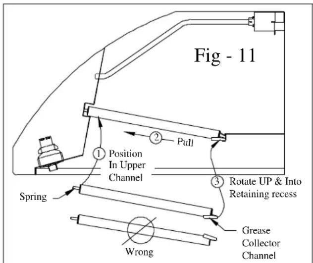
- Grasp the filter by the center baffle, see FIG-11, with the spring end facing you and the grease collector channel facing down and toward the rear of the hood. Position the spring end of the filter into the upper channel of the front escutcheon, compress the spring by pulling the filter toward you and rotate the rear of the filter up and into the rear retaining recess formed by the rear escutcheon and retaining clip. Release the filter, being sure it is positioned properly in the channels. You should be able to push up and pull down on the filter without having it come out of position. You can bend the spring slightly outward if the filter is not pressing securely against the rear escutcheon.
- The filter has an integral grease collector and is dishwasher safe. To clean your filter simply grasp the filter by its center baffle, pull toward the front of the hood and rotate the rear of the filter down and away from the hood, see FIG-12.
- For best dishwasher results, position the filters in the dishwasher rack with the baffles positioned horizontally.
text_image
Fig - 11 Position In Upper Channel Pull Spring Wrong Grease Collector Channel Rotate UP & Into Retaining recess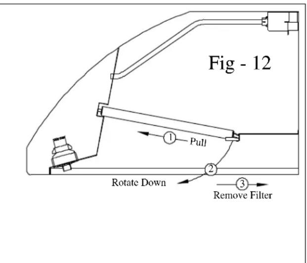
text_image
Fig - 12 ① Pull ② Rotate Down ③ Remove Filter
flowchart
graph TD
    A["POWER SUPPLY"] --> B["HOOD RECEPTACLE BOX"]
    B --> C["BLOWER MOTOR INTERNAL"]
    C --> D["LOHI"]
    E["MODELS WITH (4) LIGHT"] --> F["LEFT LIGHT"]
    F --> G["LIGHT SWITCH"]
    G --> H["3-SPD ROTARY SWITCH"]
    H --> I["RIGHT LIGHT"]
    J["MODELS WITH (4) LIGHT"] --> K["3-SPD ROTARY SWITCH"]
    K --> L["RIGHT LIGHT"]
    M["18 W #5B"] --> N["18 B #6"]
    N --> O["18 B #7A"]
    O --> P["18 W #9A"]
    P --> Q["18 W #15"]
    Q --> R["18 W #13"]
    R --> S["18 W #12"]
    S --> T["18 G #11"]
    T --> U["18 W #25"]
    U --> V["1 1"]
    V --> W["18 White"]
    V --> X["18 Black"]
    V --> Y["18 Blue"]
    V --> Z["18 Red"]
    H --> AA["A 1"]
    H --> AB["B 2"]
    H --> AC["3"]
    H --> AD["4"]
    H --> AE["18 BL #23"]
    H --> AF["18 BL #24"]
    H --> AG["18 BL #25"]
Page 7 of 8 P/N 11857.00 Rev A
Lynx Professional Grills
6023 E. Bandini Blvd.
Commerce, CA 90040
Service: (888) Buy-Lynx
(888-289-5969)
www.lynxgrills.com
Fax: (323) 838-1778
IMPORTANT SAFETY INSTRUCTIONS:
READ ENTIRE INSTRUCTIONS BEFORE PROCEEDING. Installation must comply with all applicable codes. READ AND SAVE THESE INSTRUCTIONS
IMPORTANT: Save for local electrical inspector's use.
INSTALLER: Please leave these instructions with this unit for the owner.
OWNER: Please retain these instructions for future use.
WARNING – TO REDUCE THE RISK OF FIRE, ELECTRIC SHOCK, OR INJURY TO PERSONS, OBSERVE THE FOLLOWING:
a) Use this unit only in the manner intended by the manufacturer. If you have questions, contact the manufacturer.
b) Before servicing or cleaning unit, switch power off at service panel and lock the service disconnecting means to prevent power from being switched on accidentally. When the service disconnecting means cannot be locked, securely fasten a prominent warning device, such as a tag, to the service panel.
WARNING: TO REDUCE THE RISK OF FIRE, USE ONLY METAL DUCTWORK.
WARNING - TO REDUCE THE RISK OF FIRE, ELECTRIC SHOCK, OR INJURY TO PERSONS, OBSERVE THE FOLLOWING:
a) Installation work and electrical wiring must be done by qualified person(s) in accordance with all applicable codes and standards, including fire-rated construction.
b) Sufficient air is needed for proper combustion and exhausting of gases through the flue (chimney) of fuel burning equipment to prevent back drafting. Follow the heating equipment manufacturer's guideline and safety standards such as those published by the National Fire Protection Association (NFPA), and the American Society for Heating, Refrigeration and Air Conditioning Engineers (ASHRAE), and the local code authorities.
c) When cutting or drilling into wall or ceiling, do not damage electrical wiring and other hidden utilities.
d) Ducted fans must always be vented to the outdoors.
WARNING - To Reduce The Risk Of Fire Or Electric Shock, Do Not Use This Fan With Any Solid-State Speed Control Device
CAUTION: To reduce the risk of fire and to properly exhaust air, be sure to exhaust air outside. Do not exhaust air into spaces within walls or ceiling or into attics, crawl spaces or garages.
CAUTION – For General Ventilating Use Only. Do Not Use To Exhaust Hazardous Or Explosive Materials And Vapors.
NOTE: THESE INSTRUCTIONS DESCRIBE THE INSTALLATION OF THE LOHE REMOTE VENTILATOR WITH A LYNX HOOD. IF USED WITH ANOTHER MANUFACTURER'S HOOD, REFER TO THEIR SPECIFICATIONS FOR POWER REQUIREMENT COMPATABILITY.
LOHE: 1-HP 3-SPEED MOTOR, 115V AC, 60Hz /20 Amp CIRCUIT REQUIRED
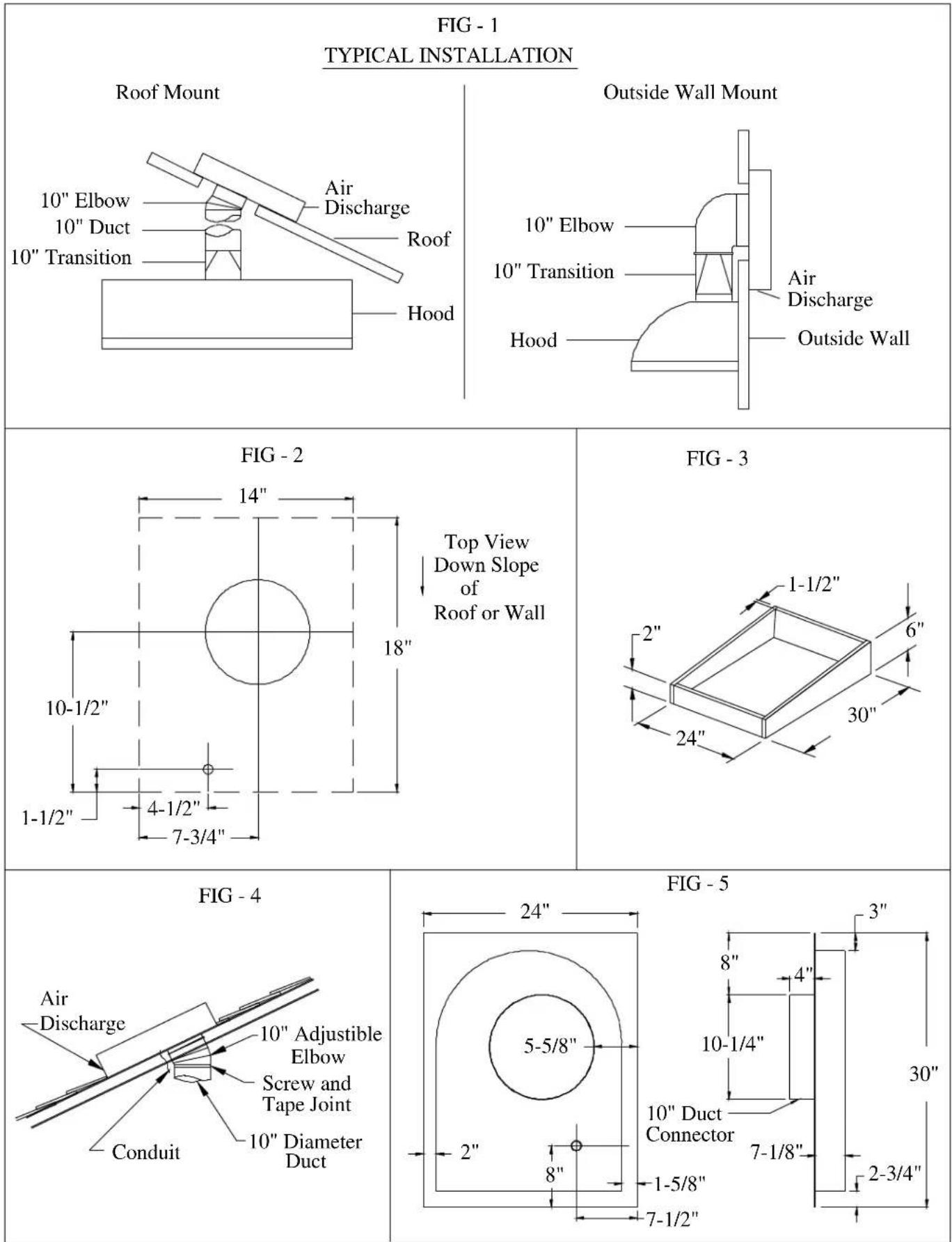
- Provide square hole through the roof or wall as shown by dash lines for conduit as shown in Fig-2. For reference, location of 10" duct connection and wiring connection is shown with solid lines.
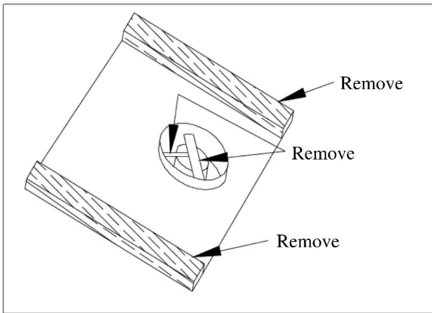
- Remove shipping bracket per separate instruction. SEE PAGE - 2
- Install ventilator on roof or wall, with discharge (screened end) pointing down, according to STANDARD ROOFING PROCEDURES. Note: Front discharge edge should be on top of shingles and rear and side edges under shingles. Note: Unit must be sealed between roof or wall and underside of flange with roofing mastic to prevent leaks. For installation on a flat roof, or roofs with pitch of less than 1-1/2" in 12", install ventilator on curb as shown in Fig-3. Position curb on sloping roof with 2" dimension facing down slope. Position curb on flat roofs so that discharge (screened end) points away from prevailing wind.
- Connect the ventilator to exhaust system with a 10" diameter metal duct only. Use 10" adjustable elbow to adjust to roof angle. Tape and screw all joints to prevent air leaks. See Fig-4.
- Remove top cover of ventilator to access wiring connections. Retain mounting screws.
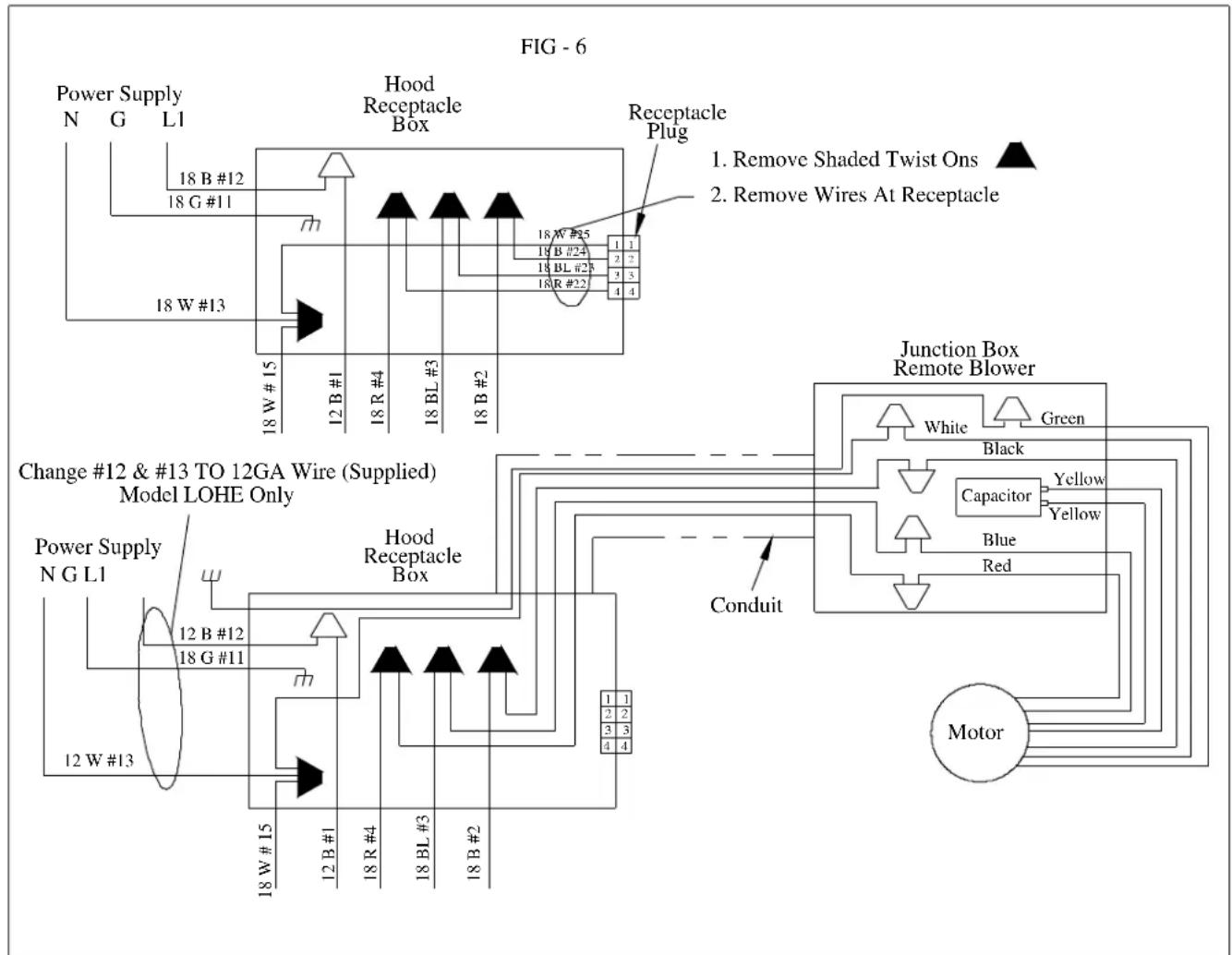
- Run electrical conduit per local code to conduit outlet in bottom plate of ventilator (use liquid tight connection). Other end of conduit will connect to electrical box in your LYNX hood. See hood installation instructions for hood wiring location. See Fig - 6.
- Run four (4) 16 ga wires in conduit (1-black, 1-white, 1-blue and 1-red) between the ventilator and hood. Check for local code compliance. The ground wire should be 16 ga wire. See Fig-6 for wiring details. Check for local code compliance.
- Dimensions of ventilator are shown in Fig-5.
- When connecting the hood to power supply, replace the black-#12 wire and white-#13 wire on hood with the wires supplied with the remote blower. Power supply for the LOHE plus hood requires a 120v, 20 amp, 60 Hz circuit, connected per local codes.
- Rotate ventilator blower wheel to be sure it turns freely and does not rub on motor brackets. Check damper door to be sure it moves freely and spring returns door to closed position.
- Check screen guard to be sure it is in position and secure. Check for removal of shipping bracket.
- Replace cover removed in Step-4 and secure with screws provided. All screws must be in place on cover.
- See Fig-1 for typical hood installations.
ATTENTION INSTALLER
text_image
Remove Remove Remove**********************************************************************
Attention Installer Remove Shipping Bracket And Wood Supports Before Installing
**********************************************************************
flowchart
graph TD
    A["Power Supply N G L1"] --> B["18 B #12"]
    A --> C["18 G #11"]
    A --> D["18 W #13"]
    B --> E["Hood Receptacle Box"]
    C --> E
    D --> E
    E --> F["Receptacle Plug"]
    F --> G["18 W #25"]
    F --> H["18 BL #23"]
    F --> I["18 R #22"]
    G --> J["1 1"]
    H --> K["2 2"]
    I --> L["3 3"]
    J --> M["18 W #15"]
    K --> N["12 B #1"]
    L --> O["18 R #4"]
    M --> P["18 BL #3"]
    N --> Q["18 B #2"]
    O --> R["18 W #15"]
    P --> S["18 BL #3"]
    Q --> T["18 W #15"]
    R --> U["12 B #1"]
    S --> V["18 BL #3"]
    T --> W["18 B #2"]
    U --> X["Change #12 & #13 TO 12GA Wire (Supplied) Model LOHE Only"]
    V --> X
    W --> X
    X --> Y["Hood Receptacle Box"]
    Y --> Z["Conduit"]
    Z --> AA["Junction Box Remote Blower"]
    AA --> AB["White"]
    AA --> AC["Green"]
    AA --> AD["Black"]
    AA --> AE["Capacitor"]
    AA --> AF["Yellow"]
    AA --> AG["Blue Red"]
    AA --> AH["Motor"]
A. Access the hood junction box, remove the designated twist on connectors.
B. Access the remote blower wiring box by removing the top cover, set aside screws for later use.
C. Run four wires per local code, in conduit from remote blower to hood.
NOTE: maintain white, black, blue and red color code from blower wiring box to hood connections.
D. Connect 4-wire from blower to hood with twist-on connectors from step – A; remote white to #13 & 15, remote black to #24 black, remote blue to #23 blue and remote red to #22 red.
NOTE: When connecting the hood to power supply, replace the black #12 wire and white #13 wire on hood with the 12 ga. wires supplied with the ventilator. See Fig - 6.
When remote blower is to be grounded to the Power Supply Main Ground use appropriate wire gage per local codes. See Fig - 6.
If the blower is grounded through the Hood the 16 ga Green Pigtail wire at the hood Must Be Changed to 12 Ga, or Appropriate Wire Gage to Comply With Local Codes.
CAUTION: To prevent malfunction and/or harm to electrical components, connections are to be made per diagram and instructions.
E. Check rotation of blower wheel to be sure it rotates freely and does not rub brackets.
F. Replace blower top cover and screws from step - B.
Lynx Professional Grills
6023 E. Bandini Blvd.
Commerce, CA 90040
Service: (888) Buy-Lynx
(888-289-5969)
www.lynxgrills.com
Fax: (323) 838-1778
CAUTION: Before installing ventilator read the HOOD INSTALLATION INSTRUCTIONS.
PARTS INCLUDED: 1 - Ventilator Assembly
4 - #8 x 1/2 Pan Head SMS
1 - Wire Harness (#33896)
1 - Wire Tie

natural_image
Technical line drawing of a mechanical component with cylindrical and rectangular parts, labeled A (no text or symbols present)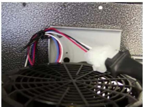
natural_image
Close-up of a white electronic device with black wires and a mesh fan, placed on a textured wall (no visible text or symbols)1) Install Hood & Transition per hood installation instruction.
2) Remove parts from carton. Remove all corrugated packaging shims between motor and housing.
3) Rotate ventilator wheels to confirm they rotate freely.
4) Connect Wire Harness #33896 to Hood Receptacle Box.
5) Install ventilator per HOOD INSTALLATION INSTRUCTION using 2-screws.
6) Connect Ventilator to Hood Receptacle Plug on Front Panel using Wire Harness #33896, (if required excessive wires shall be attached to blower body flange notch at point - A using wire tie, twist wire 3 to 4 times to secure excess wire – see picture).
7) Check operation of ventilator per HOOD INSTALLATION INSTRUCTIONS.

flowchart
graph LR
    subgraph WIRING_LOHI
        MOTOR1["MOTOR"] --> GND
        GND --> GREY1["GREY"]
        GREY1 --> IC1["IC"]
        IC1 --> BLACK1["BLACK"]
        GREEN1["GREEN"] --> GND
        GND --> WHITE1["WHITE"]
        WHITE1 --> RED1["RED"]
        RED1 --> BLFE1["BLUE"]
        BLFE1 --> YELLOW1["YELLOW"]
        YELLOW1 --> RED2["RED"]
        RED2 --> BLFE2["BLUE"]
        BLFE2 --> YELLOW2["YELLOW - LO"]
        YELLOW2 --> RED3["RED - MED"]
        RED3 --> BLUE3["BLUE - HI"]
        BLUE3 --> WHITE3["WHITE - COM"]
        BODY1["BODY"] --> GND
        GND --> GREEN2["GREEN"]
        GREEN2 --> GND
        GREEN2 --> WHITE2["WHITE"]
        WHITE2 --> RED4["RED"]
        RED4 --> BLFE4["BLUE"]
        BLFE4 --> YELLOW4["YELLOW - LO"]
        YELLOW4 --> RED5["RED - MED"]
        RED5 --> BLUE5["BLUE - HI"]
        BLUE5 --> WHITE5["WHITE - COM"]
    end

    subgraph WIRE HARNESS_P/N 33896
        MOTOR2["MOTOR"] --> GND
        MOTOR2 --> GREY2["GREY"]
        GREY2 --> IC3["IC"]
        IC3 --> BLACK2["BLACK"]
        BLACK2 --> RED6["RED"]
        RED6 --> BLFE6["BLUE"]
        BLFE6 --> YELLOW6["YELLOW - LO"]
        YELLOW6 --> RED7["RED - MED"]
        RED7 --> BLUE7["BLUE - HI"]
        BLUE7 --> WHITE7["WHITE - COM"]
        TOHOOD["TO HOOD RECEPTACLE PLUG"] --> BLFE7["BLFE"]
        BLFE7 --> RED8["RED"]
        RED8 --> BLFE8["BLUE"]
        RED8 --> YELLOW8["YELLOW - LO"]
        YELLOW8 --> RED9["RED - MED"]
        RED9 --> BLUE9["BLUE - HI"]
        BLUE9 --> WHITE9["WHITE - COM"]
    end
Lynx Professional Grills
6023 E. Bandini Blvd.
Commerce, CA 90040
Service: (888) Buy-Lynx
(888-289-5969)
www.lynxgrills.com
Fax: (323) 838-1778
P/N 11863.00 Rev A
INSTALLER: Please leave these Installation Instructions with unit for the owner.
Do not force shutter into opening!, Do not open shutter by lifting individual blades!.
Do not install shutter leaning forward or backward!
- Shutter frame should be mounted level and squarely on outside wall. Care should be taken not to twist the shutter frame. Never cover shutter with siding or masonry work. Shutter should be mounted so it can be removed any time in case of damage.
- Shutter should operate as freely after installation as it did before.
- CAUTION: Shutter flaps must open in the direction of airflow.
- Caulking compound is recommended between shutter frame edges and the wall. If Siding is present it should be made to overlap Damper Flashing on top & sides.
- Clean and lubricate shutter at the same time that the fan is clean.
- Tape the joint with a high-grade duct tape or metal (preferred) tape.
- Check installation for proper fan operation – shutter flaps must Open with fan ON and Close with fan OFF.

text_image
OUTSIDE OF WALL SHUTTER MOUNTING SCREWS (NOT INCLUDED) DO NOT TIGHTEN MOUNTING SCREWS TOO TIGHT INSIDE OF WALL METAL DUCT 10" ROUND FITS INSIDE BIRD SCREEN DIRECTION OF AIR FLOW COLLAR WITH BIRD SCREENLynx Professional Grills 6023 E. Bandini Blvd.
Commerce, CA 90040
Service: (888) Buy-Lynx
(888)-289-5969
www.lynxgrills.com
Fax: (323) 838-1778
CAUTION: Read this instruction and your hood installation instruction before starting installation. Plan the complete installation before starting any work. This includes all aspects of the installation including hood location, ducting, electrical requirements and adequacy of mounting surfaces.
NOTE: The duct and electrical connection cutouts, when using a canopy extension, are to be per this instruction and not those described in the hood installation instruction.
- Prepare ceiling opening to accept duct and transition installation per Fig - 1.
Locate the 120 volt, 60 Hz power supply in the crosshatched area “A”. You can increase the total opening by the area, “A” which will allow access to the hood junction box from the space above the ceiling.
- To prepare the wall for hood mounting, locate the four (4) mounting holes (7/32 Dia.) in the hood back and layout the hole pattern on the wall.
Note: Use # 10 screws to fasten hood to wall framing or wall anchors and #10 screws if framing is not present. Do not screw into wallboard.
HINT: You can mount the canopy extension to the hood, position hood against wall/ceiling, and mark the mounting hole locations on the wall.
- Lay hood in its back surface, position canopy extension on the hood top and secure with six (6) #8- SMS provided, three (3) on each side. See Fig - 2.
- Install transition to top of hood per instructions supplied with same.
- Position hood, as prepared above, and secure with (4) #10 screws (see step-2).
- Complete the electrical connections, duct connections and install ventilator per hood installation instructions. Turn power on and check all operations.
Fig - 1
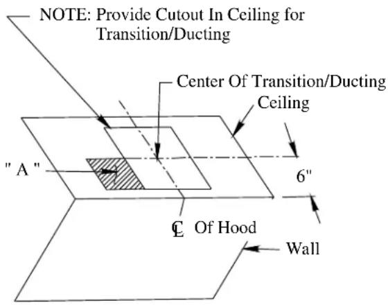
text_image
NOTE: Provide Cutout In Ceiling for Transition/Ducting Center Of Transition/Ducting Ceiling "A" 6" C Of Hood WallFig -2
