PowerEdge 5CJH1 - Server DELL - Free user manual and instructions
Find the device manual for free PowerEdge 5CJH1 DELL in PDF.

User questions about PowerEdge 5CJH1 DELL
0 question about this device. Answer the ones you know or ask your own.
Ask a new question about this device
Download the instructions for your Server in PDF format for free! Find your manual PowerEdge 5CJH1 - DELL and take your electronic device back in hand. On this page are published all the documents necessary for the use of your device. PowerEdge 5CJH1 by DELL.
USER MANUAL PowerEdge 5CJH1 DELL
Dell EMC PowerEdge T640
Installation and Service Manual
Notes, cautions, and warnings
NOTE: A NOTE indicates important information that helps you make better use of your product.
CAUTION: A CAUTION indicates either potential damage to hardware or loss of data and tells you how to avoid the problem.
WARNING: A WARNING indicates a potential for property damage, personal injury, or death.
© 2017 -2019 Dell Inc. or its subsidiaries. All rights reserved. Dell, EMC, and other trademarks are trademarks of Dell Inc. or its subsidiaries. Other trademarks may be trademarks of their respective owners.
2019 - 12
Rev. A09
Contents
1 Dell EMC PowerEdge T640 overview....8
Supported configurations....9
Front view of the system....10
Status LED indicators....12
iDRAC Direct LED indicator codes....13
iDRAC Quick Sync 2 indicator codes....13
System health and system ID indicator codes....14
Drive indicator codes....15
Back view of the system....16
NIC indicator codes....17
Power supply unit indicator codes....18
Locating the Service Tag of your system....19
System information label....20
2 Technical specifications....25
Chassis dimensions....25
Chassis weight....26
Processor specifications....26
Supported operating systems....26
Cooling fans....26
Cooling fan specifications....26
Removing a middle or rear cooling fan....27
Installing a middle or rear cooling fan....28
Removing the right external fan....29
Installing the right external fan....30
PSU specifications....31
System battery specifications.... 31
Expansion bus specifications.... 31
Memory specifications....32
Storage controller specifications....32
Drive specifications....33
Hard drives....33
Optical drive....33
Ports and connectors specifications....33
USB ports....33
NIC ports....33
VGA ports....33
Serial connector....34
Internal Dual SD Module with vFlash card....34
Video specifications....34
Environmental specifications.... 34
Standard operating temperature....35
Expanded operating temperature....35
Particulate and gaseous contamination specifications....36
3 Initial system setup and configuration....38
Setting up your system....38
iDRAC configuration....38
Options to set up iDRAC IP address....38
Log in to iDRAC....38
Options to install the operating system....39
Methods to download firmware and drivers....39
Downloading drivers and firmware....40
4 Pre-operating system management applications....41
Options to manage the pre-operating system applications....41
System Setup....41
Viewing System Setup....41
System Setup details....41
System BIOS....42
iDRAC Settings utility....61
Device Settings....62
Dell Lifecycle Controller....62
Embedded system management....62
Boot Manager....62
Viewing Boot Manager....62
Boot Manager main menu....62
One-shot UEFI boot menu....63
System Utilities....63
PXE boot....63
5 Installing and removing system components....64
Safety instructions....64
Before working inside your system....64
After working inside your system....64
Optional front bezel....64
Removing the front bezel....65
Installing the front bezel....65
System feet....66
Removing the system feet....66
Installing the system feet....67
Caster wheels – optional....68
Removing caster wheels....68
Installing caster wheels....69
Drives....70
Removing a drive blank....70
Installing a drive blank....71
Removing a drive carrier....72
Installing a drive carrier....72
Removing the drive from the drive carrier....73
Installing a drive into the drive carrier....74
Removing a 3.5 inch drive adapter from a 3.5 inch drive carrier....75
Installing a 3.5 inch drive adapter into the 3.5 inch drive carrier....76
Removing a 2.5 inch drive from a 3.5 inch drive adapter....76
Installing a 2.5 inch drive into a 3.5 inch drive adapter....77
Power supply units....78
PSU specifications....78
Hot spare feature....78
Removing a power supply unit blank....79
Installing a power supply unit blank....79
Removing a AC power supply unit....80
Installing a AC power supply unit....81
Removing a DC power supply unit....81
Installing DC power supply unit....82
Wiring instructions for a DC power supply unit....82
System cover 83
Removing the system cover....83
Installing the system cover 84
Inside the system....85
Air shroud....86
Removing the optional GPU air shrouds....86
Installing the optional GPU air shrouds....86
Removing the air shroud....87
Installing the air shroud....88
Cooling fans....89
Cooling fan specifications....89
Removing a middle or rear cooling fan....90
Installing a middle or rear cooling fan....91
Removing the right external fan....92
Installing the right external fan....93
Cooling fan (middle fan) assembly....94
Removing the middle cooling fan assembly 94
Installing the middle cooling fan assembly....94
Flex bays....95
Removing a NVMe drive bay or flex bay....95
Installing a NVMe drive bay or flex bay....96
Optical drives and tape drives....97
Optical drives and tape drives specifications....97
Removing the optical or tape drive blank....97
Installing the optical or tape drive blank....98
Removing the optical drive cage or tape drive....99
Installing the optical drive cage or tape drive....100
Removing the slim optical drive....101
Installing the slim optical drive....102
NVDIMM-N battery....103
Removing the NVDIMM-N battery....103
Installing the NVDIMM-N battery....104
System memory....104
System memory guidelines....104
General memory module installation guidelines....106
NVDIMM-N memory module installation guidelines .... 107
Mode-specific guidelines....108
Removing a memory module....110
Installing a memory module....111
Processors and heat sinks....112
Removing a processor and heat sink module....112
Removing the processor from the processor and heat sink module....113
Installing the processor into a processor and heat sink module.... 115
Installing a processor and heat sink module....117
Expansion card holder....119
Removing the expansion card holder....119
Installing the expansion card holder....119
GPU card holder (optional)....120
GPU card restriction....120
GPU card installation guidelines....120
Removing the optional GPU card holder....120
Installing the optional GPU card holder....121
Expansion cards....122
Expansion card installation guidelines....122
Expansion card slot priority....123
Removing a expansion card....124
Installing an expansion card....125
M.2 SSD module....126
Removing the M.2 SSD module....126
Installing the M.2 SSD module....127
Optional MicroSD or vFlash card....128
Removing the MicroSD card....128
Installing the MicroSD card....129
Optional IDSDM or vFlash module....130
Removing the optional IDSDM or vFlash module....130
Installing optional IDSDM or vFlash module....131
Backplane....132
Backplane connectors....132
Removing a backplane....134
Installing a backplane....135
Backplane cabling....136
Integrated storage controller card....139
Removing the integrated storage controller card....139
Installing the integrated storage controller card....139
System battery....140
Replacing the system battery....140
Optional internal USB memory key....141
Replacing the optional internal USB memory key....141
Control panel assembly....141
Removing the control panel assembly....141
Installing the control panel assembly....143
Trusted Platform Module....144
Upgrading the Trusted Platform Module....144
Initializing TPM for BitLocker users....145
Initializing the TPM 1.2 for TXT users....145
System board....145
Removing the system board....145
Installing the system board....147
Power interposer boards....149
Main and GPU power interposer boards connectors....150
Removing the GPU power interposer board....150
Installing the GPU power interposer board....151
Removing the main power interposer board....152
Installing the main power interposer board....152
Converting the system from tower mode to rack mode....153
Converting the system from tower mode to rack mode 153
6 System diagnostics....156
Dell Embedded System Diagnostics....156
Running the Embedded System Diagnostics from Boot Manager....156
Running the Embedded System Diagnostics from the Dell Lifecycle Controller....156
System diagnostic controls....157
7 Getting help.... 158
Contacting Dell EMC....158
Documentation feedback......158
Accessing system information by using QRL....158
Quick Resource Locator for PowerEdge T640....159
Receiving automated support with SupportAssist 159
Recycling or End-of-Life service information....159
Dell EMC PowerEdge T640 overview
The Dell EMC PowerEdge T640 is a dual-socket, 5U rackable tower server that supports up to:
- Two Intel Xeon Scalable processors
- 24 DIMM slots (support for DDR4 RDIMM, LR-DIMM) or 12 NVDIMM-N (one DIMM per channel) are supported
- Nine PCIe Gen 3 expansion cards, including a dedicated PERC slot
- Four GPUs
- Two hot swappable power supply units
- Drive configurations:
- 8 x 3.5-inch or 8 x 2.5 inch (in 3.5 inch carrier) SAS/SATA/SSD drives
- 18 x 3.5-inch SAS/SATA/SSD drives
- 16 x 2.5-inch SAS/SATA/SSD drives
- 16 x 2.5-inch SAS/SATA/SSD drives with 8 x NVME drives
- 32 x 2.5-inch SAS/SATA/SSD drives
Topics:
• Supported configurations
- Front view of the system
- Back view of the system
- Locating the Service Tag of your system
- System information label
Supported configurations
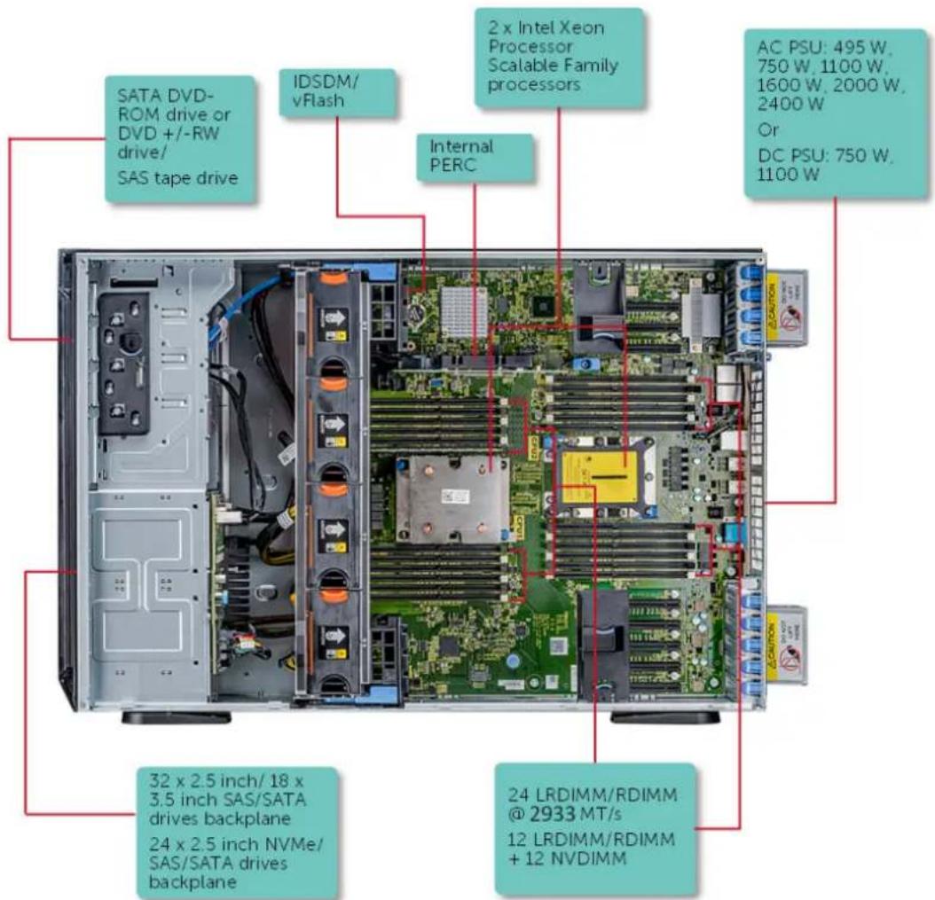
text_image
SATA DVD-ROM drive or DVD +/-RW drive/ SAS tape drive IDSDM/ vFlash 2 x Intel Xeon Processor Scalable Family processors Internal PERC AC PSU: 495 W, 750 W, 1100 W, 1600 W, 2000 W, 2400 W Or DC PSU: 750 W, 1100 W 32 x 2.5 inch/ 18 x 3.5 inch SAS/SATA drives backplane 24 x 2.5 inch NVMe/SAS/SATA drives backplane 24 LRDIMM/RDIMM @ 2933 MT/s 12 LRDIMM/RDIMM + 12 NVDIMMFigure 1. Supported configurations of the PowerEdge T640
Front view of the system
The front view displays the features available on the front of the system.
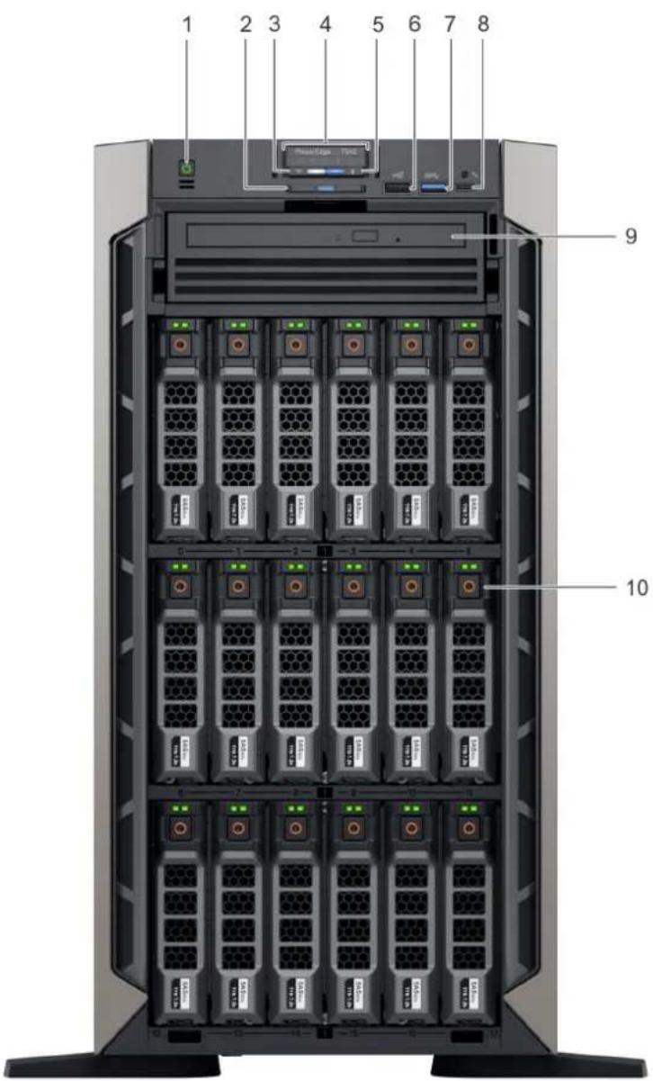
text_image
1 2 3 4 5 6 7 8 9 10Figure 2. Front view of the 18 x 3.5-inch drive tower system
- Power button 2. Information tag
- iDRAC Quick Sync 2 wireless indicator (optional) 4. Status LED indicators
- System health and system ID indicator 6. USB port (USB 2.0-compliant)
- USB port (USB 3.0-compliant) 8. iDRAC Direct (Micro-AB USB) port
- Optical drive (optional) 10. Drive slots
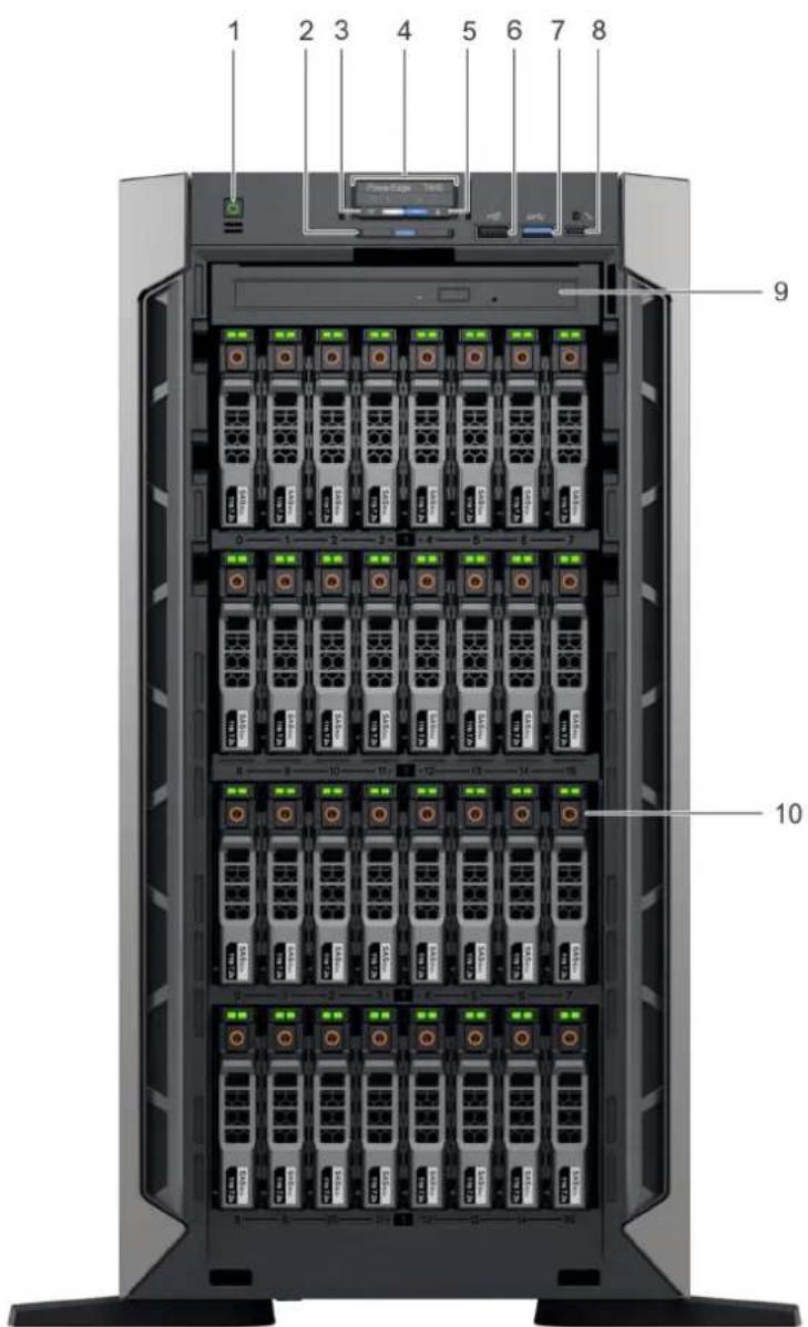
text_image
1 2 3 4 5 6 7 8 9 10Figure 3. Front view of the 32 x 2.5-inch drive tower system
- Power button 2. Information tag
- iDRAC Quick Sync 2 wireless indicator (optional) 4. Status LED indicators
- System health and system ID indicator 6. USB port (USB 2.0-compliant)
- USB port (USB 3.0-compliant) 8. iDRAC Direct (Micro-AB USB) port
- Optical drive (optional) 10. Drive slots

text_image
1 2 3 4 5 6 7 8 9 10 11 12 13Figure 4. Front view of the 8 x 3.5-inch drive rack system
- Power button 2. Information tag
- iDRAC Quick Sync 2 wireless indicator (optional) 4. Status LED indicators
- System health and system ID indicator 6. USB port (USB 2.0-compliant)
- VGA port 8. USB port (USB 3.0-compliant)
- iDRAC Direct (Micro-AB USB) port 10. Optical drive (optional)
- Drive slots 12. Rack ear latch (2)
- Drive blank
For more information on the ports, see the Technical specifications section.
Status LED indicators

NOTE: The indicators display solid amber if any error occurs.

natural_image
Five white icons on dark background: speech bubble, folder, battery, thermometer, and cylinder (no text or symbols)Figure 5. Status LED indicators
Table 1. Status LED indicators and descriptions
| Icon Description Condition Corrective action | |||
 | PCIe indicator | The indicator turns solid amber if a PCIe card experiences an error. | Restart the system. Update any required drivers for the PCIe card. Reinstall the card.If the problem persists, seeGetting help. i|NOTE: For more information about the supported PCIe cards, see Expansion card installation guidelines. |
| [DEHA] | Memory indicator | The indicator turns solid amber if a | Check the System Event Log or system messages for the location of the failed memory. Reseat the memory module. |
| Icon Description | Condition Corrective action | ||
| memory error occurs. | If the problem persists, see Getting help. | ||
 | Electrical indicator | The indicator turns solid amber if the system experiences an electrical error (for example, voltage out of range, or a failed power supply unit (PSU) or voltage regulator). | Check the System Event Log or system messages for the specific issue. If it is due to a problem with the PSU, check the LED on the PSU. Reseat the PSU.If the problem persists, see Getting help. |
 | Temperature indicator | The indicator turns solid amber if the system experiences a thermal error (for example, the ambient temperature is out of range or there is a fan failure). | Ensure that none of the following conditions exist:A cooling fan has been removed or has failed.System cover, air shroud, memory module blank, or back filler bracket is removed.Ambient temperature is too high.External airflow is obstructed.If the problem persists, see Getting help. |
 | Drive indicator | The indicator turns solid amber if there is a drive error. | Check the System Event Log to determine if the drive has an error.Run the appropriate Online Diagnostics test. Restart the system and run embedded diagnostics (ePSA).If the drives are configured in a RAID array, restart the system, and enter the host adapter configuration utility program. |
iDRAC Direct LED indicator codes
The iDRAC Direct LED indicator lights up to indicate that the port is connected and is being used as a part of the iDRAC subsystem. You can configure iDRAC Direct by using a USB to micro USB (type AB) cable, which you can connect to your laptop or tablet. The following table describes iDRAC Direct activity when the iDRAC Direct port is active:

Table 2. iDRAC Direct LED indicator codes
iDRAC Direct LED indicator code
Condition
| Solid green for two seconds Indicates that the laptop or tablet is connected. |
| Flashing green (on for two seconds and off for two seconds)Indicates that the laptop or tablet connected is recognized. |
| Turns off Indicates that the laptop or tablet is unplugged. |
iDRAC Quick Sync 2 indicator codes
iDRAC Quick Sync 2 module (optional) is located on the front panel of your system.
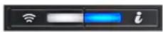
Figure 6. iDRAC Quick Sync 2 indicator
Table 3. iDRAC Quick Sync 2 indicators and descriptions
| iDRAC Quick Sync 2 indicator code | Condition Corrective action | |
| Off (default state) Indicates that the iDRAC Quick Sync 2 feature is turned off. Press the iDRAC Quick Sync 2 button to turn on the iDRAC Quick Sync 2 feature. | If the LED fails to turn on, reseat the cable and check.If the problem persists, see the Getting help section. | |
| Solid white Indicates that iDRAC Quick Sync 2 is ready to communicate. Press the iDRAC Quick Sync 2 button to turn off. | If the LED fails to turn off, restart the system. If the problem persists, see the Getting help section. | |
| Blinks white rapidly Indicates data transfer activity. | If the indicator continues to blink indefinitely, see the Getting help section. | |
| Blinks white slowly Indicates that firmware update is in progress. | If the indicator continues to blink indefinitely, see the Getting help section. | |
| Blinks white five times rapidly and then turns off | Indicates that the iDRAC Quick Sync 2 feature is disabled. | Check if iDRAC Quick Sync 2 feature is configured to be disabled by iDRAC. If the problem persists, see the Getting help section. For more information, see www.dell.com/idracmanuals www.dell.com/operatingsystemmanuals. |
| Solid amber Indicates that the system is in fail-safe mode. | Restart the system. If the problem persists, see the Getting help section. | |
| Blinking amber Indicates that the iDRAC Quick Sync 2 hardware is not responding properly. | Restart the system. If the problem persists, see the Getting help section. | |
System health and system ID indicator codes
The system health and system ID indicator is located on the front panel of your system.
Figure 7. System health and system ID indicators
Table 4. System health and system ID indicator codes
System health and system ID indicator code Condition
| Solid blue Indicates that the system is turned on, system is healthy, and system ID mode is not active. Press the system health and system ID button to switch to system ID mode. |
| Blinking blue Indicates that the system ID mode is active. Press the system health and system ID button to switch to system health mode. |
| Solid amber Indicates that the system is in fail-safe mode. If the problem persists, see the Getting help section. |
| Blinking amber Indicates that the system is experiencing a fault. Check the System Event Log for specific error messages. For information about the event and error messages generated by the system firmware and agents that monitor system components, see the Error Code Lookup page at qrl.dell.com. |
Drive indicator codes
Each drive carrier has an activity LED indicator and a status LED indicator. The indicators provide information about the current status of the drive. The activity LED indicator indicates whether the drive is currently in use or not. The status LED indicator indicates the power condition of the drive.

text_image
1 2 3Figure 8. Drive indicators
- Drive activity LED indicator
- Drive status LED indicator
- Drive capacity label
NOTE: If the drive is in the Advanced Host Controller Interface (AHCI) mode, the status LED indicator does not turn on.
Table 5. Drive indicator codes
Drive status indicator code Condition
Flashes green twice per second Identifying drive or preparing for removal.
Off Drive ready for removal.

NOTE: The drive status indicator remains off until all drives are initialized after the system is turned on. Drives are not ready for removal during this time.
Flashes green, amber, and then turns off Predicted drive failure.
Flashes amber four times per second Drive failed.
Flashes green slowly Drive rebuilding.
Solid green Drive online.
Flashes green for three seconds, amber for three seconds, and Rebuild stopped. then turns off after six seconds
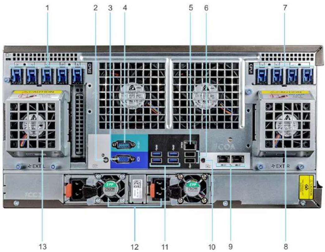
Back view of the system
The back view displays the features available on the back of the system.

text_image
7 6 5 4 3 2 1 8 9 10 11 EPP 1100W EPP 1100WFigure 9. Back view of the tower configuration
- PCIe expansion card slots 2. System ID button/indicator
- VGA port 4. Serial port
- iDRAC9 dedicated network port 6. USB 2.0 port (2)
- PCIe expansion card slots 8. NIC port (2)
- System Identification connector 10. USB 3.0 port (4)
- Power supply unit (2)
text_image
1 2 3 4 5 6 7 CCPU2 COCA EXT L COCA EXT R EPP 750W EPP 750W 13 12 11 10 9 8Figure 10. Back view of the rack configuration
- PCIe expansion card slots 2. System ID button/indicator
- VGA port 4. Serial port
- iDRAC9 dedicated network port 6. USB 2.0 port (2)
- PCIe expansion card slots 8. Right external fan (available only with GPGPU configuration)
- NIC port (2) 10. System Identification connector
- USB 3.0 port (4) 12. Power supply unit (2)
- Left external fan (available only with GPGPU configuration)
NIC indicator codes
Each NIC on the back of the system has indicators that provide information about the activity and link status. The activity LED indicator indicates if data is flowing through the NIC, and the link LED indicator indicates the speed of the connected network.

text_image
1 2Figure 11. NIC indicator codes
- link LED indicator
- activity LED indicator
Table 6. NIC indicator codes
Status Condition
Link and activity indicators are off The NIC is not connected to the network.
Status Condition
| Link indicator is green and activity indicator is blinking green | The NIC is connected to a valid network at its maximum port speed and data is being sent or received. |
| Link indicator is amber and activity indicator is blinking green | The NIC is connected to a valid network at less than its maximum port speed and data is being sent or received. |
| Link indicator is green and activity indicator is off | The NIC is connected to a valid network at its maximum port speed and data is not being sent or received. |
| Link indicator is amber and activity indicator is off | The NIC is connected to a valid network at less than its maximum port speed and data is not being sent or received. |
Link indicator is blinking green and activity is off NIC identify is enabled through the NIC configuration utility.
NOTE: The LOM (Broadcom 57416) is compatible with 10GBASE-T IEEE 802.3an and 1000 BASE-T IEEE 802.3ab.
Power supply unit indicator codes
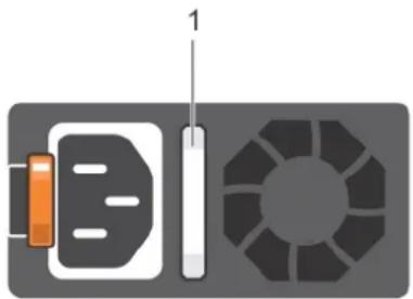
AC power supply units (PSUs) have an illuminated translucent handle that serves as an indicator.
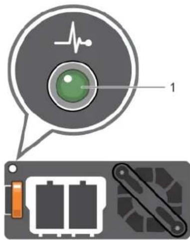
The DC PSUs have an LED that serves as an indicator.
The indicator shows whether power is present or if a power fault has occurred.
natural_image
Diagram of a battery, resistor, and circular device with numbered label (no text or symbols on components)Figure 12. AC PSU status indicator
- AC PSU status indicator/handle
Table 7. AC PSU status indicator codes
Power indicator codes Condition
Green A valid power source is connected to the PSU and the PSU is operational.
Blinking amber Indicates a problem with the PSU.
Not illuminated Power is not connected to the PSU.
Blinking green When the firmware of the PSU is being updated, the PSU handle blinks green.
CAUTION: Do not disconnect the power cord or unplug the PSU when updating firmware. If firmware update is interrupted, the PSUs do not function.
Blinking green and turns off
When hot-plugging a PSU, the PSU handle blinks green five times at a rate of 4 Hz and turns off. This indicates a PSU mismatch with respect to efficiency, feature set, health status, or supported voltage.
CAUTION: If two PSUs are installed, both the PSUs must have the same type of label; for example, Extended Power Performance (EPP) label. Mixing PSUs from previous generations of PowerEdge servers is not supported, even if the PSUs have the same power rating. This results in a PSU mismatch condition or failure to turn the system on.
CAUTION: When correcting a PSU mismatch, replace only the PSU with the blinking indicator. Swapping the PSU to make a matched pair can result in an error condition and unexpected system shutdown. To change from a high output configuration to a low output configuration or vice versa, you must turn off the system.
CAUTION: AC PSUs support both 240 V and 120 V input voltages with the exception of Titanium PSUs, which support only 240 V. When two identical PSUs receive different input voltages, they can output different wattages, and trigger a mismatch.
CAUTION: If two PSUs are used, they must be of the same type and have the same maximum output power.
CAUTION: Combining AC and DC PSUs is not supported and triggers a mismatch.
text_image
Diagram showing a device with an ECG inside a circular component and its internal components, including battery modules and a switch.Figure 13. DC PSU status indicator
- DC PSU status indicator
Table 8. DC PSU status indicator codes
Power indicator codes Condition
Green A valid power source is connected to the PSU and the PSU is operational.
Blinking amber Indicates a problem with the PSU.
Not illuminated Power is not connected to the PSU.
Blinking green When hot-plugging a PSU, the PSU indicator blinks green. This indicates that there is a PSU mismatch with respect to efficiency, feature set, health status, or supported voltage.
CAUTION: If two PSUs are installed, both the PSUs must have the same type of label; for example, Extended Power Performance (EPP) label. Mixing PSUs from previous generations of PowerEdge servers is not supported, even if the PSUs have the same power rating. This results in a PSU mismatch condition or failure to turn the system on.
CAUTION: When correcting a PSU mismatch, replace only the PSU with the blinking indicator. Swapping the PSU to make a matched pair can result in an error condition and unexpected system shutdown. To change from a High Output configuration to a Low Output configuration or vice versa, you must turn off the system.
CAUTION: If two PSUs are used, they must be of the same type and have the same maximum output power.
CAUTION: Combining AC and DC PSUs is not supported and triggers a mismatch.
Locating the Service Tag of your system
You can identify your system using the unique Express Service Code and Service Tag. Pull out the information tag in front of the system to view the Express Service Code and Service Tag. Alternatively, the information may be on a sticker on the chassis of the system. The
mini Enterprise Service Tag (EST) is found on the back of the system. This information is used by Dell to route support calls to the appropriate personnel.

text_image
2W17QM1 6290523001 5
text_image
2 3 4 Provider and Manage ODM Pass OpenManage Module (ODM App) 1. Downloaded ODM from https:// Google Tools and Teams 2. Add ODM, save the ODM to add ODM to automatically enter right ODM ENTERPRISE ADC ODM DEFAULT POST-HSD 00-08-08-08-08 A12-456798C 00-08-08-08-08Figure 14. Locating Service Tag of your system
- information tag (top view) 2. information tag (back view)
- OpenManage Mobile (OMM) label 4. iDRAC MAC address and iDRAC secure password label
- Service Tag
System information label
PowerEdge T640 – system information label
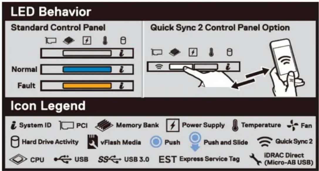
text_image
LED Behavior Standard Control Panel Normal Fault Quick Sync 2 Control Panel Option Icon Legend System ID PCI Memory Bank Power Supply Temperature Fan Hard Drive Activity vFlash Media Push Push and Slide Quick Sync 2 CPU USB SS USB 3.0 EST Express Service Tag iDRAC Direct (Micro-AB USB)Figure 15. LED behavior
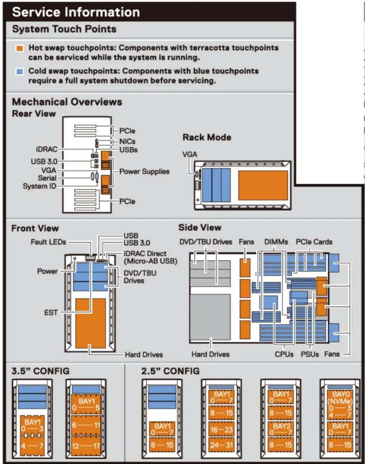
text_image
Service Information System Touch Points Hot swap touchpoints: Components with terracotta touchpoints can be serviced while the system is running. Cold swap touchpoints: Components with blue touchpoints require a full system shutdown before servicing. Mechanical Overviews Rear View PCIe NICs USBs iDRAC USB 3.0 VGA Serial System ID Power Supplies PCIe Rack Mode VGA Front View Fault LEDs USB USB 3.0 iDRAC Direct (Micro-AB USB) Power DVD/TBU Drives EST Hard Drives Side View DVD/TBU Drives Fans DIMMs PCIe Cards Hard Drives CPUs PSUs Fans 3.5" CONFIG BAY1 0—5 6—11 12—17 2.5" CONFIG BAY1 0—7 8—15 16—23 24—31 BAY1 0—7 8—15 BAY0 (NVMe) 0—3 4—7 BAY1 0—7 8—15Figure 16. Configuration and layout
Service Information
Electrical Overview
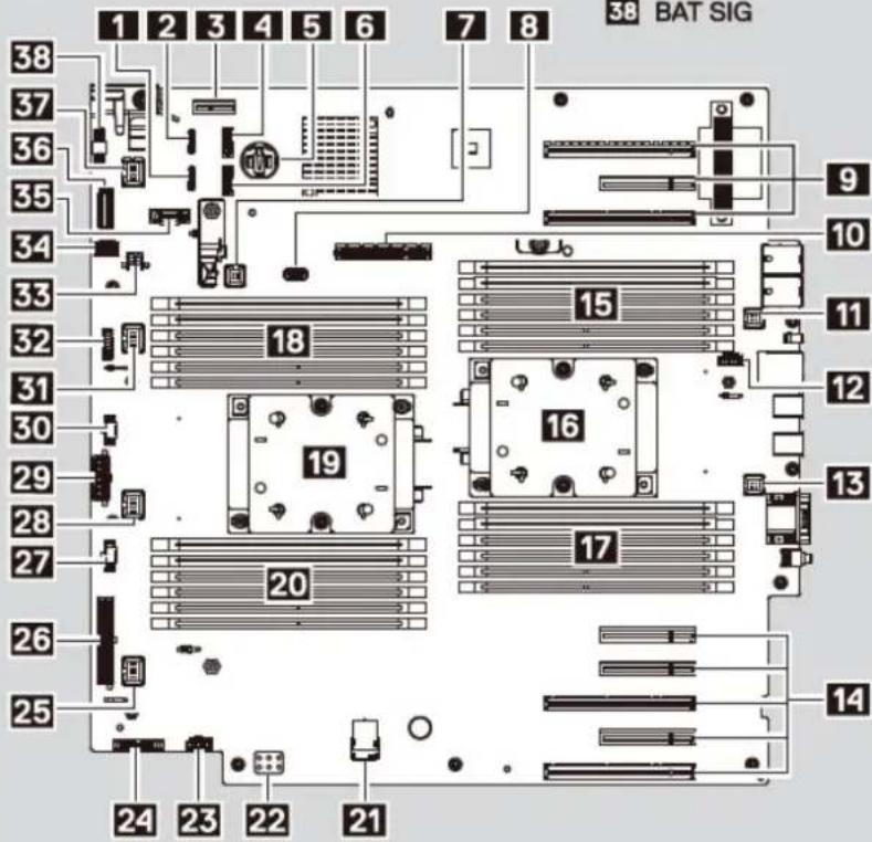
System Board Information
1 SATA B
13 Fan2
24 PIB Signals
2 SATA A
14 PCIe Card Slot (CPU2)
25 Fan6
3 IDSDM+vFlash
(CFO2)
26 PWR_CONN_1
4 CDROM
15 DIMMs For CPU2 Channels 0&1&2
27 BP_SIG2
5 Battery
16 CPU2
28 Fan5
6 TBU
17 DIMMs For CPU2
29 PWR_CONN_2
7 Intrusion
Channels 3&4&5
30 BP_SIG1
8 Internal USB
18 DIMMs For CPU1 Channels 3&4&5
31 Fan4
9 PCIe Card Slot (CPU1)
19 CPU1
32 BP_SIG0
10 PERC
20 DIMMs For CPU1 Channels 0&1&2
33 BAT PWR
11 Fan1
22 PWRD_EN&NVRAM_CLR
34 Front VGA
12 Fan Ext R
23 Fan Ext L
35 Front USB
36 Control Panel Signals
37 Fan3
38 BAT SIG
text_image
38 BAT SIG 1 2 3 4 5 6 7 8 38 37 36 35 34 33 32 31 30 29 28 27 26 25 18 15 16 17 20 24 23 22 21Jumper Settings
| Jumper | Setting | Description |
| NVRAM_CLR↓ | (default) | BIOS configuration settings retained at system boot. |
| BIOS configuration settings cleared at system boot. | ||
| (default) | BIOS password is enabled. | |
| ↑PWRD_EN | BIOS password is disabled.iDRAC local access is unlocked at next AC power cycle. |
Figure 17. Electrical overview

bar_stacked
| Configuration | Memory-Optimized | Mirroring | Memory Sparings | | ------------- | ---------------- | --------- | --------------- | | A6 | 1 | 0 | 0 | | A12 | 0 | 0 | 0 | | A5 | 0 | 0 | 0 | | A11 | 0 | 0 | 0 | | A4 | 0 | 0 | 0 | | A10 | 0 | 0 | 0 | | A7 | 1 | 0 | 0 | | A1 | 0 | 0 | 0 | | A8 | 0 | 0 | 0 | | A2 | 0 | 0 | 0 | | A9 | 0 | 0 | 0 | | A3 | 0 | 0 | 0 | | B3 | 1 | 0 | 0 | | B9 | 0 | 0 | 0 | | B2 | 0 | 0 | 0 | | B8 | 0 | 0 | 0 | | B1 | 0 | 0 | 0 | | B7 | 0 | 0 | 0 | | B10 | 1 | 0 | 0 | | B4 | 0 | 0 | 0 | | B11 | 0 | 0 | 0 | | B5 | 0 | 0 | 0 | | B12 | 0 | 0 | 0 | | B6 | 0 | 0 | 0 | | Memory Population Sequence: Memory-Optimized: Mirroring: Memory sparing details are documented in the Installation and Service Manual. | | | | | Memory Population Sequence: Memory-Optimized: Mirroring: Memory sparing details are documented in the Installation and Service Manual.Figure 18. Memory information

Figure 19. System tasks
Technical specifications
The technical and environmental specifications of your system are outlined in this section.
Topics:
- Chassis dimensions
- Chassis weight
- Processor specifications
• Supported operating systems
• Cooling fans - PSU specifications
• System battery specifications - Expansion bus specifications
• Memory specifications
• Storage controller specifications - Drive specifications
- Ports and connectors specifications
• Video specifications
• Environmental specifications
Chassis dimensions

text_image
TOP VIEW Xa Xb Za Zc Zb SIDE VIEW Bezel or Outer Most Feature Ya Yb Yc Tower Foot Optional CasterFigure 20. Dimensions of the Dell EMC PowerEdge T640 system
Table 9. The dimensions of the Dell EMC PowerEdge T640 system
| Xa Xb Ya Yb Yc Za (with | Bezel) | Zb Zc | |||||
| 304.5 mm(11.99 inches) | 217.9 mm (8.57 inches) | 434.5 mm(17.10 inches) | 443.5 mm(17.46 inches) | 471.5 mm(18.56 inches) | 15.9 mm (0.62 inches) | 659.9 mm(25.98 inches) | 692.8 mm(27.27 inches) |
Chassis weight
Table 10. Chassis weight
System Maximum weight (with all hard drives/SSDs)
| 32 x 2.5-inch 42.36 Kg (93.38 lb) |
| 18 x 3.5-inch 49.65 Kg (109.45 lb) |
Processor specifications
The Dell EMC PowerEdge T640 system supports up to two Intel Xeon Scalable processors, up to 28 cores per processor.
Supported operating systems
The PowerEdge T640 system supports the following operating systems:
- Canonical Ubuntu LTS
- Citrix XenServer
- Microsoft Windows Server with Hyper-V
• Red Hat Enterprise Linux
• SUSE Linux Enterprise Server - VMware ESXi
For more information on the specific versions and additions, see https://www.dell.com/support/home/Drivers/SupportedOS/poweredge-t640.
Cooling fans
Cooling fan specifications
The cooling fans are integrated into the system to dissipate the heat generated by the functioning of the system. These fans provide cooling for the processors, expansion cards, and memory modules.
Your system supports a total of eight fans, including six hot-swappable fans and two external fans. Two hot-swappable fans are mounted in rear side of the air shroud. The other four hot-swappable (middle) fans are mounted in the fan assembly that is located in the chassis between the hard drive bay and the processors. The two external fans are mounted on the outside of the chassis for GPU configurations. There are two additional fans integrated in the power supplies to cool the power supplies and provide additional cooling for the whole system.
The below listed configurations, features, and the PCIe expansion cards are supported only with the four hot-swappable (middle) fans installed:
- Fan redundancy
- Fresh air condition
• NVMe/PCIe SSD - 3.5 inch x 18 hard drives chassis
• Mellanox CX4 DP 100 Gb QSFP NIC (0272F)
• Mellanox CX4 DP 100 Gb NIC (068F2)
• Mellanox CX4 SP 100 Gb NIC (6W1HY)
• Mellanox DP 40 Gb QSFP NIC (C8Y42)
• Intel QP 10 Gb Base-T NIC (K5V44)
• Solarflare Sunspot DP 10Gb NIC (NPHCM)
• Solarflare Nova DP 10Gb NIC (WY7T5)
• Qlogic DP 10Gb V1 NIC (VCXN5)
Listed below are the restrictions for fan redundancy:
- GPGPU configurations are not supported at 35deg. C of ambient or above.
- Mellanox 100G NICs are not supported.
For information on the restriction for fresh air condition, see the Expanded operating temperature restrictions topic in the Technical Specification section.
Cooling fan matrix
| Chassis FAN1, FAN2 (Standard [STD]) | FAN3, FAN4, FAN5, FAN6 (Standard [STD]/High performance [HPR]) | FAN_EXT_R, FAN_EXT_L | Fan configuration |
3.5 inch x 8 Yes -- Base configuration
3.5 inch x 18 Yes Yes (STD) - Rich configuration
2.5 inch x 16 Yes -- Base configuration
2.5 inch x 32 Yes -- Base configuration
2.5 inch x 16 + NVMe Yes Yes (STD) - Rich configuration
Fan redundancy, FA and high cooling tier PCIe card Yes Yes (STD) - Rich configuration
GPGPU card Yes Yes (HPR) Yes GPU configuration
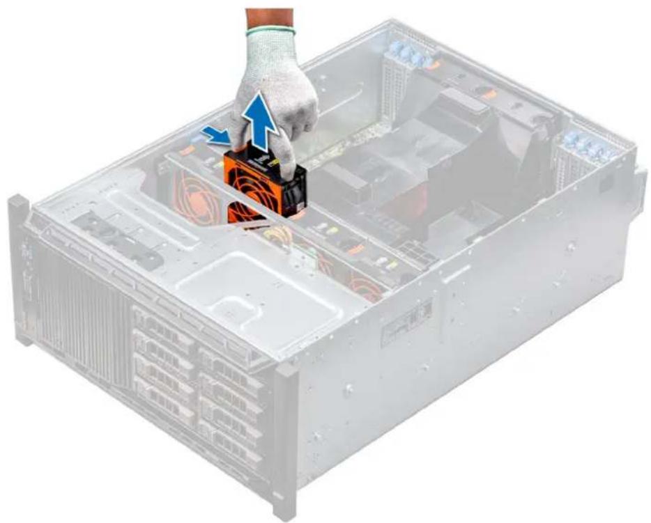
Removing a middle or rear cooling fan
The procedure for removing a standard and a high performance fans is identical.
Prerequisites

NOTE: Opening or removing the system cover when the system is on may expose you to a risk of electric shock. Exercise utmost care while removing or installing cooling fans.

CAUTION: The cooling fans are hot swappable. To maintain proper cooling while the system is on, replace only one fan at a time.
- Follow the safety guidelines listed in Safety instructions.
- Follow the procedure listed in Before working inside your system.
Steps
Press the release tab and lift the cooling fan out of the cooling fan assembly.
natural_image
Illustration of a server rack with an orange CPU socket and blue directional arrows indicating process (no text or symbols)Figure 21. Removing a middle cooling fan
Next steps
- Installing a middle or rear cooling fan.
Installing a middle or rear cooling fan
The procedure for installing a standard and a high performance fans is identical.
Prerequisites

NOTE: Opening or removing the system cover when the system is on may expose you to a risk of electric shock. Exercise utmost care while removing or installing cooling fans.

CAUTION: The cooling fans are hot swappable. To maintain proper cooling while the system is on, replace only one fan at a time.
- Follow the safety guidelines listed in Safety instructions.
- Follow the procedure listed in Before working inside your system.
Steps
Holding the release tab, align the connector at the base of the cooling fan with the connector on the system board.

natural_image
Hand installing a CD drive into a server rack (no text or symbols visible)Figure 22. Installing a middle cooling fan
Next steps
- Follow the procedure listed in After working inside your system.
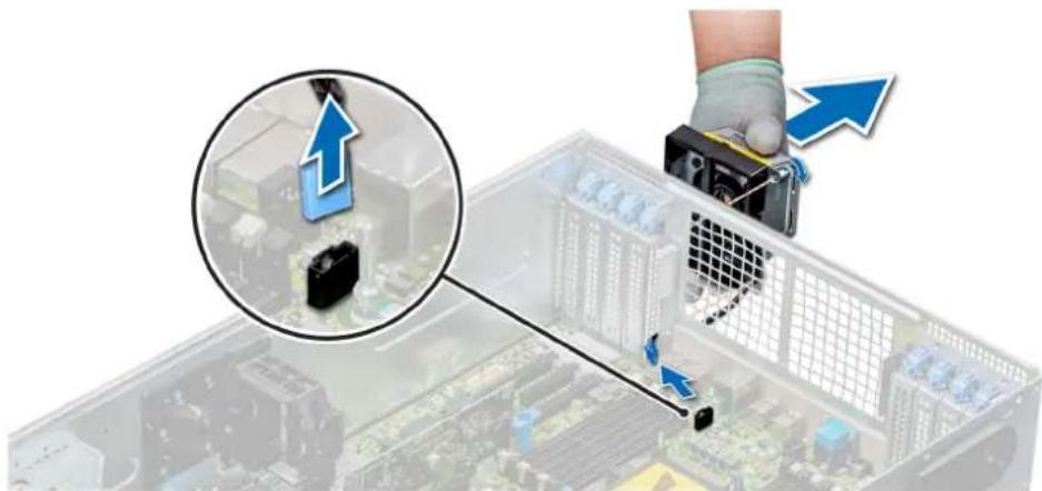
Removing the right external fan
Prerequisites
NOTE: Opening or removing the system cover when the system is on may expose you to a risk of electric shock. Exercise utmost care while removing or installing cooling fans.
NOTE: The procedure to remove the left external fan is similar to removing the right rear fan.
- Follow the safety guidelines listed in Safety instructions.
- Remove the GPU air shrouds.
- Remove the air shroud.
Steps
- Disconnect the fan cable from the system board.
- Using the Phillips #2 screwdriver, loosen the captive screws that secure the fan to the system.
- Lift the fan away, while guiding the fan cable through the cable vent.
natural_image
Illustration of a server rack with a hand holding a device, showing a close-up of the rack and a magnified inset of its cable (no text or symbols present)Figure 23. Removing the right external fan
Next steps
- Installing the right external fan.
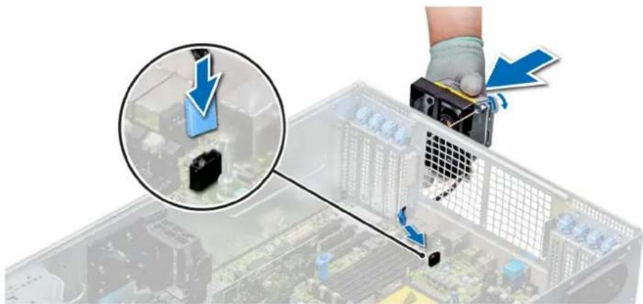
Installing the right external fan
Prerequisites
NOTE: The procedure to install the left external fan is similar to installing the right rear fan.
Follow the safety guidelines listed in Safety instructions.
Steps
- Guiding the fan cable through the cable vent, install the external fan over the PCIe slots.
- Using the Phillips #2 screwdriver, secure the fan in place.
- Connect the fan cable to the connected on the system board.
natural_image
Close-up of a hand using a tool to adjust or install electronic components on a computer motherboard (no visible text or symbols)Figure 24. Install the right external fan
Next steps
- Install the air shroud.
- Install the GPU air shrouds.
- Follow the procedure listed in After working inside your system.
PSU specifications
The Dell EMC PowerEdge T640 system supports up to two AC or DC redundant power supply units (PSUs).
Table 12. PSU specifications
| PSU Class Heat dissipation | (maximum) | Frequency Voltage Current | |||
| 495 W AC Platinum 1908 BTU/hr 50/60 Hz 100–240 V AC, autoranging 6.5 A–3 A | |||||
| 750 W AC Platinum 2891 BTU/hr 50/60 Hz 100–240 V AC, autoranging 10 A–5 A | |||||
| 750 W AC Titanium 2843 BTU/hr 50/60 Hz 200–240 V AC, autoranging 5 A | |||||
| 750 W Mixed Mode HVDC (for China only) | Platinum 2891 BTU/hr 50/60 Hz 100-200 V AC, autoranging 10 A–5 A | ||||
| Platinum 2891 BTU/hr NA 240 V DC, autoranging 4.5 A | |||||
| 750 W Mixed Mode | Platinum 2891 BTU/hr 50/60 Hz 100-200 V AC, autoranging 10 A–5 A | ||||
| Platinum(For China only) | 2891 BTU/hr NA 240 V DC, autoranging 5 A | ||||
| 1100 W AC | Platinum 4100 BTU/hr 50/60 Hz 100–240 V AC, autoranging 12 A–6.5 A | ||||
| 1100 W DC | Gold | 4416 BTU/hr | - | (-48 V to -60 V) DC, autoranging | 32 A |
| 1600 W AC | Platinum | 6000 BTU/hr | 50/60 Hz | 100–240 V AC, autoranging | 10 A |
| 2000 W Mix Mode | Platinum | 7500 BTU/hr | 50/60 Hz | 100–200 V AC, autoranging | 11.5 A |
| 2000 W Mix Mode | Platinum | 7500 BTU/hr | 50/60 Hz | 240 V AC, autoranging | 11.8 A |
| 2400 W AC | Platinum | 9000 BTU/hr | 50/60 Hz | 100–240 V AC, autoranging | 16 A |
NOTE: Heat dissipation is calculated using the PSU wattage rating.
NOTE: This system is also designed to connect to the IT power systems with a phase-to-phase voltage not exceeding 240 V.
NOTE: If a system with 2400 W AC PSU operates at low line 100–120 V AC, then the power rating per PSU is derated to 1400 W.
NOTE: If a system with 2000 W AC PSU operates at low line 100–120 V AC, then the power rating per PSU is derated to 1000 W.
NOTE: If a system with 1600 W AC PSU operates at low line 100–120 V AC, then the power rating per PSU is derated to 800 W.
NOTE: If a system with 1100 W AC PSU operates at low line 100–120 V AC, then the power rating per PSU is derated to 1050 W.
System battery specifications
The Dell EMC PowerEdge T640 system supports CR 2032 3.0-V lithium coin cell system battery.
Expansion bus specifications
The Dell EMC PowerEdge T640 system supports PCI express (PCIe) generation 3 and 2 expansion cards. The following table describes the supported expansion cards:
Table 13. Supported PCI express generation 3 expansion cards
| PCIe Slot Processor Connection | Height Length Link Width Slot Width |
| 0 (Internal PERC/HBA Slot) | Processor 1 Full Height Half Length x8 x8 |
| 1 (Gen3) Processor 1 Full Height Full Length x16 x16 | |
| 2 (Gen3) Processor 1 Full Height Full Length x4 x8 | |
| 3 (Gen3) Processor 1 Full Height Full Length x16 x16 | |
| 4 (Gen3) Processor 2 Full Height Half Length x8 x8 | |
| 5 (Gen3) Processor 2 Full Height Full Length x4 x8 | |
| 6 (Gen3) Processor 2 Full Height Full Length x16 x16 | |
| 7 (Gen3) Processor 2 Full Height Full Length x8 x8 | |
| 8 (Gen3) Processor 2 Full Height Full Length x16 x16 | |
NOTE: To use PCIe slots 4, 5, 6, 7, and 8 both the processors must be installed.
NOTE: The expansion card slots are not hot-swappable.
Memory specifications
Table 14. Memory specifications
| DIMM type | DIMM rank | DIMM capacity | Single processor Dual processors | |||
| Minimum RAM Maximum RAM | Minimum RAM | Maximum RAM | ||||
| RDIMM | Single rank | 8 GB | 8 GB | 96 GB | 16 GB | 192 GB |
| Single rank | 16 GB 16 GB | 192 GB 32 GB 384 GB | ||||
| LRDIMM | Dual rank | 32 GB / 64 GB | 32 GB | 384 GB | 64 GB | 768 GB |
| Quad rank | 64 GB | 64 GB | 768 GB | 128 GB | 1536 GB | |
| Octal rank | 128 GB | 128 GB | 1536 GB | 256 GB | 3072 GB | |
| NVDIMM-N | Single rank | 16 GB | Not supported with single processor | Not supported with single processor | RDIMM: 192 GBNVDIMM-N: 16 GB | RDIMM: 384 GBNVDIMM-N: 192 GB |
NOTE: 8 GB RDIMMs and NVDIMM-N must not be mixed.
NOTE: A minimum of two processors are required for any configuration that supports NVDIMM-N DIMMs.
Storage controller specifications
The Dell EMC PowerEdge T640 system supports:
• Internal controllers: PERC H730P, H740P, HBA330, H330, Software RAID (SWRAID) S140
External PERC (RAID): H840
• External HBAs (non-RAID): 12 Gbps SAS HBA
• Boot Optimized Storage Subsystem: HWRAID 2 x M.2 SSDs 120GB or 240GB
Drive specifications
Hard drives
The Dell EMC PowerEdge T640 system supports:
Backplane configuration options:
- 8 x 3.5-inch SAS, SATA, Near-Line SAS, SSD
- 16 x 2.5-inch SAS, SATA, Near-Line SAS, SSD, NVMe drives
- 18 x 3.5-inch SAS, SATA, Near-Line SAS, SSD
- 32 x 2.5-inch SAS, SATA, Near-Line SAS, SSD
- SW RAID on 3.5-inch SAS, SATA, Near-Line SAS, SSD
- 8 x NVMe drive
Internal hard drive bay and hot-plug backplane:
- Up to 8 x 3.5-inch SAS, SATA, Near-Line SAS, SSD drives
- Up to 16 x 2.5-inch SAS, SATA, Near-Line SAS, SSD, NVMe drives with optional flex bay
- Up to 18 x 3.5-inch SAS, SATA, Near-Line SAS, SSD drives without optional flex bay
- Up to 32 x 2.5-inch SAS, SATA, Near-Line SAS, SSD drives with optional flex bay
Optical drive
The Dell EMC PowerEdge T640 system supports one optional slim SATA DVD-ROM drive or DVD +/-RW drive.
Ports and connectors specifications
USB ports
The Dell EMC PowerEdge T640 system supports the following USBs.
Table 15. USB specifications
System Front panel Back panel Internal
| PowerEdge T640 | One USB 2.0 compliant port and one USB 3.0 compliant portOne iDRAC USB MGMT port (USB 2.0) | Six USB portsFour USB 3.0 compliant portsTwo USB 2.0 compliant ports | One USB 3.0 compliant port |
NIC ports
The Dell EMC PowerEdge T640 system supports two onboard Network Interface Controller (NIC) ports on the back panel, which is available in the following NIC configurations:
- Two 10 Gbps
NOTE: The LOM (Broadcom 57416) is compatible with 10GBASE-T IEEE 802.3an and 1000 BASE-T IEEE 802.3ab.
VGA ports
The Video Graphic Array (VGA) port enables you to connect the system to a VGA display. The Dell EMC PowerEdge T640 system supports two 15-pin VGA ports on the front and back panels.
NOTE: The front VGA port is available only with the rack configuration.
Serial connector
The Dell EMC PowerEdge T640 system supports one serial connector on the back panel, which is a 9-pin connector, Data Terminal Equipment (DTE), 16550-compliant.
Internal Dual SD Module with vFlash card
The Dell EMC PowerEdge T640 system supports Internal Dual SD module (IDSDM) and vFlash card. In 14th generation of PowerEdge servers, IDSDM and vFlash card are combined into a single card module, and are available in anyone of these configurations:
• vFlash
- vFlash and IDSDM
The IDSDM/vFlash module sits in the back of the system, in a Dell-proprietary slot. The IDSDM/vFlash module supports three micro SD cards (two cards for IDSDM and one card for vFlash). The micro SD cards capacity for IDSDM are 16/32/64 GB while for vFlash the microSD card capacity is 16 GB.
NOTE: The write-protect switch is on the IDSDM or vFlash module.
NOTE: The IDSDM supports only Micro SD cards.
Video specifications
The Dell EMC PowerEdge T640 system supports integrated Matrox G200eW3 graphics controller with 16 MB of video frame buffer.
Table 16. Supported video resolution options
Resolution Refresh rate (Hz) Color depth (bits)
| 1024 × 768 60 8, 16, 32 |
| 1280 × 800 60 8, 16, 32 |
| 1280 × 1024 60 8, 16, 32 |
| 1360 × 768 60 8, 16, 32 |
| 1440 × 900 60 8, 16, 32 |
| 1600 × 900 60 8, 16, 32 |
| 1600 × 1200 60 8, 16, 32 |
| 1680 × 1050 60 8, 16, 32 |
| 1920 × 1080 60 8, 16, 32 |
| 1920 × 1200 60 8, 16, 32 |
NOTE: 1920 x 1080 and 1920 x 1200 resolutions are only supported in reduced blanking mode.
Environmental specifications
NOTE: For additional information about environmental certifications, please refer to the Product Environmental Datasheet located with the Manuals & Documents on www.dell.com/poweredgemanuals
Table 17. Temperature specifications
Temperature Specifications
| Storage - 40^ C to 65^ C( -40^ Fto149^ F) |
| Continuous operation (for altitude less than 950 m or 3117 10^ C to 35^ C( 50^ Fto95^ F) with no direct sunlight on the equipment. ft) |
| Fresh air For information about fresh air, see Expanded Operating Temperature section. |
Temperature Specifications
Maximum temperature gradient (operating and storage) 20^ / h (68^ / h)
Table 18. Relative humidity specifications
Relative humidity Specifications
| Storage 5% to 95% RH with 33°C (91°F) maximum dew point. Atmosphere must be non-condensing at all times. |
Operating 10% to 80% relative humidity with 29^ C ( 84.2^ F) maximum dew point.
Table 19. Maximum vibration specifications
Maximum vibration Specifications
| Operating 0.26 G | rms at 5 Hz to 350 Hz (all operation orientations). |
| Storage 1.88 G | rms at 10 Hz to 500 Hz for 15 min (all six sides tested). |
Table 20. Maximum shock specifications
Maximum vibration Specifications
| Operating Six consecutively executed shock pulses in the positive and negative x, y, and z axes |
| Storage Six consecutively executed shock pulses in the positive and negative x, y, and z axes (one pulse on each side of the system) of 71 G for up to 2 ms. |
Table 21. Maximum altitude specifications
Maximum altitude Specifications
| Operating | 30482000 m (10,0006560 ft) |
| Storage 12,000 m (39,370 ft) |
Table 22. Operating temperature de-rating specifications
Operating temperature de-rating Specifications
| Up to 35°C (95°F) Maximum temperature is reduced by 1°C/300 m (1°F/547 ft) above 950 m(3,117 ft). |
| 35°C to 40°C (95°F to 104°F) Maximum temperature is reduced by 1°C/175 m (1°F/319 ft) above 950 m(3,117 ft). |
| 40°C to 45°C (104°F to 113°F) Maximum temperature is reduced by 1°C/125 m (1°F/228 ft) above 950 m(3,117 ft). |
Standard operating temperature
Table 23. Standard operating temperature specifications
Standard operating temperature Specifications
| Continuous operation (for altitude less than 950 m or 3117 ft) | 10°C to 35°C (50°F to 95°F) with no direct sunlight on the equipment. |
Expanded operating temperature
Table 24. Expanded operating temperature specifications
Expanded operating temperature Specifications
Continuous operation 5°C to 40°C at 5% to 85% RH with 29°C dew point.
NOTE: Outside the standard operating temperature (10°C to 35°C), the system can operate continuously in temperatures as low as 5°C and as high as 40°C.
For temperatures between 35^ C and 40^ C, de-rate maximum allowable temperature by 1^ C per 175 m above 950 m ( 1^ F per 319 ft).
≤ 1% of annual operating hours -5^ to 45^ at 5% to 90% RH with 29^ dew point.
NOTE: Outside the standard operating temperature (10°C to 35°C), the system can operate down to -5°C or up to 45°C for a maximum of 1% of its annual operating hours.
For temperatures between 40^ C and 45^ C, de-rate maximum allowable temperature by 1^ C per 125 m above 950 m ( 1^ F per 228 ft).
NOTE: When operating in the expanded temperature range, system performance may be impacted.
NOTE: When operating in the expanded temperature range, ambient temperature warnings maybe reported in the System Event Log.
Expanded operating temperature restrictions and Fresh Air restrictions
- Six hot swappable fans (standard fans) are required.
- Two PSUs in redundancy mode are required, but PSU failure is not supported.
- 3.5-inch x 18 hard drives is not supported.
- NVMe or PCIe SSD is not supported.
- GPGPU is not supported.
- Processor > 165 W is not supported.
- Internal TBU (tape backup drive) is not supported.
• Non-Dell qualified peripheral cards are not supported. - Peripheral cards consuming greater than 25 W are not supported.
- 128 GB LRDIMM is supported.
- NVDIMM is not supported.
- Mellanox 100 GB, Mellanox Navi DP/SP, Intel FortPond Solarflare Nova, Solarflare Sunspot are not supported.
Particulate and gaseous contamination specifications
The following table defines the limitations that help avoid any equipment damage or failure from particulate and gaseous contamination. If the levels of particulate or gaseous pollution exceed the specified limitations and result in equipment damage or failure, you may need to rectify the environmental conditions. Remediation of environmental conditions is the responsibility of the customer.
Table 25. Particulate contamination specifications
Particulate contamination Specifications
| Air filtration Data center air filtration as defined by ISO Class 8 per ISO 14644-1 with a 95% upper confidence limit. | |
| NOTE: The ISO Class 8 condition applies to data center environments only. This air filtration requirement does not apply to IT equipment designed to be used outside a data center, in environments such as an office or factory floor. | |
| NOTE: Air entering the data center must have MERV11 or MERV13 filtration. | |
| Conductive dust Air must be free of conductive dust, zinc whiskers, or other conductive particles. | |
Particulate contamination Specifications
| NOTE: This condition applies to data center and non-data center environments. | |
| Corrosive dust | • Air must be free of corrosive dust.• Residual dust present in the air must have a deliquescent point less than 60% relative humidity. |
| NOTE: This condition applies to data center and non-data center environments. |
Table 26. Gaseous contamination specifications
Gaseous contamination Specifications
| Copper coupon corrosion rate <300 Å/month per Class G1 as defined by ANSI/ISA71.04-2013. |
| Silver coupon corrosion rate <200 Å/month as defined by ANSI/ISA71.04-2013. |
NOTE: Maximum corrosive contaminant levels measured at ≤50% relative humidity.
Initial system setup and configuration
Setting up your system
Perform the following steps to set up your system:
Steps
- Unpack the system.
- Install the system into the rack. For more information about installing the system into the rack, see the Rail Installation Guide at www.dell.com/poweredgemanuals.
- Connect the peripherals to the system.
- Connect the system to its electrical outlet.
- Power on the system by pressing the power button or by using iDRAC.
- Power on the attached peripherals.
For more information about setting up your system, see the Getting Started Guide that shipped with your system.
iDRAC configuration
The Integrated Dell Remote Access Controller (iDRAC) is designed to make system administrators more productive and improve the overall availability of Dell systems. iDRAC alerts administrators about system issues and enables them to perform remote system management. This reduces the need for physical access to the system.
Options to set up iDRAC IP address
To enable communication between your system and iDRAC, you must first configure the network settings based on your network infrastructure.
NOTE: For static IP configuration, you must request for it at the time of purchase.
This option is set to DHCP by Default. You can set up the IP address by using one of the following interfaces:
| Interfaces | Document/Section |
| iDRAC Settings utility | Dell Integrated Dell Remote Access Controller User's Guide at www.dell.com/poweredgemanuals |
| Dell Deployment Toolkit | Dell Deployment Toolkit User's Guide at www.dell.com/openmanagemanuals > OpenManage Deployment Toolkit |
| Dell Lifecycle Controller | Dell Lifecycle Controller User's Guide at www.dell.com/poweredgemanuals |
| iDRAC Direct and Quick Sync 2 (optional) | See Dell Integrated Dell Remote Access Controller User's Guide at www.dell.com/poweredgemanuals |
NOTE: To access iDRAC, ensure that you connect the ethernet cable to the iDRAC9 dedicated network port. You can also access iDRAC through the shared LOM mode, if you have opted for a system that has the shared LOM mode enabled.
Log in to iDRAC
You can log in to iDRAC as:
- iDRAC user
- Microsoft Active Directory user
• Lightweight Directory Access Protocol (LDAP) user
If you have opted for secure default access to iDRAC, you must use the iDRAC secure default password available on the system Information tag. If you have not opted for secure default access to iDRAC, then use the default user name and password -root and calvin. You can also log in by using your Single Sign-On or Smart Card.
NOTE: You must have the iDRAC credentials to log in to iDRAC.
NOTE: Ensure that you change the default username and password after setting up the iDRAC IP address.
For more information about logging in to the iDRAC and iDRAC licenses, see the latest Integrated Dell Remote Access Controller User's Guide at www.dell.com/poweredgemanuals.
You can also access iDRAC by using RACADM. For more information, see the RACADM Command Line Interface Reference Guide at www.dell.com/poweredgemanuals.
Options to install the operating system
If the system is shipped without an operating system, install a supported operating system by using one of the following resources:
Table 27. Resources to install the operating system
| Resources Location | |
| iDRAC www.dell.com/idracmanuals | |
| Lifecycle Controller www.dell.com/idracmanuals > Lifecycle Controller | |
| OpenManage Deployment Toolkit www.dell.com/openmanagemanuals > OpenManage Deployment Toolkit | |
| Dell certified VMware ESXi www.dell.com/virtualizationsolutions | |
| Installation and How-to videos for supported operating systems on PowerEdge systems | Supported Operating Systems for Dell EMC PowerEdge systems |
Methods to download firmware and drivers
You can download the firmware and drivers by using any of the following methods:
Table 28. Firmware and drivers
| Methods Location | |
| From the Dell EMC support site www.dell.com/support/home | |
| Using Dell Remote Access Controller Lifecycle Controller (iDRAC with LC) | www.dell.com/idracmanuals |
| Using Dell Repository Manager (DRM) www.dell.com/openmanagemanuals > Repository Manager | |
| Using Dell OpenManage Essentials www.dell.com/openmanagemanuals > OpenManage Essentials | |
| Using Dell OpenManage Enterprise www.dell.com/openmanagemanuals > OpenManage Enterprise | |
| Using Dell Server Update Utility (SUU) | www.dell.com/openmanagemanuals > Server Update Utility |
| Using Dell OpenManage Deployment Toolkit (DTK) | www.dell.com/openmanagemanuals > OpenManage Deployment Toolkit |
| Using iDRAC virtual media www.dell.com/idracmanuals | |
Downloading drivers and firmware
Dell EMC recommends that you download and install the latest BIOS, drivers, and systems management firmware on your system.
Prerequisites
Ensure that you clear the web browser cache before downloading the drivers and firmware.
Steps
-
Go to www.dell.com/support/home.
-
In the Drivers & Downloads section, type the Service Tag of your system in the Enter a Service Tag or product ID box, and then click Submit.

NOTE: If you do not have the Service Tag, select Detect Product to allow the system to automatically detect the Service Tag, or click View products, and navigate to your product.
- Click Drivers & Downloads.
The drivers that are applicable to your system are displayed.
- Download the drivers to a USB drive, CD, or DVD.
Pre-operating system management applications
You can manage basic settings and features of a system without booting to the operating system by using the system firmware.
Topics:
- Options to manage the pre-operating system applications
- System Setup
- Dell Lifecycle Controller
- Boot Manager
- PXE boot
Options to manage the pre-operating system applications
Your system has the following options to manage the pre-operating system applications:
- System Setup
- Dell Lifecycle Controller
- Boot Manager
- Preboot Execution Environment (PXE)
System Setup
By using the System Setup screen, you can configure the BIOS settings, iDRAC settings, and device settings of your system.

NOTE: Help text for the selected field is displayed in the graphical browser by default. To view the help text in the text browser, press F1.
You can access system setup by one of the following:
- Standard graphical browser—The browser is enabled by default.
- Text browser—The browser is enabled by using Console Redirection.
Viewing System Setup
To view the System Setup screen, perform the following steps:
Steps
- Power on, or restart your system.
- Press F2 immediately after you see the following message:
F2 = System Setup

NOTE: If your operating system begins to load before you press F2, wait for the system to finish booting, and then restart your system and try again.
System Setup details
The System Setup Main Menu screen details are explained as follows:
Option Description
System BIOS Enables you to configure BIOS settings.
iDRAC Settings Enables you to configure the iDRAC settings.
The iDRAC settings utility is an interface to set up and configure the iDRAC parameters by using UEFI (Unified Extensible Firmware Interface). You can enable or disable various iDRAC parameters by using the iDRAC settings utility. For more information about this utility, see Integrated Dell Remote Access Controller User's Guide at www.dell.com/poweredgemanuals.
Device Settings Enables you to configure device settings.
System BIOS
You can use the System BIOS screen to edit specific functions such as boot order, system password, and setup password, set the SATA and PCIe NVMe RAID mode, and enable or disable USB ports.
Viewing System BIOS
To view the System BIOS screen, perform the following steps:
Steps
- Power on, or restart your system.
- Press F2 immediately after you see the following message:
F2 = System Setup

NOTE: If the operating system begins to load before you press F2, wait for the system to finish booting, and then restart the system and try again.
- On the System Setup Main Menu screen, click System BIOS.
System BIOS Settings details
About this task
The System BIOS Settings screen details are explained as follows:
Option
Description
System
Provides information about the system such as the system model name, BIOS version, and Service Tag.
Information
Memory Settings Provides information and options related to the installed memory.
Processor
Provides information and options related to the processor such as speed and cache size.
Settings
SATA Settings Provides options to enable or disable the integrated SATA controller and ports.
NVMe Settings
Provides options to change the NVMe settings. If the system contains the NVMe drives that you want to configure in a RAID array, you must set both this field and the Embedded SATA field on the SATA Settings menu to RAID mode. You might also need to change the Boot Mode setting to UEFI. Otherwise, you should set this field to Non-RAID mode.
Boot Settings
Provides options to specify the Boot mode (BIOS or UEFI). Enables you to modify UEFI and BIOS boot settings.
Network Settings Provides options to manage the UEFI network settings and boot protocols.
Legacy network settings are managed from the Device Settings menu.
Integrated Devices
Provides options to manage integrated device controllers and ports, specifies related features and options.
Serial
Provides options to manage the serial ports, their related features and options.
Communication
Option Description
| System Profile Settings | Provides options to change the processor power management settings, and memory frequency. |
| System Security | Provides options to configure the system security settings, such as system password, setup password, Trusted Platform Module (TPM) security, and UEFI secure boot. It also manages the power button on the system. |
| Redundant OS Control | Sets the redundant OS information for redundant OS control. |
| Miscellaneous Settings | Provides options to change the system date and time. |
System Information
You can use the System Information screen to view system properties such as Service Tag, system model name, and BIOS version.
Viewing System Information
To view the System Information screen, perform the following steps:
Steps
- Power on, or restart your system.
- Press F2 immediately after you see the following message:
F2 = System Setup

NOTE: If your operating system begins to load before you press F2, wait for the system to finish booting, and then restart your system and try again.
- On the System Setup Main Menu screen, click System BIOS.
- On the System BIOS screen, click System Information.
System Information details
About this task
The System Information screen details are explained as follows:
| Option | Description |
| System Model Name | Specifies the system model name. |
| System BIOS Version | Specifies the BIOS version installed on the system. |
| System Management Engine Version | Specifies the current version of the Management Engine firmware. |
| System Service Tag | Specifies the system Service Tag. |
| System Manufacturer | Specifies the name of the system manufacturer. |
| System Manufacturer Contact Information | Specifies the contact information of the system manufacturer. |
| System CPLD Version | Specifies the current version of the system complex programmable logic device (CPLD) firmware. |
Option Description
UEFI Compliance Version Specifies the UEFI compliance level of the system firmware.
Memory Settings
You can use the Memory Settings screen to view all the memory settings and enable or disable specific memory functions, such as system memory testing and node interleaving.
Viewing Memory Settings
To view the Memory Settings screen, perform the following steps:
Steps
- Power on, or restart your system.
- Press F2 immediately after you see the following message:
F2 = System Setup

NOTE: If the operating system begins to load before you press F2, wait for the system to finish booting, and then restart the system and try again.
- On the System Setup Main Menu screen, click System BIOS.
- On the System BIOS screen, click Memory Settings.
Memory Settings details
About this task
The Memory Settings screen details are explained as follows:
| Option | Description |
| System Memory Size | Specifies the memory size in the system. |
| System Memory Type | Specifies the type of memory that is installed in the system. |
| System Memory Speed | Specifies the system memory speed. |
| System Memory Voltage | Specifies the system memory voltage. |
| Video Memory Specifies the amount of video memory. | |
| System Memory Testing | Specifies whether the system memory tests are run during system boot. Options are Enabled and Disabled. This option is set to Disabled by default. |
| Memory Operating Mode | Specifies the memory operating mode. The options available are Optimizer Mode, Single Rank Spare Mode, Multi Rank Spare Mode, Mirror Mode, and Dell Fault Resilient Mode. This option is set to Optimizer Mode by default. |
| NOTE: The Memory Operating Mode option can have different default and available options based on the memory configuration of your system. | |
| NOTE: The Dell Fault Resilient Mode option establishes an area of memory that is fault resilient. This mode can be used by an operating system that supports the feature to load critical applications or enables the operating system kernel to maximize system availability. | |
| Current State of Memory Operating Mode | Specifies the current state of the memory operating mode. |
Option Description
| Node Interleaving | Specifies if Non-Uniform Memory Architecture (NUMA) is supported. If this field is set to Enabled, memory interleaving is supported if a symmetric memory configuration is installed. If this field is set to Disabled, the system supports NUMA (asymmetric) memory configurations. This option is set to Disabled by default. |
| ADDDC Setting | Enables or disables ADDDC Setting feature. When Adaptive Double DRAM Device Correction (ADDDC) is enabled, failing DRAM's are dynamically mapped out. When set to Enabled it can have some impact to system performance under certain workloads. This feature is applicable for x4 DIMMs only. This option is set to Enabled by default. |
| Native tRFC Timing for 16Gb DIMMs | Enables 16 Gb density DIMMs to operate at their programmed Row Refresh Cycle Time (tRFC). Enabling this feature may improve system performance for some configurations. However, enabling this feature has no effect on configurations with 16 Gb 3DS/TSV DIMMs. This option is set to Disabled by default. |
| Opportunistic Self-Refresh | Enables or disables opportunistic self-refresh feature. This option is set to Disabled by default. |
| Persistent Memory | This field controls Persistent Memory on the system. This option is only available if the persistent memory module is installed in the system. |
Persistent Memory details
About this task
The Persistent Memory screen details can be found in the NVDIMM-N User Guide and DCPMM User Guideat www.dell.com/poweredgemanuals.
Processor Settings
You can use the Processor Settings screen to view the processor settings and perform specific functions such as enabling virtualization technology, hardware prefetcher, logical processor idling.
Viewing Processor Settings
To view the Processor Settings screen, perform the following steps:
Steps
- Power on, or restart your system.
- Press F2 immediately after you see the following message:
$$ F 2 = \text { System Setup } $$

NOTE: If your operating system begins to load before you press F2, wait for the system to finish booting, and then restart your system and try again.
- On the System Setup Main Menu screen, click System BIOS.
- On the System BIOS screen, click Processor Settings.
Processor Settings details
About this task
The Processor Settings screen details are explained as follows:
Option
Description
Logical Processor
Enables or disables the logical processors and displays the number of logical processors. If this option is set to Enabled, the BIOS displays all the logical processors. If this option is set to Disabled, the BIOS displays only one logical processor per core. This option is set to Enabled by default.
CPU Interconnect Speed
Enables you to govern the frequency of the communication links among the processors in the system.
NOTE: The standard and basic bin processors support lower link frequencies.
Option Description
| The options available are Maximum data rate, 10.4 GT/s, and 9.6 GT/s. This option is set to Maximum data rate by default.Maximum data rate indicates that the BIOS runs the communication links at the maximum frequency that is supported by the processors. You can also select specific frequencies that the processors support, which can vary.For best performance, you should select Maximum data rate. Any reduction in the communication link frequency affects the performance of non-local memory accesses and cache coherency traffic. In addition, it can slow access to non-local I/O devices from a particular processor.However, if power saving considerations outweigh performance, you might want to reduce the frequency of the processor communication links. If you do this, you should localize memory and I/O accesses to the nearest NUMA node to minimize the impact to system performance. | |
| Virtualization Technology | Enables or disables the virtualization technology for the processor. This option is set to Enabled by default. |
| Adjacent Cache Line Prefetch | Optimizes the system for applications that need high utilization of sequential memory access. This option is set to Enabled by default. You can disable this option for applications that need high utilization of random memory access. |
| Hardware Prefetcher | Enables or disables the hardware prefetcher. This option is set to Enabled by default. |
| Software Prefetcher | Enables or disables the software prefetcher. This option is set to Enabled by default. |
| DCU Streamer Prefetcher | Enables or disables the Data Cache Unit (DCU) streamer prefetcher. This option is set to Enabled by default. |
| DCU IP Prefetcher | Enables or disables the Data Cache Unit (DCU) IP prefetcher. This option is set to Enabled by default. |
| UPI Prefetch | Enables you to get the memory that is read started early on DDR bus. The Ultra Path Interconnect (UPI) Rx path will spawn the speculative memory that is read to Integrated Memory Controller (iMC) directly. This option is set to Enabled by default. |
| Logical Processor Idling | Enables you to improve the energy efficiency of a system. It uses the operating system core parking algorithm and parks some of the logical processors in the system which in turn allows the corresponding processor cores to transition into a lower power idle state. This option can only be enabled if the operating system supports it. It is set to Disabled by default. |
| Configurable TDP | Enables you to configure the TDP level. The available options are Nominal, Level 1, and Level 2. This option is set to Nominal by default. i|NOTE: This option is only available on certain stock keeping units (SKUs) of the processors. |
| x2APIC Mode | Enables or disables the x2APIC mode. This option is set to Enabled by default. |
| Number of Cores per Processor | Controls the number of enabled cores in each processor. This option is set to All by default. |
| Processor Core Speed | Specifies the maximum core frequency of the processor. |
| Processor Bus Speed | Displays the bus speed of the processor. |
| Processor n | i|NOTE: Depending on the number of processors, there might be up to two processors listed. The following settings are displayed for each processor that is installed in the system:Option DescriptionFamily-Model- Specifies the family, model, and stepping of the processor as defined by Intel. SteppingBrand Specifies the brand name.Level 2 Cache Specifies the total L2 cache. |
Option Description
Option Description
Level 3 Cache Specifies the total L3 cache.
Number of Cores Specifies the number of cores per processor.
Maximum Memory Specifies the maximum memory capacity per processor.
Capacity
Microcode Specifies the microcode.
SATA Settings
You can use the SATA Settings screen to view the settings of SATA devices and enable SATA and PCIe NVMe RAID mode on your system.
Viewing SATA Settings
To view the SATA Settings screen, perform the following steps:
Steps
- Power on, or restart your system.
- Press F2 immediately after you see the following message:
F2 = System Setup

NOTE: If your operating system begins to load before you press F2, wait for the system to finish booting, and then restart your system and try again.
- On the System Setup Main Menu screen, click System BIOS.
- On the System BIOS screen, click SATA Settings.
SATA Settings details
About this task
The SATA Settings screen details are explained as follows:
Option
Description
Embedded SATA
Enables the embedded SATA option to be set to Off, or AHCI Mode, or RAID Mode. This option is set to AHCI Mode by default.
Security Freeze Lock
Enables you to send Security Freeze Lock command to the embedded SATA drives during POST. This option is applicable only for AHCI mode. This option is set to Enabled by default.
Write Cache
Enables or disables the command for the embedded SATA drives during POST. This option is set to Disabled by default.
Port n Enables you to set the drive type of the selected device.
For AHCI Mode or RAID Mode, BIOS support is always enabled.
Option Description
Model Specifies the drive model of the selected device.
Drive Type Specifies the type of drive attached to the SATA port.
Capacity
Specifies the total capacity of the drive. This field is undefined for removable media devices such as optical drives.
NVMe Settings
The NVMe settings enable you to set the NVMe drives to either RAID mode or Non-RAID mode.

NOTE: To configure these drives as RAID drives, you must set the NVMe drives and the Embedded SATA option in the SATA Settings menu to RAID mode. If not, you must set this field to Non-RAID mode.
Viewing NVMe Settings
To view the NVMe Settings screen, perform the following steps:
Steps
- Power on, or restart your system.
- Press F2 immediately after you see the following message:
F2 = System Setup

NOTE: If your operating system begins to load before you press F2, wait for the system to finish booting, and then restart your system and try again.
- On the System Setup Main Menu screen, click System BIOS.
- On the System BIOS screen, click NVMe Settings.
NVMe Settings details
About this task
The NVMe Settings screen details are explained as follows:
Option
Description
NVMe Mode
Enables you to set the NVMe mode. This option is set to Non RAID by default.
Boot Settings
You can use the Boot Settings screen to set the boot mode to either BIOS or UEFI. It also enables you to specify the boot order.
- UEFI: The Unified Extensible Firmware Interface (UEFI) is a new interface between operating systems and platform firmware. The interface consists of data tables with platform related information, boot and runtime service calls that are available to the operating system and its loader. The following benefits are available when the Boot Mode is set to UEFI:
- Support for drive partitions larger than 2 TB.
- Enhanced security (e.g., UEFI Secure Boot).
- Faster boot time.

NOTE: You must use only the UEFI boot mode in order to boot from NVMe drives.
• BIOS: The BIOS Boot Mode is the legacy boot mode. It is maintained for backward compatibility.
Viewing Boot Settings
To view the Boot Settings screen, perform the following steps:
Steps
- Power on, or restart your system.
- Press F2 immediately after you see the following message:
F2 = System Setup

NOTE: If your operating system begins to load before you press F2, wait for the system to finish booting, and then restart your system and try again.
- On the System Setup Main Menu screen, click System BIOS.
4. On the System BIOS screen, click Boot Settings.
Boot Settings details
About this task
The Boot Settings screen details are explained as follows:
Option Description
Boot Mode Enables you to set the boot mode of the system.
CAUTION: Switching the boot mode may prevent the system from booting if the operating system is not installed in the same boot mode.
If the operating system supports UEFI, you can set this option to UEFI. Setting this field to BIOS enables compatibility with non-UEFI operating systems. This option is set to UEFI by default.
NOTE: Setting this field to UEFI disables the BIOS Boot Settings menu.
Boot Sequence Retry Enables or disables the Boot Sequence Retry feature or resets the system. If the last attempt to boot has failed, the system immediately performs a cold reset or retries to boot after a 30 seconds, depending on if this field is set to Reset or Enabled. This option is set to Enabled by default.
Hard-Disk Failover Specifies the drive that is booted in the event of a drive failure. The devices are selected in the Hard-Disk Drive Sequence on the Boot Option Setting menu. When this option is set to Disabled, only the first drive in the list is attempted to boot. When this option is set to Enabled, all drives are attempted to boot in the order selected in the Hard-Disk Drive Sequence. This option is not enabled for UEFI Boot Mode. This option is set to Disabled by default.
Generic USB Boot Enables or disables the USB boot option. This option is set to Disabled by default.
Hard-disk Drive Enables or disables the Hard-disk drive placeholder option. This option is set to Disabled by default. Placeholder
BIOS Boot Enables or disables BIOS boot options.
Settings i NOTE: This option is enabled only if the boot mode is BIOS.
UEFI Boot Enables or disables UEFI Boot options.
The Boot options include IPv4 PXE and IPv6 PXE. This option is set to IPv4 by default.
NOTE: This option is enabled only if the boot mode is UEFI.
UEFI Boot Enables you to change the boot device order.
Sequence
Boot Options Enables you to select the enabled or disabled boot devices.
Enable/Disable
Choosing system boot mode
System Setup enables you to specify one of the following boot modes for installing your operating system:
- BIOS boot mode is the standard BIOS-level boot interface.
- UEFI boot mode (the default), is an enhanced 64-bit boot interface.
If you have configured your system to boot to UEFI mode, it replaces the system BIOS.
- From the System Setup Main Menu, click Boot Settings, and select Boot Mode.
- Select the UEFI boot mode you want the system to boot into.
CAUTION: Switching the boot mode may prevent the system from booting if the operating system is not installed in the same boot mode.
- After the system boots in the specified boot mode, proceed to install your operating system from that mode.
NOTE: Operating systems must be UEFI-compatible to be installed from the UEFI boot mode. DOS and 32-bit operating systems do not support UEFI and can only be installed from the BIOS boot mode.
NOTE: For the latest information about supported operating systems, go to www.dell.com/ossupport.
Changing boot order
About this task
You may have to change the boot order if you want to boot from a USB key. You may have to change the boot order if you want to boot from a USB key or an optical drive. The following instructions may vary if you have selected BIOS for Boot Mode.
Steps
- On the System Setup Main Menu screen, click System BIOS > Boot Settings > UEFI/BIOS Boot Settings > UEFI/BIOS Boot Sequence.
- Click Boot Option Settings > BIOS/UEFI Boot Settings > Boot Sequence.
NOTE: Use the arrow keys to select a boot device, and use the plus (+) and minus (-) sign keys to move the device down or up in the order.
- Click Exit, and then click Yes to save the settings on exit.
Network Settings
You can use the Network Settings screen to modify UEFI PXE, iSCSI, and HTTP boot settings. The network settings option is available only in the UEFI mode.
NOTE: BIOS does not control network settings in the BIOS mode. For the BIOS boot mode, the optional Boot ROM of the network controllers handles the network settings.
Viewing Network Settings
To view the Network Settings screen, perform the following steps:
Steps
- Power on, or restart your system.
- Press F2 immediately after you see the following message:
F2 = System Setup
NOTE: If your operating system begins to load before you press F2, wait for the system to finish booting, and then restart your system and try again.
- On the System Setup Main Menu screen, click System BIOS.
- On the System BIOS screen, click Network Settings.
Network Settings screen details
The Network Settings screen details are explained as follows:
About this task
Option Description
UEFI PXE Settings Options Description
PXE Device n (n = 1 to 4) Enables or disables the device. When enabled, a UEFI PXE boot option is created for the device.
PXE Device n Enables you to control the configuration of the PXE device.
Settings(n = 1 to 4)
Option Description
| UEFI HTTP Settings | Options Description | |
| HTTP Device (n = 1 to 4) | Enables or disables the device. When enabled, a UEFI HTTP boot option is created for the device. | |
| HTTP Device n Settings (n = 1 to 4) | Enables you to control the configuration of the HTTP device. | |
| UEFI iSCSI Settings | Enables you to control the configuration of the iSCSI device. | |
| Table 29. UEFI iSCSI Settings screen details | ||
| Option Description | ||
| iSCSI Initiator Name Specifies the name of the iSCSI initiator in IQN format. | ||
| iSCSI Device1 Enables or disables the iSCSI device. When disabled, a UEFI boot option is created for the iSCSI device automatically. This is set to Enabled by default. | ||
| iSCSI Device1 Settings Enables you to control the configuration of the iSCSI device. | ||
| TLS Authentication Configuration | View and/or modify this device's boot TLS authentication mode. None means the HTTP server and the client will not authenticate each other for this boot. One way means the HTTP server will be authenticated by the client, while the client will not be authenticated by the server. This option is set to None by default. | |
Integrated Devices
You can use the Integrated Devices screen to view and configure the settings of all integrated devices including the video controller, integrated RAID controller, and the USB ports.
Viewing Integrated Devices
To view the Integrated Devices screen, perform the following steps:
Steps
- Power on, or restart your system.
- Press F2 immediately after you see the following message:
F2 = System Setup

NOTE: If your operating system begins to load before you press F2, wait for the system to finish booting, and then restart your system and try again.
- On the System Setup Main Menu screen, click System BIOS.
- On the System BIOS screen, click Integrated Devices.
Integrated Devices details
About this task
The Integrated Devices screen details are explained as follows:
Option
User Accessible USB Ports
Description
Configures the user accessible USB ports. Selecting Only Back Ports On disables the front USB ports; selecting All Ports Off disables all front and back USB ports; selecting All Ports Off (Dynamic) disables all front and back USB ports during POST and front ports can be enabled or disabled dynamically by an authorized user or authorized users without resetting the system.
Option Description
| The USB keyboard and mouse function in certain USB ports during the boot process, depending on the selection. After the boot process is complete, the USB ports will be enabled or disabled as per the setting. | |
| Internal USB Port | Enables or disables the internal USB port. This option is set to On or Off. This option is set to On by default. i NOTE: The Internal SD Card Port on the PCIe riser is controlled by Internal USB Port. |
| iDRAC Direct USB Port | The iDRAC Direct USB port is managed by iDRAC exclusively with no host visibility. This option is set to ON or OFF. When set to OFF, iDRAC does not detect any USB devices installed in this managed port. This option is set to On by default. |
| Embedded NIC1 and NIC2 | Enables or disables the OS interface of the embedded NIC1 and NIC2 Controller. i NOTE: If set to Disabled (OS), the embedded NICs may still be available for shared network access by the embedded management controller. This function must be configured via the NIC management utilities provided with your system. i NOTE: The LOM (Broadcom 57416) is compatible with 10GBASE-T IEEE 802.3an and 1000 BASE-T IEEE 802.3ab. |
| I/OAT DMA Engine | Enables or disables the I/O Acceleration Technology (I/OAT) option. I/OAT is a set of DMA features designed to accelerate network traffic and lower CPU utilization. Enable only if the hardware and software support the feature. This option is set to Disabled by default. |
| Embedded Video Controller | Enables or disables the use of Embedded Video Controller as the primary display. When set to Enabled, the Embedded Video Controller is used as the primary display even if add-in graphic cards are installed. When set to Disabled, an add-in graphics card is used as the primary display. BIOS will output displays to both the primary add-in video and the embedded video during POST and pre-boot environment. The embedded video is disabled before the operating system boots. This option is set to Enabled by default. i NOTE: When there are multiple add-in graphic cards installed in the system, the first card discovered during PCI enumeration is selected as the primary video. You might have to re-arrange the cards in the slots in order to control which card is the primary video. |
| Current State of Embedded Video Controller | Displays the current state of the embedded video controller. The Current State of Embedded Video Controller option is a read-only field. If the Embedded Video Controller is the only display capability in the system (that is, no add-in graphics card is installed), then the Embedded Video Controller is automatically used as the primary display even if the Embedded Video Controller setting is set to Enabled. |
| SR-IOV Global Enable | Enables or disables the BIOS configuration of Single Root I/O Virtualization (SR-IOV) devices. This option is set to Disabled by default. |
| OS Watchdog Timer | If your system stops responding, this watchdog timer aids in the recovery of your operating system. When this option is set to Enabled, the operating system initializes the timer. When this option is set to Disabled (the default), the timer does not have any effect on the system. |
| Empty Slot Unhide | Enables or disables the root ports of all the empty slots that are accessible to the BIOS and OS. This option is set to Disabled by default. |
| Memory Mapped I/O above 4 GB | Enables or disables the support for the PCIe devices that need large amounts of memory. Enable this option only for 64-bit operating systems. This option is set to Enabled by default. |
| Memory Mapped I/O Base | When set to 12 TB, the system maps the MMIO base to 12 TB. Enable this option for an OS that requires 44 bit PCIe addressing. When set to 512 GB, the system maps the MMIO base to 512 GB, and reduces the maximum support for memory to less than 512 GB. Enable this option only for the 4 GPU DGMA issue. This option is set to 56 TB by default. |
| Slot Disablement | Enables or disables the available PCIe slots on your system. The slot disablement feature controls the configuration of the PCIe cards installed in the specified slot. Slots must be disabled only when the installed peripheral card prevents booting into the operating system or causes delays in system startup. If the slot is disabled, both the Option ROM and UEFI drivers are disabled. Only slots that are present on the system are available for control. |
| Slot Bifurcation | Allows Platform Default Bifurcation, Auto Discovery of Bifurcation and Manual Bifurcation Control. The default is set to Platform Default Bifurcation. The slot bifurcation field is accessible when set to Manual Bifurcation Control and is disabled when set to Platform Default Bifurcation or Auto Discovery of Bifurcation. |
Option Description
Table 30. Slot Bifurcation
| Option Description | |
| Slot 1 Bifurcation | x16, x4, x8, x4 x4 x8 or x8 x4 x4 Bifurcation |
| Slot 2 Bifurcation | x4 (Display only) |
| Slot 3 Bifurcation | x16, x4, x8, x4 x4 x8 or x8 x4 x4 Bifurcation |
| Slot 4 Bifurcation | x4 or x8 Bifurcation |
| Slot 5 Bifurcation | x4 (Display only) |
| Slot 6 Bifurcation | x16, x4, x8, x4 x4 x8 or x8 x4 x4 Bifurcation |
| Slot 7 Bifurcation | x4 or x8 Bifurcation |
| Slot 8 Bifurcation | x16, x4, x8, x4 x4 x8 or x8 x4 x4 Bifurcation |
Serial Communication
You can use the Serial Communication screen to view the properties of the serial communication port.
Viewing Serial Communication
To view the Serial Communication screen, perform the following steps:
Steps
- Power on, or restart your system.
- Press F2 immediately after you see the following message:
F2 = System Setup

NOTE: If your operating system begins to load before you press F2, wait for the system to finish booting, and then restart your system and try again.
- On the System Setup Main Menu screen, click System BIOS.
- On the System BIOS screen, click Serial Communication.
Serial Communication details
About this task
The Serial Communication screen details are explained as follows:
Option
Serial Communication
Serial Port Address
Description
Enables you to select serial communication devices (Serial Device 1 and Serial Device 2) in BIOS. BIOS console redirection can also be enabled, and the port address can be specified. This option is set to Auto by default.
Enables you to set the port address for serial device. This field sets the serial port address to either COM1 or COM2 (COM1=0x3F8, COM2=0x2F8). This option is set to Serial Device1=COM2 or Serial Device 2=COM1 by default.
NOTE: You can use only Serial Device 2 for the Serial Over LAN (SOL) feature. To use console redirection by SOL, configure the same port address for console redirection and the serial device.
NOTE: Every time the system boots, the BIOS syncs the serial MUX setting saved in iDRAC. The serial MUX setting can independently be changed in iDRAC. Loading the BIOS default settings
Option Description
from within the BIOS setup utility may not always revert the serial MUX setting to the default setting of Serial Device 1.
External Serial Connector
Enables you to associate the External Serial Connector to Serial Device 1, Serial Device 2, or the Remote Access Device by using this option. This option is set to Serial Device 1 by default.
NOTE: Only Serial Device 2 can be used for Serial Over LAN (SOL). To use console redirection by SOL, configure the same port address for console redirection and the serial device.
NOTE: Every time the system boots, the BIOS syncs the serial MUX setting saved in iDRAC. The serial MUX setting can independently be changed in iDRAC. Loading the BIOS default settings from within the BIOS setup utility may not always revert this setting to the default setting of Serial Device 1.
Failsafe Baud Rate
Specifies the failsafe baud rate for console redirection. The BIOS attempts to determine the baud rate automatically. This failsafe baud rate is used only if the attempt fails, and the value must not be changed. This option is set to 115200 by default.
Remote Terminal Type
Enables you to set the remote console terminal type. This option is set to VT100/VT220 by default.
Redirection After Boot
Enables or disables the BIOS console redirection when the operating system is loaded. This option is set to Enabled by default.
System Profile Settings
You can use the System Profile Settings screen to enable specific system performance settings such as power management.
Viewing System Profile Settings
To view the System Profile Settings screen, perform the following steps:
Steps
- Power on, or restart your system.
- Press F2 immediately after you see the following message:
F2 = System Setup

NOTE: If your operating system begins to load before you press F2, wait for the system to finish booting, and then restart your system and try again.
- On the System Setup Main Menu screen, click System BIOS.
- On the System BIOS screen, click System Profile Settings.
System Profile Settings details
About this task
The System Profile Settings screen details are explained as follows:
Option
Description
System Profile
Sets the system profile. If you set the System Profile option to a mode other than Custom, the BIOS automatically sets the rest of the options. You can only change the rest of the options if the mode is set to Custom. This option is set to Performance Per Watt Optimized (DAPC) by default. DAPC is Dell Active Power Controller.
NOTE: All the parameters on the system profile setting screen are available only when the System Profile option is set to Custom.
CPU Power Managemen
Sets the CPU power management. This option is set to System DBPM (DAPC) by default. DBPM is Demand-Based Power Management.
Option Description
| MemoryFrequency | Sets the speed of the system memory. You can selectMaximum Performance, Maximum Reliability, or a specific speed. This option is set toMaximum Performanceby default. |
| Turbo Boost | Enables or disables the processor to operate in the turbo boost mode. This option is set toEnabledby default. |
| C1E | Enables or disables the processor to switch to a minimum performance state when it is idle. This option is set toEnabledby default. |
| C States | Enables or disables the processor to operate in all available power states. This option is set toEnabledby default. |
| Write Data CRC | Enables or disables the Write Data CRC. This option is set toDisabledby default. |
| Memory Patrol Scrub | Sets the memory patrol scrub frequency. This option is set toStandardby default. |
| Memory Refresh Rate | Sets the memory refresh rate to either 1x or 2x. This option is set to1xby default. |
| Uncore Frequency | Enables you to select theProcessor Uncore Frequencyoption.Dynamic modeenables the processor to optimize power resources across cores and uncores during runtime. The optimization of the uncore frequency to either save power or optimize performance is influenced by the setting of theEnergy Efficiency Policyoption. |
| Energy Efficient Policy | Enables you to select theEnergy Efficient Policyoption.The CPU uses the setting to manipulate the internal behavior of the processor and determines whether to target higher performance or better power savings. This option is set toBalanced Performanceby default. |
| Number of Turbo Boost Enabled Cores for Processor 1 | iNOTE: If there are two processors installed in the system, you will see an entry for Number of Turbo Boost Enabled Cores for Processor 2.Controls the number of turbo boost enabled cores for Processor 1. The maximum number of cores is enabled by default. |
| Monitor/Mwait | Enables the Monitor/Mwait instructions in the processor. This option is set toEnabledfor all system profiles, exceptCustomby default.iNOTE: This option can be disabled only if the C States option in the Custom mode is set todisabled.iNOTE: When C States is set to Enabled in the Custom mode, changing the Monitor/Mwait setting does not impact the system power or performance. |
| CPU Interconnect Bus Link Power Management | Enables or disables the CPU Interconnect Bus Link Power Management. This option is set toEnabledby default. |
| PCI ASPM L1 Link Power Management | Enables or disables the PCI ASPM L1 Link Power Management. This option is set toEnabledby default. |
System Security
You can use the System Security screen to perform specific functions such as setting the system password, setup password and disabling the power button.
Viewing System Security
To view the System Security screen, perform the following steps:
Steps
- Power on, or restart your system.
- Press F2 immediately after you see the following message:
F2 = System Setup

NOTE: If your operating system begins to load before you press F2, wait for the system to finish booting, and then restart your system and try again.
-
On the System Setup Main Menu screen, click System BIOS.
-
On the System BIOS screen, click System Security.
System Security Settings details
About this task
The System Security Settings screen details are explained as follows:
Option Description
| CPU AES-NI | Improves the speed of applications by performing encryption and decryption by using the Advanced Encryption Standard Instruction Set (AES-NI). This option is set toEnabledby default. |
| System Password | Enables you to set the system password. This option is set toEnabledby default and is read-only if the password jumper is not installed in the system. |
| Setup Password | Enables you to set the system setup password. This option is read-only if the password jumper is not installed in the system. |
| Password Status | Enables you to lock the system password. This option is set toUnlockedby default. |
TPM Security
NOTE: The TPM menu is available only when the TPM module is installed.
Enables you to control the reporting mode of the TPM. The TPM Security option is set to Off by default. You can only modify the TPM Status TPM Activation, and the Intel TXT fields if the TPM Status field is set to either On with Pre-boot Measurements or On without Pre-boot Measurements.
When TPM 1.2 is installed, the TPM Security option is set to Off, On with Pre-boot Measurements, or On without Pre-boot Measurements.
Table 31. TPM 1.2 security information
Option Description
| TPM Information Changes the operational state of the TPM. This option is set to No Change by default. |
TPM Firmware Indicates the firmware version of the TPM.
TPM Status Specifies the TPM status.
TPM Command Controls the Trusted Platform Module (TPM). When
set to None, no command is sent to the TPM. When set to Activate, the TPM is enabled and activated. When set to Deactivate, the TPM is disabled and deactivated. When set to Clear, all the contents of the TPM are cleared. This option is set to None by default.
When TPM 2.0 is installed, the TPM Security option is set to On or Off. This option is set to Off by default.
Table 32. TPM 2.0 security information
Option Description
| TPM Information Changes the operational state of the TPM. This option is set to No Change by default. |
TPM Firmware Indicates the firmware version of the TPM.
TPM Hierarchy Enable, disable, or clear the storage and endorsement
hierarchies. When set to Enabled, the storage and endorsement hierarchies can be used.
When set to Disabled, the storage and endorsement hierarchies cannot be used.
When set to Clear, the storage and endorsement hierarchies are cleared of any values, and then reset to Enabled.
Option Description
| TPM Information | Enables you to change the operational state of the TPM. This option is set toNo Changeby default. |
| TPM Status Specifies the TPM status. | |
| TPM Command | Controls the Trusted Platform Module (TPM). When set toNone, no command is sent to the TPM. When set toActivate, the TPM is enabled and activated. When set toDeactivate, the TPM is disabled and deactivated.When set toClear, all the contents of the TPM are cleared. This option is set toNoneby default.CAUTION: Clearing the TPM results in the loss of all keys in the TPM. The loss of TPM keys may affect booting to the operating system.This field is read-only whenTPMSecurityis set toOff. The action requires an additional reboot before it can take effect. |
| Intel(R) TXT | Enables you to set the Intel Trusted Execution Technology (TXT) option. To enable theIntel TXToption,virtualization technology and TPM Security must be enabled with Pre-boot measurements. This option is set toOffby default. |
| Power Button | Enables you to set the power button on the front of the system. This option is set toEnabledby default. |
| AC Power Recovery | Sets how the system behaves after AC power is restored to the system. This option is set toLastby default. |
| AC Power Recovery Delay | Enables you to set the time that the system should take to turn on after AC power is restored to the system. This option is set toImmediateby default. |
| User Defined Delay (60 s to 600 s) | Enables you to set theUser Defined Delayoption when theUser Definedoption for AC Power Recovery Delayis selected. |
| UEFI Variable Access | Provides varying degrees of securing UEFI variables. When set toStandard(the default), UEFI variables are accessible in the operating system per the UEFI specification. When set toControlled, selected UEFI variables are protected in the environment, and new UEFI boot entries are forced to be at the end of the current boot order. |
| In-Band Manageability Interface | When set toDisabled, this setting hides the Management Engine's (ME), HECI devices, and the system's IPMI devices from the operating system. This prevents the operating system from changing the ME power capping settings, and blocks access to all in-band management tools. All management should be managed through out-of-band. This option is set toEnabledby default. |
| NOTE: BIOS update requires HECI devices to be operational and DUP updates require IPMI interface to be operational. This setting needs to be set to Enabled to avoid updating errors. | |
| Secure Boot | Enables Secure Boot, where the BIOS authenticates each pre-boot image by using the certificates in the Secure Boot Policy. Secure Boot is set toDisabledby default. |
| Secure Boot Policy | When Secure Boot policy is set toStandard, the BIOS uses the system manufacturer key and certificates to authenticate pre-boot images. When Secure Boot policy is set toCustom, the BIOS uses the user-defined key and certificates. Secure Boot policy is set toStandardby default. |
| Secure Boot Mode | Enables you to configure how the BIOS uses the Secure Boot Policy Objects (PK, KEK, db, dbx).If the current mode is set toDeployed Mode, the available options areUser Modeand Deployed Mode. If the current mode is set toUser Mode, the available options areUser Mode, Audit Mode, and Deployed Mode. |
Options Description
| User Mode | In User Mode, PK must be installed, and BIOS performs signature verification on programmatic attempts to update policy objects.BIOS allows unauthenticated programmatic transitions between modes. |
| Audit Mode | In Audit mode, PK is not present. BIOS does not authenticate programmatic updates to the policy objects, and transitions between modes.Audit Mode is useful for programmatically determining a working set of policy objects.BIOS performs signature verification on pre-boot images. BIOS also logs the results in the image Execution Information Table, but approves the images whether they pass or fail verification. |
Option Description
Options Description
Deployed Mode
Deployed Mode is the most secure mode. In Deployed Mode, PK must be installed and the BIOS performs signature verification on programmatic attempts to update policy objects.
Deployed Mode restricts the programmatic mode transitions.
Secure Boot Policy Summary
Specifies the list of certificates and hashes that secure boot uses to authenticate images.
Secure Boot Custom Policy Settings
Configures the Secure Boot Custom Policy. To enable this option, set the Secure Boot Policy to Custom.
Creating a system and setup password
Prerequisites
Ensure that the password jumper is enabled. The password jumper enables or disables the system password and setup password features. For more information, see the System board jumper settings section.

NOTE: If the password jumper setting is disabled, the existing system password and setup password are deleted and you need not provide the system password to boot the system.
Steps
- To enter System Setup, press F2 immediately after turning on or rebooting your system.
- On the System Setup Main Menu screen, click System BIOS > System Security.
- On the System Security screen, verify that Password Status is set to Unlocked.
- In the System Password field, type your system password, and press Enter or Tab.
Use the following guidelines to assign the system password:
• A password can have up to 32 characters.
- The password can contain the numbers 0 through 9.
- Only the following special characters are allowed: space, ("), (+), (,), (-), (.), (/), (;), ([], (), (]), (^).
A message prompts you to reenter the system password.
-
Reenter the system password, and click OK.
-
In the Setup Password field, type your setup password and press Enter or Tab.
A message prompts you to reenter the setup password.
-
Reenter the setup password, and click OK.
-
Press Esc to return to the System BIOS screen. Press Esc again.
A message prompts you to save the changes.

NOTE: Password protection does not take effect until the system reboots.
Using your system password to secure the system
About this task
If you have assigned a setup password, the system accepts your setup password as an alternate system password.
Steps
- Power on or reboot your system.
- Type the system password and press Enter.
Next steps
When Password Status is set to Locked, type the system password and press Enter when prompted at reboot.
NOTE: If an incorrect system password is typed, the system displays a message and prompts you to reenter your password. You have three attempts to type the correct password. After the third unsuccessful attempt, the system displays an error message that the system has stopped functioning and must be turned off. Even after you turn off and restart the system, the error message is displayed until the correct password is entered.
Deleting or changing system and setup password
Prerequisites
NOTE: You cannot delete or change an existing system or setup password if the Password Status is set to Locked.
Steps
- To enter System Setup, press F2 immediately after turning on or restarting your system.
- On the System Setup Main Menu screen, click System BIOS > System Security.
- On the System Security screen, ensure that Password Status is set to Unlocked.
- In the System Password field, change or delete the existing system password, and then press Enter or Tab.
- In the Setup Password field, alter or delete the existing setup password, and then press Enter or Tab.
NOTE: If you change the system password or setup password, a message prompts you to reenter the new password. If you delete the system password or setup password, a message prompts you to confirm the deletion.
-
Press Esc to return to the System BIOS screen. Press Esc again, and a message prompts you to save the changes.
-
Select Setup Password, change, or delete the existing setup password and press Enter or Tab.
NOTE: If you change the system password or setup password, a message prompts you to reenter the new password. If you delete the system password or setup password, a message prompts you to confirm the deletion.
Operating with setup password enabled
If Setup Password is set to Enabled, type the correct setup password before modifying the system setup options.
If you do not type the correct password in three attempts, the system displays the following message:
Invalid Password! Number of unsuccessful password attempts:
Password Invalid. Number of unsuccessful password attempts:
Even after you restart the system, the error message is displayed until the correct password is typed. The following options are exceptions:
- If System Password is not set to Enabled and is not locked through the Password Status option, you can assign a system password. For more information, see the System Security Settings details section.
- You cannot disable or change an existing system password.
NOTE: You can use the password status option with the setup password option to protect the system password from unauthorized changes.
Redundant OS Control
In the Redundant OS Control screen you can set the redundant OS information. This enables you to set up a physical recovery disk on the system.
Viewing Redundant OS Control
To view the Redundant OS Control screen, perform the following steps:
Steps
- Power on, or restart your system.
- Press F2 immediately after you see the following message:
F2 = System Setup

NOTE: If your operating system begins to load before you press F2, wait for the system to finish booting, and then restart your system and try again.
- On the System Setup Main Menu screen, click System BIOS.
- On the System BIOS screen, click Redundant OS Control.
Redundant OS Control screen details
The Redundant OS Control screen details are explained as follows:
About this task
| Option | Description |
| Redundant OS Location | Enables you to select a backup disk from the following devices:· None· IDSDM· SATA Ports in AHCI mode· BOSS PCIe Cards (Internal M.2 Drives)· Internal USB |
| NOTE: RAID configurations and NVMe cards not are included as BIOS does not have the ability to distinguish between individual drives in those configurations. | |
| Redundant OS State | NOTE: This option is disabled if Redundant OS Location is set to None.When set toVisible, the backup disk is visible to the boot list and OS. When set toHidden, the backup disk is disabled and is not visible to the boot list and OS. This option is set toVisibleby default. |
| NOTE: BIOS will disable the device in hardware, so it cannot be accessed by the OS. | |
| Redundant OS Boot | NOTE: This option is disabled if Redundant OS Location is set to None or if Redundant OS State is set to Hidden.When set toEnabled, BIOS boots to the device specified inRedundant OS Location. When set toDisabled, BIOS preserves the current boot list settings. This option is set toDisabledby default. |
Miscellaneous Settings
You can use the Miscellaneous Settings screen to perform specific functions such as updating the asset tag and changing the system date and time.
Viewing Miscellaneous Settings
To view the Miscellaneous Settings screen, perform the following steps:
Steps
- Power on, or restart your system.
- Press F2 immediately after you see the following message:
F2 = System Setup

NOTE: If your operating system begins to load before you press F2, wait for the system to finish booting, and then restart your system and try again.
- On the System Setup Main Menu screen, click System BIOS.
- On the System BIOS screen, click Miscellaneous Settings.
Miscellaneous Settings details
About this task
The Miscellaneous Settings screen details are explained as follows:
Option
Description
System Time Enables you to set the time on the system.
System Date Enables you to set the date on the system.
Asset Tag
Specifies the asset tag and enables you to modify it for security and tracking purposes.
Keyboard NumLock
Enables you to set whether the system should boot with the NumLock enabled or disabled. This option is set to On by default.

NOTE: This option does not apply to 84-key keyboards.
Enables or disables the F1/F2 prompt on error. This option is set to Enabled by default. The F1/F2 prompt also includes keyboard errors.
Load Legacy Video Option ROM
Enables you to determine whether the system BIOS loads the legacy video (INT 10H) option ROM from the video controller. Selecting Enabled in the operating system does not support UEFI video output standards. This field is available only for UEFI boot mode. You cannot set the option to Enabled if UEFI Secure Boot mode is enabled. This option is set to Disabled by default.
Dell Wyse P25/P45 BIOS Access
Enables or disables the Dell Wyse P25/P45 BIOS Access. This option is set to Enabled by default.
Power Cycle Request
Enables or disables the Power Cycle Request. This option is set to None by default.
iDRAC Settings utility
The iDRAC settings utility is an interface to set up and configure the iDRAC parameters by using UEFI. You can enable or disable various iDRAC parameters by using the iDRAC settings utility.

NOTE: Accessing some of the features on the iDRAC settings utility needs the iDRAC Enterprise License upgrade.
For more information about using iDRAC, see Dell Integrated Dell Remote Access Controller User's Guide at www.dell.com/poweredgemanuals.
Device Settings
Device Settings enables you to configure the below device parameters:
- Controller Configuration Utility
- Embedded NIC Port1-X Configuration
- NICs in slotX, Port1-X Configuration
- BOSS Card configuration
Dell Lifecycle Controller
Dell Lifecycle Controller (LC) provides advanced embedded systems management capabilities including system deployment, configuration, update, maintenance, and diagnosis. LC is delivered as part of the iDRAC out-of-band solution and Dell system embedded Unified Extensible Firmware Interface (UEFI) applications.
Embedded system management
The Dell Lifecycle Controller provides advanced embedded system management throughout the lifecycle of the system. The Dell Lifecycle Controller can be started during the boot sequence and can function independently of the operating system.
NOTE: Certain platform configurations may not support the full set of features provided by the Dell Lifecycle Controller.
For more information about setting up the Dell Lifecycle Controller, configuring hardware and firmware, and deploying the operating system, see the Dell Lifecycle Controller documentation at www.dell.com/poweredgemanuals.
Boot Manager
The Boot Manager screen enables you to select boot options and diagnostic utilities.
Viewing Boot Manager
About this task
To enter Boot Manager:
Steps
- Power on, or restart your system.
- Press F11 when you see the following message:
F11 = Boot Manager
If your operating system begins to load before you press F11, allow the system to complete the booting, and then restart your system and try again.
Boot Manager main menu
| Menu item | Description |
| Continue Normal Boot | The system attempts to boot to devices starting with the first item in the boot order. If the boot attempt fails, the system continues with the next item in the boot order until the boot is successful or no more boot options are found. |
| One-shot Boot Menu | Enables you to access boot menu, where you can select a one-time boot device to boot from. |
| Launch System Setup | Enables you to access System Setup. |
| Launch Lifecycle Controller | Exits the Boot Manager and invokes the Dell Lifecycle Controller program. |
Menu item Description
System Utilities Enables you to launch System Utilities menu such as System Diagnostics and UEFI shell.
One-shot UEFI boot menu
One-shot UEFI boot menu enables you to select a boot device to boot from.
System Utilities
System Utilities contains the following utilities that can be launched:
- Launch Diagnostics
• BIOS Update File Explorer - Reboot System
PXE boot
You can use the Preboot Execution Environment (PXE) option to boot and configure the networked systems, remotely.
To access the PXE boot option, boot the system and then press F12 during POST instead of using standard Boot Sequence from BIOS Setup. It does not pull any menu or allows managing of network devices.
Installing and removing system components
Safety instructions
NOTE: Whenever you need to lift the system, get others to assist you. To avoid injury, do not attempt to lift the system by yourself.
WARNING: Opening or removing the system cover while the system is powered on may expose you to a risk of electric shock.
CAUTION: Do not operate the system without the cover for a duration exceeding five minutes. Operating the system without the system cover can result in component damage.
CAUTION: Many repairs may only be done by a certified service technician. You should only perform troubleshooting and simple repairs as authorized in your product documentation, or as directed by the online or telephone service and support team. Damage due to servicing that is not authorized by Dell is not covered by your warranty. Read and follow the safety instructions that are shipped with your product.
NOTE: It is recommended that you always use an antistatic mat and antistatic strap while working on components inside the system.
CAUTION: To ensure proper operation and cooling, all bays in the system and system fans must be always populated with a component or a blank.
Before working inside your system
Prerequisites
Follow the safety guidelines listed in Safety instructions.
Steps
- Turn off the system, including all attached peripherals.
- Disconnect the system from the electrical outlet and disconnect the peripherals.
- Lay the system on its side.
- Remove the system cover.
After working inside your system
Prerequisites
Follow the safety guidelines listed in Safety instructions.
Steps
- Place the system upright on a flat, stable surface.
- Reconnect the peripherals and connect the system to the electrical outlet.
- Turn on the attached peripherals and then turn on the system.
Optional front bezel
Removing the front bezel
Prerequisites
Follow the safety guidelines listed in Safety instructions.
Steps
- Unlock the bezel.
- Press the blue release latch at the top of the bezel to release the bezel from the system.
- Pull the top end of the bezel away from the system.
- Unhook the bezel tabs from the slots at the bottom of the system, and lift the bezel away.

text_image
Diagram illustrating the process of a computer monitor with blue arrows indicating action steps, showing device placement and assembly.Figure 25. Removing the front bezel
Next steps
- Installing the front bezel.
Installing the front bezel
Prerequisites
Follow the safety guidelines listed in Safety instructions.
Steps
- Locate and remove the bezel key.
NOTE: There are two bezel keys attached to the back of the bezel. - Insert the bezel tabs into the slots in the chassis.
- Press the release latch, and push the bezel toward the system until the bezel locks into place.
- Using the key lock the bezel.

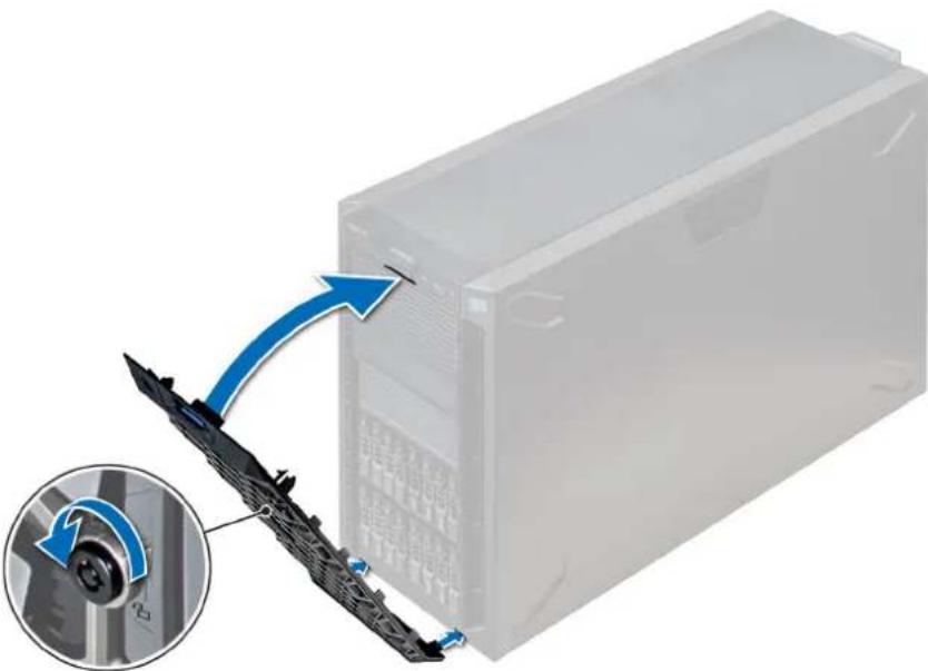
natural_image
Diagram showing a computer tower with a blue arrow pointing to a cable connector, and an inset close-up of the cable being turned (no text or symbols present)Figure 26. Installing the front bezel
System feet
Removing the system feet
Prerequisites

NOTE: It is recommended that you remove the system feet only when you are converting the system from the tower mode to the rack mode, or when you are replacing the system feet with the wheel assembly.
- Follow the safety guidelines listed in Safety instructions.
- Place the system on its side on a flat, stable surface.
- Rotate the system feet inward.
Steps
Using the Phillips #2 screwdriver, remove the screw that secures the foot to the base of the system. a) Repeat the above step for the 3 remaining feet.

natural_image
Exterior view of a server rack with ventilation grilles and connectors, showing a blue arrow pointing to a component (no text or symbols visible)Figure 27. Removing the system feet
Next steps
- Install the system feet or install the castor wheels.
Installing the system feet
Prerequisites

CAUTION: Install the feet on a stand-alone tower system to provide stability to the system. An unstable system might tip over and cause injury to the user or damage to the system.
- Follow the safety guidelines listed in Safety instructions.
- Place the system on its side, on a flat, stable surface.
Steps
- Align the three tabs on the system foot with the three slots on the base of the system.
- Using the Phillips #2 screwdriver, secure the screw that secures the foot to the base of the system.
a) Repeat the above steps to install the remaining system feet.
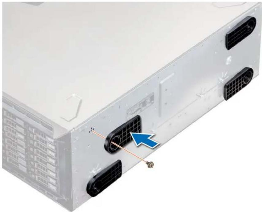
natural_image
Exterior view of a server rack with visible ports and connectors, showing internal components and a blue arrow pointing to a component (no text or symbols)Figure 28. Installing the system feet
Next steps
- Place the system upright on a flat, stable surface, and rotate the system feet outward.
- Follow the procedure listed in After working inside your system.
Caster wheels – optional
Removing caster wheels
Prerequisites
- Follow the safety guidelines listed in Safety instructions.
- Place the system on a flat, stable surface.
Steps
- Using the Phillips #2 screwdriver, loosen the captive screw that secures the front wheel unit to the base of the system.
- Push the front wheel unit toward the rear of the system to release the retention hooks, and pull out the front wheel unit.
- Loosen the screw that secures the back wheel unit to the base of the chassis.
- Push the rear wheel unit toward the front of the system to release the retention hooks, and pull out the rear wheel unit.
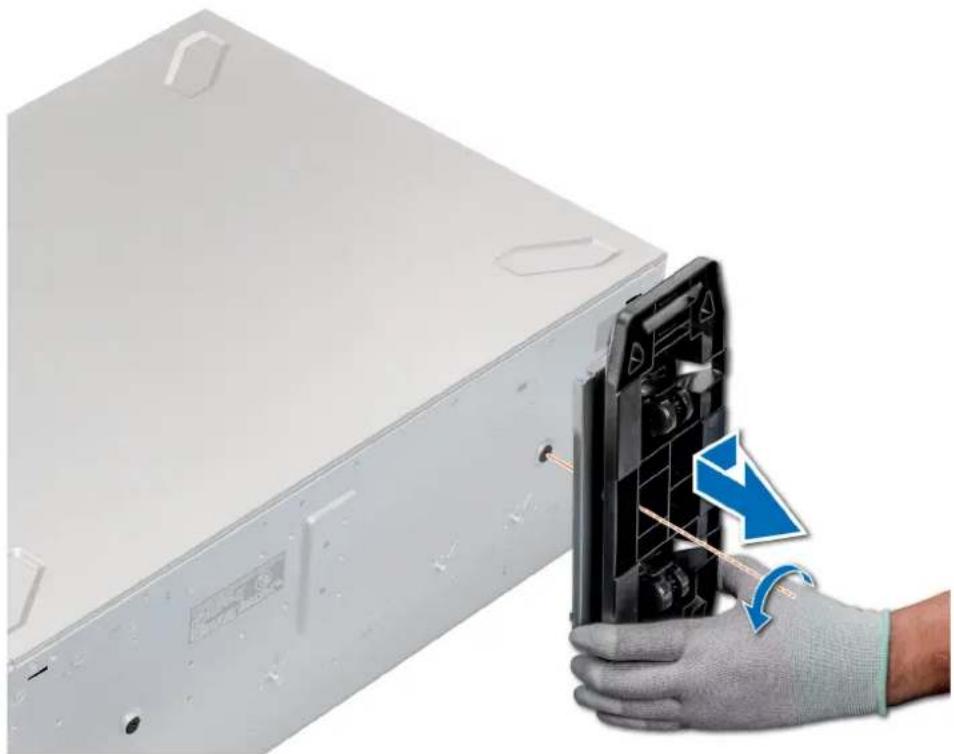
natural_image
Hand holding a device with a blue arrow indicating a disassembly or repair process (no text or symbols visible)Figure 29. Removing caster wheels
Next steps
- Install the caster wheels or the system feet, as applicable.
Installing caster wheels
Prerequisites
- Follow the safety guidelines listed in Safety instructions.
- Place the system on its side on a flat, stable surface.
- If installed, remove the system feet.
Steps
- Align the two retention hooks on the rear wheel unit with the two slots on the base of the system, and insert the hooks into the slots.
- Push the rear wheel unit toward the back of the system and using a Phillips #2 screwdriver secure the unit in place using a single screw.
- Align the two retention hooks on the front wheel unit with the two slots on the base of the system, and insert the hooks into the slots.
- Push the front wheel unit toward the front of the system and using a Phillips #2 screwdriver secure the unit in place using a single screw.
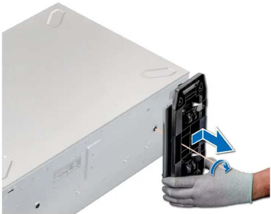
natural_image
Hand holding a device with a blue arrow indicating a change, next to a white server rack (no text or symbols visible)Figure 30. Installing caster wheels
Next steps
- Follow the procedure listed in Before working inside your system.
Drives
Removing a drive blank
The procedure for removing 2.5 inch and 3.5 inch drive blanks is identical.
Prerequisites
- Follow the safety guidelines listed in Safety instructions.
- If installed, remove the front bezel.
CAUTION: To maintain proper system cooling, drive blanks must be installed in all empty drive slots.
CAUTION: Mixing drive blanks from previous generations of PowerEdge servers is not supported.
Steps
Press the release button, and slide the drive blank out of the drive slot.

natural_image
Close-up of a black hard drive housing with a coin slot and blue directional arrows indicating motion (no text or symbols)Figure 31. Removing a drive blank
Next steps
- Install a drive or drive blank.
Installing a drive blank
The procedure for installing 2.5 inch and 3.5 inch drive blanks is identical.
Prerequisites
- Follow the safety guidelines listed in Safety instructions.
- If installed, remove the front bezel.

CAUTION: Mixing drive blanks from previous generations of PowerEdge servers is not supported.
Steps
Insert the drive blank into the drive slot, and push the blank until the release button clicks into place.
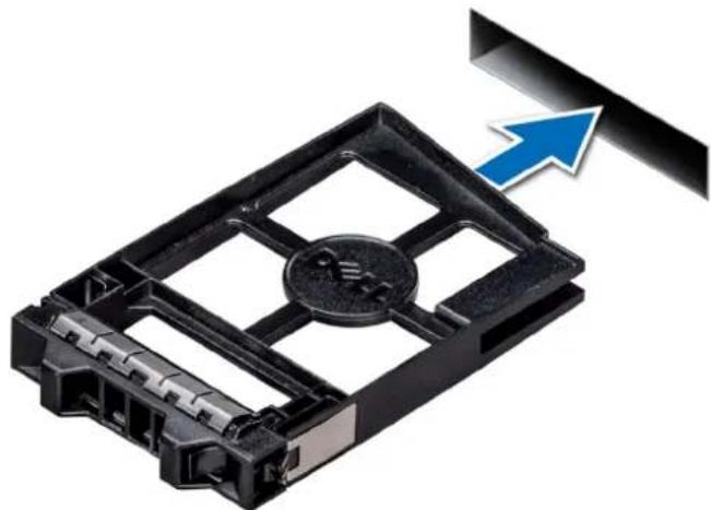
natural_image
Close-up of a black plastic electronic device with a coin slot and arrow indicator (no text or symbols)Figure 32. Installing a drive blank
Next steps
If removed, install the front bezel.
Removing a drive carrier
Prerequisites
- Follow the safety guidelines listed in Safety instructions.
- If applicable, remove the front bezel
- Using the management software, prepare the drive for removal.
If the drive is online, the green activity or fault indicator flashes while the drive is turning off. When the drive indicators are off, the drive is ready for removal. For more information, see the documentation for the storage controller.

CAUTION: Before attempting to remove or install a drive while the system is running, see the documentation for the storage controller card to ensure that the host adapter is configured correctly to support drive removal and insertion.

CAUTION: Mixing drives from previous generations of PowerEdge servers is not supported.

CAUTION: To prevent data loss, ensure that your operating system supports drive installation. See the documentation supplied with your operating system.
Steps
- Press the release button to open the drive carrier release handle.
- Holding the handle, slide the drive carrier out of the drive slot.
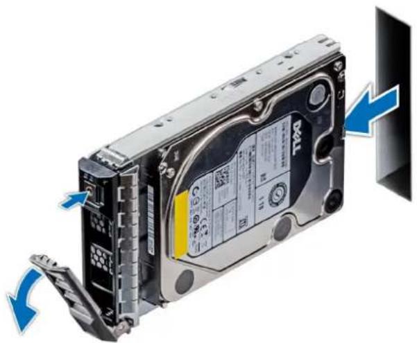
natural_image
Internal view of a TWA hard drive showing internal components and blue directional arrows indicating motion (no text or symbols on the device itself)Figure 33. Removing a drive carrier
Next steps
- Installing a drive carrier.
- If you are not replacing the drive immediately, insert a drive blank in the empty drive slot to maintain proper system cooling.
Installing a drive carrier
Prerequisites

CAUTION: Before attempting to remove or install a drive while the system is running, see the documentation for the storage controller card to ensure that the host adapter is configured correctly to support drive removal and insertion.

CAUTION: Mixing drives from previous generations of PowerEdge servers is not supported.

CAUTION: Combining SAS and SATA drives in the same RAID volume is not supported.
CAUTION: When installing a drive, ensure that the adjacent drives are fully installed. Inserting a drive carrier and attempting to lock its handle next to a partially installed carrier can damage the partially installed carrier's shield spring and make it unusable.
CAUTION: To prevent data loss, ensure that your operating system supports hot-swap drive installation. See the documentation supplied with your operating system.
CAUTION: When a replacement hot swappable drive is installed and the system is powered on, the drive automatically begins to rebuild. Ensure that the replacement drive is blank or contains data that you wish to overwrite. Any data on the replacement drive is immediately lost after the drive is installed.
- Follow the safety guidelines listed in Safety instructions.
- If installed, remove the drive blank.
Steps
- Press the release button on the front of the drive carrier to open the release handle.
- Insert the drive carrier into the drive slot and slide until the drive connects with the backplane.
- Close the drive carrier release handle to lock the drive in place.

natural_image
Internal view of a T30/4 hard disk drive with blue arrow indicating compression (no text or symbols on the device itself)Figure 34. Installing a drive carrier
Next steps
- If removed, install the front bezel.
Removing the drive from the drive carrier
Prerequisites
Follow the safety guidelines listed in Safety instructions.
CAUTION: Mixing drives from previous generations of PowerEdge servers is not supported.
Steps
- Using a Phillips #1 screwdriver, remove the screws from the slide rails on the drive carrier.
- Lift the drive out of the drive carrier.
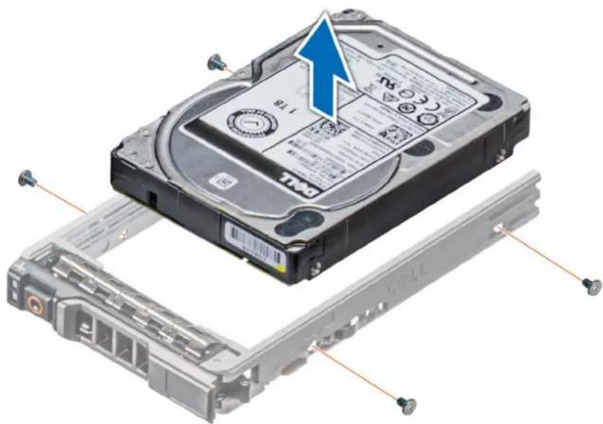
natural_image
Exploded view of a hard disk drive assembly showing internal components and mounting hardware (no text or symbols)Figure 35. Removing the drive from the drive carrier
Next steps
- Installing the drive into the drive carrier.
Installing a drive into the drive carrier
Prerequisites
Follow the safety guidelines listed in Safety instructions.

CAUTION: Mixing drive carriers from other generations of PowerEdge servers is not supported.

NOTE: When installing a drive into the drive carrier, ensure that the screws are torqued to 4 in-lbs.
Steps
- Insert the drive into the drive carrier with the connector end of the drive towards the back of the carrier.
- Align the screw holes on the drive with the screws holes on the drive carrier.
When aligned correctly, the back of the drive is flush with the back of the drive carrier. - Using a Phillips #1 screwdriver, secure the drive to the drive carrier with screws.

natural_image
Exploded view of a hard disk drive assembly showing internal components and mounting hardware (no text or symbols)Figure 36. Installing a drive into the drive carrier
Removing a 3.5 inch drive adapter from a 3.5 inch drive carrier
Prerequisites
- Follow the safety guidelines listed in Safety instructions.
- If installed, remove the front bezel.
- Remove the drive carrier.
Steps
- Using a Phillips #1 screwdriver, remove the screws from the rails on the drive carrier.
- Lift the 3.5 inch drive adapter out of the 3.5 inch drive carrier.
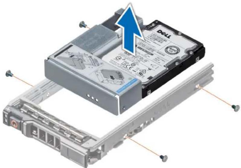
natural_image
3D illustration of a Dell drive assembly showing internal components and cable connections (no text or symbols)Figure 37. Removing a 3.5 inch drive adapter from a 3.5 inch drive carrier
Next steps
- Install the 3.5 inch drive adapter into the 3.5 inch drive carrier
Installing a 3.5 inch drive adapter into the 3.5 inch drive carrier
Prerequisites
- Follow the safety guidelines listed in Safety instructions.
- Install the 2.5 inch drive into the 3.5 inch drive adapter.
Steps
- Insert the 3.5 inch drive adapter into the 3.5 inch drive carrier with the connector end of the drive toward the back of the 3.5 inch drive carrier.
- Align the screw holes on the 3.5 inch drive adapter with the holes on the 3.5 inch drive carrier.
- Using a Phillips #1 screwdriver, secure the 3.5 inch drive adapter to the 3.5 inch carrier.
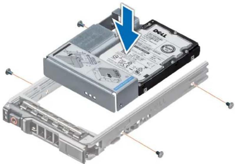
natural_image
3D illustration of a Dell drive chassis with a blue arrow indicating a component, showing internal components and mounting hardware (no text or symbols)Figure 38. Installing a 3.5 inch drive adapter into the 3.5 inch drive carrier
Next steps
- Install the drive carrier.
- If removed, install the front bezel.
Removing a 2.5 inch drive from a 3.5 inch drive adapter
Prerequisites
- Follow the safety guidelines listed in Safety instructions.
- Remove the 3.5 inch drive adapter from the 3.5 inch drive carrier.

NOTE: A 2.5 inch drive is installed in a 3.5 inch drive adapter, which is then installed in the 3.5 inch drive carrier.
Steps
- Using a Phillips #2 screwdriver, remove the screws from the side of the 3.5 inch drive adapter.
- Remove the 2.5 inch drive from the 3.5 inch drive adapter.
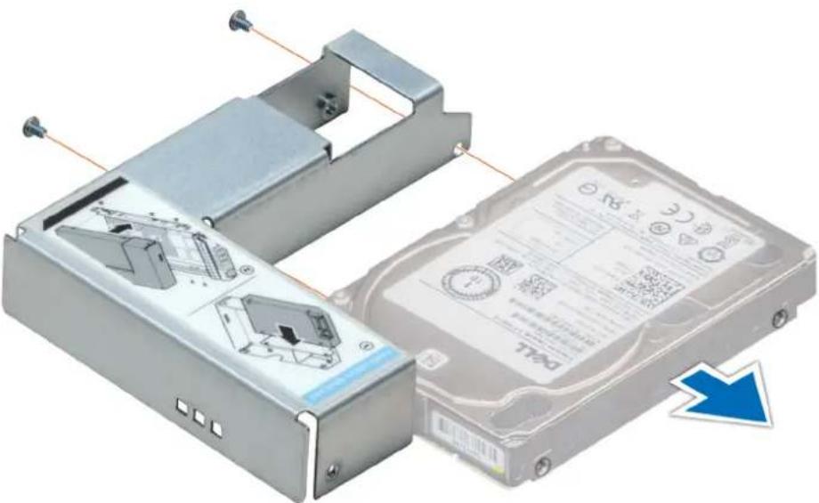
natural_image
3D diagram of a mechanical device showing internal components and assembly, with no visible text or symbols.Figure 39. Removing a 2.5 inch drive from a 3.5 inch drive adapter
Next steps
Install a 2.5 inch drive into a 3.5 inch drive adapter.
Installing a 2.5 inch drive into a 3.5 inch drive adapter
Prerequisites
- Follow the safety guidelines listed in Safety instructions.
- Remove the 3.5 inch drive adapter from the 3.5 inch hot swappable drive carrier.
Steps
- Align the screw holes on the 2.5 inch drive with the screw holes on the 3.5 inch drive adapter.
- Using a Phillips #2 screwdriver, secure the 2.5 inch drive to the 3.5 inch drive adapter.
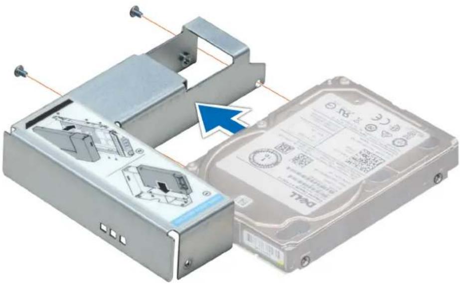
natural_image
3D diagram of a mechanical device with internal components and a blue arrow indicating a specific part (no text or symbols present)Figure 40. Installing a 2.5 inch drive into a 3.5 inch drive adapter
Next steps
- Install the 3.5 inch drive adapter into the 3.5 inch hot swappable drive carrier.
Power supply units
PSU specifications
The power supply unit (PSU) is an internal hardware component which supplies power to the components in the system.
Your system supports one of the following:
- Two 2400 W, 2000 W, 1600 W, 1100 W, 750 W, or 495 W AC PSUs
- Two 750 W Mixed Mode HVDC PSUs
NOTE: For more information, see the Technical specifications section.
CAUTION: If two PSUs are installed, both the PSUs must have the same type of label. For example, Extended Power Performance (EPP) label. Mixing PSUs from previous generations of PowerEdge servers is not supported, even if the PSUs have the same power rating. Mixing PSUs will result in mismatch condition or failure to turn the system on.
NOTE: Titanium PSU is nominally rated for 200 V AC to 240 V AC input only.
NOTE: When two identical PSUs are installed, power supply redundancy (1+1 – with redundancy or 2+0 – without redundancy) is configured in system BIOS. In redundant mode, power is supplied to the system equally from both PSUs when Hot Spare is disabled. When Hot Spare is enabled, one of the PSUs is put into the sleep mode when system utilization is low in order to maximize efficiency.
NOTE: If two PSUs are used, they must be of the same maximum output power.
Hot spare feature
Your system supports the hot spare feature that significantly reduces the power overhead associated with power supply unit (PSU) redundancy.
When the hot spare feature is enabled, one of the redundant PSUs is switched to the sleep state. The active PSU supports 100 percent of the system load, thus operating at higher efficiency. The PSU in the sleep state monitors output voltage of the active PSU. If the output voltage of the active PSU drops, the PSU in the sleep state returns to an active output state.
If having both PSUs active is more efficient than having one PSU in the sleep state, the active PSU can also activate the sleeping PSU.
The default PSU settings are as follows:
- If the load on the active PSU is more than 50 percent of PSU rated power wattage, then the redundant PSU is switched to the active state.
- If the load on the active PSU falls below 20 percent of PSU rated power wattage, then the redundant PSU is switched to the sleep state.
You can configure the hot spare feature by using the iDRAC settings. For more information, see the iDRAC User's Guide available at Dell.com/idracmanuals.
Removing a power supply unit blank
Prerequisites
Follow the safety guidelines listed in Safety instructions.
Steps
If you are installing a second power supply unit, remove the power supply unit blank in the bay by pulling the blank outward.

CAUTION: To ensure proper system cooling, the power supply unit blank must be installed in the second power supply unit bay in a non-redundant configuration. Remove the power supply unit blank only if you are installing a second power supply unit.

natural_image
3D diagram of a mechanical component with blue arrows indicating direction, showing internal structure and housing (no text or symbols)Figure 41. Removing a power supply unit blank
Next steps
- Install the power supply unit blank.
Installing a power supply unit blank
Prerequisites
- Follow the safety guidelines listed in Safety instructions.

NOTE: Install the power supply unit (PSU) blank only in the second PSU bay.
Steps
Align the PSU blank with the PSU slot and push it into the PSU slot until it clicks into place.
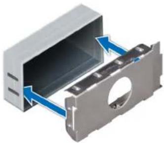
natural_image
3D diagram of a mechanical component with blue arrows indicating direction, showing internal structure and housing (no text or symbols)Figure 42. Installing a power supply unit blank
Next steps
- Follow the procedure listed in After working inside your system.
Removing a AC power supply unit
Prerequisites

CAUTION: The system needs one power supply unit (PSU) for normal operation. On power-redundant systems, remove and replace only one PSU at a time in a system that is powered on.
- Follow the safety guidelines listed in Safety instructions.
- Disconnect the power cable from the power source and from the PSU you intend to remove, and then remove the cable from the strap on the PSU handle.
Steps
Press the orange release latch and slide the PSU out of the system by using the PSU handle.
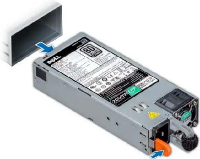
text_image
341 80 2000W/EP+ ↓Figure 43. Removing a power supply unit
Next steps
- Install the AC PSU.
Installing a AC power supply unit
Prerequisites
- Follow the safety guidelines listed in Safety instructions.
- For systems that support redundant PSU, ensure that both the PSUs are of the same type and have the same maximum output power.
NOTE: The maximum output power (shown in watts) is listed on the PSU label.
Steps
Slide the PSU into the system until the PSU is fully seated and the release latch snaps into place.
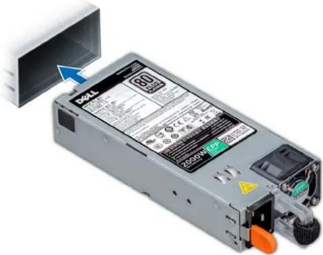
text_image
BZL 80 1000W/EPFigure 44. Installing a power supply unit
Next steps
- Connect the power cable to the PSU, and plug the cable into a power outlet.
CAUTION: When connecting the power cable to the PSU, secure the cable to the PSU with the strap.
NOTE: When installing, hot swapping, or hot adding a new PSU, wait for 15 seconds for the system to recognize the PSU and determine its status. The PSU redundancy may not occur until discovery is complete. Wait until the new PSU is discovered and enabled before you remove the other PSU. The PSU status indicator turns green to signify that the PSU is functioning properly.
Removing a DC power supply unit
Prerequisites
NOTE: For equipment using –(48–60) V DC power supply units (PSUs), a qualified electrician must perform all connections to DC power and to safety grounds. Do not attempt connecting to DC power or installing grounds yourself. All electrical wiring must comply with applicable local or national codes and practices. Damage due to servicing that is not authorized by Dell is not covered by your warranty. Read and follow all safety instructions that came with the product.
CAUTION: The system needs one PSU for normal operation. On power-redundant systems, remove and replace only one PSU at a time in a system that is powered on.
- Follow the safety guidelines listed in Safety instructions.
-
Disconnect the power wires from the power source and the connector from the PSU you intend to remove.
-
Disconnect the safety ground wire.
Steps
Press the release latch and slide the PSU out of the system by using the PSU handle.
Next steps
- Install the DC PSU.
Installing DC power supply unit
Prerequisites
NOTE: For equipment using - (48-60) V DC power supply units (PSUs), a qualified electrician must perform all connections to DC power and to safety grounds. Do not attempt connecting to DC power or installing grounds yourself. All electrical wiring must comply with applicable local or national codes and practices. Damage due to servicing that is not authorized by Dell is not covered by your warranty. Read and follow all safety instructions that came with the product.
- Follow the safety guidelines listed in Safety instructions.
- For systems that support redundant power supply units (PSUs), ensure that both the PSUs are of the same type and have the same maximum output power.
NOTE: The maximum output power (shown in watts) is listed on the PSU label.
Steps
Slide the PSU into the system until the PSU is fully seated and the release latch snaps into place.
Next steps
- Connect the safety ground wire.
- Install the DC power connector in the PSU.
CAUTION: When connecting the power wires, ensure that you secure the wires with the strap to the PSU handle.
- Connect the wires to a DC power source.
NOTE: When installing, hot-swapping, or hot-adding a new PSU, wait for 15 seconds for the system to recognize the PSU and determine its status. The PSU status indicator turns green to signify that the PSU is functioning properly.
Wiring instructions for a DC power supply unit
Your system supports up to two - (48-60) V DC power supply units (PSUs).
NOTE: For equipment using –(48–60) V DC power supply units (PSUs), a qualified electrician must perform all connections to DC power and to safety grounds. Do not attempt connecting to DC power or installing grounds yourself. All electrical wiring must comply with applicable local or national codes and practices. Damage due to servicing that is not authorized by Dell is not covered by your warranty. Read and follow all safety instructions that came with the product.
CAUTION: Wire the unit with copper only, unless otherwise specified, use only 10 American Wire Gauge (AWG) wire rated minimum 90°C for source and return. Protect the -(48-60) V DC (1 wire) with a branch circuit over-current protection rated 50 A for DC with a high interrupt current rating.
CAUTION: Connect the equipment to a -(48-60) V DC supply source that is electrically isolated from the AC source (reliably grounded -(48-60) V DC SELV source). Ensure that the -(48-60) V DC source is efficiently secured to earth (ground).
NOTE: A readily accessible disconnect device that is suitably approved and rated shall be incorporated in the field wiring.
Input requirements
• Supply voltage: -(48-60) V DC
- Current consumption: 32 A (maximum)
Kit contents
- Dell part number 6RYJ9 terminal block or equivalent (1)
-
6-32 nut equipped with lock washer (1)
Required tools
Wire-stripper pliers capable of removing insulation from size 10 AWG solid or stranded, insulated copper wire.

NOTE: Use alpha wire part number 3080 or equivalent (65/30 stranding).
Required wires
- One UL 10 AWG, 2 m maximum (stranded) black wire [-(48-60) V DC].
• One UL 10 AWG, 2 m maximum (stranded) red wire (V DC return). - One UL 10 AWG, 2 m maximum, green with a yellow stripe, stranded wire (safety ground).
System cover
Removing the system cover
Prerequisites
- Follow the safety guidelines listed in Safety instructions.
- Turn off the system and all attached peripherals.
- Disconnect the system from the electrical outlet and peripherals.
- If installed, remove the front bezel.
- Place the system on a flat, stable surface.
Steps
- Turn the latch release lock to the unlocked position.
- Press the cover release latch and remove the system cover.

natural_image
Diagram of a computer tower with an attached cable, showing the base panel and internal components (no text or symbols)Figure 45. Removing the system cover
Next steps
- Install the system cover.
Installing the system cover
Prerequisites

NOTE: Ensure that all internal cables are connected and placed out of the way and no tools or extra parts are left inside the system.
Follow the safety guidelines listed in Safety instructions.
Steps
- Align the tabs on the system cover with the slots on the chassis.
- Press the cover release latch, and push the cover toward the chassis until the latch locks into place.
- Rotate the latch release lock clockwise to the locked position.

natural_image
Diagram of a computer tower with a cable inserted into a drive, showing a close-up view of the internal components (no text or symbols present)Figure 46. Installing the system cover
Next steps
- Place the system upright on its feet on a flat and stable surface.
- If removed, install the front bezel.
- Reconnect the peripherals and connect the system to the electrical outlet.
- Turn on the system, including all attached peripherals.
Inside the system
NOTE: Components that are hot swappable are marked orange and touch points on the components are marked blue.
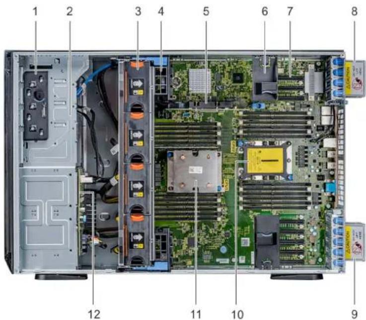
text_image
1 2 3 4 5 6 7 8 12 11 10 9- Release latch 2. Drive cage
- Hot-swappable fans (middle fans) 4. GPU card holder
-
Internal PERC 6. PCIe card holder
-
PCIe slots 8. Left external fan
- Right external fan 10. CPU2 socket
- CPU1 12. Backplane
Air shroud
Removing the optional GPU air shrouds
Prerequisites

CAUTION: Never operate your system with the air shroud removed. The system may get overheated quickly, resulting in shutdown of the system and loss of data.
- Follow the safety guidelines listed in Safety instructions.
- Follow the procedure listed in Before working inside your system.
Steps
Holding the touch points, press the release latch and lift the shroud out.

natural_image
3D rendering of a server rack with black plastic components and blue upward arrows indicating airflow or heat transfer (no text or symbols)Figure 47. Removing the optional GPU air shrouds
Next steps
- Install the optional GPU air shrouds.
Installing the optional GPU air shrouds
Prerequisites
Follow the safety guidelines listed in Safety instructions.
Steps
- Align the tabs on the GPU air shroud with the securing slots on the chassis.
- Lower the GPU air shroud into the chassis until it is firmly seated.
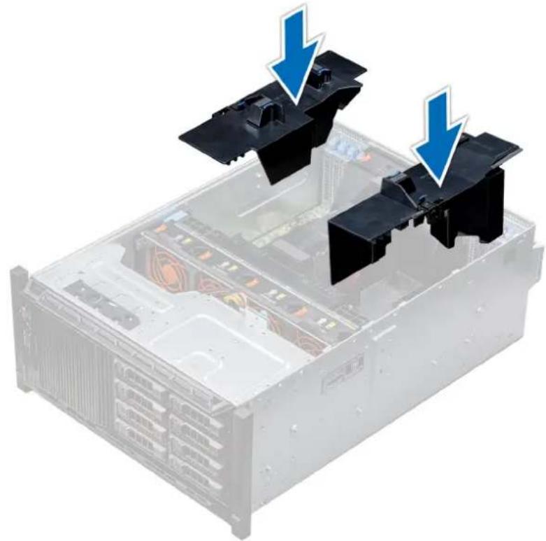
natural_image
3D rendering of a server rack with two black plastic components and blue arrows indicating downward motion (no text or symbols)Figure 48. Installing the optional GPU air shrouds
Next steps
Follow the procedure listed in After working inside your system.
Removing the air shroud
Prerequisites

CAUTION: Never operate your system with the air shroud removed. The system may get overheated quickly, resulting in shutdown of the system and loss of data.
- Follow the safety guidelines listed in Safety instructions.
- Follow the procedure listed in Before working inside your system.
- If required, remove the two fans from the air shroud.

NOTE: The procedure to remove the cooling fan from the air shroud is similar to removing a cooling fan.
Steps
Push the air shroud release tab, and holding the touch points at the center of the air shroud, lift the shroud from the system.
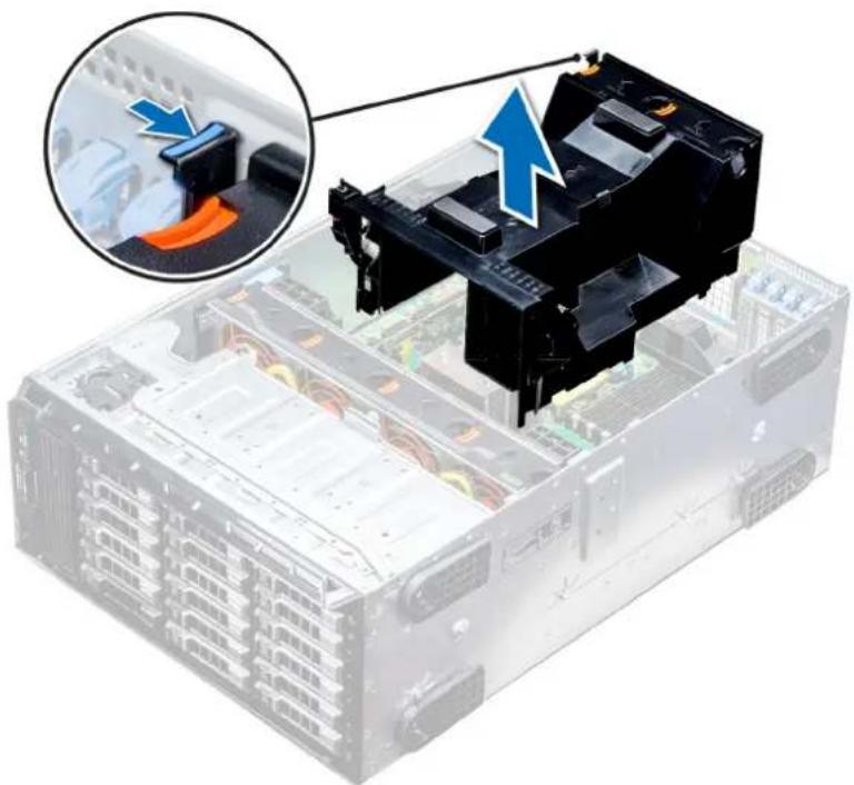
natural_image
Illustration of a server rack with an attached black battery component, showing internal components and a magnified inset of the device (no text or symbols visible)Figure 49. Removing the air shroud
Next steps
- Install the air shroud.
Installing the air shroud
Prerequisites
- Follow the safety guidelines listed in Safety instructions.
- If applicable, route the cables inside the system along the chassis wall and secure the cables by using the cable-securing bracket.
Steps
- Align the tabs on the air shroud with the securing slots on the chassis.
a) Guide on the air shroud with the guide pin on the system board.
b) Align the intrusion switch with the intrusion switch connector on the system board.
- Lower the air shroud into the chassis until it is firmly seated.
When firmly seated, the memory socket numbers marked on the air shroud align with the respective memory sockets.
3.
NOTE: The procedure to install the cooling fan into the air shroud is similar to installing a cooling fan.
If removed, install the fans into the air shroud.
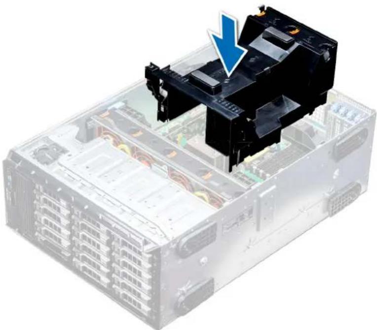
natural_image
3D illustration of a server rack with an open black device and a blue arrow pointing to it, indicating a process or operation (no text or symbols present)Figure 50. Installing the air shroud
Next steps
- Follow the procedure listed in After working inside your system.
Cooling fans
Cooling fan specifications
The cooling fans are integrated into the system to dissipate the heat generated by the functioning of the system. These fans provide cooling for the processors, expansion cards, and memory modules.
Your system supports a total of eight fans, including six hot-swappable fans and two external fans. Two hot-swappable fans are mounted in rear side of the air shroud. The other four hot-swappable (middle) fans are mounted in the fan assembly that is located in the chassis between the hard drive bay and the processors. The two external fans are mounted on the outside of the chassis for GPU configurations. There are two additional fans integrated in the power supplies to cool the power supplies and provide additional cooling for the whole system.
The below listed configurations, features, and the PCIe expansion cards are supported only with the four hot-swappable (middle) fans installed:
- Fan redundancy
- Fresh air condition
• NVMe/PCIe SSD - 3.5 inch x 18 hard drives chassis
• Mellanox CX4 DP 100 Gb QSFP NIC (0272F) - Mellanox CX4 DP 100 Gb NIC (068F2)
- Mellanox CX4 SP 100 Gb NIC (6W1HY)
- Mellanox DP 40 Gb QSFP NIC (C8Y42)
- Intel QP 10 Gb Base-T NIC (K5V44)
• Solarflare Sunspot DP 10Gb NIC (NPHCM)
• Solarflare Nova DP 10Gb NIC (WY7T5)
• Qlogic DP 10Gb V1 NIC (VCXN5)
Listed below are the restrictions for fan redundancy:
- GPGPU configurations are not supported at 35deg. C of ambient or above.
- Mellanox 100G NICs are not supported.
For information on the restriction for fresh air condition, see the Expanded operating temperature restrictions topic in the Technical Specification section.
Cooling fan matrix
| Chassis FAN1, FAN2 (Standard [STD]) | FAN3, FAN4, FAN5, FAN6 (Standard [STD]/High performance [HPR]) | FAN_EXT_R, FAN_EXT_L | Fan configuration |
3.5 inch x 8 Yes -- Base configuration
3.5 inch x 18 Yes Yes (STD) - Rich configuration
2.5 inch x 16 Yes - - Base configuration
2.5 inch x 32 Yes -- Base configuration
2.5 inch x 16 + NVMe Yes Yes (STD) - Rich configuration
Fan redundancy, FA and high cooling tier PCIe card Yes Yes (STD) - Rich configuration
GPGPU card Yes Yes (HPR) Yes GPU configuration
Removing a middle or rear cooling fan
The procedure for removing a standard and a high performance fans is identical.
Prerequisites

NOTE: Opening or removing the system cover when the system is on may expose you to a risk of electric shock. Exercise utmost care while removing or installing cooling fans.

CAUTION: The cooling fans are hot swappable. To maintain proper cooling while the system is on, replace only one fan at a time.
- Follow the safety guidelines listed in Safety instructions.
- Follow the procedure listed in Before working inside your system.
Steps
Press the release tab and lift the cooling fan out of the cooling fan assembly.

natural_image
Interior view of a server rack with a hand inserting a device into the case (no text or symbols visible)Figure 51. Removing a middle cooling fan
Next steps
- Installing a middle or rear cooling fan.
Installing a middle or rear cooling fan
The procedure for installing a standard and a high performance fans is identical.
Prerequisites

NOTE: Opening or removing the system cover when the system is on may expose you to a risk of electric shock. Exercise utmost care while removing or installing cooling fans.

CAUTION: The cooling fans are hot swappable. To maintain proper cooling while the system is on, replace only one fan at a time.
- Follow the safety guidelines listed in Safety instructions.
- Follow the procedure listed in Before working inside your system.
Steps
Holding the release tab, align the connector at the base of the cooling fan with the connector on the system board.

natural_image
Hand installing a CD drive into a server rack (no text or symbols visible)Figure 52. Installing a middle cooling fan
Next steps
- Follow the procedure listed in After working inside your system.
Removing the right external fan
Prerequisites
NOTE: Opening or removing the system cover when the system is on may expose you to a risk of electric shock. Exercise utmost care while removing or installing cooling fans.
NOTE: The procedure to remove the left external fan is similar to removing the right rear fan.
- Follow the safety guidelines listed in Safety instructions.
- Remove the GPU air shrouds.
- Remove the air shroud.
Steps
- Disconnect the fan cable from the system board.
- Using the Phillips #2 screwdriver, loosen the captive screws that secure the fan to the system.
- Lift the fan away, while guiding the fan cable through the cable vent.

natural_image
Illustration of a server rack with a hand holding a device, showing a close-up of the rack and a magnified inset highlighting a component (no text or symbols present)Figure 53. Removing the right external fan
Next steps
- Installing the right external fan.
Installing the right external fan
Prerequisites
NOTE: The procedure to install the left external fan is similar to installing the right rear fan.
Follow the safety guidelines listed in Safety instructions.
Steps
- Guiding the fan cable through the cable vent, install the external fan over the PCIe slots.
- Using the Phillips #2 screwdriver, secure the fan in place.
- Connect the fan cable to the connected on the system board.

natural_image
Close-up of a hand using a tool to adjust or install electronic components on a computer motherboard, with no visible text or symbols.Figure 54. Install the right external fan
Next steps
- Install the air shroud.
- Install the GPU air shrouds.
- Follow the procedure listed in After working inside your system.
- Follow the safety guidelines listed in Safety instructions.
- Follow the procedure listed in Before working inside your system.
Steps
- Lift the release levers to unlock the cooling fan assembly from the system.
- Hold the release levers, and lift the cooling fan assembly away from the system.
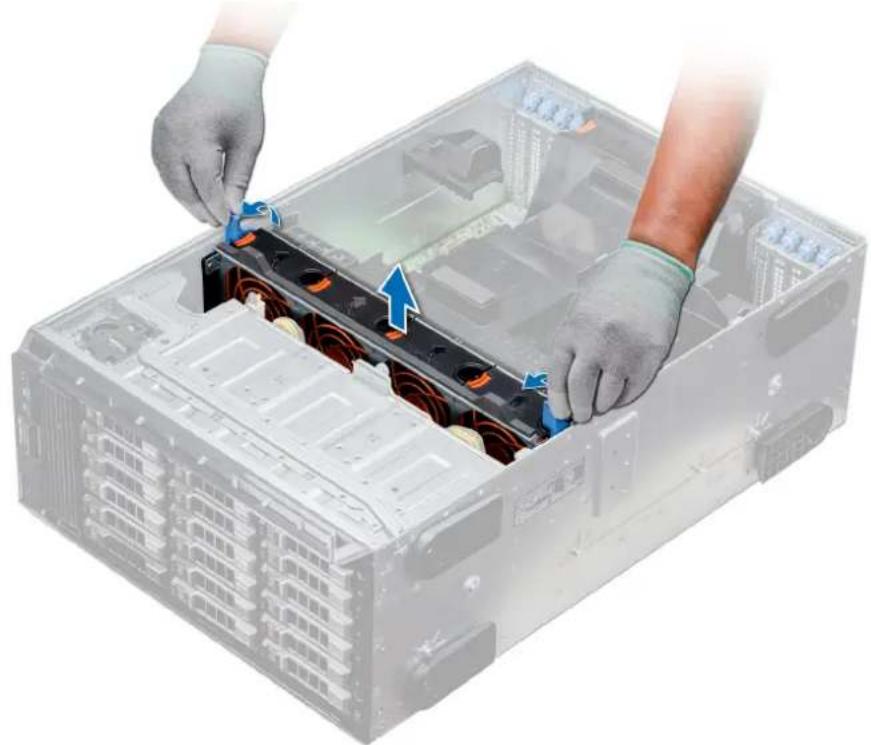
natural_image
Illustration of hands installing or adjusting a server rack component with blue arrows indicating movement (no text or symbols present)Figure 55. Removing the middle cooling fan assembly
Next steps
- Installing the middle cooling fan assembly.
Installing the middle cooling fan assembly
Prerequisites
Follow the safety guidelines listed in Safety instructions.

CAUTION: Ensure that the cables inside the system are correctly installed and retained by the cable retention bracket before installing the cooling fan assembly. Incorrectly installed cables may get damaged.
Steps
- Align the guide rails on the cooling fan assembly with the standoffs on the system.
-
Lower the cooling fan assembly into the system until the cooling fan connectors engage with the connectors on the system board.
-
Press the release levers to lock the cooling fan assembly into the system.

natural_image
Person installing or adjusting a server rack component with blue arrows indicating motion (no text or symbols visible)Figure 56. Installing the middle cooling fan assembly
Next steps
- Follow the procedure listed in After working inside your system.
Flex bays
Removing a NVMe drive bay or flex bay
Prerequisites
NOTE: The procedure to remove the flex bay is identical to removing the NVMe drive bay.
- Follow the safety guidelines listed in Safety instructions.
- Follow the procedure listed in Before working inside your system.
- Disconnect the slim optical-drive and the backplane cables.
- Remove the backplane from NVMe drive bay or the flex bay.
Steps
- Using the Phillips #2 screwdriver, remove the two screws that secure the NVMe drive bay to the system.
- Push the release latch down and slide the NVMe drive bay out of the system.

natural_image
Illustration of a server rack with multiple drive bays and a blue directional arrow indicating compression (no text or symbols)Figure 57. Removing a NVMe drive bay or flex bay
Next steps
- Installing the NVMe drive bay or flex bay.
Installing a NVMe drive bay or flex bay
Prerequisites
NOTE: The procedure to install the flex bay is identical to installing the NVMe drive bay.
Follow the safety guidelines listed in Safety instructions.
Steps
- Align the tabs on the NVMe drive bay with the slots on the front of the system.
- Insert the NVMe drive bay into the system until the tabs click into place.
- Using the Phillips #2 screwdriver secure the NVMe drive bay to the system.

natural_image
Illustration of a server rack with multiple drive bays and attached hardware unit (no text or symbols visible)Figure 58. Installing a NVMe drive bay or flex bay
Next steps
- Install the backplane to the NVMe drive bay or flex bay.
- Connect the slim optical drive and the back plane cables.
- Follow the procedure listed in After working inside your system.
Optical drives and tape drives
Optical drives and tape drives specifications
Your system supports one of the following configurations:
Table 34. System configurations
System Configurations
| Eight 3.5 inch drives or sixteen 2.5 inch drives Up to two SATA slim optical drives and one SAS tape drive |
| Sixteen 2.5 inch drives and eight NVMe drives One SATA slim optical drive |
| Systems with up to eighteen 3.5 inch drives One SATA slim optical drive or one SAS tape drive |
| Systems with up to thirty-two 2.5 inch drives One SATA slim optical drive |
Removing the optical or tape drive blank
Prerequisites
- Follow the safety guidelines listed in Safety instructions.
- Follow the procedure listed in Before working inside your system.
- If installed, remove the front bezel.
Steps
-
To remove the drive blank, slide the release latch down to release the drive blank.
-
Push the drive blank to slide it out of the drive bay.

NOTE: Blanks must be installed on empty optical drive or tape drive slots to maintain FCC certification of the system. The brackets also keep dust and dirt out of the system and aid in proper cooling and airflow inside the system. Perform the same steps to install blanks.
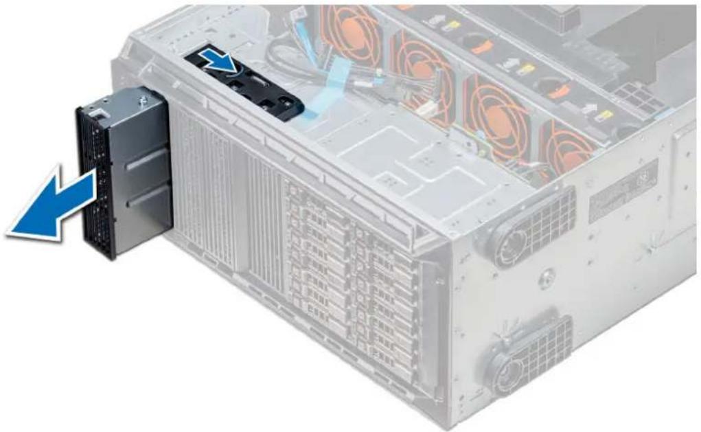
natural_image
Exterior view of a server rack with a highlighted drive unit and blue arrow indicating direction (no text or symbols)Figure 59. Removing the optical drive or tape drive
Next steps
- Install theoptical drive blank, an optical drive, or a tape drive.
Installing the optical or tape drive blank
Prerequisites
- Follow the safety guidelines listed in Safety instructions.
- If installed, remove the front bezel.
Steps
-
Align the guide on the drive blank with the slot on drive bay.
-
Slide the drive into the slot until the latch snaps into place.

natural_image
Illustration of a server rack with a highlighted drive unit and cable spool, showing internal components without any text or symbols.Figure 60. Installing the optical or tape drive blank
Next steps
- If removed, install the front bezel.
- Follow the procedure listed in After working inside your system.
Removing the optical drive cage or tape drive
Prerequisites
NOTE: The procedure to remove the optical drive cage is identical to removing a tape drive.
- Follow the safety guidelines listed in Safety instructions.
- Follow the procedure listed in Before working inside your system.
- If installed, remove the front bezel.
Steps
- Disconnect the power and data cable from the back of the drive.
NOTE: Observe the routing of the power and data cable inside the chassis as you remove them from the system board and the drive. You must route these cables properly when you replace them to prevent them from being pinched or crimped.
- To remove the drive, push the release latch to release the drive.
- Slide the drive out of the drive bay.
- If you are not immediately replacing the tape drive, install the blank.
NOTE: Blanks must be installed on empty optical drive or tape drive slots to maintain FCC certification of the system. The brackets also keep dust and dirt out of the system and aid in proper cooling and airflow inside the system. Perform the same steps to install blanks.
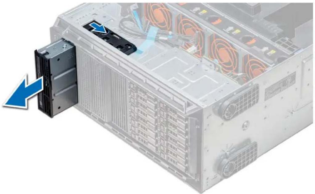
natural_image
Illustration of a server rack with an attached drive unit and a blue arrow indicating a loading or disassembly process (no text or symbols present)Figure 61. Removing the optical drive cage or tape drive
Next steps
- Install the optical drive cage or tape drive.
Installing the optical drive cage or tape drive
Prerequisites
NOTE: The procedure to install the optical drive cage is the same as installing the tape drive.
Follow the safety guidelines listed in Safety instructions.
Steps
- Unpack and prepare the drive for installation.
For instructions, see the documentation that shipped with the drive.
If you are installing a SAS tape drive, you must have an internal tape adapter installed. For more information on installing a SAS tape drive, see the Installing an expansion card section.
- If applicable, remove the existing drive or the drive blank.
- Align the guide on the drive with the slot on drive bay.
- Slide the drive into the slot until the latch clicks into place.
- Connect the power and data cable to the drive.
- Connect the power and data cables to the backplane and the system board.

natural_image
Illustration of a server rack with a highlighted drive component (no text or symbols visible)Figure 62. Installing the optical drive cage or tape drive
Next steps
- If removed, install the front bezel.
- Follow the procedure listed in After working inside your system.
Removing the slim optical drive
The procedure to remove the slim optical drive blank is similar to removing the slim optical drive.
Prerequisites
- Follow the safety guidelines listed in Safety instructions.
- Follow the procedure listed in Before working inside your system.
- Remove the optical drive cage.

NOTE: The procedure to remove the optical drive cage is identical to removing the optical or tape drive blank.
Steps
- Locate the touch point for the slim optical drive lock on the cage.
- Press the lock and push the slim optical drive out of the cage.

natural_image
Two electronic drive units with a blue arrow indicating a component or connection (no text or symbols visible)Figure 63. Removing the slim optical drive blank
Next steps
- Install the slim optical drive or the optical drive blank.
Installing the slim optical drive
The procedure to install the optical drive blank is similar to installing the slim optical drive.
Prerequisites
Follow the safety guidelines listed in Safety instructions.
Steps
- Align the slim optical drive with the slim optical drive bay on the optical drive cage.
- Slide the optical drive into the optical drive bay until the lock clicks into place.
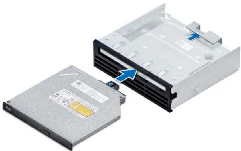
natural_image
Two electronic drive units with a blue arrow indicating a component, one showing a physical appearance (no text or symbols visible)Figure 64. Installing the slim optical drive blank
Next steps
- Install the optical drive cage.
- Follow the procedure listed in After working inside your system.
NVDIMM-N battery
Removing the NVDIMM-N battery
Prerequisites
- Follow the safety guidelines listed in Safety instructions.
- Follow the procedure listed in Before working inside your system.

CAUTION: To prevent data loss, ensure that your system is turned off and that the indicator LEDs on the battery are Off before removing the NVDIMM-N battery.

CAUTION: To avoid damage to the battery connector, you must firmly support the connector while installing or removing a battery.
- Remove the NVDIMM-N battery cage.
Steps
- Disconnect the cables from the NVDIMM-N battery.
- Using the Phillips #2 screwdriver, loosen the screw securing the NVDIMM-N battery.
- Holding the edges, lift the battery from the NVDIMM-N battery cage.

natural_image
Internal view of an electronic device with a black circuit breaker and indicator lights, showing a blue upward arrow (no text or symbols on the device itself)Figure 65. Removing the NVDIMM-N battery
Next steps
- Install the NVDIMM-N battery.
Installing the NVDIMM-N battery
Prerequisites

CAUTION: To avoid damage to the battery connector, you must firmly support the connector while installing or removing a battery.
Follow the safety guidelines listed in Safety instructions.
Steps
- Install the NVDIMM-N battery into the battery cage
- Using the Phillips #2 screwdriver, tighten the screw to secure the NVDIMM-N battery.
- Connect the cables to the NVDIMM-N battery.
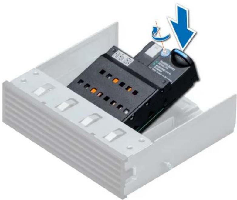
natural_image
Interior view of an electronic device with a black circuit breaker and a blue downward arrow indicating a warning or adjustment (no text or symbols present)Figure 66. Installing the NVDIMM-N battery
Next steps
- Install the NVDIMM-N battery cage.
- Follow the procedure listed in After working inside your system.
System memory
System memory guidelines
The PowerEdge systems support DDR4 Registered DIMMs (RDIMMs), Load Reduced DIMMs (LRDIMMs), and Non-Volatile DIMMs (NVDIMM-Ns). System memory holds the instructions that are executed by the processor.
Your system contains 24 memory sockets split into two sets of 12 sockets, one set per processor. Each 12-socket set is organized into six channels. Six memory channels are allocated to each processor. In each channel, the release tabs of the first socket are marked white, and the second socket black.
Memory channels are organized as follows:

text_image
B9 B8 B7 B3 B2 B1 B4 B5 B6 B10 B11 B12 A6 A5 A4 A12 A11 A10 A7 A8 A9 A1 A2 A3Figure 67. System memory view
Table 35. Memory channels
Proces Channel 0 Channel 1 Channel 2 Channel 3 Channel 4 Channel 5 sor
| Proces sor 1 | Slots A1 and A7 Slots A2 and A8 Slots A3 and A9 Slots A4 and A10 Slots A5 and A11 Slots A6 and A12 |
| Proces sor 2 | Slots B1 and B7 Slots B2 and B8 Slots B3 and B9 Slots B4 and B10 Slots B5 and B11 Slots B6 and B12 |
The following table shows the memory populations and operating frequencies for the supported configurations:
Table 36. Memory population
| DIMM Type DIMMs Populated/ Channel | Voltage | Operating Frequency (in MT/s) | Maximum DIMM Rank/ Channel |
| RDIMM 1 | 2933, 2666, 2400, 2133 Dual rank or single rank | ||
| 1.2 V | |||
| 2 2666, 2400, 2133 Dual rank or single rank | |||
| LRDIMM 1 | 2933, 2666, 2400, 2133 Quad rank | ||
| 1.2 V | |||
| 2 2666, 2400, 2133 Quad rank | |||
| NVDIMM-N 1 | 1.2 V | 2933, 2666, 2400, 2133 Single rank | |
NVDIMM population rules
• Maximum of one NVDIMM per channel.
• Maximum of six NVDIMMs per processor
• Maximum capacity per NVDIMM is 16GB
NVDIMMs are not supported on the following configurations:
- 32 x 2.5-inch SAS/SATA/SSD drive configuration
- 16 x 2.5-inch SAS/SATA/SSD drives with 8 x NVME drive configuration
General memory module installation guidelines
To ensure optimal performance of your system, observe the following general guidelines when configuring your system memory. If your system's memory configurations fail to observe these guidelines, your system might not boot, stop responding during memory configuration, or operate with reduced memory.
The memory bus may operate at frequency can be 2933 MT/s, 2666 MT/s, 2400 MT/s, or 2133 MT/s depending on the following factors:
- System profile selected (for example, Performance Optimized, or Custom [can be run at high speed or lower])
- Maximum supported DIMM speed of the processors. For memory frequency of 2933 MT/s, one DIMM per channel is supported.
• Maximum supported speed of the DIMMs
NOTE: MT/s indicates DIMM speed in MegaTransfers per second.
The system supports Flexible Memory Configuration, enabling the system to be configured and run in any valid chipset architectural configuration. The following are the recommended guidelines for installing memory modules:
- All DIMMs must be DDR4.
- RDIMMs and LRDIMMs must not be mixed.
- NVDIMMs and LRDIMMs must not be mixed.
- NVDIMMs and RDIMMs can be mixed.
- 64 GB LRDIMMs that are DDP (Dual Die Package) LRDIMMs must not be mixed with 128 GB LRDIMMs that are TSV (Through Silicon Via/3DS) LRDIMMs.
- x4 and x8 DRAM based memory modules can be mixed.
- Up to two RDIMMs can be populated per channel regardless of rank count.
- Up to two LRDIMMs can be populated per channel regardless of rank count.
- A maximum of two different ranked DIMMs can be populated in a channel regardless of rank count.
• If memory modules with different speeds are installed, they will operate at the speed of the slowest installed memory module(s). -
Populate memory module sockets only if a processor is installed.
-
For single-processor systems, sockets A1 to A12 are available.
- For dual-processor systems, sockets A1 to A12 and sockets B1 to B12 are available.
- Populate all the sockets with white release tabs first, followed by the black release tabs.
- When mixing memory modules with different capacities, populate the sockets with memory modules with the highest capacity first.
For example, if you want to mix 8 GB and 16 GB memory modules, populate 16 GB memory modules in the sockets with white release tabs and 8 GB memory modules in the sockets with black release tabs.
- Memory modules of different capacities can be mixed provided other memory population rules are followed.
For example, 8 GB and 16 GB memory modules can be mixed.
- In a dual-processor configuration, the memory configuration for each processor must be identical.
For example, if you populate socket A1 for processor 1, then populate socket B1 for processor 2, and so on.
- Mixing of more than two memory module capacities in a system is not supported.
- Unbalanced memory configurations will result in a performance loss so always populate memory channels identically with identical DIMMs for best performance.
- Populate six identical memory modules per processor (one DIMM per channel) at a time to maximize performance.
DIMM population update for Performance Optimized mode with quantity of 4 and 8 DIMMs per processor.
- When the DIMM quantity is 4 per processor, the population is slot 1, 2, 4, 5.
- When the DIMM quantity is 8 per processor, the population is slot 1, 2, 4, 5, 7, 8, 10, 11 (2-2-2 platforms).
NVDIMM-N memory module installation guidelines
The following are the recommended guidelines for installing NVDIMM-N memory modules:
• Each system supports memory configurations with 1, 2, 4, 6, or 12 NVDIMM-Ns.
- Supported configurations have dual processors and a minimum of 12x RDIMMs.
• Maximum of 12 NVDIMM-Ns can be installed in a system.
- NVDIMM-Ns or RDIMMs must not be mixed with LRDIMMs.
- DDR4 NVDIMM-Ns must be populated only on the black release tabs on processor 1 and 2.
- All slots on configurations 3, 6, 9, and 12 can be used, but a maximum of 12 NVDIMM-Ns can be installed in a system.
For more information on the supported NVDIMM-N configurations, see the NVDIMM-N User Guide at www.dell.com/poweredgemanuals.
Table 37. Supported NVDIMM-N for dual processor configurations
| Configuration Description Memory population rules | |||
| RDIMMs NVDIMM-N | |||
| Configuration 1 12x 16 GB RDIMMs, 1xNVDIMM-N | Processor1 {A1, 2, 3, 4, 5, 6}Processor2 {B1, 2, 3, 4, 5, 6} | Processor1 {A7} | |
| Configuration 2 12x 32 GB RDIMMs, 1xNVDIMM-N | Same for all 12x RDIMM configurations. See Configuration 1. | Processor1 {A7} | |
| Configuration 3 23x 32 GB RDIMMs, 1xNVDIMM-N | Processor1 {A1, 2, 3, 4, 5, 6, 7, 8, 9, 10, 11, 12}Processor2 {B1, 2, 3, 4, 5, 6, 7, 8, 9, 10, 11} | Processor2 {B12} | |
| Configuration 4 12x 16 GB RDIMMs, 2xNVDIMM-Ns | Same for all 12x RDIMM configurations. See Configuration 1. | Processor1 {A7}Processor2 {B7} | |
| Configuration 5 12x 32 GB RDIMMs, 2xNVDIMM-Ns | Same for all 12x RDIMM configurations. See Configuration 1. | Processor1 {A7}Processor2 {B7} | |
| Configuration 6 22x 32 GB RDIMMs, 2xNVDIMM-Ns | Processor1 {A1, 2, 3, 4, 5, 6, 7, 8, 9, 10, 11}Processor2 {B1, 2, 3, 4, 5, 6, 7, 8, 9, 10, 11} | Processor1 {A12}Processor2 {B12} | |
| Configuration 7 12x 16 GB RDIMMs, 4xNVDIMM-Ns | Same for all 12x RDIMM configurations. See Configuration 1. | Processor1 {A7, A8}Processor2 {B7, B8} | |
| Configuration 8 22x 32 GB RDIMMs, 4xNVDIMM-Ns | Same for all 12x RDIMM configurations. See Configuration 1. | Processor1 {A7, A8}Processor2 {B7, B8} | |
| Configuration 9 20x 32 GB RDIMMs, 4xNVDIMM-Ns | Processor1 {A1, 2, 3, 4, 5, 6, 7, 8, 9, 10}Processor2 {B1, 2, 3, 4, 5, 6, 7, 8, 9, 10} | Processor1 {A11, 12}Processor2 {B11, 12} | |
| Configuration 10 12x 16 GB RDIMMs, 6xNVDIMM-Ns | Same for all 12x RDIMM configurations. See Configuration 1. | Processor1 {A7, 8, 9}Processor2 {B7, 8, 9} | |
| Configuration 11 12x 32 GB RDIMMs, 6xNVDIMM-Ns | Same for all 12x RDIMM configurations. See Configuration 1. | Processor1 {A7, 8, 9} Processor2 {B7, 8, 9} | |
| Configuration 12 18x 32 GB RDIMMs, 6xNVDIMM-Ns | Processor1 {1, 2, 3, 4, 5, 6, 7, 8, 9} Processor2 {1, 2, 3, 4, 5, 6, 7, 8, 9} | Processor1 {A10, 11, 12} Processor2 {B10, 11, 12} | |
| Configuration 13 12x 16 GB RDIMMs, 12xNVDIMM-Ns | Same for all 12x RDIMM configurations. See Configuration 1. | Processor1 {A7, 8, 9, 10, 11, 12} Processor2 {B7, 8, 9, 10, 11, 12} | |
| Configuration 14 12x 32 GB RDIMMs, 12xNVDIMM-Ns | Same for all 12x RDIMM configurations. See Configuration 1. | Processor1 {A7, 8, 9, 10, 11, 12} Processor2 {B7, 8, 9, 10, 11, 12} | |
Mode-specific guidelines
The configurations allowed depend on the memory mode selected in the System BIOS.
Table 38. Memory operating modes
Memory Operating Mode Description
| Optimizer Mode | The Optimizer Mode if enabled, the DRAM controllers operate independently in the 64-bit mode and provide optimized memory performance. |
| Mirror Mode | The Mirror Mode if enabled, the system maintains two identical copies of data in memory, and the total available system memory is one half of the total installed physical memory. Half of the installed memory is used to mirror the active memory modules. This feature provides maximum reliability and enables the system to continue running even during a catastrophic memory failure by switching over to the mirrored copy. The installation guidelines to enable Mirror Mode require that the memory modules be identical in size, speed, and technology, and they must be populated in sets of 6 per processor. |
| Single Rank Spare Mode Single Rank Spare Mode allocates one rank per channel as a spare. If excessive correctable errors occur in a rank or channel, while the operating system is running, they are moved to the spare area to prevent errors from causing an uncorrectable failure. Requires two or more ranks to be populated in each channel. | |
| Multi Rank Spare Mode Multi Rank Spare Mode allocates two ranks per channel as a spare. If excessive correctable errors occur in a rank or channel, while the operating system is running, they are moved to the spare area to prevent errors from causing an uncorrectable failure. Requires three or more ranks to be populated in each channel. With single rank memory sparing enabled, the system memory available to the operating system is reduced by one rank per channel. For example, in a dual-processor configuration with 24x 16 GB dual-rank memory modules, the available system memory is: 3/4 (ranks/channel) × 24 (memory modules) × 16 GB = 288 GB, and not 24 (memory modules) × 16 GB = 384 GB. For multi rank sparing, the multiplier changes to 1/2 (ranks/channel). | |
| i NOTE: To use memory sparing, this feature must be enabled in the BIOS menu of System Setup. | |
| i NOTE: Memory sparing does not offer protection against a multi-bit uncorrectable error. | |
| Dell Fault Resilient Mode | The Dell Fault Resilient Mode if enabled, the BIOS creates an area of memory that is fault resilient. This mode can be used by an OS that supports the feature to load critical applications or enables the OS kernel to maximize system availability. |
| i NOTE: This feature is only supported in Gold and Platinum Intel processors. | |
| i NOTE: Memory configuration has to be of same size DIMM, speed, and rank. | |
Optimizer Mode
This mode supports Single Device Data Correction (SDDC) only for memory modules that use x4 device width. It does not impose any specific slot population requirements.
- Dual processor: Populate the slots in round robin sequence starting with processor 1.

NOTE: Processor 1 and processor 2 population should match.
Table 39. Memory population rules
| Processor Configuration | Memory population Memory population information | ||
| Single processor Optimizer (Independent channel) population order | 1, 2, 3, 4, 5, 6, 7, 8, 9, 10, 11, 12 | · DIMMs must be populated in the order specified.· Odd number of DIMM population is allowedNOTE: Odd number of DIMMs will result in unbalanced memory configurations, which in turn will result in performance loss. It is recommended to populate all memory channels identically with identical DIMMs for best performance.· Optimizer population order is not traditional for 4 and 8 DIMM installations of single processor.· For 4 DIMMs: A1, A2, A4, A5· For 8 DIMMs: A1, A2, A4, A5, A7, A8, A10, A11 | |
| Mirror population order {1, 2, 3, 4, 5, 6} {7, 8, 9, 10, 11, 12} | Mirroring is supported with 6 or 12 DIMMs per processor. | ||
| Single rank sparing population order | 1, 2, 3, 4, 5, 6, 7, 8, 9, 10, 11, 12 | · DIMMs must be populated in the order specified.· Requires two ranks or more per channel. | |
| Multi rank sparing population order | 1, 2, 3, 4, 5, 6, 7, 8, 9, 10, 11, 12 | · DIMMs must be populated in the order specified.· Requires three ranks or more per channel. | |
| Fault resilient population order | {1, 2, 3, 4, 5, 6} {7, 8, 9, 10, 11, 12} | Supported with 6 or 12 DIMMs per processor. | |
| Dual processor (Start with processor1. processor1 and | Optimized (Independent channel) population order | A{1}, B{1}, A{2}, B{2}, | Odd number of DIMM population per processor is allowed. |
| processor 2 population should match) | A{3}, B{3},A{4}, B{4},A{5}, B{5},A{6}, B{6} | NOTE: Odd number of DIMMs will result in unbalanced memory configurations, which in turn will result in performance loss. It is recommended to populate all memory channels identically with identical DIMMs for best performance.Optimizer population order is not traditional for 8 and 16 DIMMs installations for dual processor.For 8 DIMMs: A1, A2, A4, A5, B1, B2, B4, B5For 16 DIMMs:A1, A2, A4, A5, A7, A8, A10, A11B1, B2, B4, B5, B7, B8, B10, B11 | |
| Mirroring population order | A{1, 2, 3, 4, 5, 6},B{1, 2, 3, 4, 5, 6},A{7, 8, 9, 10, 11, 12},B{7, 8, 9, 10, 11, 12} | Mirroring is supported with 6 or 12 DIMMs per processor. | |
| Single rank sparing population order | A{1}, B{1},A{2}, B{2},A{3}, B{3},A{4}, B{4},A{5}, B{5},A{6}, B{6} | DIMMs must be populated in the order specified.Requires two ranks or more per channel. | |
| Multi rank sparing population order | A{1}, B{1},A{2}, B{2},A{3}, B{3},A{4}, B{4},A{5}, B{5},A{6}, B{6} | DIMMs must be populated in the order specified.Requires three ranks or more per channel. | |
| Fault resilient population order | A{1, 2, 3, 4, 5, 6},B{1, 2, 3, 4, 5, 6},A{7, 8, 9, 10, 11, 12},B{7, 8, 9, 10, 11, 12} | Supported with 6 or 12 DIMMs per processor. | |
Removing a memory module
The procedure for removing a DIMM module and an NVDIMM-N module is identical.
Prerequisites
- Follow the safety guidelines listed in Safety instructions.
- Follow the procedure listed in Before working inside your system.

CAUTION: To prevent data loss and potential damage to your system, ensure that your system, LEDs on system, LEDs on NVDIMM-N and LEDs on NVDIMM-N battery are turned off before removing the NVDIMM-N battery.
- Remove the air shroud.

WARNING: Allow the memory modules to cool after you power off the system. Handle the memory modules by the card edges and avoid touching the components or metallic contacts on the memory module.

CAUTION: To ensure proper system cooling, memory module blanks must be installed in any memory socket that is not occupied. Remove memory module blanks only if you intend to install memory modules in those sockets.
Steps
- Locate the appropriate memory module socket.

CAUTION: Handle each memory module only by the card edges, ensuring not to touch the middle of the memory module or metallic contacts.
-
Push the ejectors outward on both ends of the memory module socket to release the memory module from the socket.
-
Lift and remove the memory module from the system.
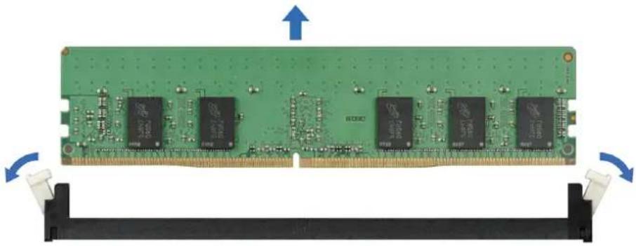
natural_image
Green RAM module with multiple black memory chips and a blue directional arrow indicating rotation (no text or symbols on the chip itself)Figure 68. Removing a memory module
Next steps
-
Install the memory module.
-
If you are removing the memory module permanently, install a memory module blank. The procedure to install a memory module blank is similar to that of the memory module.
Installing a memory module
The procedure for installing a DIMM module and an NVDIMM-N module is identical.
Prerequisites
Follow the safety guidelines listed in Safety instructions.

CAUTION: Ensure that you install the NVDIMM-N battery if you are using NVDIMM-N.

CAUTION: To prevent data loss and potential damage to your system, ensure that your system, LEDs on system, LEDs on NVDIMM-N and LEDs on NVDIMM-N battery are turned off before installing the NVDIMM-N battery.

CAUTION: To ensure proper system cooling, memory module blanks must be installed in any memory socket that is not occupied. Remove memory module blanks only if you intend to install memory modules in those sockets.
Steps
- Locate the appropriate memory module socket.

CAUTION: Handle each memory module only by the card edges, ensuring not to touch the middle of the memory module or metallic contacts.

CAUTION: To prevent damage to the memory module or the memory module socket during installation, do not bend or flex the memory module. You must insert both ends of the memory module simultaneously.
-
Open the ejectors on the memory module socket outward to allow the memory module to be inserted into the socket.
-
Align the edge connector of the memory module with the alignment key of the memory module socket, and insert the memory module in the socket.

CAUTION: Do not apply pressure at the center of the memory module; apply pressure at both ends of the memory module evenly.

NOTE: The memory module socket has an alignment key that enables you to install the memory module in the socket in only one orientation.
- Press the memory module with your thumbs until the socket levers firmly click into place.
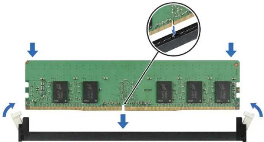
natural_image
Green RAM module with multiple 120M chips, showing internal wiring and mounting bracket (no text or symbols visible)Figure 69. Installing a memory module
For more information on the memory slot locations, see the System memory population topic.
Next steps
- Install the air shroud.
- Follow the procedure listed in After working inside your system.
- To verify if the memory module has been installed properly, press F2 and navigate to System Setup Main Menu > System BIOS > Memory Settings. In the Memory Settings screen, the System Memory Size must reflect the updated capacity of the installed memory.
- If the value is incorrect, one or more of the memory modules may not be installed properly. Ensure that the memory module is firmly seated in the memory module socket.
- Run the system memory test in system diagnostics.
Processors and heat sinks
Removing a processor and heat sink module
Prerequisites
WARNING: The heat sink may be hot to touch for some time after the system is powered down. Allow the heat sink to cool before removing it.
NOTE: For a processor greater than 150 W, you need to use high performance heat sink and processor module.
- Follow the safety guidelines listed in Safety instructions.
- Follow the procedure listed in Before working inside your system.
- Remove the air shroud.
Steps
- Using a Torx #T30 screwdriver, loosen the screws on the heat sink in the order below:
a) Loosen the first screw three turns.
b) Loosen the second screw completely.
c) Return to the first screw and loosen it completely.
-
Pushing both blue retention clips simultaneously, lift the processor and heat sink module (PHM).
-
Set the PHM aside with the processor side facing up.

natural_image
Two views of a heat sink cooling system with a close-up of its internal circuit board (no text or symbols visible)Figure 70. Removing the processor and heat sink module
Next steps
- Install the PHM.
Removing the processor from the processor and heat sink module
Prerequisites

NOTE: Only remove the processor from the processor and heat sink module if you are replacing the processor or heat sink. This procedure is not required when replacing a system board.
- Follow the safety guidelines listed in Safety instructions.
- Follow the procedure listed in Before working inside your system.
- Remove the air shroud.
- Remove the processor and heat sink module.
Steps
-
Place the heat sink with the processor side facing up.
-
Insert a flat blade screwdriver into the release slot marked with a yellow label. Twist (do not pry) the screwdriver to break the thermal paste seal.
-
Push the retaining clips on the processor bracket to unlock the bracket from the heat sink.

natural_image
Diagram of a computer processor with cooling fan and screwdriver, showing internal components and heat transfer arrows (no text or symbols)Figure 71. Loosening the processor bracket
-
Lift the bracket and the processor away from the heat sink, and place the processor connector side down on the processor tray.
-
Flex the outer edges of the bracket to release the bracket from the processor.

NOTE: Ensure that the processor and the bracket are placed in the tray after you remove the heat sink.

natural_image
Close-up of hands installing a black plastic component on a CPU socket (no text or symbols visible)Figure 72. Removing the processor bracket
Next steps
- Install the processor into the processor and heat sink module.
Installing the processor into a processor and heat sink module
Prerequisites
Follow the safety guidelines listed in Safety instructions.
Steps
- Place the processor in the processor tray.
NOTE: Ensure that the pin 1 indicator on the processor tray is aligned with the pin 1 indicator on the processor.
- Flex the outer edges of the bracket around the processor ensuring that the processor is locked into the clips on the bracket.
NOTE: Ensure that the pin 1 indicator on the bracket is aligned with the pin 1 indicator on the processor before placing the bracket on the processor.
NOTE: Ensure that the processor and the bracket are placed in the tray before you install the heat sink.
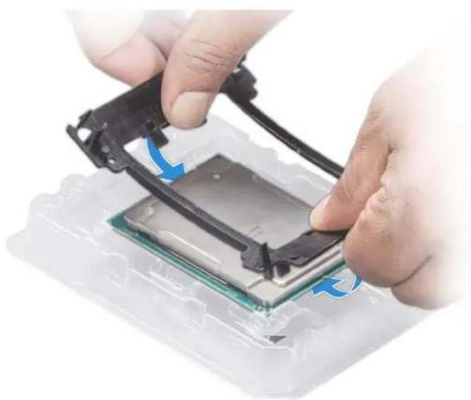
natural_image
Close-up of hands installing a CPU into a motherboard with blue arrows indicating the process (no text or symbols visible)Figure 73. Installing the processor bracket
- If you are using an existing heat sink, remove the thermal grease from the heat sink by using a clean lint-free cloth.
- Use the thermal grease syringe included with your processor kit to apply the grease in a quadrilateral design on the top of the processor.
CAUTION: Applying too much thermal grease can result in excess grease coming in contact with and contaminating the processor socket.
NOTE: The thermal grease syringe is intended for single use only. Dispose the syringe after you use it.

natural_image
Close-up of a medical device with a syringe inserted into a transparent plastic housing (no visible text or symbols)Figure 74. Applying thermal grease on top of the processor
- Place the heat sink on the processor and push down on the base of the heat sink until the bracket locks onto the heat sink.

NOTE:
- Ensure that the two guide pin holes on the bracket match the guide holes on the heat sink.
- Do not press on the heat sink fins.
- Ensure that the pin 1 indicator on the heat sink is aligned with the pin 1 indicator on the bracket before placing the heat sink onto the processor and bracket.

natural_image
Exploded view of a heat sink cooling system with cooling fins and heatsink (no text or symbols visible)Figure 75. Installing the heat sink onto the processor
Next steps
- Install the processor and heat sink module.
- Install the air shroud.
- Follow the procedure listed in After working inside your system.
Installing a processor and heat sink module
Prerequisites

CAUTION: Never remove the heat sink from a processor unless you intend to replace the processor. The heat sink is necessary to maintain proper thermal conditions.
- Follow the safety guidelines listed in Safety instructions.
- If installed, remove the processor blank and CPU dust cover.
Steps
- Align the pin 1 indicator of the heat sink to the system board and then place the processor and heat sink module (PHM) on the processor socket.

CAUTION: To avoid damaging the fins on the heat sink, do not press down on the heat sink fins.
NOTE: Ensure that the PHM is held parallel to the system board to prevent damaging the components.
- Push the blue retention clips inward to allow the heat sink to drop into place.
- Using the Torx #T30 screwdriver, tighten the screws on the heat sink in the order below:
a) Partially tighten the first screw (approximately 3 turns).
b) Tighten the second screw completely.
c) Return to the first screw and tighten it completely.
If the PHM slips off the blue retention clips when the screws are partially tightened, follow these steps to secure the PHM:
a. Loosen both the heat sink screws completely.
b. Lower the PHM on to the blue retention clips, following the procedure described in step 2.
c. Secure the PHM to the system board, following the replacement instructions listed in this step above. 4.
NOTE: The processor and heat sink module retention screws should not be tightened to more than 0.13 kgf-m (1.35 N.m or 12 in-lbf).
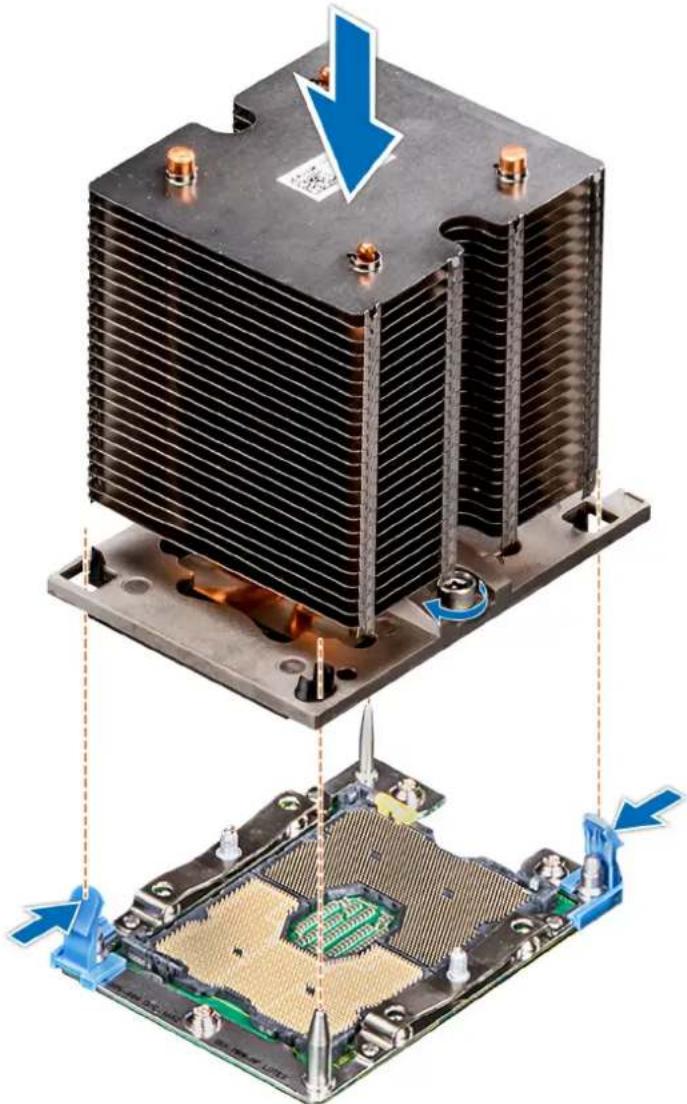
natural_image
Two views of a heat sink cooling system with a blue arrow indicating the cooling process (no text or symbols present)Figure 76. Installing a processor and heat sink module
Next steps
- Follow the procedure listed in After working inside your system.
Expansion card holder
Removing the expansion card holder
Prerequisites
- Follow the safety guidelines listed in Safety instructions.
- Follow the procedure listed in Before working inside your system.
Steps
- Press the tab and slide the expansion card holder up.
- Lift the expansion card holder away from the chassis.
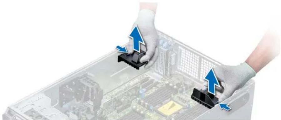
natural_image
Two hands in gloves installing blue arrows on a computer chassis with circuit board background (no text or symbols)Figure 77. Removing the expansion card holder
Next steps
- Install the expansion card holder.
Installing the expansion card holder
Prerequisites
Follow the safety guidelines listed in Safety instructions.
Steps
Align the expansion card holder with the guide pins on the system and push it down until it locks in place.
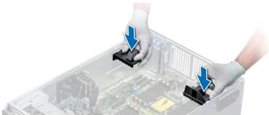
natural_image
Two hands in gloves installing a black plastic component into an open computer chassis (no text or symbols visible)Figure 78. Installing the expansion card holder
Next steps
- Follow the procedure listed in After working inside your system.
GPU card holder (optional)
GPU card restriction
The restrictions for GPU card is listed below:
- Requires cooling fan assembly (middle high-performance fans) and 1 or 2 external fans.
• If a GPU is installed in slot 1, 3, the right external fan is required. If a GPU is installed in slot 6, 8, both external fans are required. - Two external fans are required for GPU-ready SKUs, there is no SKU with left external fan only.
- If a GPU is installed on slot 1 or 3, only one 5.25 inch RMSD device (ODD/RD1000/half-height tape) is supported.
- Four single width GPUs cannot be supported if the second PERC with battery (H730/H730P/H830).
- 300 W GPUs only support the maximum ambient temperature of 30^ .
- GPU is not supported for 3.5 inch x 18 chassis and fresh air condition.
- GPU is only supported in rack mode.
- The left and right external fans are required when a GPU is installed in slots 6 and 8.
GPU card installation guidelines
Observe the following guidelines while installing a GPU card:
- GPU are supported only in the Rack mode configuration.
- GPU can be installed only on systems that have 1100 W or higher power supply units.
• Each GPU card supports up to 32 GB of dedicated GDDR5 memory.
- Two double-width GPU cards on a single processor configuration and four double width GPU cards on a dual processor configuration do not support any other add-on cards.
- The GPU cards must be installed:
- On GPU enabled system (two processor and also contains the main air shroud and GPU air shrouds).
- On systems with eight fan configuration (Fan1, Fan2 are standard (STD) fans. Fan3-Fan6 are high-performance (HPR) fans. Fan7 and Fan8 are external Left and Right fans).
- Specific GPU cards will need the use of the dongle power cable.
Removing the optional GPU card holder
Prerequisites
- Follow the safety guidelines listed in Safety instructions.
- Follow the procedure listed in Before working inside your system.
- Remove the air shroud.
Steps
Press the release tab and slide the graphical processing unit (GPU) card holder out of the chassis.

natural_image
3D rendering of a server chassis with an attached mechanical component, showing internal components and a magnified inset (no text or symbols visible)Figure 79. Removing the GPU card holder
Next steps
- Install the optional GPU card holder.
Installing the optional GPU card holder
Prerequisites
Follow the safety guidelines listed in Safety instructions.
Steps
Align the GPU card holder with the slots and the guide pin on the system, and push the GPU card holder down until it locks in place.
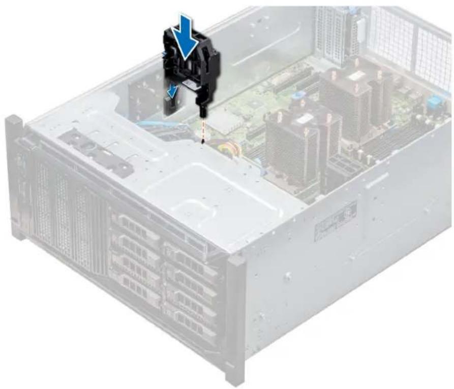
natural_image
Interior view of a server rack with highlighted internal components and a blue downward arrow indicating a specific component (no text or symbols present)Figure 80. Installing the optional GPU card holder
Next steps
- Install the air shroud.
- Follow the procedure listed in After working inside your system.
Expansion cards
Expansion card installation guidelines
The following table describes the supported expansion cards:
Table 40. Supported PCI express generation 3 expansion cards
PCIe Slot Processor Connection Height Length Link Width Slot Width
| 0 (Gen3) | Processor 1 - Half Length x8 x8 |
| (dedicated for PERC or HBA) | |
| 1 (Gen3) | Processor 1 Standard Height Full Length x16 x16 |
| 2 (Gen3) | Processor 1 Standard Height Full Length x4 x8 |
| 3 (Gen3) | Processor 1 Standard Height Full Length x16 x16 |
| 4 (Gen3) | Processor 2 Standard Height Half Length x8 x8 |
| 5 (Gen3) | Processor 2 Standard Height Full Length x4 x8 |
| 6 (Gen3) | Processor 2 Standard Height Full Length x16 x16 |
| 7 (Gen3) | Processor 2 Standard Height Full Length x8 x8 |
| 8 (Gen3) | Processor 2 Standard Height Full Length x16 x16 |

NOTE: To use PCIe slots 4-8, both the processors must be installed.
Expansion card slot priority
The following table describes the installation order for installing expansion cards to ensure proper cooling and mechanical fit. The expansion cards with the highest priority must be installed first by using the slot priority indicated.
NOTE: To use PCIe slots 4, 5, 6, 7, and 8, both the processors must be installed.
NOTE: The expansion card slots are not hot-swappable.
NOTE: To use PCIe cards with external I/O in slots 1, 2, 3, right external fan must not be installed, and to use PCIe cards with external I/O in slots 5, 6, 7, 8, left external fan must not be installed.
Table 41. Expansion card installation order
| System Configuration Card | Priority | Card Type Slot Priority Maximum | Allowed | ||
| 1 or 2 CPU, no GPU (no external fan) | 1 Dell PowerEdge Express Flash (PCIe SSD) Bridge 1, 3 2 | ||||
| 2 RAID (H330), RAID (H730P) 0 1 | |||||
| RAID (H740P) 0, 1 2 | |||||
| RAID (H840), BOSS 4, 7, 1, 6, 8 5 | |||||
| 3 Intel OPA NIC 1, 6 3 | |||||
| Mellanox CX4 DP 100 Gb NICs* 8, 1, 6, 3 4 | |||||
| Mellanox CX4 SP 100 Gb NIC* | 8 1 | ||||
| 4 Intel 40 Gb NIC | 4, 7, 1, 6, 8, 3 | 6 | |||
| Mellanox DP 40 Gb NIC* | 8, 4, 7, 1, 6 5 | ||||
| Mellanox SP 25 Gb NIC | 4, 7, 1, 6, 8 5 | ||||
| Intel DP 25 Gb NIC, Qlogic DP 25 Gb NIC | 4, 7, 1, 6 | 4 | |||
| Broadcom DP 25 Gb NIC | 4, 7, 1, 6, 8, 3 | 6 | |||
| 5 | FC32 HBAs, FC16 HBAs | 4, 7, 1, 6, 8 5 | |||
| 6 | Intel QP 10 Gb Base-T NIC* | 8 1 | |||
| 7 Intel DP 10 Gb Base-T NIC, Intel 4x 10 Gb SFP+ NIC,Broadcom DP 10 Gb 57416 NIC, Qlogic DP 10 GbSFP V2 NIC, Mellanox DP 10 Gb SFP+ NIC | 4, 7, 1, 6, 8 5 | ||||
| Intel DP 10 Gb SFP+ NICs, Broadcom DP 10 Gb57412 NIC, Qlogic QLGX 10 Gb NICs | 4, 7, 1, 6, 8, 3 | 6 | |||
| Solarflare DP 10 Gb NICs*, Qlogic DP 10 Gb V1 NIC* | 8, 4, 1, 7, 6 5 | ||||
| Qlogic DP 10 Gb SFP V1 NIC, Qlogic DP 10 Gb V2NIC | 4, 7, 1, 6 | 4 | |||
| 8 | FC8 HBAs | 4, 7, 1, 6, 8, 5, 3, 2 | 8 | ||
| 9 | 12G SAS HBA | 4, 7, 1, 6, 8, 3 | 6 | ||
| HBA330 | 0, 1, 3 | 2 | |||
| 10 | PCIe SSD | 8, 4, 7, 1, 6 5 | |||
| 2 CPU, 1 External fan (Right) | 1 GPUs | 3, 1 2 | |||
| RAID (H330), RAID (H730) | 0 1 | ||||
| RAID (H740) | 0, 1, 3 | 2 | |||
| System Configuration Card | Priority | Card Type Slot Priority Maximum | Allowed | |||
| RAID (H840) 7, 8, 6, 4 4 | ||||||
| BOSS 1, 3, 7, 8, 6, 4 6 | ||||||
| 2 100 Gb NICs 8, 6 4 | ||||||
| 3 40 Gb NICs, 25 Gb NICs 7, 8, 6, 4 4 | ||||||
| 4 FC32 HBAs, FC16 HBAs 7, 8, 6, 4 4 | ||||||
| 5 10 Gb NICs 7, 8, 6, 4 4 | ||||||
| 6 FC8 HBAs 7, 8, 6, 4 4 | ||||||
| 7 1 Gb NICs | 7, 8, 6, 4 4 | |||||
| 8 12Gb SAS HBA | 7, 8, 6, 4 4 | |||||
| 9 HBA330 | 0, 1, 3 | 2 | ||||
| 10 | PCIe SSD | 1, 3, 7, 8, 6, 4 6 | ||||
| 2 CPU, 2 External fans | 1 | Dell PowerEdge Express Flash (PCIe SSD) Bridge | 1, 3 | 2 | ||
| 2 GPUs | 3, 6, 8, 1 4 | |||||
| RAID (H330), RAID (H730) | 0 | 1 | ||||
| RAID (H740) | 0, 1,3 | 2 | ||||
| RAID (H840) 4 | 1 | |||||
| BOSS 1, 3, 7, 8, 6, 4 6 | ||||||
| 3 NICs | 4 | 1 | ||||
| 4 12Gb SAS HBA | 4 | 1 | ||||
| HBA330 | 0, 1, 3 | 2 | ||||
| 5 PCIe SSD | 1, 3, 7, 8, 6, 4 6 | |||||
NOTE: The PCIe cards with × require the cooling fan assembly (middle fans) to support.
NOTE: Without external fans, Mellanox CX4 SP 100 Gb NIC and Intel QP 10 Gb Base-T NIC are only allowed on slot 8 and 2 CPU configuration.
Removing a expansion card
Prerequisites
- Follow the safety guidelines listed in Safety instructions.
- Follow the procedure listed in Before working inside your system.
- Remove the air shroud.
- Remove the expansion card holder.
Steps
- If installed, disconnect the data cables from the PERC card and/or the power cables from the GPU card.
- Press the expansion card latch and push down the latch to open it.
- Hold the expansion card by its edge, and pull the card up to remove it from the expansion card connector and the system.
- Install the filler brackets by performing the following steps:
a) Align the slot on the filler bracket with the tab on the expansion card slot.
b) Press the expansion card latch till the filler bracket locks into place.
NOTE: Filler brackets must be installed in empty expansion-card slots to maintain FCC certification of the system. The brackets also keep dust and dirt out of the system and aid in proper cooling and airflow inside the system.
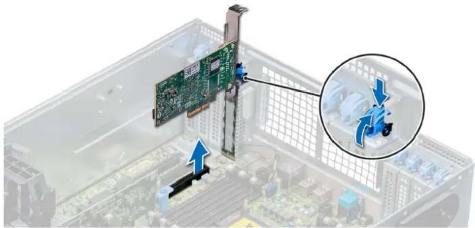
natural_image
Close-up of a computer motherboard showing a green card with connectors and a magnified inset highlighting a mechanical component (no text or symbols visible)Figure 81. Removing an expansion card
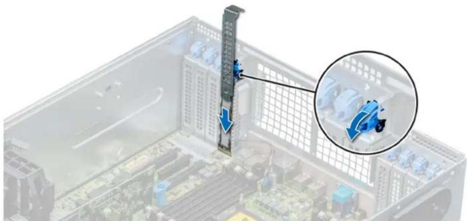
natural_image
3D view of a computer tower with a vertical monitor and a magnified inset showing a blue mechanical component (no text or symbols visible)Figure 82. Installing the filler bracket
Next steps
- Install an expansion card.
Installing an expansion card
Prerequisites
- Follow the safety guidelines listed in Safety instructions.
- Remove the air shroud.
- Remove the expansion card holder.
Steps
- Unpack the expansion card and prepare it for installation.
For instructions, see the documentation accompanying the card. - Open the expansion card latch adjacent to the slot you want to install the expansion card.
- Remove the existing expansion card or filler bracket from the expansion card holder.

NOTE: Store this bracket for future use. Filler brackets must be installed in empty expansion-card slots to maintain FCC certification of the system. The brackets also keep dust and dirt out of the system and aid in proper cooling and airflow inside the system.
-
Holding the card by its edges, position the card so that the card aligns with the expansion card connector.
-
Insert the card firmly into the expansion card connector until the card is fully seated.
- Close the expansion card latch by pushing the latch up until the latch snaps into place.
- Connect the data cables to the expansion card and/or the power cables to the GPU card.
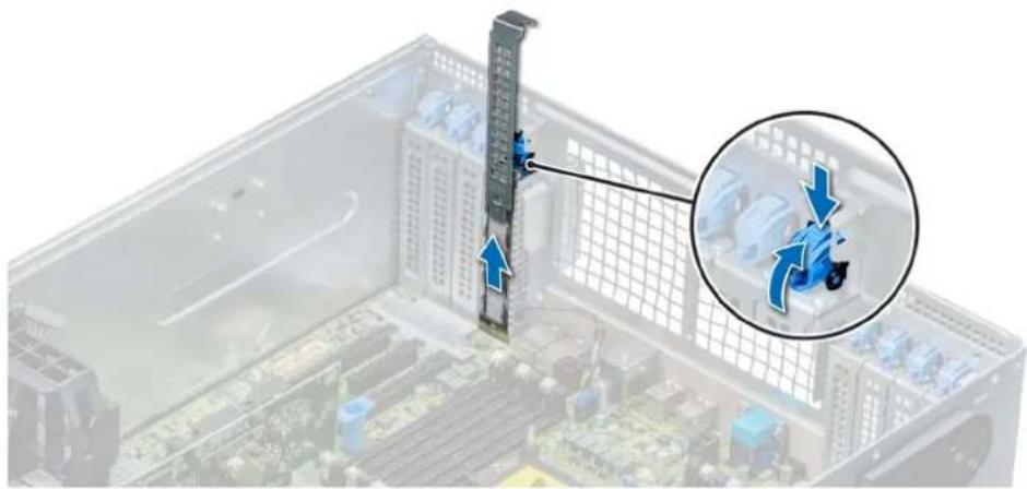
natural_image
Interior view of a computer motherboard with a vertical monitor and a magnified inset showing a blue mechanical component (no text or symbols visible)Figure 83. Removing the filler bracket

natural_image
3D diagram of a computer tower with a green circuit board and blue connectors, showing a magnified inset of a blue mechanical component (no text or symbols present)Figure 84. Installing an expansion card
Next steps
- Install the expansion card holder.
- Follow the procedure listed in After working inside your system.
M.2 SSD module
Removing the M.2 SSD module
Prerequisites
- Follow the safety guidelines listed in Safety instructions.
- Follow the procedure listed in Before working inside your system.
- Remove the air shroud.
- Remove the BOSS card.

NOTE: Removing the BOSS card is similar to the procedure for removing an expansion card riser.
Steps
- Loosen the screws and lift the retention straps that secure the M.2 SSD module on the BOSS card.
- Pull the M.2 SSD module away from the BOSS card.
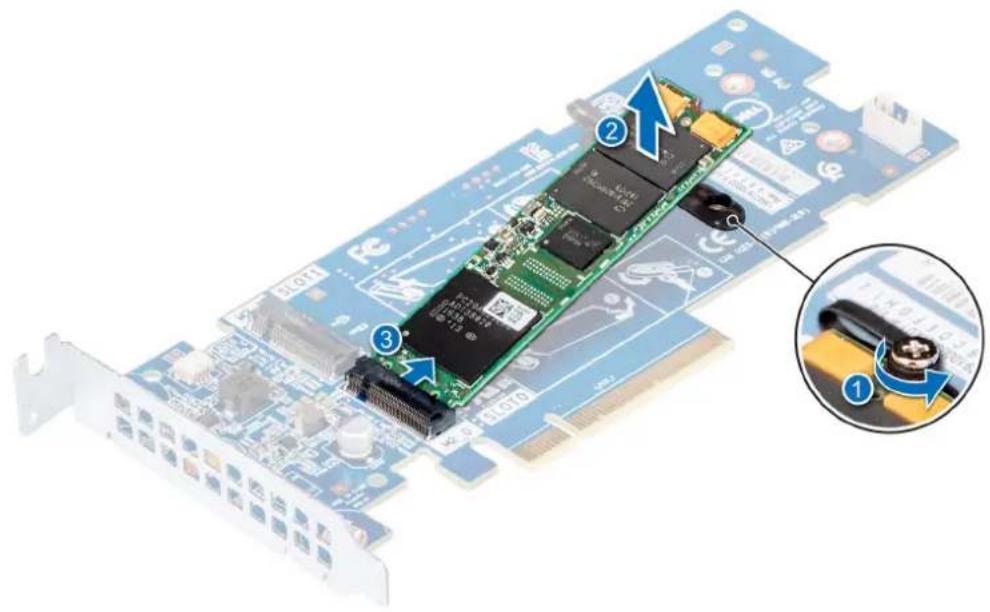
text_image
Diagram of a PCI EDS card with labeled components and an inset close-up showing the internal structure.Figure 85. Removing the M.2 SSD module
Next steps
- Install the M.2 SSD module.
Installing the M.2 SSD module
Prerequisites
- Follow the safety guidelines listed in Safety instructions.
Steps
- Align the M.2 SSD module connectors with the connectors on the BOSS card.
- Push the M.2 SSD module until the module is seated firmly on the BOSS card.
- Secure the M.2 SSD module on the BOSS card with the retention straps and screws.

text_image
Diagram of a PCI EDS card with labeled components and a magnified inset showing the internal mechanism.Figure 86. Installing the M.2 SSD module
Next steps
- Install the BOSS card.
NOTE: Installing the BOSS card is similar to installing the expansion card riser.
- Install the air shroud.
- Follow the procedure listed in After working inside your system.
Optional MicroSD or vFlash card
Removing the MicroSD card
Prerequisites
- Follow the safety guidelines listed in Safety instructions.
- Follow the procedure listed in Before working inside your system.
Steps
- Locate the MicroSD card slot on the vFlash/IDSDM module, and press the card to partially release it from the slot. To locate IDSDM/vFlash module, see the System board jumpers and connectors section.
- Hold the MicroSD card and remove it from the slot.
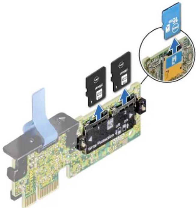
text_image
Write Protection 16 2 3 4 5 6 7 8 9 10 11 12 13 14 15 16 17 18 19 20 21 22 23 24 25 26 27 28 29 30 31 32 33 34 35 36 37 38 39 40 41 42 43 44 45 46 47 48 49 50 51 52 53 54 55 56 57 58 59 60 61 62 63 64 65 66 67 68 69 70 71 72 73 74 75 76 77 78 79 80Figure 87. Removing the MicroSD card from the slot
NOTE: Temporarily label each MicroSD card with its corresponding slot number after removal.
Next steps
- Install a MicroSD card.
Installing the MicroSD card
Prerequisites
Follow the safety guidelines listed in Safety instructions.
NOTE: To use an MicroSD card with your system, ensure that the Internal SD Card Port is enabled in System Setup.
NOTE: If reinstalling, ensure that you install the MicroSD cards into the same slots based on the labels you had marked on the cards during removal.
Steps
- Locate the MicroSD card connector on the IDSDM/vFlash module. Orient the MicroSD card appropriately and insert the contact-pin end of the card into the slot. To locate IDSDM/vFlash, see the System board jumpers and connectors section.
NOTE: The slot is keyed to ensure correct insertion of the card.
- Press the card into the card slot to lock it into place.

text_image
46 Write Protection off 46Figure 88. Installing the MicroSD card
Next steps
- Follow the procedure listed in After working inside your system.
Optional IDSDM or vFlash module
Removing the optional IDSDM or vFlash module
Prerequisites
- Follow the safety guidelines listed in Safety instructions.
- Follow the procedure listed in Before working inside your system.
- If you are replacing the IDSDM/vFlash module, remove the MicroSD cards.
NOTE: Temporarily label each MicroSD card with its corresponding slot number after removal.
Steps
- Locate the IDSDM/vFlash connector on the system board.
To locate IDSDM/vFlash connector, see the System board jumpers and connectors section.
- Holding the pull tab, lift the IDSDM/vFlash module out of the system.

natural_image
Close-up of a green circuit board with an attached black connector and a blue upward arrow indicating motion (no text or symbols on the board itself)Figure 89. Removing the optional IDSDM/vFlash module

NOTE: There are two dip switches on the IDSDM/vFlash module for write-protection.
Next steps
- Install the optional IDSDM/vFlash card.
Installing optional IDSDM or vFlash module
Prerequisites
Follow the safety guidelines listed in Safety instructions.
Steps
- Locate the IDSDM/vFlash connector on the system board.
To locate IDSDM/vFlash connector, see the System board jumpers and connectors section. - Align the IDSDM/vFlash card with the connector on the system board.
- Push the IDSDM/vFlash module until it is firmly seated on the system board.

natural_image
Close-up of a green printed circuit board with blue arrows indicating a component or assembly process (no readable text or symbols)Figure 90. Installing optional IDSDM/vFlash module
Next steps
- Install the MicroSD cards.

NOTE: Reinstall the MicroSD cards into the same slots based on the labels you had marked on the cards during removal.
- Follow the procedure listed in After working inside your system.
Backplane
Backplane connectors
Depending on the configuration, your system supports one of the following:
- 8 x 3.5 inch SAS/SATA backplane
- 18 x 3.5 inch SAS/SATA backplane
- 8 x 2.5 inch Dell PowerEdge Express Flash (NVMe) backplane
-
16 x 2.5 inch SAS/SATA backplane with the optional additional backplanes below:
-
8 x 2.5 inch NVMe backplane
- 16 x 2.5 inch SAS/SATA backplane (FlexBay)
- 32 x 2.5 inch SAS/SATA backplane

text_image
Labeled diagram of a computer motherboard with numbered components for identificationFigure 91. 16 x 2.5 SAS/SATA backplane
- backplane power connector A [J_BP_PWR_A] 2. backplane power connector B [J_BP_PWR_B]
- optical drive power connector [J_ODD_PWR] 4. backplane signal connector [J_BP_SIG]
- SAS A0 connector [J_SAS_A0] 6. SAS B0 connector [J_SAS_B0]
- I2C connector

text_image
Labeled diagram of an electronic circuit board with numbered componentsFigure 92. 8 x 2.5 NVMe backplane
- backplane power connector [J_BP_PWR1] 2. PCIe B0 connector [J_PCIE_B0]
- PCIe A0 connector [J_PCIE_A0] 4. backplane signal connector [J_BP_SIG1]
- PCIe A1 connector [J_PCIE_A1] 6. PCIe B1 connector [J_PCIE_B1]
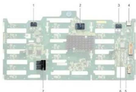
text_image
Labeled diagram of an electronic circuit board with numbered componentsFigure 93. 18 x 3.5 SAS/SATA backplane
- backplane power connector A [J_BP_PWR_A1] 2. controller
- backplane power connector B [J_BP_PWR_B1] 4. optical drive power connector [J_ODD1]
- I2C connector 6. backplane signal connector [J_BP_SIG1]
- SAS A0_B0 connector [J_SAS_A0_B0]

text_image
1 2 3 4 5Figure 94. 8 x 3.5 SAS/SATA backplane
- optical drive power connector [J_ODD1] 2. backplane power connector [J_BP_PWR_A]
- SAS A0 connector [J_BP_SIG] 4. backplane signal connector [J_SAS_A0]
- SAS B0 connector [J_SAS_B0]
Removing a backplane
Prerequisites

CAUTION: To prevent damage to the drives and backplane, you must remove the hard drives from the system before removing the backplane.

CAUTION: You must note the number of each hard drive and temporarily label them before removal so that you can replace them in the same locations.
- Follow the safety guidelines listed in Safety instructions.
- Follow the procedure listed in Before working inside your system.
- Remove all the drives.
- If installed, remove the middle cooling fan assembly.
Steps
- Disconnect the data, signal, and power cables from the backplane.
- Pull the release pin and holding the pin, lift the backplane out of the system.
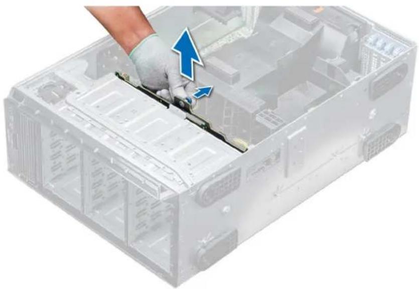
natural_image
Close-up of a server rack with a hand holding a cable, showing internal components and a blue arrow indicating direction (no text or symbols)Figure 95. Removing a backplane
Next steps
- Install a backplane.
Installing a backplane
Prerequisites
- Follow the safety guidelines listed in Safety instructions.
- Follow the procedure listed in Before working inside your system.
Steps
- Use the hooks at the base of the system as guides to align the hard drive backplane.
- Lower the hard-drive backplane into the system till the release pin locks in place, securing the hard drive backplane to the system.
- Connect the data, signal, and power cables to the backplane.
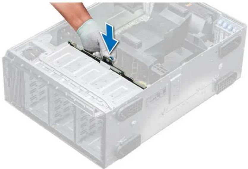
natural_image
Close-up of a server rack with a hand holding a cable, showing internal components and a blue arrow indicating a downward motion (no text or symbols)Figure 96. Installing a backplane
Next steps
- If removed, install the middle cooling fan assembly.
- Install the drives into their original slots.
- Follow the procedure listed in After working inside your system.
Backplane cabling

text_image
1 2 3 4 5 6 7 8Figure 97. 2.5 inch x32 SAS/SATA to internal PERC and PERC adapter
- 2.5 inch x 16 backplane (flex bay) 2. SAS cable (BP: J_EXP_A1 to PERC adapter)
- SAS cable (BP: J_EXP_B1 to PERC adapter) 4. internal PERC card
- PERC adapter 6. SAS cable (BP: J_SAS_A0 to internal PERC card)
- SAS cable (BP: J_SAS_B0 to internal PERC card) 8. 2.5 inch x 16 backplane

text_image
1 2 3 4 5 6 7 8 11 10 9Figure 98. 2.5 inch x16 SAS/SATA to internal PERC with 2.5 inch x8 NVMe to PCIe bridge
- 2.5 inch x8 NVMe backplane 2. NVMe cable (BP: J_PCIE_B0 to PCIe bridge: J6)
- NVMe cable (BP: J_PCIE_A0 to PCIe bridge: J5) 4. NVMe cable (BP: J_PCIE_B1 to PCIe bridge: J6)
- NVMe cable (BP: J_PCIE_A1 to PCIe bridge: J5) 6. internal PERC card
- PCIe bridge on Slot 18. PCIe bridge on Slot 3
- SAS cable (BP: SAS_B0 to internal PERC card: SAS_B) 10. SAS cable (BP: SAS_A0 to internal PERC card: SAS_A)
- 2.5 inch x16 SAS/SATA backplane

text_image
Diagram of a device interior with labeled components and colored wiring, showing internal structure and connections.Figure 99. 3.5 inch x8 SAS/SATA to internal PERC
1. SAS cable (BP: SAS_A0 to internal PERC card: SAS_A) 2. SAS cable (BP: SAS_B0 to internal PERC card: SAS_B)

text_image
Technical diagram of a device interior with labeled components and colored wiring pathsFigure 100. 3.5 inch x8 onboard SAS controller
- SAS cable (BP: SAS_A0 to MB: SAS_A)
- SAS cable (BP: SAS_B0 to MB: SAS_B)
- 3.5 inch x8 SAS/SATA backplane
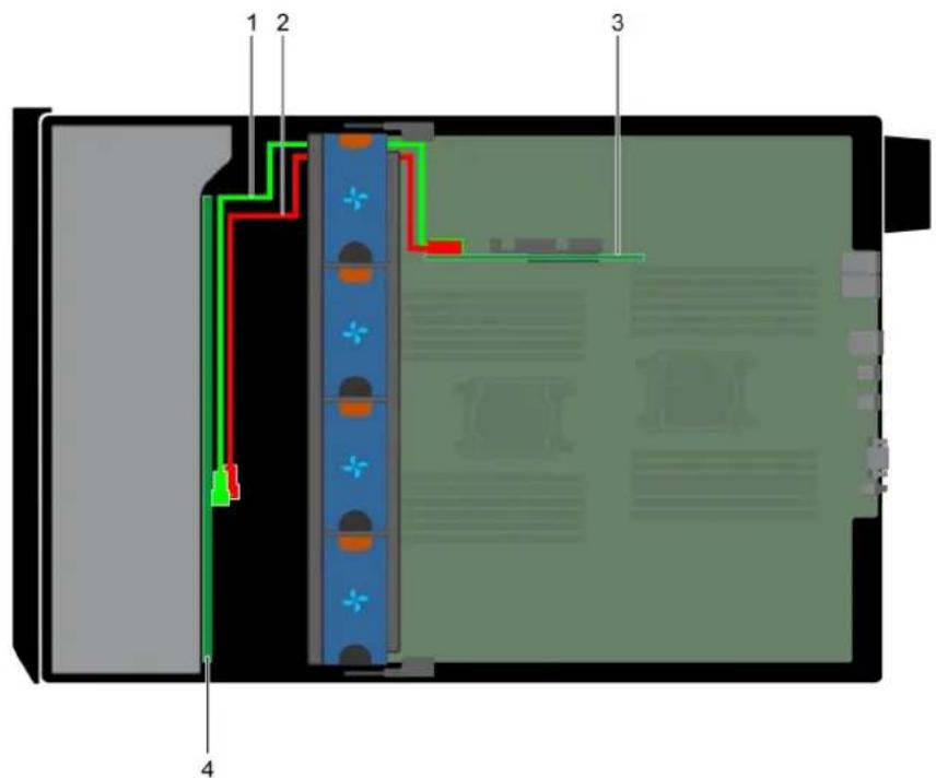
text_image
1 2 3 4Figure 101. 3.5 inch x18 internal PERC
- SAS cable (BP: SAS_A0 to internal PERC card: SAS_A) 2. SAS cable (BP: SAS_B0 to internal PERC card: SAS_B)
- internal PERC card 4. 3.5 inch x18 SAS/SATA backplane
Integrated storage controller card
Removing the integrated storage controller card
Prerequisites
- Follow the safety guidelines listed in Safety instructions.
- Follow the procedure listed in Before working inside your system.
- Remove the air shroud.
- Remove the GPU card holder.
Steps
- Holding the integrated storage controller card firmly, lift the card out of the server.
- Disconnect the data cables from the integrated storage controller.

natural_image
Person in gloves installing a circuit board with an inset image of a server room (no text or symbols visible)Figure 102. Removing the integrated storage controller card
Next steps
- Install the integrated storage controller card.
Installing the integrated storage controller card
Prerequisites
Follow the safety guidelines listed in Safety instructions.
Steps
- Connect the data cables from the integrated storage controller.
- Holding the storage controller card firmly, insert the card into the dedicated slot on the system board.

natural_image
Person in gloves installing a circuit board with a monitor, placed on an open computer motherboard (no visible text or symbols)Figure 103. Installing the integrated storage controller card
Next steps
- Install the GPU card holder.
- Install the air shroud.
- Follow the procedure listed in After working inside your system.
System battery
Replacing the system battery
Prerequisites

WARNING: There is a danger of a new battery exploding if it is incorrectly installed. Replace the battery only with the same or equivalent type recommended by the manufacturer. For more information, see the safety information that shipped with your system.
- Follow the safety guidelines listed in Safety instructions.
- Follow the procedure listed in Before working inside your system.
- If installed, disconnect the power or data cables from expansion card(s).
Steps
- Locate the battery socket. For more information, see the System board jumpers and connectors section.

CAUTION: To avoid damage to the battery connector, you must firmly support the connector while installing or removing a battery.
- Use a plastic scribe to pry out the system battery.
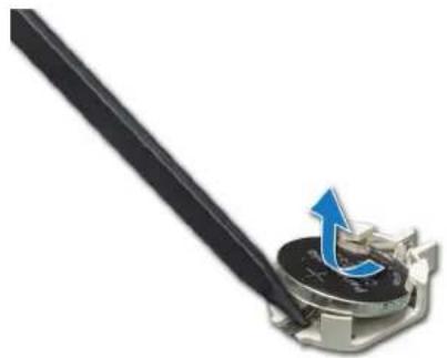
natural_image
Close-up of a mechanical component with a blue arrow indicating rotation or movement (no text or symbols visible)Figure 104. Removing the system battery
- To install a new system battery, hold the battery with the positive side facing up and slide it under the securing tabs.
- Press the battery into the connector until it snaps into place.

Figure 105. Installing the system battery
Next steps
- If removed, connect the cables to the expansion card(s).
- Follow the procedure listed in After working inside your system.
- While booting, press F2 to enter the System Setup and ensure that the battery is operating properly.
- Enter the correct time and date in the System Setup Time and Date fields.
- Exit the System Setup.
Optional internal USB memory key
Replacing the optional internal USB memory key
Prerequisites

CAUTION: To avoid interference with other components in the server, the maximum permissible dimensions of the USB memory key are 15.9 mm wide x 57.15 mm long x 7.9 mm high.
-
Follow the safety guidelines listed in Safety instructions.
-
Follow the procedure listed in Before working inside your system.
Steps
- Locate the USB port or USB memory key on the system board.
To locate the USB port, see the System board jumpers and connectors. - If installed, remove the USB memory key from the USB port.
- Insert the replacement USB memory key into the USB port.
Next steps
- Follow the procedure listed in Before working inside your system.
- While booting, press F2 to enter System Setup and verify that the system detects the USB memory key.
Control panel assembly
Removing the control panel assembly
Prerequisites
- Follow the safety guidelines listed in Safety instructions.
- Follow the procedure listed in Before working inside your system.
- Remove the cooling fan assembly.
Steps
- Using the Phillips #2 screwdriver, remove the screw that secures control panel to the chassis.
- Disconnect the control panel cable and the control panel USB cable from the system board.

CAUTION: Do not use excessive force when removing the control panel cables as it can damage the connectors.
- Slide the control panel out of the chassis.

NOTE: Follow the same steps to remove the control panel in the rack-mode configuration.

natural_image
Exterior view of a server rack with multiple drive bays and ventilation fans, showing internal structure and a blue arrow indicating direction (no text or symbols)Figure 106. Removing the control panel assembly
- To remove the information tag, perform the following steps:
a) Locate and press the tabs on the information tag.
b) Push the information tag out of the slot to remove it from the control panel.

NOTE: Retain the information tag to replace it in the new control panel.
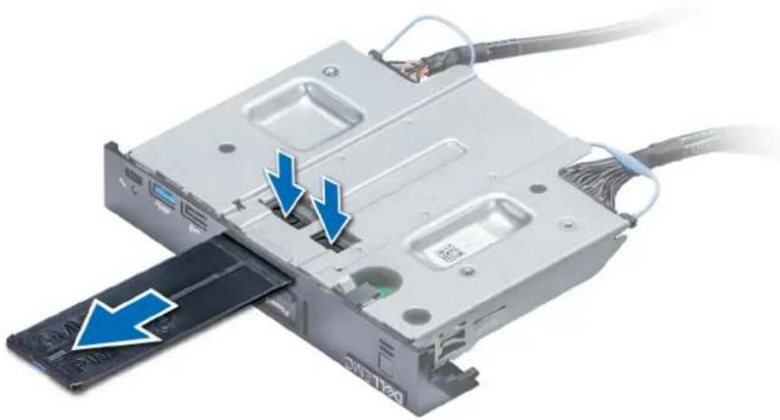
natural_image
Close-up of a computer internal component with blue arrows indicating ports or connections (no text or symbols visible)Figure 107. Removing the information tag
Next steps
- Install the control panel assembly.
Installing the control panel assembly
Prerequisites
Follow the safety guidelines listed in Safety instructions.
Steps
- Replace the blank information tag in the new control panel with the information tag retained from the old control panel.

natural_image
Close-up of a computer internal component with cable and drive slots, showing no visible text or symbols on the device itself.Figure 108. Installing the information tag
- To install the information tag, push the information tag into the control-panel slot.
- Connect the control panel cable and the control panel USB cable to the control panel assembly.
- Align and insert the control panel into the control panel slot in the chassis.
- Secure the control panel to the chassis by using the screw.
- Connect the control panel cable and the control panel USB cable to the system board.

natural_image
Exterior view of a server rack with multiple drive bays and ventilation fans, showing internal structure and a blue arrow pointing to a component (no text or symbols visible)Figure 109. Installing the control panel assembly
Next steps
- Install the cooling fan assembly.
- Follow the procedure listed in After working inside your system.
Trusted Platform Module
Upgrading the Trusted Platform Module
Prerequisites
- Follow the safety guidelines listed in Safety instructions.
- Follow the procedure listed in Before working inside your system.
NOTE:
- Ensure that your operating system supports the version of the TPM module being installed.
- Ensure that you download and install the latest BIOS firmware on your system.
- Ensure that the BIOS is configured to enable UEFI boot mode.
About this task

CAUTION: If you are using the Trusted Platform Module (TPM) with an encryption key, you may be prompted to create a recovery key during program or System Setup. Work with the customer to create and safely store this recovery key. When replacing this system board, you must supply the recovery key when you restart your system or program before you can access the encrypted data on your hard drives.

CAUTION: Once the TPM plug-in module is installed, it is cryptographically bound to that specific system board. Any attempt to remove an installed TPM plug-in module breaks the cryptographic binding, the removed TPM cannot be reinstalled or installed on another system board.
Removing the TPM
Steps
- Locate the TPM connector on the system board.
- Press to hold the module down and remove the screw using the security Torx 8-bit shipped with the TPM module.
- Slide the TPM module out from its connector.
- Push the plastic rivet away from the TPM connector and rotate it 90° counterclockwise to release it from the system board.
- Pull the plastic rivet out of its slot on the system board.
Installing the TPM
Steps
- To install the TPM, align the edge connectors on the TPM with the slot on the TPM connector.
- Insert the TPM into the TPM connector such that the plastic rivet aligns with the slot on the system board.
- Press the plastic rivet until the rivet snaps into place.

natural_image
Close-up of a green printed circuit board with a blue arrow indicating a mechanical component (no text or symbols visible)Figure 110. Installing the TPM
Next steps
- Install the system board.
- Follow the procedure listed in After working inside your system.
Initializing TPM for BitLocker users
Steps
Initialize the TPM.
For more information, see .
The TPM Status changes to Enabled, Activated.
Initializing the TPM 1.2 for TXT users
Steps
- While booting your system, press F2 to enter System Setup.
- On the System Setup Main Menu screen, click System BIOS > System Security Settings.
- From the TPM Security option, select On with Pre-boot Measurements.
- From the TPM Command option, select Activate.
- Save the settings.
- Restart your system.
- Enter System Setup again.
- On the System Setup Main Menu screen, click System BIOS > System Security Settings.
- From the Intel TXT option, select On.
System board
Removing the system board
Prerequisites

CAUTION: If you are using the Trusted Platform Module (TPM) with an encryption key, you may be prompted to create a recovery key during program or System Setup. Be sure to create and safely store this recovery key. If you replace this system board, you must supply the recovery key when you restart your system or program before you can access the encrypted data on your hard drives.

CAUTION: Do not attempt to remove the TPM plug-in module from the system board. Once the TPM plug-in module is installed, it is cryptographically bound to that specific system board. Any attempt to remove an installed TPM plug-in module breaks the cryptographic binding, and it cannot be reinstalled or installed on another system board.
- Follow the safety guidelines listed in Safety instructions.
- Follow the procedure listed in Before working inside your system.
- Remove the following:
a. Air shroud
b. GPU card holder, if installed
c. Expansion card holder
d. Cooling fan assembly, if installed
e. Expansion cards, if installed
f. Integrated storage controller card
g. vFlash/IDSDM module
h. Internal USB key, if installed
i. Processors and heat sink modules

CAUTION: To prevent damage to the processor pins when replacing a faulty system board, ensure that you cover the processor socket with the processor protective cap.
j. Memory modules
Steps
- Disconnect all cables from the system board.

CAUTION: Take care not to damage the system identification button while removing the system board from the chassis.

CAUTION: Do not lift the system board by holding a memory module, processor, or other components.
- Holding the post, lift the blue release pin, and slide the system board toward the front of the system. Sliding the system board toward the front of the chassis to disengage the connectors from the slots on the chassis.
- Holding the post, incline the system board at an angle, and lift the system board out of the chassis.
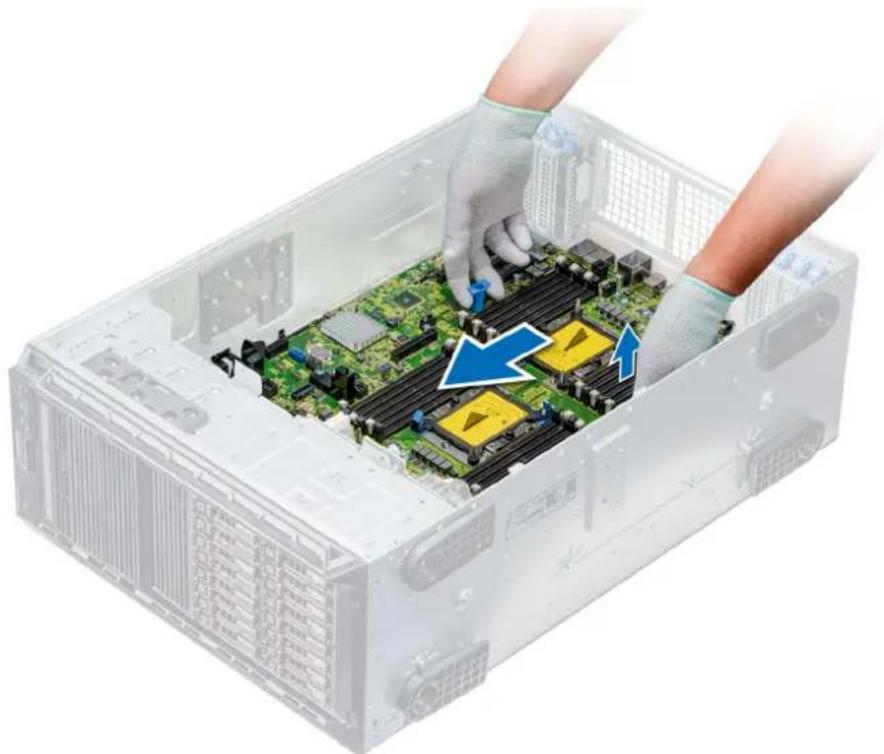
natural_image
Interior view of a server rack with hands installing or adjusting a CPU socket into the case (no text or symbols visible)Figure 111. Disengaging the system board
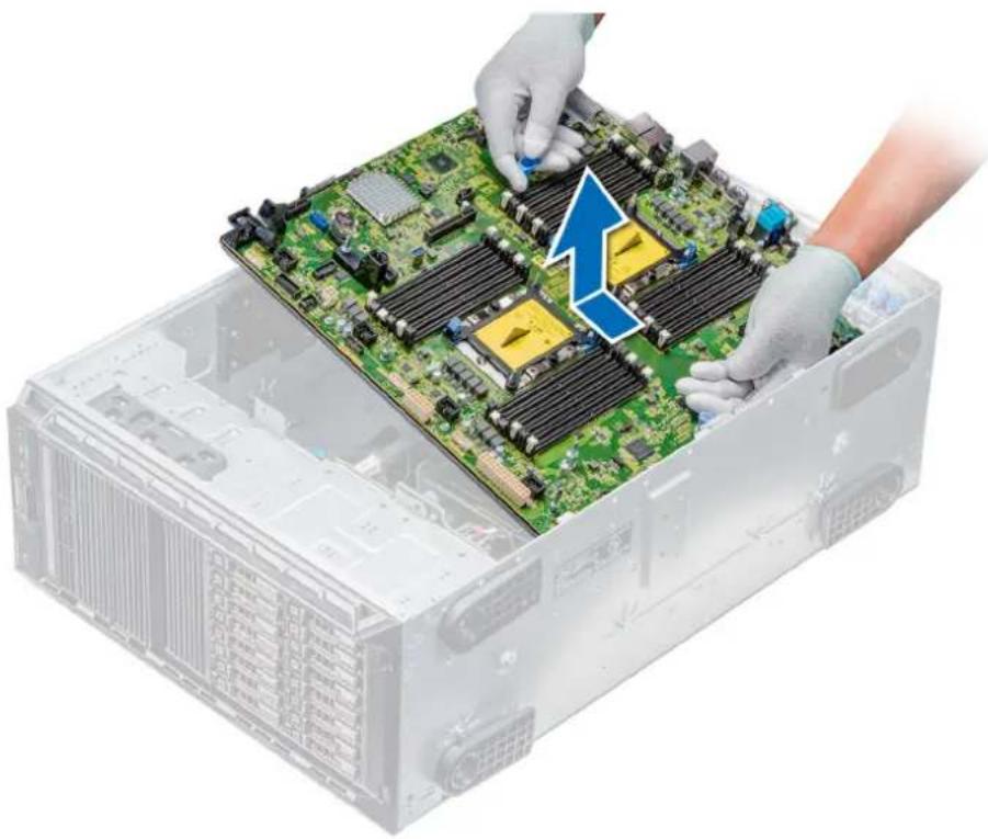
natural_image
Close-up of hands installing a green computer motherboard with a blue arrow highlighting the component (no text or symbols visible)Figure 112. Removing the system board
Next steps
- Install the system board.
Installing the system board
Prerequisites
Follow the safety guidelines listed in Safety instructions.
Steps
- Unpack the new system board assembly.

CAUTION: Do not lift the system board by holding a memory module, processor, or other components.

CAUTION: Take care not to damage the system identification button while placing the system board into the chassis.
- Holding the post, incline the system board, and lower the system board into the chassis.
- Holding the system board holder, push the system board toward the back of the system until the release pin clicks into place.

natural_image
Person in gloves installing a green computer motherboard inside a transparent storage tray (no text or symbols visible)Figure 113. Installing the system board
- Using the Phillips #2 screwdriver secure the system board to the chassis with screws.
Next steps
- Replace the following:
a. Trusted Platform Module (TPM)
b. Memory modules
c. Processors and heat sink modules
d. Internal USB key
e. vFlash/IDSDM module
f. Integrated storage controller card
g. Expansion cards, if installed
h. Cooling fan assembly, if applicable
i. Expansion card holder
j. GPU card holder
k. Air shroud
- Reconnect all cables to the system board.

NOTE: Ensure that the cables inside the system are routed along the chassis wall and secured by using the cable securing bracket.
- Follow the procedure listed in After working inside your system.
- Ensure that you:
a. Use the Easy Restore feature to restore the Service Tag. For more information, see the Restoring the Service Tag using Easy Restore section.
b. If the Service Tag is not backed up in the backup flash device, enter the Service Tag manually. For more information, see the Restoring the Service Tag using Easy Restore section.
c. Update the BIOS and iDRAC versions.
d. Re-enable the Trusted Platform Module (TPM). For more information, see the Upgrading the Trusted Platform Module section.
- Import your new or existing iDRAC Enterprise license.
For more information, see Integrated Dell Remote Access Controller User's Guide, at www.dell.com/poweredgemanuals.
Restoring the Service Tag using Easy Restore
The easy restore feature allows you to restore your service tag, license, UEFI configuration, and the system configuration data after replacing the system board. All data is backed up in a backup flash device automatically. If BIOS detects a new system board, and the service tag in the backup flash device, BIOS prompts the user to restore the backup information.
About this task
Below is a list of options available:
- Restore the service tag, license, and diagnostics information, press Y
- Navigate to the Lifecycle Controller based restore options, press N.
- Restore data from a previously created Hardware Server Profile, press F10

NOTE: When the restore process is complete, BIOS prompts to restore the system configuration data.
- To restore the system configuration data, press Y
- To use the default configuration settings, press N

NOTE: After the restore process is complete, system reboots.
Manually update the Service Tag
After replacing a system board, if Easy Restore fails, follow this process to manually enter the Service Tag, using System Setup.
About this task
If you know the system service tag, use the System Setup menu to enter the service tag.
Steps
- Turn on the system.
- To enter the System Setup, press F2.
- Click Service Tag Settings.
- Enter the service tag.

NOTE: You can enter the service tag only when the Service Tag field is empty. Ensure that you enter the correct service tag. Once the service tag is entered, it cannot be updated or changed.
- Click OK.
Power interposer boards
Main and GPU power interposer boards connectors
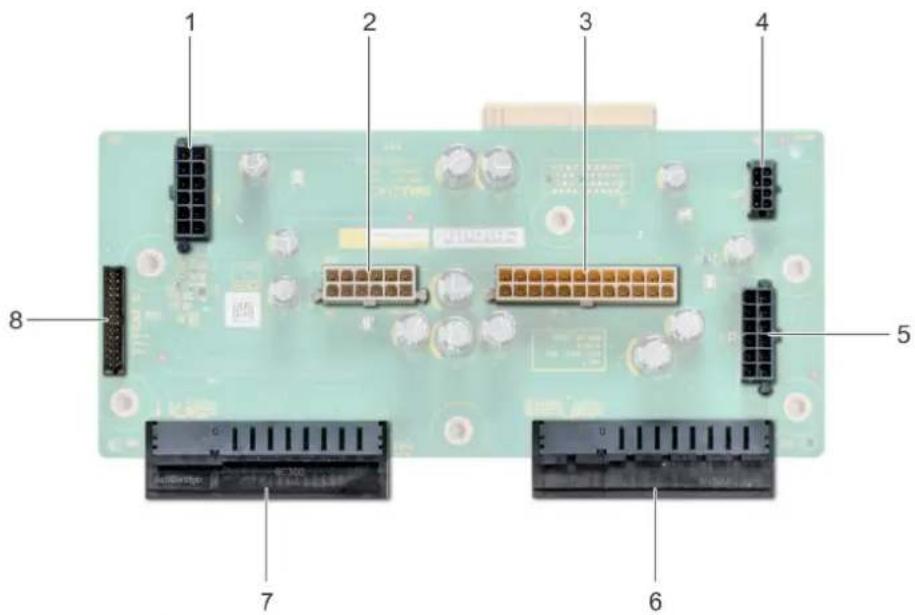
text_image
1 2 3 4 5 6 7 8Figure 114. Main power interposer board
- backplane 1 power connector [J_BP1] 2. backplane 0 power connector [J5]
- P2 power connector [J3] 4. P1 power connector [J_BP0]
- backplane 2 power connector [J_BP2] 6. PSU 1 connector
- PSU 2 connector 8. signal cable connector [J4]

text_image
1 2 3 4 5Figure 115. GPU power interposer board
- GPU power connector [J_GPU_POWER_225W_J4] 2. GPU power connector [J_GPU_POWER_225W_J5]
- GPU power connector [J_GPU_POWER_225W_J3] 4. GPU power connector [J_GPU_POWER_225W_J2]
- main power interposer board link connector
Removing the GPU power interposer board
Prerequisites
- Follow the safety guidelines listed in Safety instructions.
- Follow the procedure listed in Before working inside your system.
-
Remove the power supply units (PSUs).
-
Remove the system board.
Steps
- Lift the release pin, and slide the power interposer board (PIB) to release the board from the guide pin.
- Disengage the GPU PIB from the guide pins and lift the PIB out of the system.

natural_image
3D rendering of a server rack with internal circuit board and highlighted components (no text or symbols visible)Figure 116. Removing the GPU power interposer board
Next steps
- Install the GPU power interposer board.
Installing the GPU power interposer board
Prerequisites
Follow the safety guidelines listed in Safety instructions.
Steps
- Align the guide slots on the GPU power interposer board (PIB) with the guide pins on the chassis.
- Slide the GPU PIB until the release pin locks into place and secures the PIB.
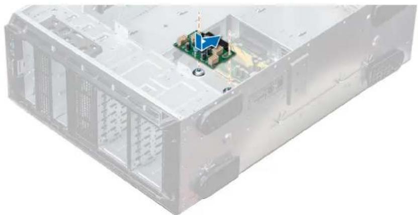
natural_image
3D rendering of a server rack with an internal circuit board and a blue arrow indicating a component (no text or symbols visible)Figure 117. Installing the GPU power interposer board
Next steps
- Install the system board.
- Install the PSUs.
- Follow the procedure listed in After working inside your system.
Removing the main power interposer board
Prerequisites

CAUTION: To prevent damage to the main power interposer board (PIB), you must remove the power supply units (PSUs) from the system before removing the PIBs.
- Follow the safety guidelines listed in Safety instructions.
- Follow the procedure listed in Before working inside your system.
- Remove the PSUs.
- Remove the system board.
- If installed, remove the GPU PIB.
Steps
- Disconnect all the power cables from the main PIB.
- Using the Phillips #2 screwdriver, remove the screws that secure the main PIB to the system.
- Lift the main PIB out of the system.
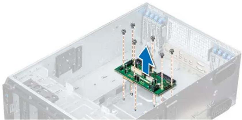
natural_image
3D illustration of a server room interior with a green circuit board and upward arrow, no text or symbols present.Figure 118. Removing the main PIB
Next steps
- Install the main power interposer board.
Installing the main power interposer board
Prerequisites
Follow the safety guidelines listed in Safety instructions.
Steps
- Align the screw holes on the main power interposer board (PIB) with the holes on the system chassis.
- Using the Phillips #2 screwdriver, secure the main PIB to the system using the screws.
- Connect all the disconnected power cables to the main PIB.

natural_image
3D illustration of a computer motherboard with a green circuit board and a blue downward arrow, no text or symbols present.Figure 119. Installing the main power interposer board
Next steps
- If removed, install the GPU PIB.
- Install the system board.
- Install the power supply units.
- Follow the procedure listed in After working inside your system.
Converting the system from tower mode to rack mode
Your system can be converted from the tower mode to the rack mode.
To convert your system from the tower mode to the rack mode, you require the tower to rack conversion kit, which contains the following:
- Rack ears (left and right) with three screws each
- VGA module
- VGA cable
- Rack slide cover
- Mylar cover
Converting the system from tower mode to rack mode
Prerequisites
- Follow the safety guidelines listed in Safety instructions.
- Follow the procedure listed in Before working inside your system.
- Lay the system on a flat, stable surface.
- Remove the system cover.
- If installed, remove the system feet or caster wheels.
Steps
- Remove the system top cover.
- Remove the control-panel assembly.
- Install the rack slide cover by performing the following steps:
a) Slide the rack slide cover between the system's side cover and the chassis.
b) Slide the rack slide cover toward the back of the system until the tabs on rack slide cover locks with the tabs extending from the chassis.
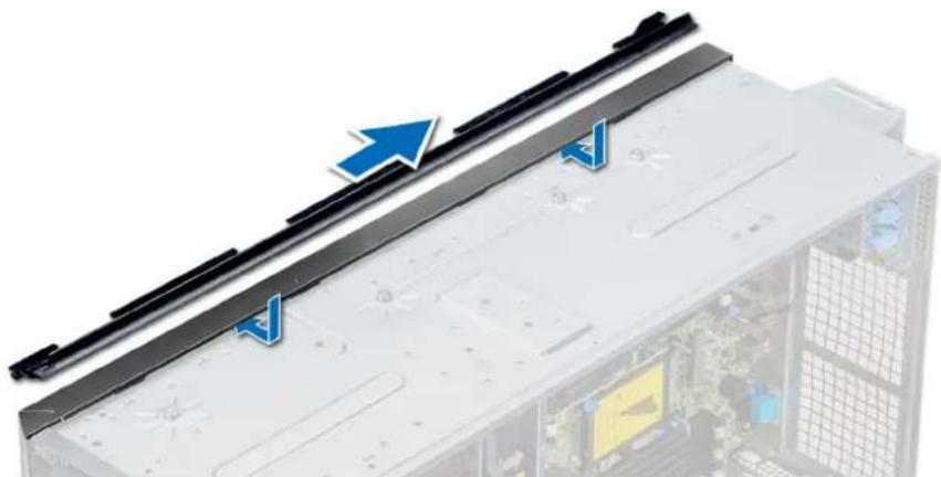
natural_image
Close-up of a server rack with blue directional arrows indicating movement or flow, no visible text or symbolsFigure 120. Installing the rack slide cover
-
Install the control panel assembly.
-
Attach the mylar to cover the screw hole on the chassis where one of the system rear feet was installed while in the tower mode.
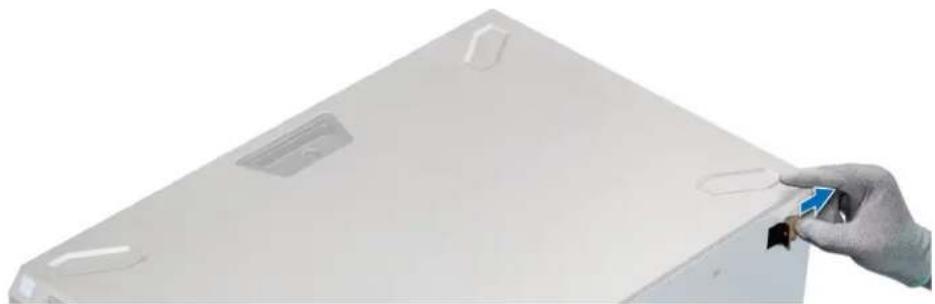
natural_image
Hand holding a small electronic component with a blue arrow, next to a white rectangular panel (no text or symbols visible)Figure 121. Attaching the mylar cover
- Install the rack ears by performing the following steps:
a) Align the three screw holes on the rack ears with the screw holes on the top and the bottom of system.
b) Using a Phillips #2 screwdriver, secure the rack ears to the system.

natural_image
Front view of a server rack with black connectors and mounting holes (no visible text or labels)Figure 122. Installing the system ears
Next steps
- Install the system cover.
- Install the system in the rack. For more information, see the Rack Installation Guide that is shipped with your system.
- Follow the procedure listed in After working inside your system.
System diagnostics
If you experience a problem with your system, run the system diagnostics before contacting Dell for technical assistance. The purpose of running system diagnostics is to test your system hardware without using additional equipment or risking data loss. If you are unable to fix the problem yourself, service and support personnel can use the diagnostics results to help you solve the problem.
Topics:
• Dell Embedded System Diagnostics
Dell Embedded System Diagnostics

NOTE: The Dell Embedded System Diagnostics is also known as Enhanced Pre-boot System Assessment (ePSA) diagnostics.
The Embedded System Diagnostics provides a set of options for particular device groups or devices allowing you to:
- Run tests automatically or in an interactive mode
- Repeat tests
- Display or save test results
- Run thorough tests to introduce additional test options to provide extra information about the failed device(s)
- View status messages that inform you if tests are completed successfully
• View error messages that inform you of problems encountered during testing
Running the Embedded System Diagnostics from Boot Manager
Run the Embedded System Diagnostics (ePSA) if your system does not boot.
Steps
- When the system is booting, press F11.
- Use the up arrow and down arrow keys to select System Utilities > Launch Diagnostics.
- Alternatively, when the system is booting, press F10, select Hardware Diagnostics > Run Hardware Diagnostics. The ePSA Pre-boot System Assessment window is displayed, listing all devices detected in the system. The diagnostics starts executing the tests on all the detected devices.
Results
Running the Embedded System Diagnostics from the Dell Lifecycle Controller
Steps
- As the system boots, press F10.
- Select Hardware Diagnostics → Run Hardware Diagnostics.
The ePSA Pre-boot System Assessment window is displayed, listing all devices detected in the system. The diagnostics starts executing the tests on all the detected devices.
System diagnostic controls
Menu Description
Configuration Displays the configuration and status information of all detected devices.
Results Displays the results of all tests that are run.
System health Provides the current overview of the system performance.
Event log
Displays a time-stamped log of the results of all tests run on the system. This is displayed if at least one event description is recorded.
Topics:
- Contacting Dell EMC
• Documentation feedback - Accessing system information by using QRL
- Receiving automated support with SupportAssist
• Recycling or End-of-Life service information
Contacting Dell EMC
Dell EMC provides several online and telephone based support and service options. If you do not have an active internet connection, you can find contact information about your purchase invoice, packing slip, bill, or Dell EMC product catalog. Availability varies by country and product, and some services may not be available in your area. To contact Dell EMC for sales, technical assistance, or customer service issues:
Steps
- Go to www.dell.com/support/home.
-
Select your country from the drop-down menu on the lower right corner of the page.
-
For customized support:
a) Enter your system Service Tag in the Enter your Service Tag field.
b) Click Submit.
The support page that lists the various support categories is displayed.
- For general support:
a) Select your product category.
b) Select your product segment.
c) Select your product.
The support page that lists the various support categories is displayed.
- For contact details of Dell EMC Global Technical Support:
a) Click Global Technical Support.
b) The Contact Technical Support page is displayed with details to call, chat, or e-mail the Dell EMC Global Technical Support team.
Documentation feedback
You can rate the documentation or write your feedback on any of our Dell EMC documentation pages and click Send Feedback to send your feedback.
Accessing system information by using QRL
You can use the Quick Resource Locator (QRL) located on the information tag in the front of the T640, to access the information about the Dell EMC PowerEdge T640.
Prerequisites
Ensure that your smartphone or tablet has the QR code scanner installed.
The QRL includes the following information about your system:
- How-to videos
• Reference materials, including the Installation and Service Manual, and mechanical overview - Your system service tag to quickly access your specific hardware configuration and warranty information
• A direct link to Dell to contact technical assistance and sales teams
Steps
- Go to www.dell.com/qrl and navigate to your specific product or
- Use your smartphone or tablet to scan the model-specific Quick Resource (QR) code on your system or in the Quick Resource Locator section.
Quick Resource Locator for PowerEdge T640

text_image
Hand holding smartphone displaying QR code, with a separate QR code shown on screen
text_image
Quick Resource Locator www.dell.com/QRL/Server/PET640Figure 123. Quick Resource Locator for PowerEdge T640
Receiving automated support with SupportAssist
Dell EMC SupportAssist is an optional Dell EMC Services offering that automates technical support for your Dell EMC server, storage, and networking devices. By installing and setting up a SupportAssist application in your IT environment, you can receive the following benefits:
- Automated issue detection — SupportAssist monitors your Dell EMC devices and automatically detects hardware issues, both proactively and predictively.
- Automated case creation — When an issue is detected, SupportAssist automatically opens a support case with Dell EMC Technical Support.
- Automated diagnostic collection — SupportAssist automatically collects system state information from your devices and uploads it securely to Dell EMC. This information is used by Dell EMC Technical Support to troubleshoot the issue.
• Proactive contact — A Dell EMC Technical Support agent contacts you about the support case and helps you resolve the issue.
The available benefits vary depending on the Dell EMC Service entitlement purchased for your device. For more information about SupportAssist, go to www.dell.com/supportassist.
Recycling or End-of-Life service information
Take back and recycling services are offered for this product in certain countries. If you want to dispose of system components, visit www.dell.com/recyclingworldwide and select the relevant country.