MOD-32 - Matrice modulaire CYP - Free user manual and instructions
Find the device manual for free MOD-32 CYP in PDF.

User questions about MOD-32 CYP
0 question about this device. Answer the ones you know or ask your own.
Ask a new question about this device
Download the instructions for your Matrice modulaire in PDF format for free! Find your manual MOD-32 - CYP and take your electronic device back in hand. On this page are published all the documents necessary for the use of your device. MOD-32 by CYP.
USER MANUAL MOD-32 CYP
The information in this manual has been carefully checked and is believed to be accurate. CYP (UK) Ltd assumes no responsibility for any infringements of patents or other rights of third parties which may result from its use.
CYP (UK) Ltd assumes no responsibility for any inaccuracies that may be contained in this document. CYP (UK) Ltd also makes no commitment to update or to keep current the information contained in this document.
CYP (UK) Ltd reserves the right to make improvements to this document and/or product at any time and without notice.
COPYRIGHT NOTICE
No part of this document may be reproduced, transmitted, transcribed, stored in a retrieval system, or any of its part translated into any language or computer file, in any form or by any means—electronic, mechanical, magnetic, optical, chemical, manual, or otherwise—without express written permission and consent from CYP (UK) Ltd.
© Copyright 2011 by CYP (UK) Ltd.
All Rights Reserved.
Version 1.1 August 2011
TRADEMARK ACKNOWLEDGMENTS
All products or service names mentioned in this document may be trademarks of the companies with which they are associated.
SAFETY PRECAUTIONS
Please read all instructions before attempting to unpack, install or operate this equipment and before connecting the power supply.
Please keep the following in mind as you unpack and install this equipment:
- Always follow basic safety precautions to reduce the risk of fire, electrical shock and injury to persons.
- To prevent fire or shock hazard, do not expose the unit to rain, moisture or install this product near water.
- Never spill liquid of any kind on or into this product.
- Never push an object of any kind into this product through any openings or empty slots in the unit, as you may damage parts inside the unit.
- Do not attach the power supply cabling to building surfaces.
- Use only the supplied power supply unit (PSU). Do not use the PSU if it is damaged.
- Do not allow anything to rest on the power cabling or allow any weight to be placed upon it or any person walk on it.
- To protect the unit from overheating, do not block any vents or openings in the unit housing that provide ventilation and allow for sufficient space for air to circulate around the unit.
REVISION HISTORY
| VERSION NO. DATE SUMMARY OF CHANGE | ||
| v1.00 03/03/2015 First release | ||
| v1.01 25/03/2015 Added Modules Diagram | ||
| v1.02 07/04/2015 Added IR Remote & Pin-out Sections | ||
| v1.03 27/05/2015 Added note about IP values | ||
CONTENTS
- Introduction......6
- Applications 6
- Package Contents 6
- System Requirements 7
-
Features......7
-
Operation Controls and Functions......8
6.1 Front Panel 8
6.2 Rear Panel....10
6.3 RS-232 Protocols....11
6.4 Remote Control....12
6.5 IR Cable Pin Assignment ....13
6.6 RS-232 & Telnet Command....14
6.7 RS-232 & IP to RS-232 RX Output Configuration ..... 16
6.8 Telnet Control....17
6.9 Web GUI Control ....19
- Connection Diagram ......21
7.1 Example installation (32x32 HDMI Matrix)......21
7.2 Input and Output Modules 22
- Specifications....23
8.1 Technical Specifications (Enclosure)....23
8.2 Technical Specifications (Input Modules) ......24
8.3 Technical Specifications (Output Modules)......25
8.4 CAT5e/6/7 Cable Specification ....27
- Acronyms....28
1. INTRODUCTION
The 32x32 Modular Matrix is designed to allow the switching and distribution of up to 32 source devices to up to 32 connected displays, either directly via HDMI, DVI or via CAT5e/6/7 outputs to compatible receivers, providing control options (dependent on module configuration).
Providing unparalleled levels of flexibility, with an advanced modular design these models can be setup in a wide variety of combinations allowing users the ability to tailor the Matrix to their requirements by simply adding or removing the input or output modules as required.
The Modular Matrix is supplied with dual removable internal PSU's which allow for easy inspection and maintenance with zero down time. Also included is a DVI output for local monitoring of the output allowing installers to easily monitor, test, and configure the Inputs and Outputs on installation
In addition, this matrix also features IP control allowing users to access and control the matrix remotely and also allow additional options for integration of third-party control systems
2. APPLICATIONS
■ Public information display
Educational demo
Professional Presentation
Advertising display
3. PACKAGE CONTENTS
32x32 Modular Matrix Enclosure (including CPU control board & Removeable dual power supplies)
4× Input Module Boards - HDMI/DVI/CAT5e/6/7 or VGA (Optional)
4× Output Module Boards - HDMI/DVI/CAT5e/6/7 (Optional)
1× IR Blaster
2× IR Extender
2× Power Cords
Operation manual
4. SYSTEM REQUIREMENTS
Up to 32 HDMI/DVI/CAT5e/6/7 or VGA source devices (dependent on module configuration) connected with appropriate cables.
Up to 32 displays (TV or monitor) or AV receivers, equipped with HDMI/DVI/CAT5e/6/7 connection (dependent on module configuration) connected with appropriate cables
Industry standard CAT5e/6/7 cable (for CAT5e/6/7 inputs/outputs)
Compatible PoC HDBaseT™ Transmitters/Receivers for CAT5e/6/7 Input/Output modules
5. FEATURES
HDMI, HDCP 1.1 and DVI 1.0 compliant
Interchangeable input and output modules
Input and output module types can be mixed and added in multiples of 8 from 8x8 (1 Input module, 1 Output module) up to 32x32 (4 Input modules, 4 Output modules) with HDMI, DVI, CAT5e/6/7 and VGA (Input Only) connection types
Supports passthrough of LPCM 7.1CH, Dolby TrueHD, Dolby Digital Plus and DTS-HD Master Audio
Supports a wide range of PC and HDTV resolutions from VGA to WUXGA and 480i to 1080p and 4Kx2K (dependent on module configuration)
Supports control of the matrix via IR, RS-232, Telnet and Web GUI controls
Dual removable power supply units, supports replacement without any matrix downtime
Supports HDMI cable input and output lengths of up to 15m each way (1080p@8bit resolution) or 10m (1080p@12bit resolution)
Support 3 EDID modes:
- Standard mode: Factory Default
- Automatic mode: reads the EDID settings from the display connected to the lowest numbered output port
- Manual mode: Can assign any input to any output port
Supports CAT5e/6/7 cable input and output lengths of up to 100m (1080p) or 70m (4Kx2K) dependent on module configuration
5Play convergence: HD Video, HD Audio, PoC, Ethernet & Control (IR & RS-232)
4Play convergence: Video, Audio, PoC & Control (IR & RS-232)
3Play convergence: Video, Audio & Control (IR & RS-232)
6. OPERATION CONTROLS AND FUNCTIONS
6.1 Front Panel
flowchart
graph TD
    A["1"] --> B["Blue Box"]
    C["2"] --> D["Power"]
    D --> E["RE"]
    E --> F["RN"]
    F --> G["MENU"]
    G --> H["7"]
    H --> I["6"]
    I --> J["9"]
    J --> K["LOCK"]
    L["3"] --> M["PAGE"]
    M --> N["PAGE"]
    N --> O["ALL"]
    O --> P["OUTIN"]
    P --> Q["0"]
    Q --> R["+"]
    R --> S["ENTER"]
    T["4"] --> U["PAGE"]
    U --> V["ALL"]
    V --> W["OUTIN"]
    W --> X["0"]
    X --> Y["+"]
    Y --> Z["ENTER"]
    AA["5"] --> AB["PAGE"]
    AB --> AC["MENU"]
    AC --> AD["7"]
    AD --> AE["6"]
    AE --> AF["9"]
    AF --> AG["LOCK"]
    AH["68"] --> AI["●"]
    AI --> AJ["●"]
    AJ --> AK["●"]
    AK --> AL["●"]
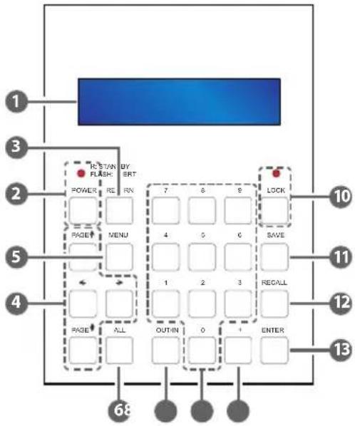
1 LCM: Displays the setting information of each input/output and other setting information according to the selected mode.
2 POWER button & LED: Press this button to turn the device ON or press it again to put the device into standby mode. The LED will illuminate when the unit is in standby mode.
Note: If the LED is flashing it means the temperature inside is too high and air circulation may have been restricted.
3 RETURN: Press this button to return back or exit the current selection.
4 PAGE ▲ ▼ ◀▶: Use these buttons to cycle through the LCM's options for displaying the current I/O status or when entering into the settings menu.
5 MENU: Press this button to enter the menu to change the following settings:
A. EDID
- Standard Mode: Uses the built-in EDID settings that support video up to 1080p@60/WUXGA@60RB and LPCM 2CH audio
- Automatic Mode: Reads the EDID settings from the display connected to the lowest numbered output port.
- Manual Mode: Supports independent EDID settings by selecting the input and output ports.
B. IP Settings
- IP address
- IP Netmask
- IP Gateway
Note: For display only, these values can only be changed in the Web GUI or via RS-232/Telnet
C. Temperature
- Temperature 1
- Temperature 2
NOTE: these figures show the internal temperature of the device.
D. LCM Contrast Range from 1\~4
6 ALL: Press this button to assign the same input to all outputs.
7 0\~9: Use to select the appropriate numbered input or output.
8 OUT/IN: Press to assign the source to be displayed on the required output. The sequence should be OUT/IN→Select the Input→OUT/IN→Select the output→Enter.
9 + (Plus): Press this button when multiple outputs are required for a selected input. This button only works in conjunction with the OUT/IN button.
10 LOCK button & LED: Press this button to lock all the function buttons on panel. The LED will illuminate, to unlock press it again.
11 SAVE: Press this button to store the present Input/Output configuration to one of the 8 available preset settings.
12 RECALL: Press this button to recall a previously stored preset setting.
13 ENTER: Press this button to confirm a setting or selection in the menu.
6.2 Rear Panel
text_image
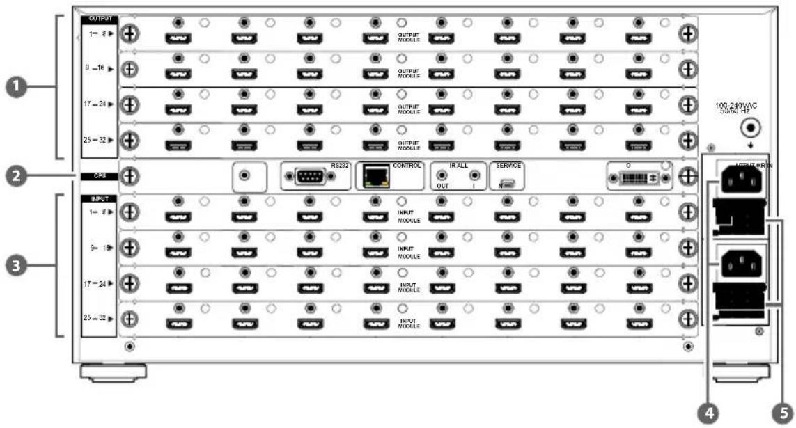
OUTPUT 1- 8 > 9 -16 > 17 -24 > 25 -32 > CPU INPUT 1- 8 > 9 - 18 > 17 -24 > 25 -32 > OUTPUT MODULES OUTPUT MODULES OUTPUT MODULES OUTPUT MODULES OUTPUT MODULES RS2321 CONTROL IR ALL SERVICE OUT I Service 0 OUTPUT ORIN 100-240VAC 50MHz Hz OUTPUT ORIN 4 5Note: The above panel is an example of a 32x32 HDMI configuration.
1 OUTPUTS 1\~32: Install up to 4 Output modules as required for up to 32 display or CAT5e/6/7 outputs (dependent on module configuration).
2 CPU (Control Board)
IR IN: For control of the matrix only. Connect to the IR extender for IR signal reception of the IR remote control of the matrix. Ensure that the remote being used is within the direct line-of-sight of the IR extender.
RS-232: Connect with a D-Sub 9-pin cable to a PC/Laptop device or RS-232 Control system for RS-232 control of the Matrix or RS-232 compatible devices connected to CAT5e/6/7 receivers.
CONTROL: Connect to an active network for LAN serving and Telnet/Web GUI control. (LAN serving on compatible HDBaseT input/output modules and transmitter/receivers only)
ALL IR OUT: Connect to the IR blaster for IR signal transmission of the source or display equipment. Place the IR blaster in direct line-of-sight of the equipment to be controlled.
ALL IR IN: Connect to the IR extender for IR signal reception of the remote control of this device or the source and display equipment. Ensure that remote being used is within the direct line-of-sight of the IR extender.
SERVICE: This port is reserved for firmware update only.
OUTPUT 0: Connect to DVI equipped display or to an HDMI equipped display (with DVI to HDMI adaptor) for local monitoring of the output signal.
3 INPUT 1\~32: Install up to 4 Input modules as required for connection to up to 32 source devices or CAT5e/6/7 inputs (dependent on module configuration).
4 POWER & POWER Supply: The device will automatically turn ON when connected to an active power supply.
5 Ventilation Fan: This fan will automatically operate when the device is switched ON. Do not block the exhaust of the fan or cover it with any object. Please allow adequate space around the unit for air to circulate freely.
6.3 RS-232 Protocols
| Matrix | RS-232 Controller | ||
| PIN Definition PIN Definition | |||
| 1 NC 1 NC | |||
| 2 TxD 2 RxD | |||
| 3 RxD 3 TxD | |||
| 4 NC 4 NC | |||
| 5 GND 5 GND | |||
| 6 NC 6 NC | |||
| 7 NC 7 NC | |||
| 8 NC 8 NC | |||
| 9 NC 9 NC | |||
Baud Rate: 19200bps
Data Bit: 8 bits
Parity: None
Stop Bit: 1
Flow Control: None
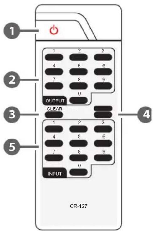
6.4 Remote Control
1 Power:
Press this button to switch on the device or set it to standby mode
2 OUTPUT:
Output port selection
3 CLEAR:
Press to clear the present input/output selection
4 ENTER:
Press to confirm the present input/output selection
5 INPUT:
Input port selection
IR Control:
From the front panel:
- Select the output zone (1–32)
- Select the input source (1–32)
- Press enter to confirm
From the zone:
- Select the input source (1–32)
- Press enter to confirm
text_image
1 OUTPUT CLEAR 4 1 2 3 4 5 6 7 8 9 0 INPUT CR-127 2 3 4 5 6 7 8 9 0 46.5 IR Cable Pin Assignment

text_image
IR Emitter 1 Power 5V 2 IR Blaster Signal 3 NC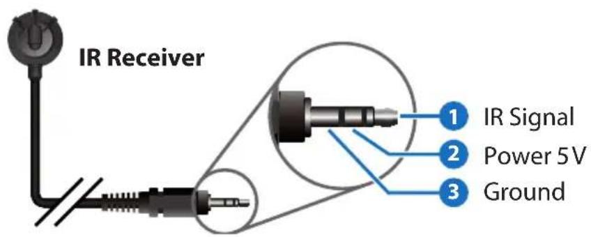
text_image
IR Receiver 1 IR Signal 2 Power 5V 3 Ground6.6 RS-232 & Telnet Command
HELP: Show Command list.
| Command Description | |
| P1 Power on. | |
| P0 Power off. | |
| Oxly Set Output (x:0~32) to Input (y:1~32). | |
| ALLOUT x Set all outputs to input (x:01~32). | |
| ACTIVE Report active I/O channels. | |
| INDETECT Input channels detection indicator. | |
| OUTDETECT Output channels detection indicator. | |
| PORTSTATUS Report all output connection status. | |
| HDCPON x Set input port(x:01~32) HDCP to ON. | |
| HDCPOFF x Set input port (x:01~32) HDCP to OFF. | |
| HDCPONALL Set ALL input port's HDCP to ON. | |
| HDCPOFFALL Set ALL Input port's HDCP to OFF. | |
| HDCPSTATUS Show the HDCP status of all outputs(0=disabled,1=enable). | |
| MUTEO x Mute video for output (x:0~32) | |
| UNMUTEO x Unmute video for output (x:0~32) | |
| MUTEI x | Mute video for input (x:0~32) |
| UNMUTEI x | Unmute video for output (x:0~32) |
| MUTEALL | Mute all outputs. |
| UNMUTEALL Unmute all inputs. | |
| MUTESTATUS Show the mute status of all outputs(0=unmuted,1=muted). | |
| HPDL x | Pull the input (x:01~32) Hot Plug Detect signal to 'LOW'. |
| HPDH x | Pull the input (x:01~32) Hot-Plug-Detect signal to 'HIGH'. |
| HPDLALL Set the Hot-Plug-Detect of all inputs to Low. | |
| HPDHALL Set the Hot-Plug-Detect of all inputs to High. | |
| HPDSTATUS Report the Hot-Plug-Detect signal status of all inputs. | |
| EDIDMODE x y Set the EDID mode of input (x: 01~32) to (y:1~2). | |
| EDIDMODEALL x The EDID mode of All Input to (x:1~2). | |
| EDIDPORT x y Set the EDID mode of Assigned Port (y:01~32) to Input( x:01~32). | |
| EDIDPORTALL x The EDID mode of All ports is assigned to Output (x:01-32). | |
| EDIDSTATUS Report the status of the EDID Modes of all input ports. | |
| UART x y "str" Write UART string to output port(x:in/out, y:01~32, "str":"string"). | |
| UARTBAUD x y Set the UART Baud rate of output port (x:01~32) (y:rate). | |
| STATUSUART Show output port UART baud rate. | |
| TEMPSTATUS Show temperature sensor values y1, y2. | |
| SETIPADDR | Set the IP address (x.x.x.x). |
| SETSNMASK | Set the subnet mask (x.x.x.x). |
| SETGWADDR | Set the gateway IP address (x.x.x.x). |
| IPCONFIG Display the current IP configuration. | |
| RSTIP | Reset the IP Configuration Reset To Default values (DHCP). |
| BUZZER x | Mute the Buzzer (mute=0, UnMute=1). |
| REBOOT | Reboot the System. |
| SAVETO x Save as Preset x(1~10). | |
| RECALLTO x Recall Preset x(1~10). | |
| RESET System Reset to | O1I1,O2I2,O3I3,O4I4,O5I5.... |
| VERSION Display controller firmware version. | |
Note: Commands will be not executed unless followed by a carriage return. Commands are not case-sensitive
6.7 RS-232 & IP to RS-232 RX Output Configuration
- To check the Baud rate of a port, the command is STATUSUART. (Default is 19200bps)
- To set the Baud rate, the command is UARTBAUD x y (x= output port 01\~32, y= Baud rate ), e.g to set the baud rate of Output 8 to 115200 bps you would send the command 'UARTBAUD 08 115200'.
- To send a string to the RX side, the command is UART x "y" (x= output port 01\~32, y= the string which you want to send to RX side), e.g. to send the string P0 to Output 12 you would send the command UART 12 "P0". In this example P0 is a common power command.
- You would use the same procedure for sending IP Telnet to RS-232 commands.
6.8 Telnet Control
Before attempting to use the telnet control, please ensure that both the Matrix (via the 'LAN /CONTROL' port) and the PC/Laptop are connected to the same active networks.
To access the telnet control in Windows 7, click on the 'Start' menu and type "cmd" in the Search field then press enter.
Under Windows XP go to the 'Start' menu and click on "Run", type "cmd" with then press enter.
Under Mac OS X, go to Go→Applications→Utilities→Terminal
See below for reference.

text_image
Remote Desktop Connection Skype Windows Live Messenger Microsoft Excel 2010 Sage 50 Accounts 2011 Picture Motion Browser Adobe Reader X Microsoft Word 2010 Sticky Notes Windows Media Center All Programs cmd programs and files Pictures Music Games Computer Control Panel Devices and Printers Default Programs Help and Support Shut down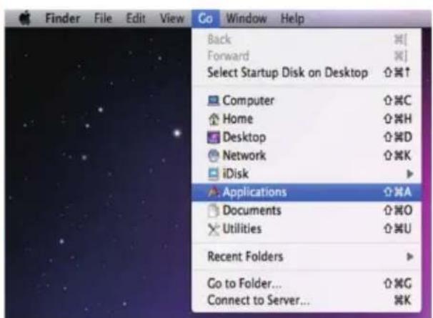
text_image
Finder File Edit View Go Window Help Back ⌘[ Forward ⌘] Select Startup Disk on Desktop ⌘↑ Computer ⌘C Home ⌘H Desktop ⌘D Network ⌘K iDisk Applications ⌘A Documents ⌘O Utilities ⌘U Recent Folders Go to Folder... ⌘G Connect to Server... ⌘KOnce in the command line interface (CLI) type "telnet", then the IP address of the unit and "23", then hit enter.
Note: The IP address of the Matrix can be displayed on the device's LCM monitor by pressing the Menu button twice.

text_image
Administrator: C:\Windows\system32\cmd.exe Microsoft Windows [Version 6.1.7600] Copyright (c) 2009 Microsoft Corporation. All rights reserved. C:\Users\CYP>telnet 192.168.5.80 23_This will bring us into the device which we wish to control. Type "HELP" to list the available commands.

text_image
Welcome to CYPRESS Matrix TELNET. celnet-> help P0 : Power Off P1 : Power On RESET : System Reset to 0111,0212,0313,0414,0515.... 0xxIxx(x:01~8) : Output 0~8 set to Input 1~8 ALLOUT xx(x:01~8) : All Output set to Input 1~8 MUTE xx(x:01~8) : Video mute command at output interface UNMUTE xx(x:01~8) : Video unmute command at output interface MUTEALL : Mute all outputs UNMUTEALL : Unmute all outputs SHOWMUTE : Show mute status of all output(0=not muted,1=muted) RDMUTE xx(x:01~8) : Read MUTE Status at Output HPDLOW xx(x:01~8) : Pull the Hot-Plug-Detect signal to 'LOW' HPDHIGH xx(x:01~8) : Pull the Hot-Plug-Detect signal to 'HIGH' HPDLOW ALL : Set All Input HPD to Low HPDHIGH ALL : Set All Input HPD to High SHOWMPD : Report ALL Input Hot-Plug-Detect signal status STATUSHPD x(x:1~8) : Show HPD status of input(x) SHOWTEMP : Show temperature sensor values y1, y2 STATUSIN xx(x:01~8) : Report Input connection status STATUSOUT xx(x:01~8) : Report Output connection status STATUSALL : Report ALL Output connection status STATUSEDID : Report ALL Input EDID mode&port SEIEDIDMODE ii mn(ii:01~8 nm:1~3) : Set EDID mode(nm) to Input(ii) SEIEDIDMODE ALL nm (nm-1~3) : The EDID mode(nm) of All Input(ii) SETEDIDPORT ii pp(ii:01~8 pp:01~8) : Set EDID Assigned Port(pp) to Input(ii) SETEDIDPORT ALL nm (pp=01-8) : The EDID of All Imports is assigned to Output PP ACTIVE : Report I/O active channels INDETECT : Input channels detect indicator OUTDETECT : Output channels detect indicator IPCONFIG : Display the current IP config SETIPType "IPCONFIG" To show all IP configurations. To reset the IP, type "RSTIP" and to use a static IP, type "SETIP" (For a full list of commands, see Section 6.4).
Note: Commands will not be executed unless followed by a carriage return. Commands are not case-sensitive. If the IP is changed then the IP Address required for Telnet access will also change accordingly.
6.9 Web GUI Control
On a PC/Laptop that is connected to the same active network as the Matrix, open a web browser and type the device's IP address on the web address entry bar. The browser will display the device's status, control and User setting pages.
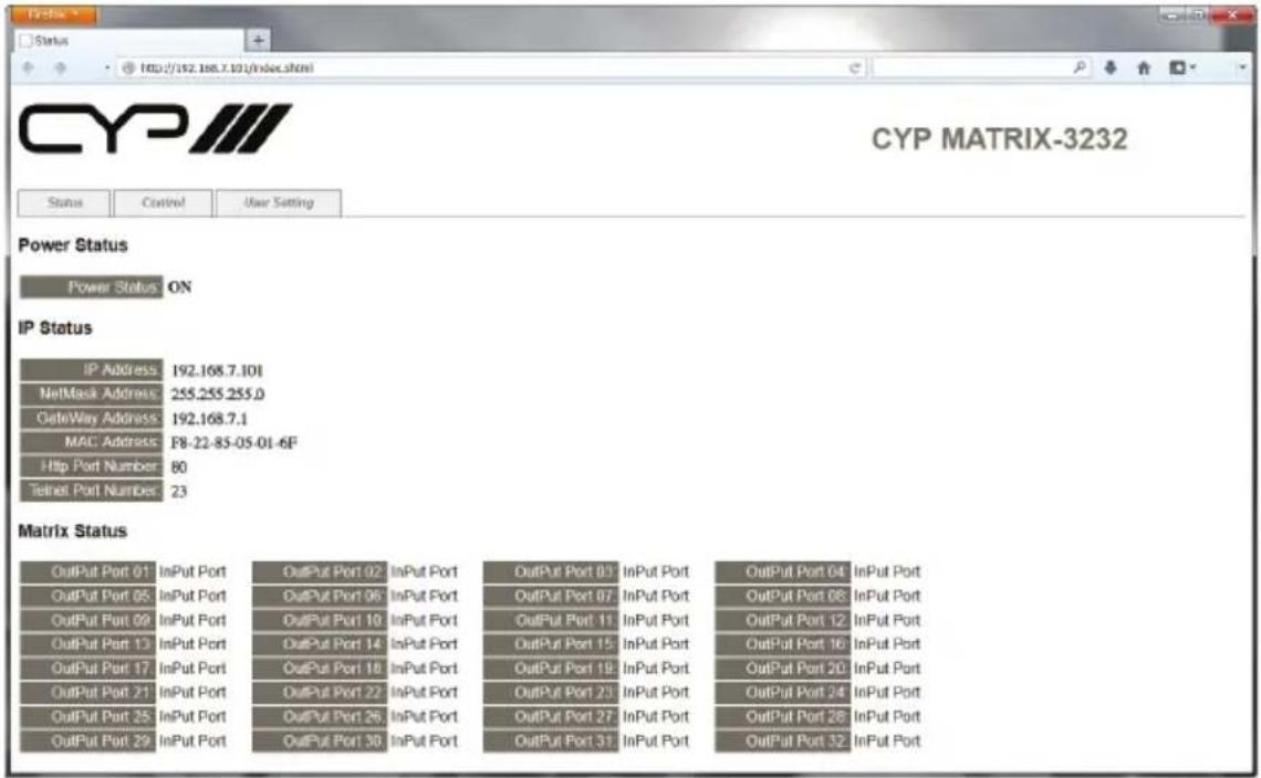
text_image
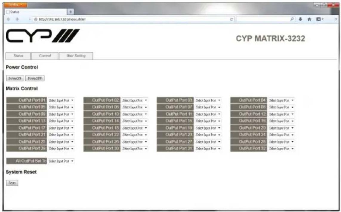
CYP MATRIX-3232 Status Control User Setting CYP MATRIX-3232 Power Status Power Status ON IP Status IP Address: 192.168.7.101 NetMask Address: 255.255.255.0 GateWay Address: 192.168.7.1 MAC Address: F8-22-85-05-01-6F Http Port Number: 80 Telnet Port Number: 23 Matrix Status OutPut Port 01 InPut Port OutPut Port 02 InPut Port OutPut Port 03 InPut Port OutPut Port 04 InPut Port OutPut Port 05 InPut Port OutPut Port 06 InPut Port OutPut Port 07 InPut Port OutPut Port 08 InPut Port OutPut Port 09 InPut Port OutPut Port 10 InPut Port OutPut Port 11 InPut Port OutPut Port 12 InPut Port OutPut Port 13 InPut Port OutPut Port 14 InPut Port OutPut Port 15 InPut Port OutPut Port 16 InPut Port OutPut Port 17 InPut Port OutPut Port 18 InPut Port OutPut Port 19 InPut Port OutPut Port 20 InPut Port OutPut Port 21 InPut Port OutPut Port 22 InPut Port OutPut Port 23 InPut Port OutPut Port 24 InPut Port OutPut Port 25 InPut Port OutPut Port 26 InPut Port OutPut Port 27 InPut Port OutPut Port 28 InPut Port OutPut Port 29 InPut Port OutPut Port 30 InPut Port OutPut Port 31 InPut Port OutPut Port 32 InPut PortClick on the 'Control' tab to control power, input/output ports, EDID and reset mode.
text_image
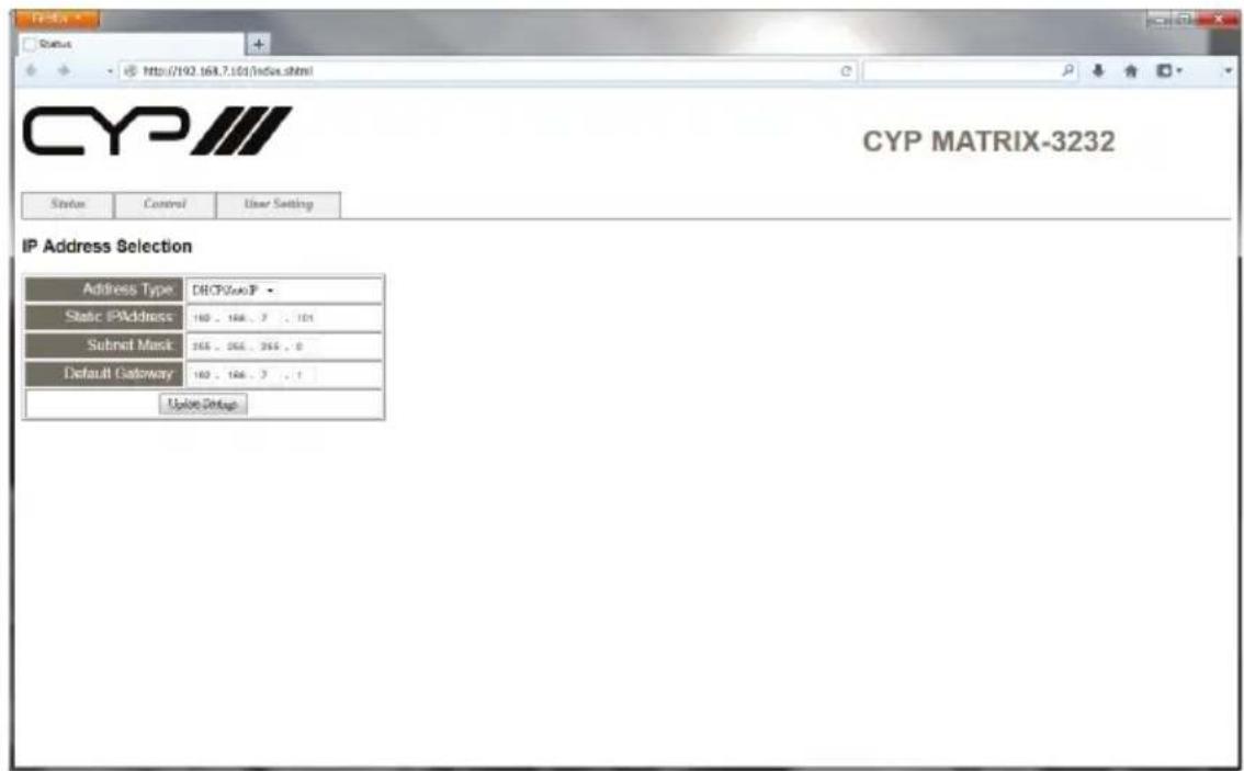
CYP MATRIX-3232 IP Address Selection Address Type DHCP/XP Static IPAddress 160, 166, 7, 101 Submit Mask 366, 366, 366, 0 Default Gateway 160, 166, 7, 1 Update SettingsClicking on the 'User Setting' tab allows you to reset the IP configuration. The system will ask for a reboot of the device each time any of the settings are changed. The IP address needed to access the Web GUI control will also need to be changed accordingly on the web address entry bar.
text_image
CYP MATRIX-3232 Power Control EventON EventOFT Matrix Control OutPut Port 01 Select Input Port Select Input Port Select Output Port Select Output Port Select Output Port Select Output Port Select Output Port Select Output Port Select Output Port Select Output Port Select Output Port Select Output Port Select Output Port Select Output Port Select Output Port Select Output Port Select Output Port Select Output Port Select Output Port Select Output Port Select Output Port Select Output Port Select Output Port Select Output Port Select Output Port Select Output Port Select Output Port Select Output Port Select Output Port Select Output Port Select Output Port Select Output Port Select Output Port Select Output Port Select Output Port Select Output OutPut Port 05 Select Input Port Select Input Port Select Input Port Select Input Port Select Input Port Select Input Port Select Input Port Select Input Port Select Input Port Select Input Port Select Input Port Select Input Port Select Input Port Select Input Port Select Input Port Select Input Port Select Input Port Select Input Port Select Input Port Select Input Port Select Input Port Select Input Port Select Input Port Select Input Port Select Input Port Select Input Port Select Input Port Select Input Port Select Input Port Select Input Port Select Input Port Select Input Port Select Input Port Select Input Port OutPut Port 09 Select Input Port Select Input Port Select Input Port Select Input Port Select Input Port Select Input Port Select Input Port Select Input Port Select Input Port Select Input Port Select Input Port Select Input Port Select Input Port Select Input Port Select Input Port Select Input Port Select Input Port Select Input Port Select Input Port Select Input Port Select Input Port Select Input Port Select Input Port Select Input Port Select Input Port Select Input Port Select Input Port Select Input Port Select Input Port Select Input Port Select Input Port Select Input Port Select Input Port OutPut Port 13 Select Input Port Select Input Port Select Input Port Select Input Port Select Input Port Select Input Port Select Input Port Select Input Port Select Input Port Select Input Port Select Input Port OutPut Port 17 Select Input Port Select Input Port Select Input Port Select Input Port Select Input Port Select Input Port Select Input Port OutPut Port 21 OutPut Port 25 OutPut Port 29 OutPut Port 30 OutPut Port 31 OutPut Port 32 OutPut Port 33 OutPut Port 34 OutPut Port 35 OutPut Port 36 OutPut Port 37 OutPut Port 38 OutPut Port 39 OutPut Port 40 OutPut Port 41 OutPut Port 42 OutPut Port 43 OutPut Port 44 OutPut Port 45 OutPut Port 46 OutPut Port 47 OutPut Port 48 OutPut Port 49 OutPut Port 50 OutPut Port 51 OutPut Port 52 OutPut Port 53 OutPut Port 54 OutPut Port 55 OutPut Port 56 OutPut Port 57 OutPut Port 58 OutPut Port 59 OutPut Port 60 OutPut Port 61 OutPut Port 62 OutPut Port 63 OutPut Port 64 OutPut Port 65 OutPut Port 66 OutPut Port 67 OutPut Port 68 OutPut Port 69 OutPut Port 70 OutPut Port 71 OutPut Port 72 OutPut Port 73 OutPut Port 74 OutPut Port 75 OutPut Port 76 OutPut Port 77 OutPut Port 78 OutPut Port 79 OutPut Port 80 OutPut Port 81 OutPut Port 82 OutPut Port 83 OutPut Port 84 OutPut Port 85 OutPut Port 86 OutPut Port 87 OutPut Port 88 OutPut Port 89 OutPut Port 90 OutPut Port 91 OutPut Port 92 OutPut Port 93 OutPut Port 94 OutPut Port 95 OutPut Port 96 OutPut Port 97 OutPut Port 98 OutPut Port 99 OutPut Port 100 All OutPut Set To: Select Input Post System Reset Reset7. CONNECTION DIAGRAM
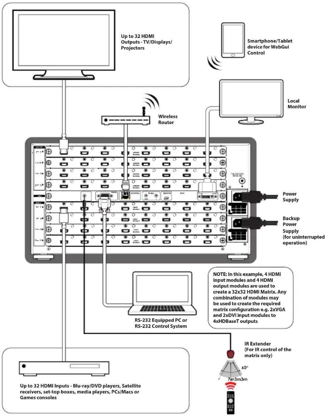
7.1 Example installation (32x32 HDMI Matrix)
flowchart
graph TD
    A["Up to 32 HDMI Outputs - TV/Displays/Projectors"] --> B["Wireless Router"]
    C["Smartphone/Tablet device for WebGui Control"] --> B
    D["Local Monitor"] --> B
    B --> E["RS-232 Equipped PC or RS-232 Control System"]
    E --> F["IR Extender (For IR control of the matrix only)"]
    F --> G["60°"]
    G --> H["7m3m3m"]
    style A fill:#f9f,stroke:#333
    style C fill:#f9f,stroke:#333
    style D fill:#f9f,stroke:#333
    style E fill:#ccf,stroke:#333
    style F fill:#ccf,stroke:#333
    style G fill:#cfc,stroke:#333
    style H fill:#fcc,stroke:#333
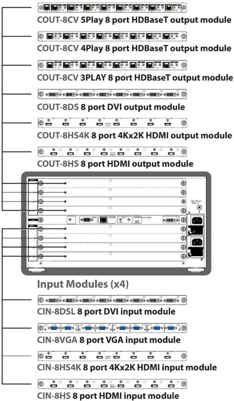
7.2 Input and Output Modules
Output Modules (x4)
text_image
COUT-8CV 5Play 8 port HDBaseT output module COUT-8CV 4Play 8 port HDBaseT output module COUT-8CV 3PLAY 8 port HDBaseT output module COUT-8DS 8 port DVI output module COUT-8HS4K 8 port 4Kx2K HDMI output module COUT-8HS 8 port HDMI output module Input Modules (x4) CIN-8DSL 8 port DVI input module CIN-8VGA 8 port VGA input module CIN-8HS4K 8 port 4Kx2K HDMI input module CIN-8HS 8 port HDMI input module8. SPECIFICATIONS
8.1 Technical Specifications (Enclosure)
Input ports Up to 32× HDMI or DVI or CAT5e/6/7 or VGA )
dependent on module configuration
Output ports Up to 32× HDMI or DVI or CAT5e/6/7
dependent on module on module
configuration
Power Supply 2× AC 110\~240V (US/EU standards,
CE/FCC/UL certified)
HMDI Cable I/O Distance 15m/8-bits, 10m/12-bits
Dimensions 482(W) × 494(D) × 233(H)
Weight 15 kg
Chassis Material Metal
Colour Black
Operating Temperature 0 °C\~40 °C/32 °F\~104 °F
Storage Temperature -20^ 60^ / -4^ 140^
Relative Humidity 20\~90 % RH (non-condensing)
Power Consumption 230W
8.2 Technical Specifications (Input Modules)
| IN-HDMI-8 8 Port HDMI Input Module | |
| Video Bandwidth 225MHz/6.75Gbps | |
| Input ports 8× HDMI | |
| Video resolutions PC: VGA ~WUXGA@60RB HD: 480i~1080p | |
| Audio transmission LPCM | 7.1CH, Dolby TrueHD, Dolby Digital Plus, DTS-HD Master Audio (32~192KHz Fs sample rate) |
| IN-DVI8 8 Port DVI input module | |
| Video Bandwidth 225MHz/6.75Gbps | |
| Input ports 8× DVI | |
| Video resolutions PC: VGA ~WUXGA@60RB HD: 480i~1080p | |
| Audio transmission LPCM | 7.1CH, Dolby TrueHD, Dolby Digital Plus, DTS-HD Master Audio (32~192KHz Fs sample rate) |
| IN-VGA8 8 Port VGA input module | |
| Input ports 8× VGA, 8× 2.5mm Audio phone jack | |
| Video resolutions PC: VGA ~WUXGA@60RB | |
| Audio transmission Stereo 2.5mm phone jack (included 2.5mm to 3.5mm adaptor) |
| IN-HDMI-4K-8 8 Port 4Kx2K HDMI input module | |
| Video Bandwidth 25~340MHz | |
| Input ports 8× HDMI | |
| Video resolutions PC: VGA ~WUXGAHD: 480i~1080p, 4Kx2K@30Hz, 4Kx2K@50/60 (4:2:0) | |
| Audio transmission LPCM7.1CH, Dolby TrueHD, Dolby Digital Plus,DTS-HD Master Audio (32~192KHz Fs sample rate) | |
8.3 Technical Specifications (Output Modules)
| OUT-HDMI-8 8 Port HDMI output module | |
| Video Bandwidth 225MHz/6.75Gbps | |
| Input ports 8× HDMI | |
| Video resolutions PC: VGA ~WUXGA@60RB HD: 480i~1080p | |
| Audio transmission LPCM7.1CH, Dolby TrueHD, Dolby Digital Plus,DTS-HD Master Audio (32~192KHz Fs sample rate) | |
| OUT-DVI8 8 Port DVI output module | |
| Video Bandwidth 225MHz/6.75Gbps | |
| Output ports 8× DVI | |
| Video resolutions PC: VGA ~WUXGA@60RB HD: 480i~1080p | |
| Audio transmission LPCM | 7.1CH, Dolby TrueHD, Dolby Digital Plus,DTS-HD Master Audio (32~192KHz Fs sample rate) |
| OUT-HDMI-4K-8 8 Port 4Kx2K HDMI output module | |
| Video Bandwidth 25~340MHz | |
| Output ports 8× HDMI | |
| Video resolutions PC: VGA ~WUXGAHD: 480i~1080p, 4Kx2K@30Hz, 4Kx2K@50/60 (4:2:0) | |
| Audio transmission LPCM7.1CH, Dolby TrueHD, Dolby Digital Plus,DTS-HD Master Audio (32~192KHz Fs samplerate) | |
| OUT-HBT3P-8 8 Port HDBaseT output module | |
| Video Bandwidth 225MHz/6.75Gbps | |
| Features Support HDBaseT/IR/RS232 | |
| Output ports 8× CAT5e/6, 8× IR Extender, 8× IR Blaster | |
| Video resolutions PC: VGA ~ WUXGA HD: 480i~1080p | |
| IR Frequency 30~50Hz | |
| Audio transmission LPCM | 7.1CH, Dolby TrueHD, Dolby Digital Plus,DTS-HD Master Audio (32~192KHz Fs samplerate) |
| OUT-HBT4P-8 8 Port HDBaseT output module | |
| Video Bandwidth 225MHz/6.75Gbps | |
| Features Support HDBaseT/PoC/IR/RS232 | |
| Output ports 8× CAT5e/6, 8× IR Extender, 8× IR Blaster | |
| IR Frequency 30~50Hz | |
| Video resolutions PC: VGA ~ WUXGA HD: 480i~1080p | |
| Audio transmission LPCM7.1CH, Dolby TrueHD, Dolby Digital Plus, DTS-HD Master Audio (32~192KHz Fs samplerate) | |
| OUT-HDBT-4K-8 8 Port HDBaseT output module | |
| Video Bandwidth 300MHz | /10.2Gbps |
| Features Support HDBaseT/PoC/IR/RS232/Ethernet | |
| Output ports 8× CAT5e/6, 8× IR Extender, 8× IR Blaster, 1× LAN | |
| Ethernet Speed 100Mbps | |
| Video resolutions PC: VGA ~WUXGA HD: 480i~1080p, 4Kx2K@30HzHD: 480i~1080p, 4Kx2K@30Hz, 4Kx2K@50/60 (4:2:0) | |
| IR Frequency 30~50Hz | |
| Audio transmission LPCM | 7.1CH, Dolby TrueHD, Dolby Digital Plus,DTS-HD Master Audio (32~192KHz Fs sample rate) |
8.4 CAT5e/6/7 Cable Specification
OUT-HBT3P-8 CABLE DISTANCE
| Cable Type | Range Pixel clock rate | Video Data Rate | Supported Video | |
| CAT5E/6/7 60 | m <=225 | MHz <=5.3 Gbps(HD Video) | Up to 1080p, 60 Hz, 36 bits, 3D (data rates lower than 5.3 Gbps or below 225 MHz TMDS clock). | |
OUT-HBT4P-8/OUT-HBT5P-4K-8 CABLE DISTANCE
| Cable Type | Range Pixel clock rate | Video Data Rate | Supported Video | |
| CAT5E/6/7 | 100 m <=22 | 5 MHz <=5.3 Gbps(HD Video) | Up to 1080p, 60 Hz, 36 bits, 3D (data rates lower than 5.3 Gbps or below 225 MHz TMDS clock). | |
| 70 m >22 | 5 MHz >5.3 Gbps(Ultra HD Video) | 4K2K, 30Hz video & 4Kx2K@50/60 (4:2:0) formats | ||
9. ACRONYMS
| ACRONYM COMPLETE TERM | |
| CLI Command Line Interface | |
| DTS Digital Theater System | |
| DVI Digital Visual Interface | |
| EDID Extended Display Identification Data | |
| GUI Graphical User Interface | |
| HDCP High-bandwidth Digital Content Protection | |
| HDMI High-Definition Multimedia Interface | |
| HDTV High-Definition Television | |
| LCM Liquid Crystal Module | |
| PoC Power over Cable | |
| VGA Video Graphics Array | |
| WUXGA Widescreen Ultra Extended Graphics Array |

CYP (UK) Ltd., Unit 7, Shepperton Business Park, Govett Avenue, Shepperton, Middlesex, TW17 8BA
Tel: +44 (0) 20 3137 9180 | Fax: +44 (0) 20 3137 6279
Email: sales@cypeurope.com
www.cypeurope.com
v1.03