40846 - Projector accessory Lindy - Free user manual and instructions
Find the device manual for free 40846 Lindy in PDF.

User questions about 40846 Lindy
0 question about this device. Answer the ones you know or ask your own.
Ask a new question about this device
Download the instructions for your Projector accessory in PDF format for free! Find your manual 40846 - Lindy and take your electronic device back in hand. On this page are published all the documents necessary for the use of your device. 40846 by Lindy.
USER MANUAL 40846 Lindy
Modular Projector Brackets
Manual
English
natural_image
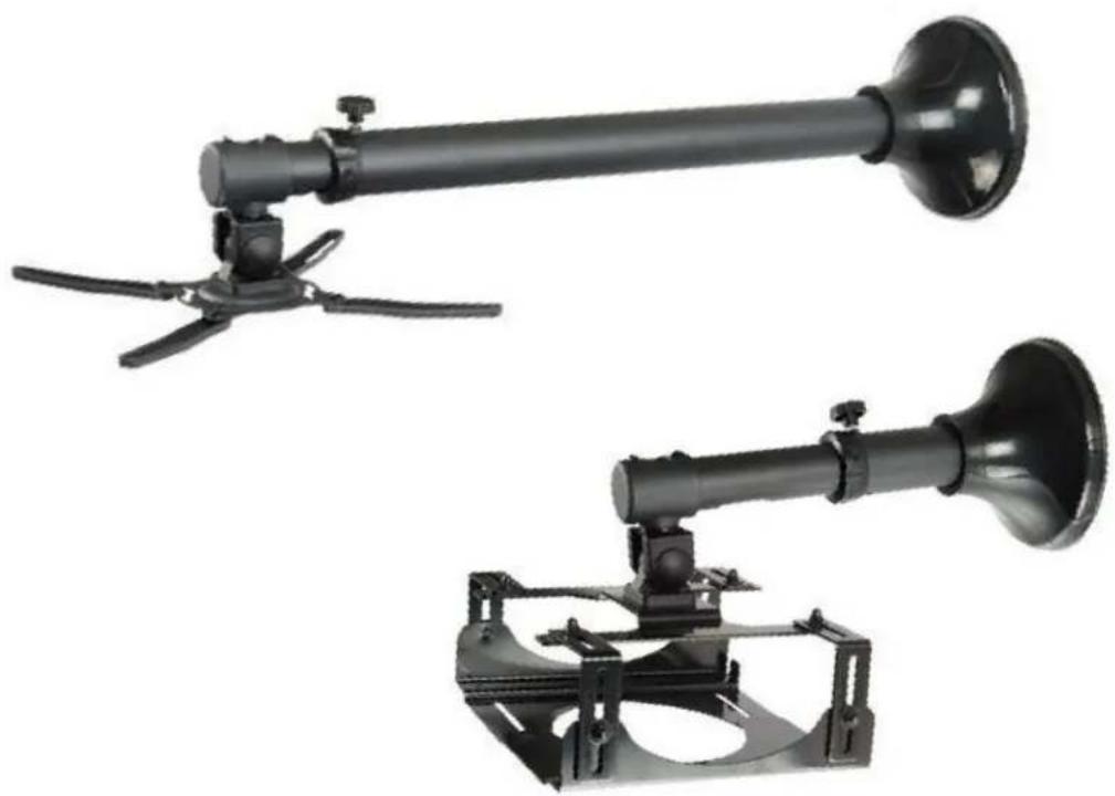
Two black industrial spray gun holders with propellers and mounting brackets, shown against a white background (no text or symbols visible)LINDY No. 40846, 40847, 40848 & 40849
www.lindy.com
Thank you for purchasing the LINDY modular solution for mounting projectors in your home, office or AV multimedia setup. Both products are universal and can support most projectors up to a weight of 11.5Kg. The brackets and poles all have the same black finish and also have the added benefit of a cable management system built in to the poles.
This manual will show you how to assemble and adjust both types of bracket using either the long or short pole. Please take note of the maximum weights supported by the brackets to avoid any damage to your installation or equipment.
Both the long and short poles attach to the ceiling or wall in the same manner.
40846: 73 to 123cm from the wall/ceiling
40847: 31 to 41cm from the wall/ceiling

text_image
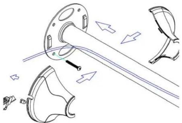
73 - 123cm 31 - 41cmEach pole has its own cable management system. Using a conduit up the centre of the pole you can hide unsightly power and video cables from view.
The diagram below shows how the cable is fed through the pole and can either go up through the ceiling or out through the side of the cable cover for a tidier appearance.
natural_image
Technical line drawing of mechanical components with arrows indicating motion or assembly (no text or symbols)Assembling the "box" bracket: 40848
The "box" bracket comes with the following pieces:

text_image
B. 1/4" x10pcs C. M6x10pcs D. 4pcs E. 1pc F. 1pc G. 4pcs H. 1pc I. 1pc
text_image
Technical diagram of a mechanical assembly with labeled components A through HStep 2
Attach the foam strip (G) as shown, to bottom bracket (E). Using nuts (C) and washers (B), attach the first part of the bottom bracket (E) to the L piece (D).
Step 1
Attach 2 foam strips (G) to the underside of the main bracket as shown. This will protect your projector from scratching against the metal surfaces. Connect the 4 L pieces (D) to each corner of the main bracket using nuts (C), washers (B) and tighten with spanner (H).
text_image
Technical diagram of a mechanical assembly with labeled parts G and F, showing structural components and directional arrows.
text_image
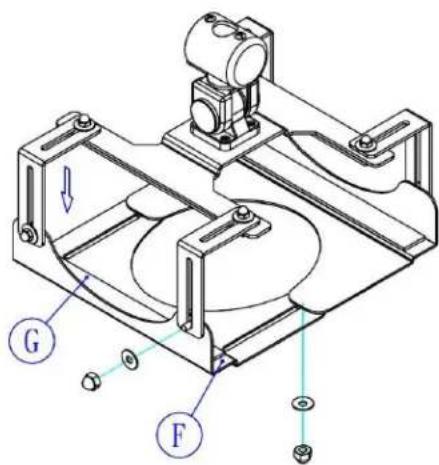
Technical diagram of a mechanical assembly with labeled parts E and GStep 3
Attach the last foam strip (G) to the second bottom bracket (F). Then attach (F) to the L pieces (D) using the nuts (C) and washers (B). The remaining nuts and washers are to connect the two bottom brackets (E) as shown.
Note: you will need to adjust the size of the "box" bracket by loosening and tightening nuts (C) depending on the size of your projector.
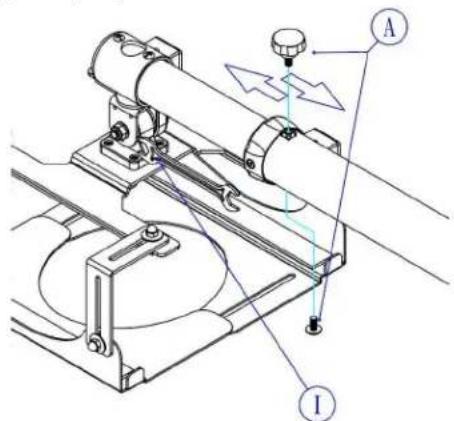
Step 4
After attaching the main bracket to the pole you can adjust the length of the pole and lock it with screws (A). Adjusting the bolt with the spanner (I) will allow you to tilt and adjust your projector to fit your requirements.
text_image
Technical diagram of a mechanical device with labeled components A and I, showing motion indicators and structural features.Assembling the "X" bracket: 40849
The "X" bracket comes with the following pieces:

text_image
M6×10 B. 4pcs M4×16 M5×16 M6×16 C. 4pcs/each M5 D. 4pcs E. 4pcs F. 1pc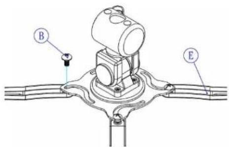
text_image
B EStep 1
Attach the four expansion posts (E) to the main bracket, using screws (B).
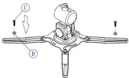
Step 2
Use bolts (C) as appropriate to your projector and washers (D) to attach your projector to the "X" bracket.
text_image
Technical diagram of a mechanical component with labeled parts C and D, showing assembly or assembly details.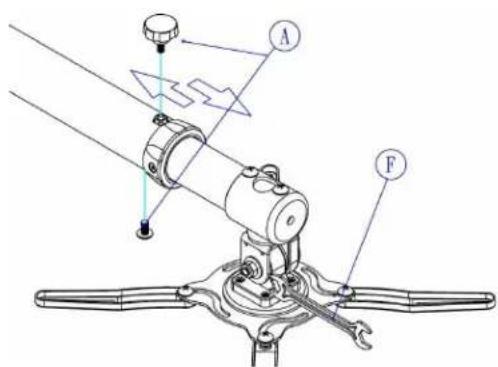
text_image
Technical diagram of a mechanical device with labeled parts A and F, showing motion indicators and components.Step 3
After attaching the main bracket to the pole you can adjust the length of the pole and lock it with screws (A). Adjusting the bolt with the spanner (F) will allow you to tilt and adjust your projector to fit your requirements.
Note: you will need to adjust the size of the "X" bracket by loosening and tightening nuts (C) and (B) depending on the size of your projector.
LINDY No's 40846, 40847, 40848 & 40849
1 ^st Edition November 2010
www.lindy.com