PU-DVI1109RX - Émetteur/récepteur AV CYP - Free user manual and instructions
Find the device manual for free PU-DVI1109RX CYP in PDF.

User questions about PU-DVI1109RX CYP
0 question about this device. Answer the ones you know or ask your own.
Ask a new question about this device
Download the instructions for your Émetteur/récepteur AV in PDF format for free! Find your manual PU-DVI1109RX - CYP and take your electronic device back in hand. On this page are published all the documents necessary for the use of your device. PU-DVI1109RX by CYP.
USER MANUAL PU-DVI1109RX CYP
text_image
PVIH CASSIS/7 with LAN/RS232 CATSe/6/7 to DVI with LAN/IR:RS232 Receiver Power IR 1 Extender IR 2 Bleaver RS232 Out Link CATSe/6/7 InCHDBT ^®
PU-DVI1109TX & RX
DVI 5-Play HDBaseT™ Transmitter and Receiver inc. PoC & 2x LAN, up to 100m
OPERATION MANUAL
DISCLAIMERS
The information in this manual has been carefully checked and is believed to be accurate. CYP (UK) Ltd assumes no responsibility for any infringements of patents or other rights of third parties which may result from its use.
CYP (UK) Ltd assumes no responsibility for any inaccuracies that may be contained in this document. CYP (UK) Ltd also makes no commitment to update or to keep current the information contained in this document.
CYP (UK) Ltd reserves the right to make improvements to this document and/or product at any time and without notice.
COPYRIGHT NOTICE
No part of this document may be reproduced, transmitted, transcribed, stored in a retrieval system, or any of its part translated into any language or computer file, in any form or by any means—electronic, mechanical, magnetic, optical, chemical, manual, or otherwise—without express written permission and consent from CYP (UK) Ltd.
© Copyright 2011 by CYP (UK) Ltd.
All Rights Reserved.
Version 1.1 August 2011
TRADEMARK ACKNOWLEDGMENTS
All products or service names mentioned in this document may be trademarks of the companies with which they are associated.
SAFETY PRECAUTIONS
Please read all instructions before attempting to unpack, install or operate this equipment and before connecting the power supply.
Please keep the following in mind as you unpack and install this equipment:
- Always follow basic safety precautions to reduce the risk of fire, electrical shock and injury to persons.
- To prevent fire or shock hazard, do not expose the unit to rain, moisture or install this product near water.
- Never spill liquid of any kind on or into this product.
- Never push an object of any kind into this product through any openings or empty slots in the unit, as you may damage parts inside the unit.
- Do not attach the power supply cabling to building surfaces.
- Use only the supplied power supply unit (PSU). Do not use the PSU if it is damaged.
- Do not allow anything to rest on the power cabling or allow any weight to be placed upon it or any person walk on it.
- To protect the unit from overheating, do not block any vents or openings in the unit housing that provide ventilation and allow for sufficient space for air to circulate around the unit.
REVISION HISTORY
VERSION NO. DATE SUMMARY OF CHANGE
| v1.00 06/06/2017 First release | ||
CONTENTS
- Introduction......6
- Applications ......6
- Package Contents ......6
- System Requirements ....7
- Features......7
- Operation Controls and Functions .....8
6.1 Transmitter Front and Rear Panels......8
6.2 Receiver Front and Rear Panels ...... 9
6.3 IR Cable Pin Assignment .....10
6.4 D-Sub 9-Pin Definitions....10 - Connection Diagram ......11
- Specifications....12
- Acronyms....13
1. INTRODUCTION
This HDBaseT DVI over CAT5e/6/7 Transmitter and Receiver set can transmit DVI video, analog audio, 2 LAN serving connections, control (RS-232 and IR) and Power over Cable (PoC) over a single CAT5e/6/7 cable up to 100m. The Transmitter can power the Receiver, via the PoC function, eliminating the need for a separate power supply providing greater flexibility in installations.
2. APPLICATIONS
Household entertainment media sharing and control
Lecture room display and control
Showroom display and control
■ Meeting room presentation and control
Classroom display and control
■ Any Smart AV Installation system
3. PACKAGE CONTENTS
Transmitter Package
DVI to CAT5e/6/7 with LAN/PoC/IR Transmitter
1×IR Blaster
1×IR Receiver
24 V DC Power Adaptor
Operation Manual
Receiver Package
CAT5e/6/7 to DVI with LAN/PoC/IR Receiver
1×IR Blaster
1×IR Receiver
Operation Manual
Note: Units are sold separately
4. SYSTEM REQUIREMENTS
Input DVI source equipment such as PC/Laptop and output display with DVI input.
RS232 controlled device
Ethernet equipped device
5. FEATURES
Simultaneous transmission of uncompressed video and audio (1080p@60Hz/-Deep Color) over a single CAT5e/6/7 cable for up to 100 m (300 ft.).
Supports High-definition Audio up to LPCM 7.1CH, Dolby TrueHD and DTS-HD Master Audio with HDMI to DVI adaptor
Connect and share up to 4 LAN connections (2 at the Transmitter end, 2 at the Receiver end) at speeds up to 100 Mbps
Supports Bi-directional IR control and RS-232 pass-through
Supports 5Play™ convergence: HD video, audio & Control ports (IR and RS232)/LAN/PoC
Installation friendly
Single power supply powers both units, Receiver unit is powered through the Transmitter via PoC
Note:
- This system was tested with CAT6/23AWG cables, results may vary with cables of a different specification.
- The PoC function is designed for powering compatible Receiver units only—non-PoC Receivers will need their own power supply. Receivers of another brand may not be compatible.
- Supporting 4K2K resolution with DVI to HDMI adaptor cable.
6. OPERATION CONTROLS AND FUNCTIONS
6.1 Transmitter Front and Rear Panels
Front

text_image
POWER DC 24V IR 1 OUT IR 2 IN RS232 IN LINK CAT5e/6/7 OUT 12 456 10Rear
text_image
AUDIO IN LAN 2LAN 1RLDVI IN1 Power LED: This LED will illuminate when the 24V DC Adaptor is connected to the AC outlet.
2 DC 24V: Plug the 24V DC power supply into the unit and connect the adaptor to an AC outlet.
3 IR 1 OUT: Connect to the supplied IR Blaster cables for IR signal transmission. Place the IR Blaster in direct line-of-sight of the equipment to be controlled. The related IR Receiver port is IR1 IN.
4 IR 2 IN : Connect to the supplied IR Receiver cables for IR signal reception. Ensure that remote being used is within the direct line-of-sight of the IR Extender. The related IR Transmitter port is IR2 OUT.
5 RS-232 IN: Connect to a PC/Laptop with a D-Sub 9-pin male cable for the transmission of RS-232 commands.
6 Link LED: The yellow LED will illuminate when both the input source and output display signals are connected through the CAT cable. When it blinks regularly it states the source is NOT sending a signal to the Transmitter but the Transmitter and Receiver are linked and if it blink irregularly it states an error has occurred.
7 CAT5e/6/7 OUT: Connect the Transmitter and Receiver via a single CAT5e/6 type cable for all data transmission.
8 DVI IN: Connect to the DVI equipped source equipment such as PC or Laptop.
9 AUDIO IN L/R: Connect from audio source equipment for audio signal output to L/R output on the Receiver side.
10 LAN 1/2: The LAN connections can be used to connect and share up to 4 Ethernet connections (2 at the Receiver end, 2 at the Transmitter end), including computers, routers and media servers.
6.2 Receiver Front and Rear Panels
Front

text_image
POWER IR 1 IN IR 2 OUT RS232 OUT LINK CAT5e/6/7 IN 12Rear

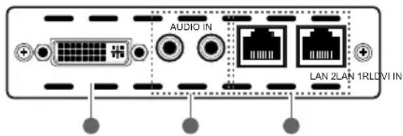
text_image
AUDIO OUT LAN 2LAN 1RLDVI OUT1 Power LED: The LED will illuminate when the 24 V DC Adaptor is connected to the AC outlet.
2 IR 1 IN: Connect to supplied the IR Receiver cables for IR signal reception. Place the IR Blaster in direct line-of-sight of the equipment to be controlled. The related IR Transmitter port is IR1 OUT.
3 IR 2 OUT: Connect to the supplied IR Blaster cables for IR signal transmission. Ensure that remote being used is within the direct line-of-sight of the IR Extender. The related IR Receiver port is IR2 IN.
4 RS-232 OUT: Connect to a RS-232 enabled device with a D-Sub 9-pin female cable for the transmission of RS-232 commands.
5 Link LED: The yellow LED will illuminate when both the input source and output display signals are connected through the CAT cable. When it blinks regularly it states the source is NOT sending a signal to the Transmitter but the Transmitter and Receiver are linked and if it blink irregularly it states an error has occurred.
6 CAT5e/6/7 IN: Connect the Transmitter and Receiver via a single CAT5e/6 type cable for all data transmission.
7 DVI OUT: Connect to a DVI equipped display or monitor to display the DVI input source signal.
8 AUDIO OUT L/R: Connect to active speakers or amplifier for audio signal output.
9 LAN 1/2: The LAN connections can be used to connect and share up to 4 Ethernet connections (2 at the Receiver end, 2 at the Transmitter end), including computers, routers and media servers.
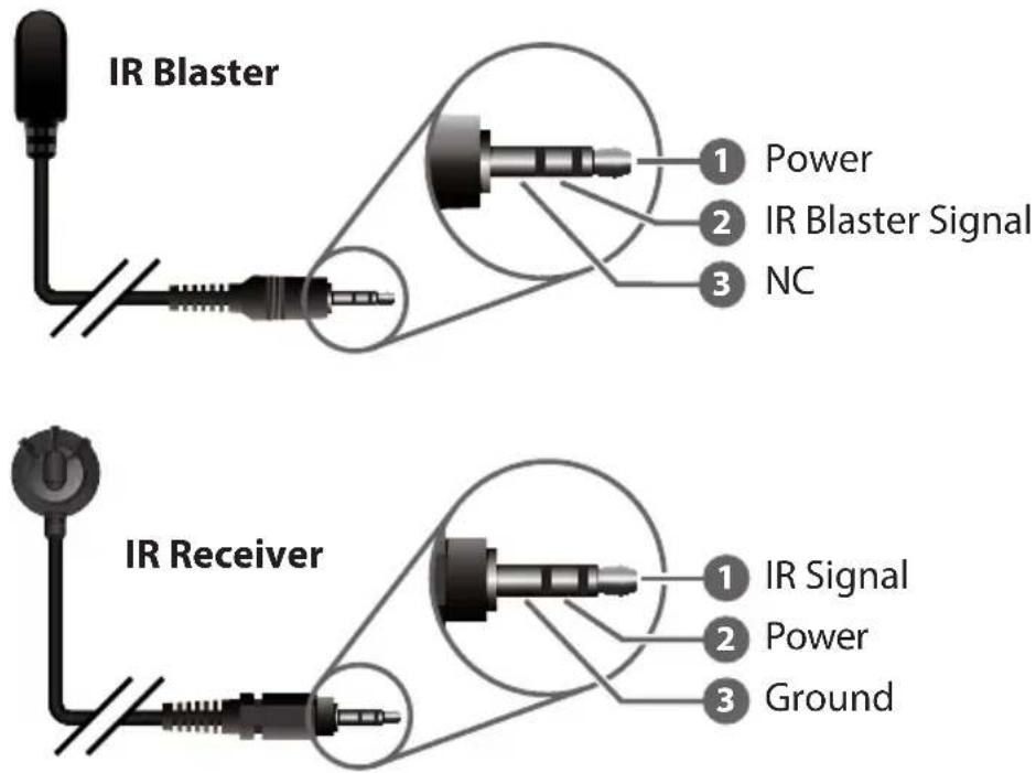
6.3 IR Cable Pin Assignment
text_image
IR Blaster 1 Power 2 IR Blaster Signal 3 NC IR Receiver 1 IR Signal 2 Power 3 Ground6.4 D-Sub 9-Pin Definitions
| Pin Define TX/RX | |
| 1 N/C | |
| 2 TxD / RxD | |
| 3 RxD / TxD | |
| 4 N/C | |
| 5 GND | |
| 6 N/C | |
| 7 N/C | |
| 8 N/C | |
| 9 N/C | |
- CONNECTION DIAGRAM

flowchart
graph TD
    A["PC with RS232 Control"] -->|1.5m 60°| B["IR Blaster"]
    B --> C["IR Extender"]
    C --> D["Modem/Router"]
    D --> E["Media Server"]
    F["Power Supply"] --> G["RS232 Controlled Device"]
    G --> H["IR Extender"]
    H --> I["IR Blaster"]
    I --> J["Single CAT5e/6/7"]
    K["Monitor/Display"] --> L["IR BLASTER"]
    M["Active Speakers"] --> N["Notebook"]
    O["PC"] --> P["Monitor/Display"]
    Q["IR Receiver"] --> R["Monitor/Display"]
    S["Video Player"] --> T["Monitor/Display"]
8. SPECIFICATIONS
Video Bandwidth 340 MHz/10.2 Gbps
Ethernet Speed 100 Mbps
Transmitter
Inputs 1×DVI, 2×Ethernet, 1 × L/R
1×RS-232, 1×IR Extender
Outputs 1×CAT5e/6/7, 1×IR Blaster
Receiver
Inputs 1×CAT5e/6/7, 1×IR Extender
Outputs 1×DVI, 1×RS-232, 1 × L/R
2 × Ethernet, 1×IR Blaster
DVI In/Out Cable Distance Up to 6 Meters
CAT6 In/Out Cable Up to 100 Meters
Distance
DVI In/Out Supports 480i\~1080p@50/60, 1080p@24,
Resolution VGA\~WUXGA(Dual Link DVI Not Supported)
IR Frequency 30\~50 kHz
ESD Protection Human body model:
±8kV (air-gap discharge)
±4kV (contact discharge)
Power Supply 24 V/1.25 A DC (US/EU Standards, CE/FCC/UL certi-
fied)
Dimensions 125 mm(W) x 123 mm (D) x 30 mm (H)/Jacks
Excluded
125 mm(W) x 135 mm (D) x 30 mm (H)/Jacks
Included
Weight 384 g (TXC)
392 g (RXC)
Chassis Material Aluminum
Silkscreen Color Black
Operating Temperature 0°C\~40°C/32°F\~104°F
Storage Temperature -20^ 60^ / -4^ 140^
Relative Humidity 20\~90 % RH (non-condensing)
Power Consumption 13 W
9. ACRONYMS
| ACRONYM COMPLETE TERM | |
| CAT5e Category 5 Cable | |
| CAT6 Category 6 Cable | |
| CAT7 Category 7 Cable | |
| HDMI High Definition | Multimedia Interface |
| PoC Power over Cable | |

CYP (UK) Ltd., Unit 7, Shepperton Business Park, Govett Avenue, Shepperton, Middlesex, TW17 8BA
Tel: +44 (0) 20 3137 9180 | Fax: +44 (0) 20 3137 6279
Email: sales@cypeurope.com
www.cypeurope.com
v1.00