REALiS SX7 Mark II D - Video projector CANON - Free user manual and instructions
Find the device manual for free REALiS SX7 Mark II D CANON in PDF.

User questions about REALiS SX7 Mark II D CANON
0 question about this device. Answer the ones you know or ask your own.
Ask a new question about this device
Download the instructions for your Video projector in PDF format for free! Find your manual REALiS SX7 Mark II D - CANON and take your electronic device back in hand. On this page are published all the documents necessary for the use of your device. REALiS SX7 Mark II D by CANON.
USER MANUAL REALiS SX7 Mark II D CANON
natural_image
Black Canon projector with visible lens and ventilation grille (no text or symbols on body)Table of contents/Safety Instructions
Before Use
Setting Up the Projector
Projecting an Image from the Computer
Projecting an Image from AV Equipment
Useful Functions Available During a Presentation
Setting Up Functions from Menus
Maintenance
Troubleshooting
Appendix
Index
Quick Reference – How to start projection

Computer
1. Install the projector. P32-33
- Install the projector at the desired distance from the screen.
2. Connect the projector. P36-39
- Connect the projector and the computer with a cable.
3. Turn on the projector. P40-41
- Connect the power cord and turn on the projector.
- Adjust the height of the projecting image (P43).
- Select a display language when turning on the projector for the first time (P41).
4. Press the button twice. P46-47
- Adjust the focus of the screen.
5. Set up the computer. P44-45
- Turn on the computer and set the resolution.
6. Select the input signal by pressing the INPUT button. P48-50
- Select an appropriate input signal in accord with the signal from the computer.
7. Press the button twice again. P46-47
- Adjust the input signal, focusing, keystone distortion, etc. automatically with the auto setup function.
8. Press the button.
- Optimize the input signal with the auto PC function (Skip this step if the projector is projecting an image properly.)
9. Select the image mode with the button.
- Select an appropriate image mode for projection.
- Specify the aspect ratio or display area in the [Aspect] menu as required (P57, 90).
10. Start the presentation.
- Set the useful functions available during the presentation from the remote control.
Finishing the projection...
Turn off the projector
● Turn off the projector and unplug the power cord.
P54
P55-56
P78-83
P60-61

AV Equipment
1. Install the projector. P32-33
● Install the projector at the desired distance from the screen.
● Install batteries in the remote control (P29)
2. Connect the projector. P64-68
- Connect the projector and the AV equipment with a cable* (see P38, 39 for the instruction on connecting a audio cable).
3. Turn on the projector. P40-41
- Connect the power cord and turn on the projector.
- Adjust the height of the projecting image (P43).
- Select a display language when turning on the projector for the first time (P41).
4. Press the button twice. P46-47
- Adjust the focus of the screen.
5. Set up the AV equipment.
- Turn on the AV equipment and play the video image.
6. Select the input signal by pressing the INPUT button. P70-72
- Select DIGITAL VIDEO as the input signal for a digital video image.* For the other video image, go to step 7.
7. Press the button twice again. P70
- Adjust the input signal, focusing, keystone distortion, etc. automatically with the auto setup function.
8. Select the image mode with the IMAGE button. P55-56
- Select an appropriate image mode for projection.
- Specify the aspect ratio or display area in the [Aspect] menu as required (P73, 90, 91).
Finishing the projection...
Turn off the projector
P60-61
- Turn off the projector and unplug the power cord.
* Connect the projector and the AV equipment with a HDMI/DVI cable to project a digital video image (P65).
Table of Contents
Quick Reference – How to start projection.... 2
Table of Contents 4
Safety Instructions....7
Safety Precautions....8
AC Power Cord Requirement....11
Federal Communication Commission Notice 12
Canadian Radio Interference Regulations 12
Precautions on Handling the Batteries in the Remote Controller 13
Lamp Handling Precautions 13
Carrying/Transporting the Projector 14
Installation Precautions 14
Features of the Multimedia Projector SX7 MarkII/SX60.... 16
Supplied Manuals and Symbols Used in This Manual 17
Supplied Manuals....17
Before Use 20
Supplied Accessories 20
Part Names....22
Preparing the Remote Control....29
Setting Up the Projector 32
Determining the Distance to the Screen 32
Determining the Installation Position 33
Projecting an Image from the Computer 36
Connecting the Projector to the Computer....36
Starting Projection 40
Adjusting the Image 42
Preparing the Computer 44
Performing the Auto Setup 46
Adjusting the Focus....51
Adjusting Keystone Distortion 52
Setting Up the Computer Screen Automatically (AUTO PC)....54
Selecting an Image Mode (IMAGE) 55
Selecting a Screen Mode (Aspect) 57
Selecting Aspect Ratio of the Projecting Image (Screen aspect)....59
Turning Off the Projector 60
Projecting an Image from AV Equipment 64
Connecting the Projector to an AV Equipment....64
Projecting a Video Image from an AV Equipment.... 69
Performing the Auto Setup 70
Selecting a Screen Mode (Aspect) 73
Selecting Aspect Ratio of the Projecting Image (Screen aspect)....74
Useful Functions Available During a Presentation 78
Blackened Out an Image Temporarily 78
Freezing the Picture 78
Muting the Sound 79
Adjusting the Volume 79
Showing the Elapsed Time....80
Page Up or Down through the Pages 80
Zooming an Image 81
Operating a Mouse with the Remote Control 82
Pointing with a Spotlight 83
Setting Up Functions from Menus 86
How to Use Menus 86
Setting Display Status 90
Selecting a Screen Mode (1)....90
Selecting a Screen Mode (2)....90
Selecting a Screen Mode (3)....91
Selecting an Input Signal Type (1)....91
Selecting an Input Signal Type (2) 92
Selecting an Input Signal Type (3) 92
Adjusting the Total Number of Dots 93
Adjusting the Tracking 93
Adjusting the Horizontal Position....94
Adjusting the Vertical Position....94
Adjusting the Number of Horizontal Pixels....95
Adjusting the Number of Vertical Pixels 95
Performing Progressive Processing 96
Selecting a Menu Position 96
Performing the Ceiling-mounted/Rear Projection.... 97
Correcting the Screen Color....98
Capturing a Logo to Be Projected (SX60)....98
Selecting a Logo Display Position (SX60) 99
Displaying a Logo (No signal screen)....99
Displaying a Logo (NO SHOW).... 100
Selecting a Logo at Startup....100
Selecting Aspect Ratio of the Screen.... 101
Setting the Image Quality 102
Selecting an Image Mode 102
Adjusting the Brightness 103
Adjusting the Contrast....103
Adjusting the Sharpness .... 104
Making a Gamma Correction 104
Making Color Adjustment (1) (SX7 II)....105
Making Color Adjustment (2)....105
Making Color Adjustment (3)....106
Making Advanced Color Adjustment (1)....106
Making Advanced Color Adjustment (2) 107
Making Advanced Color Adjustment (3) 107
Correcting the Image According to the Ambient Light (SX7 II) 108
Reducing the Lamp Brightness.... 109
Resetting the Image Settings 110
Setting Various Function 111
Setting Auto Setup Function....111
Selecting the Power Management Mode 111
Skip the POWER Button Operation 112
Enabling/Disabling the Beep.... 112
Selecting a Display Language 113
Prohibiting the Projector Operation 114
Enabling/Disabling the Guide Message.... 114
Turning On/Off the LED Illumination.... 115
Setting up the Remote Control 115
Setting up the Digital Video Input Signal 116
Setting a Password....116
Registering a Password 117
Resetting to the Default Setting....117
Resetting the Lamp Counter 118
Maintenance.... 120
Cleaning the Projector....120
Cleaning and Replacing the Air Filter 121
Replacing the Lamp 122
Troubleshooting.... 126
WARNING Lamp Flash Patterns.... 126
Symptoms and Solutions.... 127
Appendix 132
Supported Computer Signal Types.... 132
Relationship between Screen Size and Projecting Distance 133
Glossary 134
Specifications....138
Index 140
Menu Configuration 144
Safety Instructions
Before operating this projector, read this manual thoroughly in order to operate the projector properly.
This projector offers many convenient features and functions. Operating the projector properly enables you to manage those features and maintain it in good condition for a long period.
Improper operation may result in not only reducing the product-life, but also malfunctions, fire hazards, or other accidents.
If your projector is not operating correctly, read this manual again, check operations and cable connections, and try the solutions shown in the "Troubleshooting" section at the end of this booklet. If the problem still persists, contact the service center or the dealer where you purchased the projector.

CAUTION
RISK OF ELECTRIC SHOCK DO NOT OPEN

CAUTION: TO REDUCE THE RISK OF ELECTRIC SHOCK, DO NOT REMOVE COVER (OR BACK). THERE ARE NO USER-SERVICEABLE PARTS INSIDE EXCEPT LAMPS. REFER SERVICING TO QUALIFIED SERVICE PERSONNEL.
THIS SYMBOL INDICATES THAT DANGEROUS VOLTAGE CONSTITUTING A RISK OF ELECTRIC SHOCK IS PRESENT WITHIN THIS UNIT.

THIS SYMBOL INDICATES THAT THERE ARE IMPORTANT OPERATING AND MAINTENANCE INSTRUCTIONS FOR THIS UNIT IN THE OWNER'S MANUAL.
CAUTION
Not for use in a computer room as defined in the Standard for the Protection of Electronic Computer/Data Processing Equipment, ANSI/NFPA 75.

Safety Precautions
WARNING: TO REDUCE THE RISK OF FIRE OR ELECTRIC SHOCK, DO NOT EXPOSE THIS APPLIANCE TO RAIN OR MOISTURE.
- This projector projects intense light from the projection lens. Do not stare directly into the lens if possible, as doing so may result in eye damage. Be especially careful that children do not stare directly into the beam.
- Install the projector in an appropriate position. Installing the projector in an inappropriate position may result in a fire hazard.
- Allow for appropriate space above beside and behind of the projector cabinet for allowing air circulation and cooling of the projector. Minimum clearances must be maintained. If the projector is to be built into a compartment or similarly space, the minimum distances must be maintained. Do not cover the ventilation slot on the projector. Heat build-up can reduce the service life of your projector, and can also be dangerous.
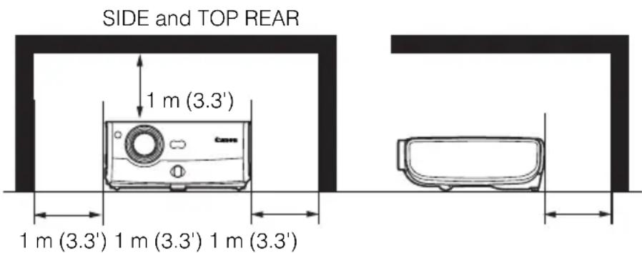
text_image
SIDE and TOP REAR 1 m (3.3') 1 m (3.3') 1 m (3.3') 1 m (3.3')- Do not put any flammable objects or spray cans near the projector, as the hot air exhausted from the ventilation holes may result in an explosion.
- If the projector is not to be used for an extended period of time, unplug it from the power outlet.
READ AND KEEP THIS OWNER'S MANUAL FOR LATER USE.
All the safety and operating instructions should be read before beginning to operate the product.
Read all of the instructions given here and retain them for later use. Unplug this projector from the AC power supply before cleaning. Do not use liquid or aerosol cleaners on the projector. Use a damp cloth for cleaning.
Follow all warnings and instructions marked on the projector.
For added protection of the projector during a lightning storm, or when it is left unattended or unused for long periods of time, unplug it from the wall outlet. This will prevent damage due to lightning and power surges.
Do not expose this unit to rain or use near water... for example, in a wet basement, near a swimming pool, etc...
Do not use attachments not recommended by the manufacturer as they may result in hazards.
Do not place this projector on an unstable cart, stand, or table. The projector may fall, causing serious injury to a child or adult, and serious damage to the projector. Use only with a cart or stand recommended by the manufacturer, or sold with the projector. Wall or shelf mounting should be carried out in accordance with the manufacturer's directions, and should use a mounting kit approved by the manufacturers.
An appliance and cart combination should be moved with care.
Sudden stops, excessive force, and uneven surfaces may cause the appliance and cart combination to overturn.
Slots and openings in the back and bottom of the cabinet are provided for ventilation, to insure reliable operation of the equipment and to protect it from overheating.

natural_image
Symbolic illustration of a person climbing a ladder with a monitor, enclosed in a large circle (no text or symbols)The openings should never be covered with cloth or other materials, and the bottom opening should not be blocked by placing the projector on a bed, sofa, rug, or other similar surface. This projector should never be placed near or over a radiator or heat register.
This projector should not be placed in a built-in installation such as a book case unless proper ventilation is provided.
Never push objects of any kind into this projector through cabinet slots as they may touch dangerous voltage points or short out parts that could result in a fire or electric shock. Never spill liquid of any kind onto the projector.
Do not install the projector near the ventilation duct of air-conditioning equipment.
This projector should be operated using only the type of power source indicated on the marking label. If you are not sure of the type of power supplied, consult your authorized dealer or local power company.
Do not overload wall outlets and extension cords as this can result in fire or electric shock. Do not allow anything to rest on the power cord. Do not locate this projector where the cord may be damaged by people walking on it.
Do not attempt to service this projector yourself as opening or removing covers may expose you to dangerous voltages or other hazards. Refer all servicing to qualified service personnel.
Unplug this projector from the wall outlet and refer servicing to qualified service personnel under the following conditions:
a. When the power cord or plug is damaged or frayed.
b. If liquid has been spilled into the projector.
c. If the projector has been exposed to rain or water.
d. If the projector does not operate normally after following the operating instructions. Adjust only those controls that are covered in the operating instructions as improper adjustment of other controls may result in damage and will often require extensive work by a qualified technician to restore the projector to normal operating condition.
e. If the projector has been dropped or the cabinet has been damaged.
f. When the projector exhibits a distinct change in performance-this indicates a need for servicing.
When replacement parts are required, be sure the service technician uses replacement parts specified by the manufacturer that have the same characteristics as the original parts. Unauthorized substitutions may result in fire, electric shock, or injury.
Upon completion of any service or repairs to this projector, ask the service technician to perform routine safety checks to determine that the projector is in safe operating condition.
AC Power Cord Requirement
The AC Power Cord supplied with this projector meets the requirements for use in the country you purchased it.
AC Power Cord for the United States and Canada:
The AC Power Cord used in the United States and Canada is listed by the Underwriters Laboratories (UL) and certified by the Canadian Standard Association (CSA).
The AC Power Cord has a grounding-type AC line plug. This is a safety feature to ensure the plug fits into the power outlet. Do not try to tamper with this safety feature. Should you be unable to insert the plug into the outlet, contact your electrician.
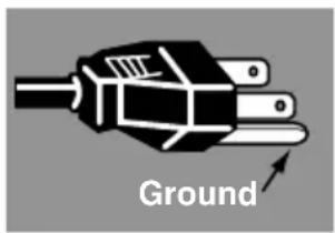
text_image
GroundTHE SOCKET-OUTLET SHOULD BE INSTALLED NEAR THE EQUIPMENT AND EASILY ACCESSIBLE.
NOTE FOR CUSTOMERS IN THE US
Hg LAMP(S) INSIDE THIS PRODUCT CONTAIN MERCURY AND MUST BE RECYCLED OR DISPOSED OF ACCORDING TO LOCAL, STATE OR FEDERAL LAWS.

natural_image
Symbol of a trash bin crossed out by two diagonal lines (no text or numbers present)

natural_image
Symbol of a trash bin crossed out by two diagonal lines (no text or labels)European Union (and EEA) only.
These symbols indicate that this product is not to be disposed of with your household waste, according to the WEEE Directive (2002/96/EC), the Battery Directive (2006/66/EC) and/or your national laws implementing those Directives. If a chemical symbol is printed beneath the symbol shown above, in accordance with the Battery Directive, this indicates that a heavy metal (Hg = Mercury, Cd = Cadmium, Pb = Lead) is present in this battery or accumulator at a concentration above an applicable threshold specified in the Battery Directive. This product should be handed over to a designated collection point, e.g., on an authorized one-for-one basis when you buy a new similar product or to an authorized collection site for recycling waste electrical and electronic equipment (EEE) and batteries and accumulators. Improper handling of this type of waste could have a possible impact on the environment and human health due to potentially hazardous substances that are generally associated with EEE. Your cooperation in the correct disposal of this product will contribute to the effective usage of natural resources. For more information about the recycling of this product, please contact your local city office, waste authority, approved scheme or your household waste disposal service or visit
www.canon-europe.com/environment.
(EEA: Norway, Iceland and Liechtenstein)
Federal Communication Commission Notice
Multimedia Projector, Model: SX7 MarkII/SX60
This device complies with Part 15 of the FCC Rules. Operation is subject to the following two conditions:
(1) This device may not cause harmful interference, and
(2) this device must accept any interference received, including interference that may cause undesired operation.
Note: This equipment has been tested and found to comply with the limits for a Class B digital device, pursuant to Part 15 of the FCC Rules. These limits are designed to provide reasonable protection against harmful interference in a residential installation. This equipment generates, uses and can radiate radio frequency energy and, if not installed and used in accordance with the instructions, may cause harmful interference to radio communications. However, there is no guarantee that interference will not occur in a particular installation. If this equipment does cause harmful interference to radio or television reception, which can be determined by turning the equipment off and on, the user is encouraged to try to correct the interference by one or more of the following measures:
● Reorient or relocate the receiving antenna.
- Increase the separation between the equipment and receiver.
- Connect the equipment into an outlet on a circuit different from that to which the receiver is connected.
- Consult the dealer or an experienced radio/TV technician for help.
The cable with a ferrite core provided with the projector must be used with this equipment in order to comply with Class B limits in Subpart B of Part 15 of the FCC rules. Use of a shielded cable is required to comply with class B limits in Subpart B of Part 15 of FCC Rules.
Do not make any changes or modifications to the equipment unless otherwise specified in the instructions. If such changes or modifications should be made, you could be required to stop operation of the equipment.
Canon U.S.A. Inc.
One Canon Plaza, Lake Success, NY 11042-1198, U.S.A.
Tel No. (516) 328-5600
Canadian Radio Interference Regulations
This Class B digital apparatus complies with Canadian ICES-003.
Precautions on Handling the Batteries in the Remote Controller
 Caution Caution | Observe the following precautions when handling the batteries. Failure to do so may cause explosion, heat generation, fire, or leakage of the battery fluid.Do not heat or disassemble the batteries, or throw them into fire.Do not attempt to recharge the batteries. |
 Waming Waming | Observe the following precautions when handling the batteries. Failure to do so may cause explosion, heat generation, fire or leakage of the battery fluid.Remove the batteries when they have been exhausted or not in use for an extended period of time.Be sure to replace both batteries at the same time. Do not mix batteries of different types.Insert batteries correctly according to the "+" and "-" markings.If a fluid from a battery leaks and comes in contact with your skin, rinse the affected skin thoroughly as soon as possible. |
Lamp Handling Precautions
This projector uses a high-pressure mercury lamp which must be handled carefully and correctly as mentioned below.
The mercury lamp has the following characteristics.
- A lamp may explode with a loud sound or burn out due to a shock, scratch, or use beyond its expiry date.
- The lamp life may differ from lamp to lamp and according to the usage environment. There is no guarantee that all lamps will last for the same period of time. Some lamps may fail in a shorter period of time than other similar lamps.
● A lamp gradually becomes darker over time.

Warning
If a Lamp Explodes
- If a lamp explodes, gas or dust may come out of the exhaust vent. Open windows and doors for ventilation.
- The gas contains toxic mercury. Always keep your face away from the exhaust vent when the projector is operating to avoid inhaling mercury vapors or to prevent it from getting in your eyes or mouth.
- If you inhale the gas or the shards of the broken lamp contact your eyes or mouth, consult a doctor immediately.
- If a lamp explodes, its shards may scatter inside the projector. Ask the Canon service representative to clean and check the inside of the projector and replace the lamp.

Caution
If the projector indicates that the lamp should be replaced (i.e., the LAMP REPLACE indicator lights up twice),
- The chances of an explosion increase. Replace the lamp with a new one immediately if such is the case.

Disposal of Waste Lamp
- Dispose of the projector's mercury lamp according to local regulations just like the fluorescent lamps.
Carrying/Transporting the Projector

- This projector is a precision machine. Do not subject the projector to strong shocks or vibrations or turn it down.
- Install the lens cap to protect the lens and put the projector in the carrying bag to protect it from dust and scratches on the surface of it when you carry the projector. For details, see P21.
- Wait until the cooling fan stops before putting the projector in the carrying bag. Do not put the projector in the carrying bag until the cooling fan stops rotating. The projector may be damaged due to the heat.
- Replace the adjustable foot before putting the projector in the carrying bag. The projector may be damaged if you put it in the bag without replacing the adjustable foot.
- The carrying bag is not designed to protect the projector from external shocks. When carrying the projector with it put in the carrying bag, do not give a shock to it, drop it, or place anything on it. The projector may be damaged or malfunctioned.
- Do not transport the projector through a courier or transport service with the carrying bag. Put the projector in an impact-resistant transport case if such is the case.
Installation Precautions

The area around the exhaust vent and the cabinet above the exhaust vent become hot when the projector is operating.
- Do not touch these areas, or you may get burnt. In particular, keep children away from these areas. Do not put anything that may deform or discolor due to heat on the projector.
Hot air is exhausted from the exhaust vent. Observe the following:
- Do not put any metallic object on the projector. It may become hot, resulting in accident or injury.
- Do not seat anyone near the exhaust vent. Otherwise, you may get burned.

text_image
CARS Hot air
When placing the projector on a castered stand or table, be sure to lock the casters.
- Failure to do so may cause the projector to move or topple, resulting in an injury.
Position the projector in a horizontal position. Incorrect installation may cause troubles and accidents.
- Do not tilt the projector more than 20 degrees above and below the horizontal.
- When you want to use your projector pointing up or down, make sure to place the projector straight up or down.

text_image
20° 20°Do Not Use in the Following Environments
- Do not place the projector on an unstable or slanted surface. The projector may fall causing a personal injury.
- Do not place it in an oily, smoky, or damp location (e.g., near a cooking table or a humidifier). It may cause a fire or an electric shock.
- Place the projector with a minimum distance of 1 m (3.3') from its left, right, rear, and top panels to the neighboring object such as a wall. Otherwise, it may damage the projector due to bad exhaust ventilation.
- Do not put anything near the exhaust vent that may deform or deteriorate due to heat.
- Do not install the projector in a humid or dusty location or a position where there is a lot of oily or cigarette smoke. Optical parts such as a lens and mirror may be stained, resulting in poor picture quality.
- Do not place it near an exhaust outlet of air-conditioning equipment. Otherwise, it may be damaged.
If the projector is carried from a cold place to a warm place or the room temperature is raised rapidly, condensation may form on the lens and mirror due to the moisture in the atmosphere, resulting in a blurred picture. Wait until condensation evaporates and normal picture is shown.
Do not use the projector in a place subject to either very high or very low temperatures. Doing so may cause malfunction. The ranges of the operating and storage temperatures are as shown below:
Operating temperature: +5°C to +35°C (Humidity: 85% or below)
Storage temperature: -10°C to +60°C
Using the Projector at 2300 Meters or More Above Sea Level
- If you use the projector at 2300 meters or more above sea level, the special configuration is required to cool down the projector properly. Contact your dealer.
Features of the Multimedia Projector SX7 MarkII/SX60
Thank you for purchasing a Canon projector.
The MULTIMEDIA PROJECTOR SX7 MarkII/SX60 are high-performance projectors which project the data from the computer and the moving picture from the DVD player to the big screen.
Major Features
Smooth and Beautiful Imaging Capability
Incorporation of AISYS, Canon's unique optical engine, and LCOS (Liquid Crystal On Silicon) achieves high brightness, high contrast ratio, and smooth and beautiful lattice-free images.
Super-Silent Operation of 27dB\* (SX60)
This projector achieves super-silence operation as low as 27dB which creates a comfortable atmosphere where you can concentrate on watching a movie.
* At the [Quiet] lamp mode.
Native SXGA+ Resolution
Native SXGA+ resolution (1400 by 1050 dots) ensures projection of a high-quality image in a wider projection area with a high degree of resolution.
High-powered 1.7X Zoom Lens
1.7X zoom aspheric lens can project a 100-inch image when placed 3 m (9.8') to 4.9 m (16.0') away.
"Auto Setup Function" for Easy Installation
The "Auto Setup Function" allows you to install the projector easily by automatically adjusting focus and keystone distortion.
Adobe ^® RGB Color Space Compatibility (SX7 II)
AdobeRGB color space compatibility achieves faithful color reproduction.
"Home Cinema" Mode Reproducing the Atmosphere of a Movie Theater (SX60)
You can reproduce the atmosphere of a full-scale movie theater in your home by selecting "Home Cinema" from the image mode.
"Off and Go" Function Allowing the Carriage Immediately After the Use
You can carry the projector immediately after the use because the cooling fan keeps rotating even if the power cord is removed from the electrical outlet.
* Never put the projector in the bag when the cooling fan is rotated.
Various Image Modes for a Particular Use of Your Projector (SX7 II)
When projecting a digital still photo image or an image that has been processed on an sRGB-compatible monitor, you can project the image with higher tone on the screen by incorporating the appropriate image correction function for the particular lighting environment.
It is useful when projecting the image in a photo studio, portrait studio, wedding reception hall, art museum, gallery, etc.
Supplied Manuals and Symbols Used in This Manual
Supplied Manuals
User's Manual (This Document)
This is a universal manual for the projector, SX7 MarkII/SX60. This manual provides detailed information on how to use the projectors. Read this manual thoroughly to make the most of your projector and ensure safety.
Important Information and Quick Start Guide
First read document. It provides information about projector safety, cautions, quick start guide*, cleaning and replacing the air filter and lamp replacement.
* This guide shows an outline flowchart of the steps to start and stop the projector, as well as the functions available for projecting images.
Symbols of Button Operations
This projector can be operated using buttons on the remote control or the top control on the main unit. The remote control allows you to operate all functions of the projector.
In this manual, the button operation is shown as below.

text_image
Adjusting the Focus You can adjust the focus. Follow the steps below to adjust the focus manually if the Auto setup function (Auto not adjust the focus appropriately. Indicates the button operation on the top control. Indicates the button operation on the remote control. 1 Press the [FOCUS] button. The Focus adjustment window appears. Indicates the button to be pressed.Symbols Used in This Manual
Meanings of the following symbols used in this manual are as follows:
(SX7 II) Function or description only applicable to SX7 MarkII.

A precaution about operation or restriction is given here.

An important matter that you should be aware of before operation or a useful tip is provided here.
COPYRIGHT NOTICE
Please note that enlarging or reducing the size of an image for commercial purposes or public presentation may infringe on the legally protected copyright or the copyright holder of the original material.
About Trademarks
- Microsoft, Windows, Windows XP, Windows Vista and Windows 7 are registered trademarks or trademarks of Microsoft Corporation in the United States and/or other countries.
● Macintosh and Mac are registered trademarks of Apple Computer, Inc., registered in the United States and/or other countries. - Adobe is a registered trademark or trademark of Adobe Systems Incorporated in the U.S. and other countries.
● The "HD ready" logo is a trademark of EICTA. - HDMI is a registered trademark or trademark of HDMI Licensing, LLC.
BEFORE USE
Table of contents/Safety Instructions
Before Use
Setting Up the Projector
Projecting an Image from the Computer
Projecting an Image from AV Equipment
Useful Functions Available During a Presentation
Setting Up Functions from Menus
Maintenance
Troubleshooting
Appendix
Index
Before Use
Supplied Accessories
Check whether the following accessories are supplied with the projector.
- Remote control - Batteries (type AAA, two) for remote control
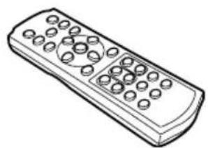
natural_image
Line drawing of a remote control with buttons and dials (no text or symbols)
● Computer connection cable (DVI/Mini D-sub, 15-pin) (1.8m/5.9') YH7-2052

natural_image
Line drawing of a broadband cable with two connected ports (no text or symbols)● Power cord (1.8m/5.9')

text_image
For Continental EuropeFor the U.S.A and Canada
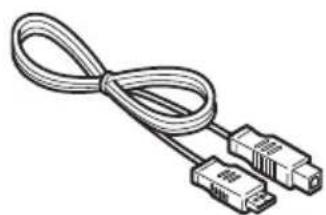
- USB cable (1.8m/5.9') YH7-2054
natural_image
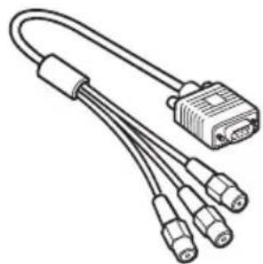
Line drawing of a broadband cable with two connectors (no text or symbols)● Component cable (RCA/Mini D-sub, 15-pin) (0.4m/1.3') YH7-2084
natural_image
Line drawing of a USB cable with multiple connectors (no text or symbols)- Carrying bag - Lens cap

natural_image
Line drawing of a baby seat with straps and a mirror (no text or symbols)- Lens cap strap

- User's Manual (CD-ROM)
- Warranty card
● Important Information and Quick Start Guide
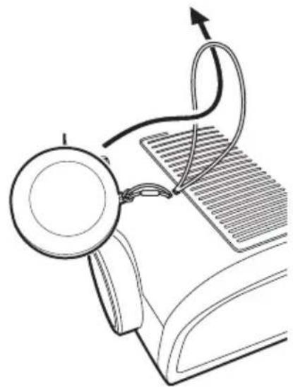
Installing the Lens Cap
As shown in the illustration on the right, let the lens cap strap through the hole on the lens cap, and then the lens cap strap insertion hole.
natural_image
Diagram of a medical or surgical procedure showing a magnifying glass connected to a curved tube with an arrow indicating direction (no text or symbols present)
- When the projector is not in use, attach the lens cap to protect the lens from dust and other foreign objects.
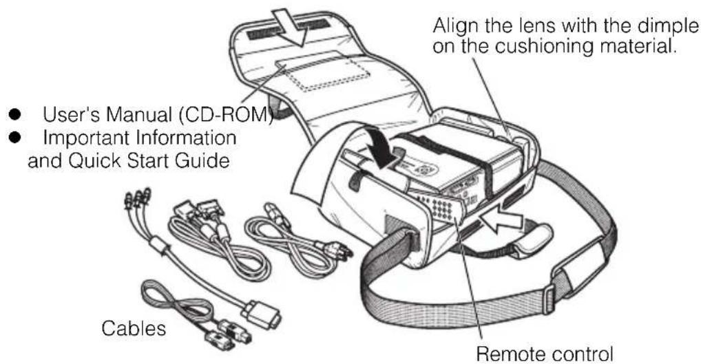
Putting the Projector in the Carrying Bag
Store the projector and the accessories in the carrying bag as shown in the illustration below.
The carrying bag is intended to protect the surfaces of the projector from dust or scratches, and is not designed to protect the projector from external shocks.
text_image
• User's Manual (CD-ROM) • Important Information and Quick Start Guide Cables Align the lens with the dimple on the cushioning material. Remote control
- Wait until the cooling fan stops before putting the projector in the carrying bag. Do not put the projector in the carrying bag until the cooling fan stops rotating. The projector may be damaged due to the heat.
- Attach the lens cap to the lens to protect it and put the projector in the carrying bag. Replace the adjustable foot to prevent the damage on the projector.
- When carrying the projector with it put in the carrying bag, do not give a shock to it, drop it, or place anything on it. The projector may be damaged or malfunctioned.
Part Names
Main Unit of Projector (SX7 MarkII is used in the following illustrations)
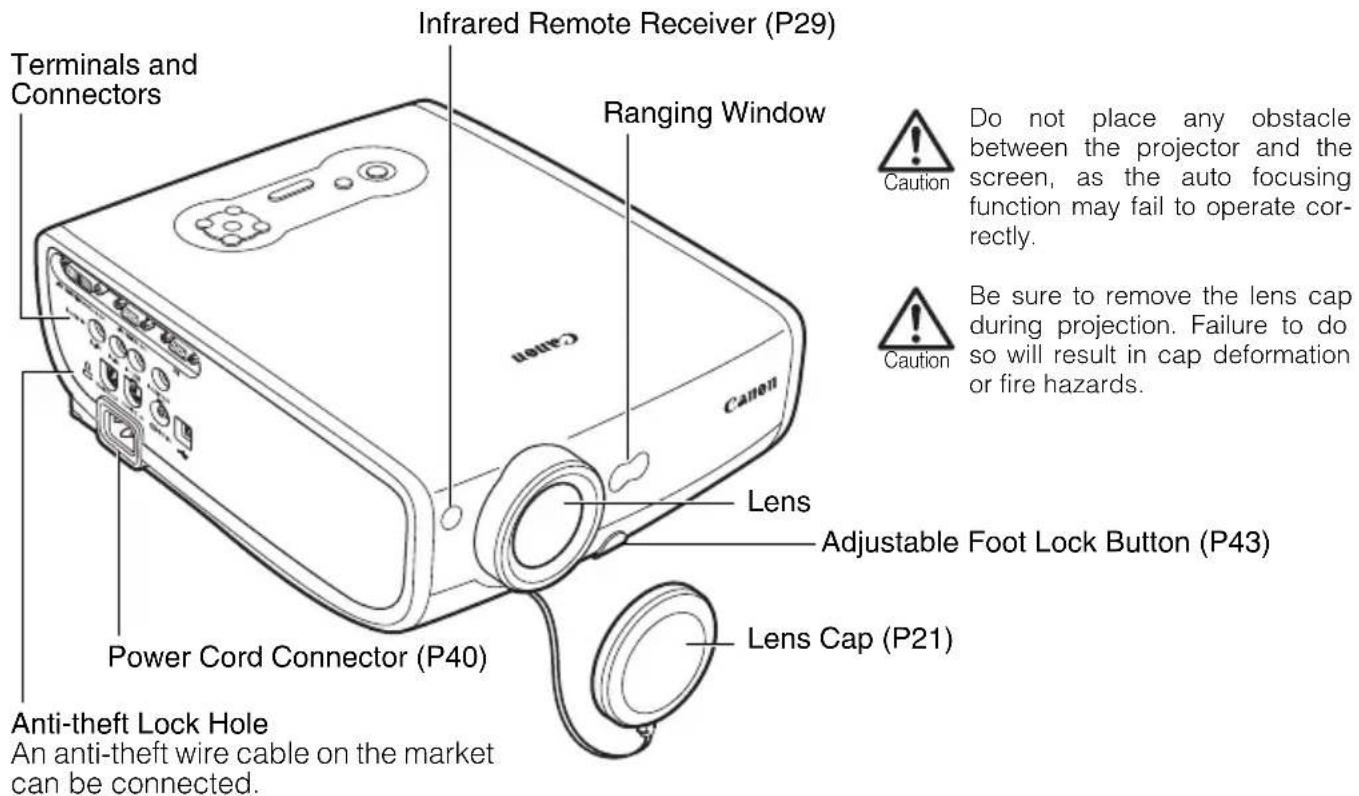
Front Side
text_image
Terminals and Connectors Infrared Remote Receiver (P29) Ranging Window Canon Canen Lens Adjustable Foot Lock Button (P43) Power Cord Connector (P40) Lens Cap (P21) Anti-theft Lock Hole An anti-theft wire cable on the market can be connected. Do not place any obstacle between the projector and the screen, as the auto focusing function may fail to operate correctly. Be sure to remove the lens cap during projection. Failure to do so will result in cap deformation or fire hazards.Rear Side
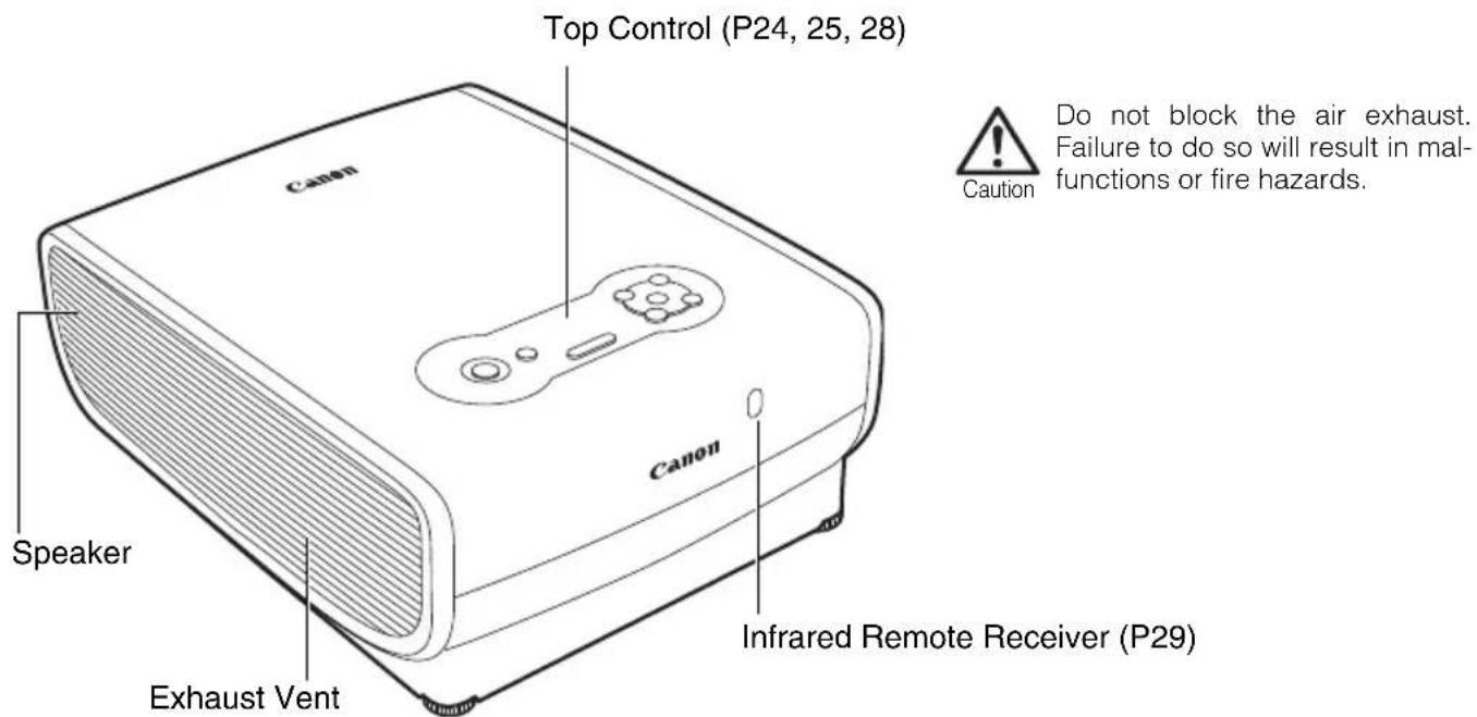
text_image
Top Control (P24, 25, 28) Canon Speaker Exhaust Vent Canon Infrared Remote Receiver (P29) Do not block the air exhaust. Failure to do so will result in mal- functions or fire hazards. CautionBottom Side
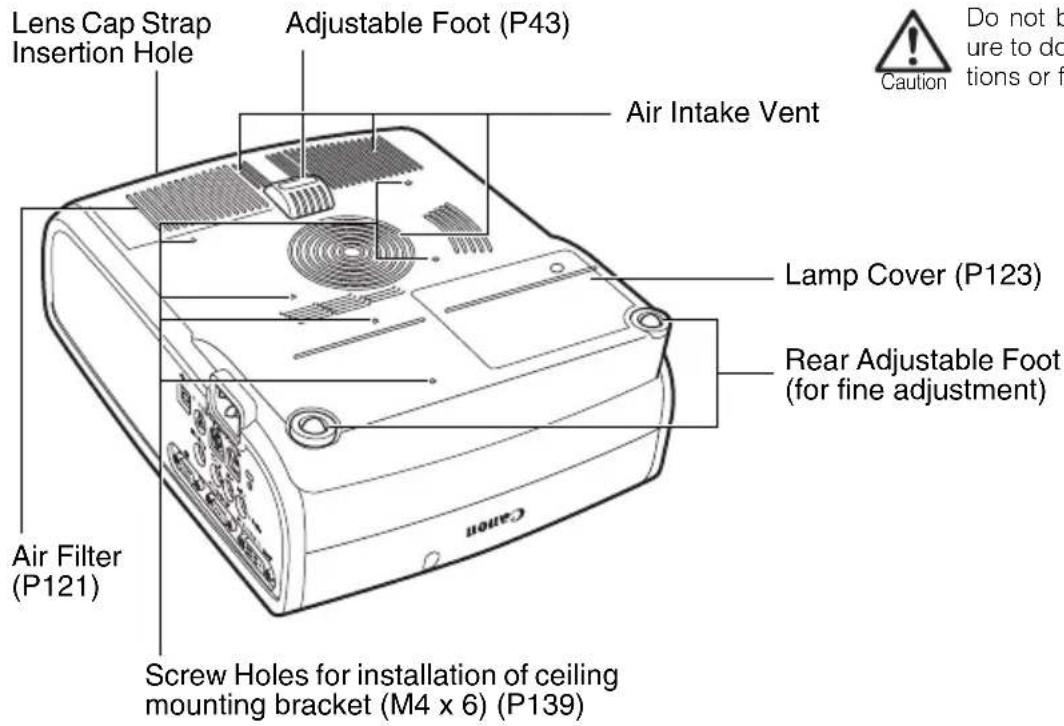
text_image
Lens Cap Strap Insertion Hole Adjustable Foot (P43) Air Intake Vent Lamp Cover (P123) Rear Adjustable Foot (for fine adjustment) Air Filter (P121) Screw Holes for installation of ceiling mounting bracket (M4 x 6) (P139) Caution Do not be ure to do tions or f
Do not block the air intake. Failure to do so will result in malfunctions or fire hazards.
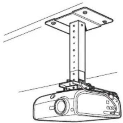
Mounting the Projector on the Ceiling
You can mount the projector on the ceiling.
You need an optional ceiling-mount hanger (part number: RS-CL07) and an optional ceiling-mount pipe (part number: RS-CL08 or RS-CL09) when appropriate.
Contact the dealer where you purchased the projector for more detailed information.
natural_image
Technical line drawing of a mechanical assembly with a vertical support and base component (no text or symbols)
● Make sure to use the optional ceiling mounting bracket.
- You should never install the ceiling mounting bracket by yourself.

- If you mount the projector on the ceiling, you have to invert the projected image by selecting [Image flip H/V] from the menu (P97).
Buttons on the Remote Control and Top Control
Remote Control
text_image
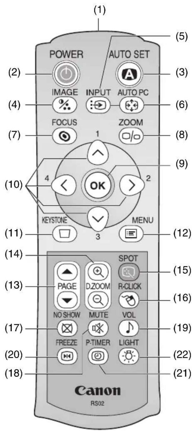
(1) POWER AUTO SET (2) IMAGE INPUT AUTO PC (3) (4) FOCUS 1 ZOOM (6) (7) (8) (9) (10) 4 OK 2 KEYSTONE MENU (11) 3 (12) (14) (13) PAGE D.ZOOM SPOT R-CLICK (15) (16) NO SHOW MUTE VOL (17) FREEZE P-TIMER LIGHT (19) (20) (21) (18) Canon RS02This projector can be operated using buttons on the remote control or the top control on the main unit.
The remote control allows you to operate all functions of the projector.
(1) Infrared Remote Emitter
Sends a signal to the infrared remote receiver on the main unit.
(2) POWER button (P40, 60)
Turns the projector on or off.
(3) AUTO SET button (P46, 70)
Performs auto adjustment on focusing, keystone distortion, screen color correction, and so on (Auto Setup Function).
(4) IMAGE button (P55)
Switches among image modes (image qualities).
(5) INPUT button (P48, 50, 70)
Switches among input signals.
(6) AUTO PC button (P54)
Adjusts tracking and so on automatically in accordance with signal from a computer when ANALOG PC-1 or ANALOG PC-2 is selected.
(7) FOCUS button (P51)
Adjusts focusing.
(8) ZOOM button (P42)
Adjusts the image size.
(9) OK button (P89)
Determines the item selected from the menu. Also works as the left button of a mouse under the USB connection (P82).
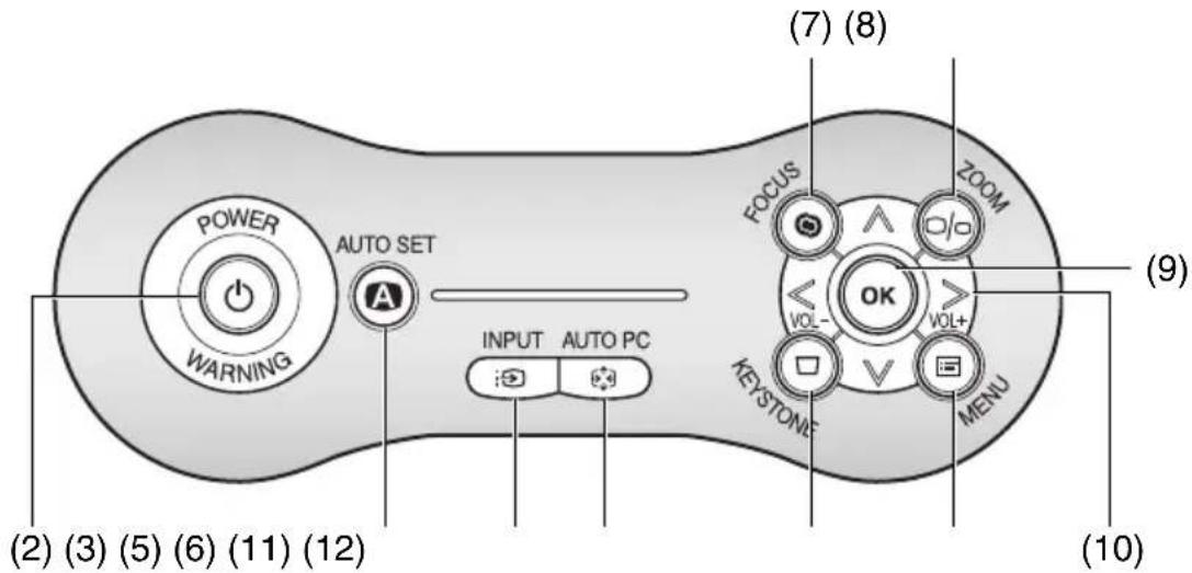
Top Control
text_image
POWER WARNING AUTO SET INPUT AUTO PC (2) (3) (5) (6) (11) (12) (7) (8) FOCUS ZOOM OK VOL- VOL+ KEYSTONE MENU (9) (10)(10) POINTER button (P87)
Selects the upper, lower, left, or right item in the menu. Also moves the mouse cursor under the USB connection.
On the top control, the [<] and [>] buttons also turn the volume up and down, respectively (P79).
(11)KEYSTONE button (P52, 59)
Corrects keystone distortion. The [D. image shift adjustment] screen will be displayed if you select [16:9 D. image shift] for [Screen aspect].
(12)MENU button (P87)
Displays a menu on the screen.
(13)PAGE button (P80)
Acts as the Page Up and Page Down keys on the computer keyboard under the USB connection.
Pressing ⬆ scrolls to the previous page and pressing ⬇ scrolls to the next page.
(14)D.ZOOM button (P81)
Zooms the image in or out digitally. Pressing @enlarges the image and pressing @reduces the image.
(15)SPOT button (P83)
Performs the spot light function.
(16) R-CLICK button (P82)
Acts as the right button of a mouse under the USB connection.
(17) NO SHOW button (P78)
Switch display/non-display of image.
(18)MUTE button (P79)
Mutes the sound.
(19) VOL button (P79)
Adjusts the sound volume.
(20) FREEZE button (P78)
Freezes the projected image.
(21) P-TIMER button (P80)
Displays the time elapsed since this button was pressed.
(22) LIGHT button (P29)
Turns on or off the lights of the remote control buttons.
Input Terminals on Main Unit
SX7 MarkII

text_image
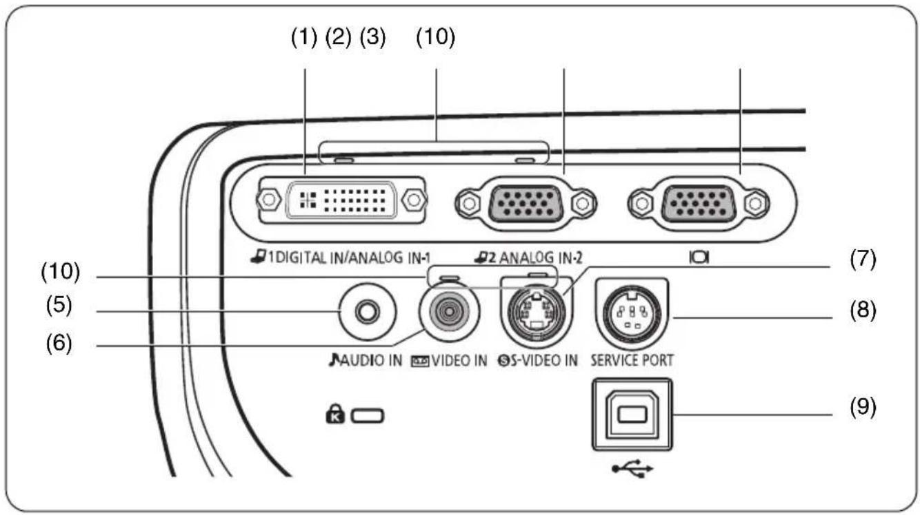
(1) (2) (3) (10) 1 DIGITAL IN/ANALOG IN-1 2 ANALOG IN-2 AUDIO IN AUDIO OUT SERVICE PORT S-VIDEO IN VIDEO IN (4) (5) (10) (9)SX60
text_image
(1) (2) (3) (10) (10) (5) (6) 1 DIGITAL IN/ANALOG IN-1 2 ANALOG IN-2 AUDIO IN VIDEO IN S-VIDEO IN SERVICE PORT (7) (8) (9)(1) Input Terminal-1 (DIGITAL IN/ANALOG IN-1) (P36, 37, 65)
Receives a digital (DIGITAL PC) and analog PC signal (ANALOG PC-1).
Receives a digital content image signal (DIGITAL VIDEO).
(2) Input Terminal-2 (ANALOG IN-2) (P36, 37, 64)
Receives an analog PC signal (ANALOG PC-2).
Receives a component and SCART image signal (COMPONENT/SCART).
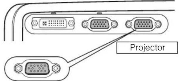
(3) Monitor Output Terminal ( ) (P38)
Outputs an analog PC signal to display an image on an external monitor.
(4) AUDIO OUT terminal (SX7 II) (P68)
The audio output terminal to output an audio to an external audio device.
It outputs the audio signal corresponding to the projected image signal.
(5) AUDIO IN terminal (P38, 39)
SX7 II: The audio input terminals corresponding to 3 image input systems.
Each terminal receives the audio signal corresponding to "DIGITAL PC/ANALOG PC-1", "ANALOG PC-2", and "S-VIDEO or VIDEO" from the left.
The internal speaker outputs the audio signal corresponding to the selected image signal.
SX60: The input terminal of an audio signal.
The internal speaker outputs the audio signal no matter what the image signal is inputted.
(6) VIDEO IN terminal (P66)
Receives a composite video signal from an AV equipment.
(7) S-VIDEO IN terminal (P66)
Receives an S-Video signal from an AV equipment.
(8) SERVICE PORT jack
Exclusively used by the service personnel (it is not used normally).
(9) USB terminal (P82)
Connected to the computer with a USB cable when the remote control is used as the mouse of the computer. (you cannot use this terminal to receive any video image)
(10)Input Terminal Indicator (P48, 70)
Indicates the input signal status.
Green : The input signal is confirmed and an image is projected.
Flashing green : The input signal is confirmed but no image is projected.
Off : An input signal is not confirmed (a cable is not connected).
Indicators on the Top Control
Top Control
text_image
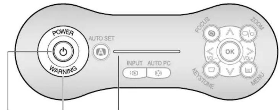
POWER WARNING AUTO SET INPUT AUTO PC FOCUS ZOOM OK VOL- VOL+ KEYSTONE MENU(1) (2) (3)
(1) POWER indicator (P40, 60, 111)
Indicates the projector status.
Red: The projector can be turned on.
Flashing red: The projector is being turned off (the lamp is being cooled).
Green: The projector is on.
Flashing green: The projector is being turned on.
Blink between red and green: The projector is under the power management mode.
(2) WARNING lamp (P126)
Flashes red when a problem has been detected on the projector.
(3) LED illumination lamp (P115)
Indicate the projector status with 3 blue LEDs.
Blinking from the left: The projector is being turning on.
Blinking from the right: The projector is being turned off.
Middle LED flashing slowly: The image is blackened out (NO SHOW).
Left and right LEDs flashing slowly:
The image is stopped (FREEZE).
Preparing the Remote Control
Installing Remote Control Batteries
1 Open the battery compartment lid. Slide the lid with it pressed down.
2 Insert batteries. Insert new two AAA-size batteries in the compartment with the + and - poles positioned correctly.
3 Replace the compartment lid.

natural_image
Line drawing of a remote control casing with a black arrow indicating left side (no text or symbols)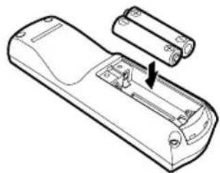
natural_image
Line drawing of a remote control device with a battery and switch (no text or symbols)
natural_image
Line drawing of a remote control device with handle and keypad (no text or symbols)
- You can check the batteries of the remote control by pressing the [LIGHT] button. If all buttons on the remote control do not light when the [LIGHT] button is pressed, or buttons are inoperative when you attempt to operate the projector, replace with new batteries. - It is recommended to check the batteries before a presentation.
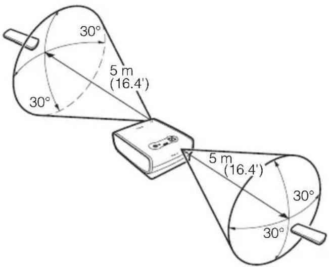
Remote Control Operating Range
Point the remote control to the infrared remote receiver on the front or rear of the projector whenever pressing any button.
- Use the remote control within a distance of approximately 5 m (16.4') from the projector.
- Use the remote control within an angle of 30^ in any direction from directly in front of the infrared remote receiver.
text_image
30° 5 m (16.4') 30° 5 m (16.4') 30° 30°
The remote control may be inoperative if:
● There is an obstacle between the remote control and main unit.
- The infrared remote receiver on the main unit is exposed to direct sunlight or strong light of lighting equipment.

● The remote control uses infrared light.
- When you use two projectors at the same time, you can change the channel settings to prevent the two remote controls from interfering with each other (P115).
SETTING UP THE PROJECTOR
Table of contents/Safety Instructions
Before Use
Setting Up the Projector
Projecting an Image from the Computer
Projecting an Image from AV Equipment
Useful Functions Available During a Presentation
Setting Up Functions from Menus
Maintenance
Troubleshooting
Appendix
Index
Setting Up the Projector
Determining the Distance to the Screen
The projected image size is determined by the distance between the projector lens and the screen. Select the place where the desired image size is obtained according to the illustration shown below.

text_image
8.9 m (29.2') 5.9 m (19.4') 4.5 m (14.8') 2.4 m (7.9') 1.2 m (3.9') 40" 80" 48" 150" 90" 200" 120" 300" Zoom (max.) 182" Zoom (min.) H1 H2 H1:H2=9:1 Optical axis when image is projected at right angle to the screen. Screen| Screen size(W x H) cm | 40"81 x 61 | 60"122 x 91 | 80"163 x 122 | 100"203 x 152 | 150"305 x 229 | 182"370 x 277 | 200"406 x 305 | 250"508 x 381 | 300"610 x 457 | |
| Projection distance | Zoom (max) | 1.2 m(3.9') | 1.8 m(5.9') | 2.4 m(7.9') | 3.0 m(9.8') | 4.5 m(14.8') | 5.4 m(17.7') | 5.9 m(19.4') | 7.4 m(24.2') | 8.9 m(29.2') |
| Zoom (min) | 2.0 m(6.6') | 2.9 m(9.6') | 3.9 m(12.9') | 4.9 m(16.1') | 7.4 m(24.2') | 9.0 m(29.5') | - | - | - | |
| H1 | 55 cm(1.8') | 82 cm(2.7') | 110 cm(3.6') | 137 cm(4.5') | 206 cm(6.8') | 250 cm(8.2') | 274 cm(9.0') | 343 cm(11.3') | 411 cm(13.5') | |
| H2 | 6 cm(0.2') | 9 cm(0.3') | 12 cm(0.4') | 15 cm(0.5') | 23 cm(0.8') | 28 cm(0.9') | 30 cm(1.0') | 38 cm(1.2') | 46 cm(1.5') | |
H1 and H2: The height of the screen from the intersection of optical axis and screen surface when an image is projected at right angle to the screen.
- Install the projector at the position where the projection distance is between approximately 1.2 m (3.9') to 9 m (29.5'). If the installation position is too close or too far, the image is out of focus or the screen becomes dark, respectively.
- The sizes in the above table have been obtained assuming that the aspect ratio is 4:3. They may vary from the actual sizes depending on the type of the projected image.
- Select the appropriate setting for [Screen aspect] with respect to the your screen (4:3 or 16:9).
Refer to pages 59, 74, and 101 for more detailed information on [Screen aspect].

- For the relationship between the screen size and projection distance, see the table on page 133.
- You can also adjust the image size with the zoom function (P42).
Determining the Installation Position
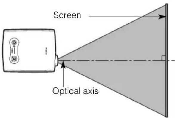
Placing in Front of the Screen
Place the projector perpendicular to the screen as far as possible.

- A slight error in the projection angle can be corrected using the [KEYSTONE] button (P52).
text_image
Screen Optical axisPlacing on a Level Place
Place the projector on a level place as far as possible.

● A slight tilt can be corrected using the rear adjustable foot. (P43)
● Make sure that the installation position is free from any obstacle that may block the exhaust vent (fan) on the right side of the projector and the air intake vent on the bottom of the projector.
- The screen must not be exposed to direct sunlight or light from lighting equipment. In a bright room, it is recommended to limit ambient lighting in order to improve the image quality.

natural_image
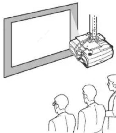
Line drawing of a Canon portable radio unit with no text or symbols on the device itselfCeiling Mounting or Rear Projection
You can mount the projector on the ceiling (Ceiling mounted) with it turned up side down or place it behind the screen (Rear) if you use a translucent screen. For ceiling mounting or rear projection, you have to invert the projected image. (P97).
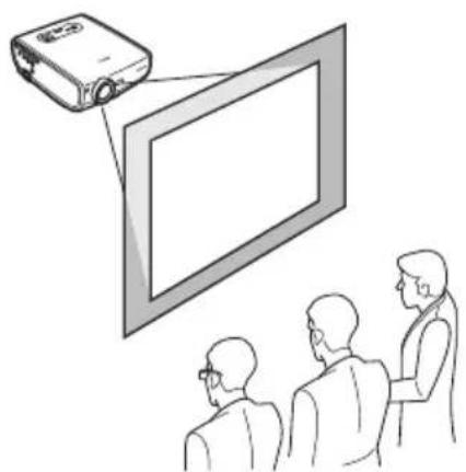
natural_image
Illustration of a projector projecting a screen to three people (no text or symbols present)Ceiling Mounting Rear Projection
natural_image
Illustration of a projector projecting onto a screen to three people watching (no text or symbols present)PROJECTING AN IMAGE FROM THE COMPUTER
Table of contents/Safety Instructions
Before Use
Setting Up the Projector
Projecting an Image from the Computer
Projecting an Image from AV Equipment
Useful Functions Available During a Presentation
Setting Up Functions from Menus
Maintenance
Troubleshooting
Appendix
Index
Projecting an Image from the Computer
Connecting the Projector to the Computer
Connect the projector to the computer.
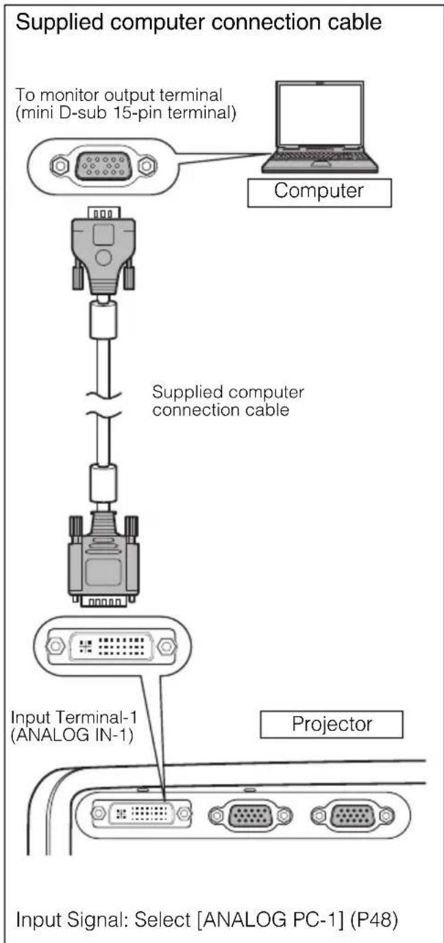
Connecting to Video Terminals
flowchart
graph TD
    A["Input Signal: Select [ANALOG PC-1"] (P48)] --> B["Input Terminal-1 (ANALOG IN-1)"]
    B --> C["Supplied computer connection cable"]
    C --> D["Computer"]
    style A fill:#f9f,stroke:#333
    style B fill:#ccf,stroke:#333
    style C fill:#cfc,stroke:#333
    style D fill:#fcc,stroke:#333
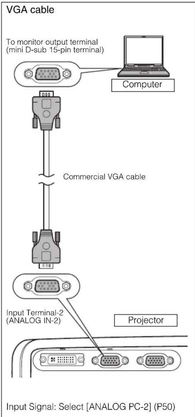
flowchart
graph TD
    A["Computer"] -->|To monitor output terminal (mini D-sub 15-pin terminal)| B["Commercial VGA cable"]
    B --> C["Input Terminal-2 (ANALOG IN-2)"]
    C --> D["Projector"]
    D --> E["Input Signal: Select [ANALOG PC-2"] (P50)]

- To ensure projection of high-resolution high-quality images, it is recommended to use high-performance cables.
- An adapter may be required depending on the shape of the connector on the computer. For more detailed information, refer to your computers instruction manual.

● Before connecting cables, turn off both the projector and computer.
- It may project an image inappropriately when projecting the digital PC signal in 1280 x 1024 or 1400 x 1050 depending on the type of computer or DVI cable.
- The USB terminal is used to use the remote control as the computer mouse. An image cannot be projected simply by connecting the USB cable.
DVI cable
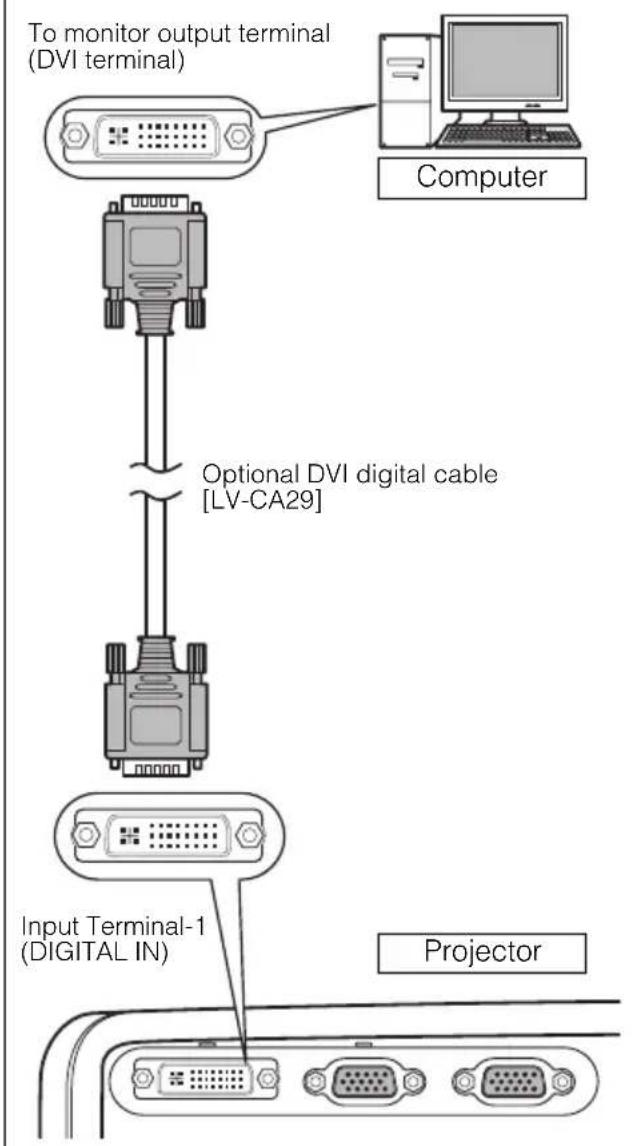
flowchart
graph TD
    A["To monitor output terminal (DVI terminal)"] --> B["Optional DVI digital cable [LV-CA29"]]
    B --> C["Input Terminal-1 (DIGITAL IN)"]
    C --> D["Projector"]
Input Signal: Select [DIGITAL PC] (P48)
5-BNC cable

text_image
To monitor output terminal (5-BNC output terminal) Computer Extension cable Commercial 5-BNC cable (for 5-BNC/ mini D-Sub 15-pin) Commercial 5-BNC extension cable Input Terminal-2 (ANALOG IN-2) ProjectorInput Signal: Select [ANALOG PC-2] (P50)
Connecting to an External Monitor
You can display an image from the projector to an external monitor.
VGA cable
text_image
ProjectorTo monitor output terminal (mini D-sub 15-pin terminal)

text_image
Commercial VGA cable External monitorImage input terminal (mini D-sub 15-pin terminal)

- You can connect one external monitor. The multi-monitor display is not supported.
● The projected image is displayed on the external monitor. - You cannot output the input signal to the external monitor if it is DIGITAL PC.
Connecting to AUDIO IN Terminals (SX7 II)
Connect an audio cable to the AUDIO IN terminal corresponding to the input image signal if you want to use the projector's speaker.
Audio cable
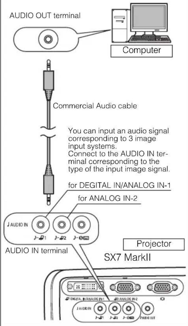
text_image
AUDIO OUT terminal Computer Commercial Audio cable You can input an audio signal corresponding to 3 image input systems. Connect to the AUDIO IN ter- minal corresponding to the type of the input image signal. for DEGITAL IN/ANALOG IN-1 for ANALOG IN-2 AUDIO IN terminal Projector SX7 MarkII J AUDIO IN J- J1 J- J2 J- J3 J AUDIO IN J- J1 J- J2 J- J3 AUDIO OUT
● The speaker outputs the audio signal corresponding to the selected image signal.
- Use an audio cable without a built-in resistor. Using an audio cable with a built-in resistor turns down the sound.
- Connect the audio cable between the AUDIO OUT terminal and an external audio-visual equipment if you want to output the audio signal to the audio-visual equipment (P68).
● The built-in speaker is monaural.
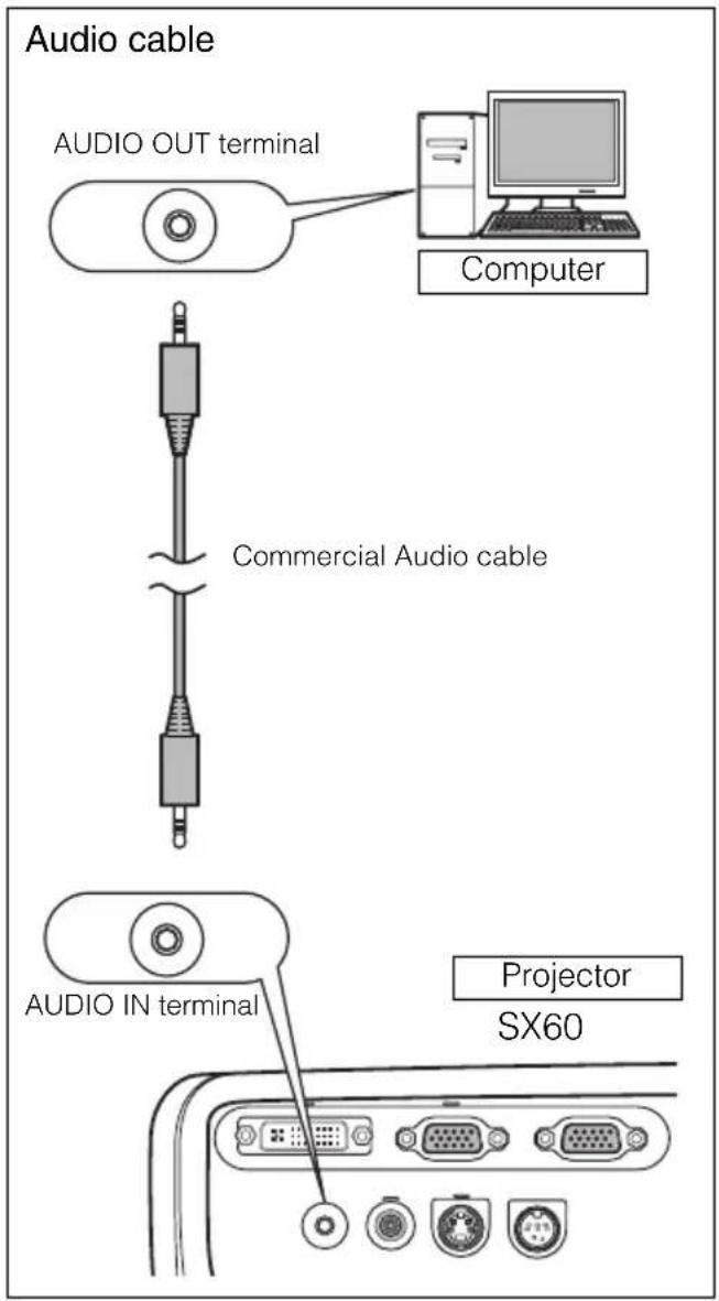
Connecting to AUDIO IN Terminals (SX60)
Connect the audio cable to the AUDIO IN terminal if you want to use the projectors speaker.
text_image
Audio cable AUDIO OUT terminal Computer Commercial Audio cable AUDIO IN terminal Projector SX60
- Use an audio cable without a built-in resistor. Using an audio cable with a built-in resistor turns down the sound.
● The built-in speaker is monaural. - The speaker plays the sound from the equipment which the audio cable is connected to regardless of the image input signal.
Starting Projection
Connect the power cord and turn on the projector to start the projection.

- Once the projector is turned off, it cannot be turned on for a while. Wait until the lamp is cooled down and the [POWER] indicator lights in red.

Connect the Ground Terminal
Connect the ground terminal on the power plug to ground. Otherwise, the operating computer may suffer electromagnetic radiation problems and poor reception by TV and radio.
Unplug the Power Cord When the Projector is Not in Use
The projector constantly consumes approximately 7W power even when it is turned off. To ensure safety, malfunction prevention, and power saving, remove the power plug from the AC outlet when the projector is not used for an extended period of time.
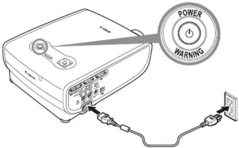
1 Connect the power cord.
Fully insert the power cord plug into the socket.
The [POWER] indicator flashes red.
text_image
POWER WARNING2 Remove the lens cap and press the [POWER] button.
The [POWER] indicator flashes green, and then lights in green.
![CANON REALiS SX7 Mark II D - Remove the lens cap and press the [POWER] button. - 1](/content/2026/06/1190229/images/6184f0b63f095326172201b2a6e993e09ea033490fec4086533e7e30c4730630.jpg)
text_image
POWER AUTO SET IMAGE INPUT AUTO PC POWER WALKING![CANON REALiS SX7 Mark II D - Remove the lens cap and press the [POWER] button. - 2](/content/2026/06/1190229/images/09b50ad37c901dad1e8f93f298d02f45d0a2ead146571527e64487ad89da2379.jpg)
text_image
Do you know about Auto Setup? It automatically performs the focus adjustment, keystone adjustment, input signal settings, and screen color adjustment for projecting an optimum image. OKThe countdown window is displayed for approximately 20 seconds, and then the guiding message for the auto setup function appears.
Adjust the focus by performing the auto setup or the focus adjustment if you cannot read the message due to out of focus. (P46, 51)
The LED illumination lamp blinks blue until the projection is started.
To project an image immediately, press the [OK] button.
![CANON REALiS SX7 Mark II D - Remove the lens cap and press the [POWER] button. - 3](/content/2026/06/1190229/images/8dd9344e1cbed2daf4c99c945bd979d7009f1ea9d22a80a23bed0543dcdd9c78.jpg)
● Enter a password if the Password input screen appears (P116, 117).
- You can turn on the projector by connecting the power cord without pressing the [POWER] button (direct power on) (P112).
● You can display a specified Logo on the countdown screen (P100).
- You can specify whether to enable or disable the LED illumination lamp (P115).
- You can skip the countdown window (P100).
Selecting a Language
A window appears when the projector is turned on for the first time. You can select a language to be used by the projector for displaying menus and so on in the window. Select your language as shown below.
Select a language with the POINTER buttons and press the [OK] button.
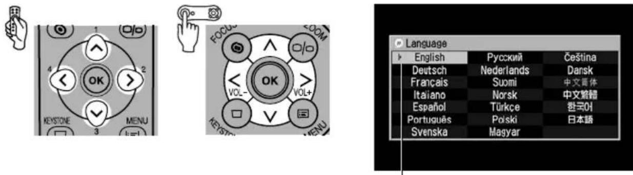
An item highlighted in orange will be selected.
- Adjust the focus by performing the focus adjustment if it is out of focus (P51).
● You can change the language from the menu at a later time (P113).
Adjusting the Image
Adjusting the Image Size (ZOOM)
Adjust the image size in accordance with the screen.
1 Press the [ZOOM] button.
The Zoom adjustment window appears.
![CANON REALiS SX7 Mark II D - Press the [ZOOM] button. - 1](/content/2026/06/1190229/images/1fd6cf9954459b6f3ed6b025bdc8ff13f7c2d8f551aa83a17f88722260912ff0.jpg)
text_image
FOCUS ZOOM 1 2 4 FOCUS ZOOM < OK >![CANON REALiS SX7 Mark II D - Press the [ZOOM] button. - 2](/content/2026/06/1190229/images/1097d1de4082f5a53d68d4f5f044adff98a049c016b37ae385169f811f8e8a01.jpg)
text_image
Zoom adjustment2 Adjust the image size.

text_image
1 O/O 4 OK 2 KEYSTONE 3 MENU 3 FOCUS VOL- OK VOL+ VOL- KESSTONE MENUZoom in:
Press [λ] for rough adjustment.
Press [>] for fine adjustment.
Zoom out:
Press [ ] for rough adjustment.
Press [<] for fine adjustment.

flowchart
graph TD
    A["User Interaction"] --> B["Group 1"]
    A --> C["Group 2"]
    A --> D["Group 3"]
    B --> E["User Group 1"]
    C --> F["User Group 2"]
    D --> G["User Group 3"]
3 Press the [OK] button.
![CANON REALiS SX7 Mark II D - Press the [OK] button. - 1](/content/2026/06/1190229/images/af8069c04d60b6f13ffad69e14449525ba9c8e3136eabc5e498d9b5baebe4ad0.jpg)
text_image
1 O/O 4 OK 2 KEYSTONE 3 MENU FOCUS VOL- OK VOL+ KEYSTONE MENU![CANON REALiS SX7 Mark II D - Press the [OK] button. - 2](/content/2026/06/1190229/images/d6c93ed55d1039a4e0804a79d76c48a37963b4757758916b9396aa9ce91a9a16.jpg)
- Change the projector installation position if your desired image size is too large or too small to adjust with the zoom function (P32).
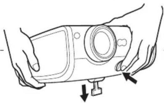
Adjusting the Projection Angle
You can adjust the projection angle with the adjustable foot.
1 Lift the front side of the projector and push the adjusting foot lock button.
The adjustable foot extends.
2 Adjust the projection angle while pushing the adjustable foot lock button, and then release the lock button.
The adjustable feet is fixed.

- With the adjustable foot, the projection angle can be adjusted up to 10 degrees.
- If the projector is tilting in the lateral direction, use the rear adjustable feet on both sides to adjust its angle. You can adjust up to 10mm with one foot.
natural_image
Line drawing of hands holding a device with a knob and a button, showing mechanical components (no text or symbols)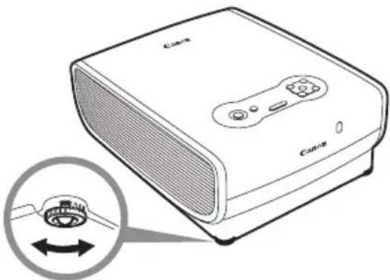
natural_image
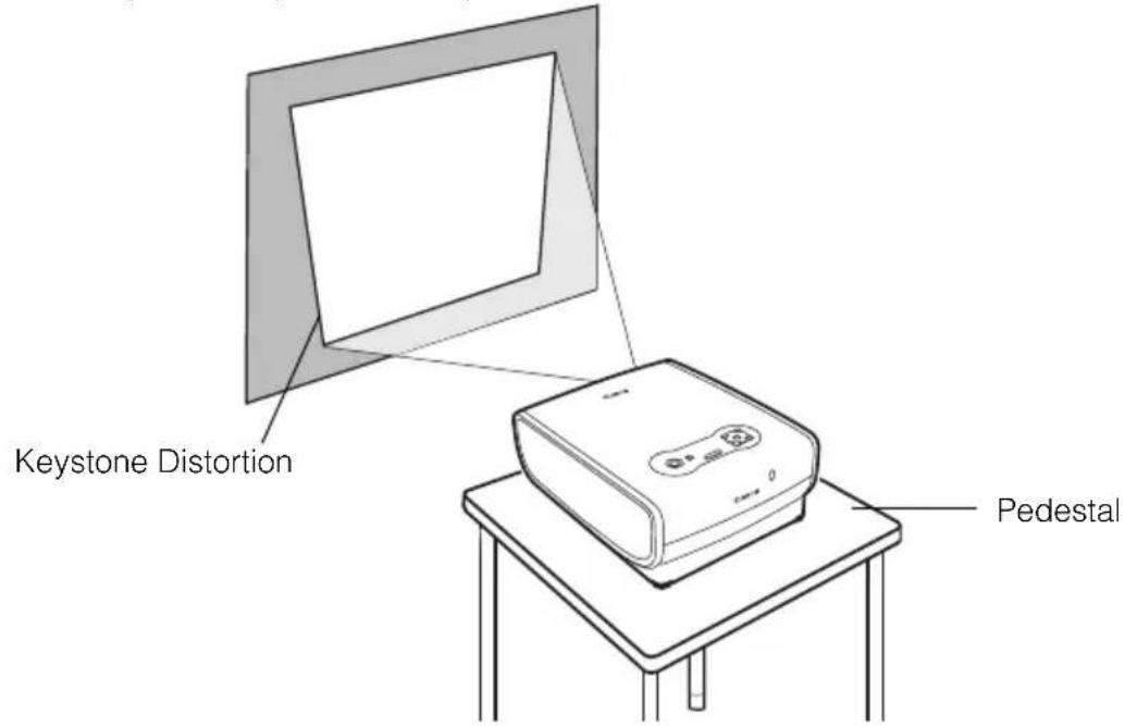
Illustration of a Canon portable electronic device with a close-up inset showing the rotary knob (no text or symbols on the device itself)If Keystone Distortion is Too Large
Extending the adjustable foot too far causes keystone distortion. If the distortion is too large, adjust the height of the projector with a pedestal.
The keystone distortion can be corrected with the Auto keystone function or by pressing the [KEYSTONE] button. (P46, 52, 70)
text_image
Keystone Distortion PedestalPreparing the Computer
Determining the Output Resolution of the Computer
To make the most of the display performance of this projector, set output signal resolution of the computer to an optimum value.
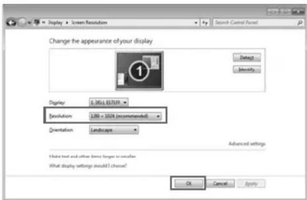
Windows 7
- Open the [Control Panel] from the start menu, then select [Appearance and Personalization] – [Adjust screen resolution] in the [Control Panel Home].
- Click the [Resolution] pull-down menu and move the slider to select "1400 x 1050". If this resolution is not available, select the highest resolution under 1400 x 1050.
- Click the [OK] button.
text_image
Display ▶ Screen Resolution Search Control Panel Change the appearance of your display Display: 1.2614.837549 Resolution: 1200 x 1024 (recommended) Orientation: Landscape Advanced settings Make text and other items longer or shorter What display settings should I choose? OK Cancel ApplyWindows Vista
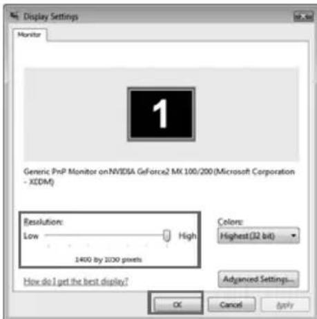
- Open the [Control Panel] from the start menu, then select [Appearance and Personalization] – [Adjust screen resolution] in the [Control Panel Home].
- Select "1400 x 1050 pixels" or a resolution closest to the output signal resolution of the computer.
- Click the [OK] button.
text_image
Display Settings Monitor Generic PnP Monitor on NVIDIA GeForce2 MX 100/200 (Microsoft Corporation - XCOM) Resolution: Low High 1400 by 2000 pixels Colors: Highest (32 bit) Advanced Settings... How do I get the best display? OK Cancel ApplyWindows XP
- Right-click on the desktop background and select [Properties] to open the [Display Properties].
- Click the [Settings] tab, and under [Screen Resolution], select "1400 x 1050 pixels" or a resolution closest to the output signal resolution of the computer.
- Click the [OK] button.

text_image
Display Properties Themes Desktop Screen Save Appearance Settings Drag the monitor icons to watch the physical arrangement of your monitors. 1 2 Display 2: (Default Monitor) on Intel(R) 82945G Express Chipset Family Screen resolution More Less 1400by 1050 pixels Color quality Highest [32 bit] Use this device as the primary monitor Extend my Windows desktop onto this monitor. Identity Troubleshoot Advanced OK Cancel ApplyMacintosh OSX
- Open the Apple Menu and select [System Environment Setting].
- In the System Environment Setting window, click the [Displays] icon to display the Display window.
- Select the [Display] tab and select "1400 x 1050" or a resolution closest to the output signal resolution of the computer from the [Resolution] list.
- Close [System Environment Setting] window.

text_image
Show All Display Color Resolutions: 640 x 480 (stretched) 640 x 512 800 x 600 800 x 600 (stretched) 800 x 640 1024 x 768 1024 x 768 (stretched) 1024 x 820 1280 x 960 1400 x 1050 Colors: Millions Refresh Rate: 75 Hertz Detect Displays Show displays in menu bar
For SX7 MarkII/SX60
- If the display resolution of the computer is set to SXGA (1280 by 1024 dots) or WXGA (1280 by 768 dots), it is recommended to select [True size] as the screen mode (P90).
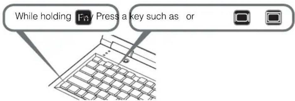
Projecting the Image from the Notebook Computer
You can turn on the external monitor output via keyboard operation.
To turn on the external monitor output, press an icon for an external monitor or a function key ([F1] to [F12]) while holding [Fn] key down.
text_image
While holding Key Press a key such as or
- The function keys you use and the method used to turn on the external monitor output vary depending on the model. For details, see the instructions of your notebook computer.
Performing the Auto Setup
With the auto setup function, the following set of adjustments is performed automatically when projecting an image from a computer. You can start the projection only with this operation if the input signal has been appropriately selected.
Auto focus
Adjusts the focusing automatically.
Auto keystone
Corrects the keystone distortion (in the vertical direction) automatically.
Auto input
Sets the image input signal automatically.
Auto screen color\*
Performs the screen color correction (white balance adjustment) automatically.
*: This is not enabled at the factory.

- Among 4 functions above, the function that has been enabled in the menu is performed during the auto setup. "Auto focus", "Auto keystone", and "Auto input" are enabled in the factory.
- You can manually set or adjust each function. You can set or adjust a specific function independently if you press the [AUTO SET] button during the manual adjustment.
- Select [Greenboard] from [Screen color] when using a greenboard (dark green) as a screen (P98).
- The auto focusing and the screen color correction may not be performed properly depending on the brightness of the room or the condition of the screen. Adjust the image manually if such is the case.
- If you select [16:9] for [Screen aspect], [Auto screen color] may not correct the screen color properly. If such is the case, correct it manually.
- If you select [16:9 D. image shift] for [Screen aspect], the auto setup function will be disabled.
- If you project an image straight up or down, [Auto focus] and [Auto keystone] will be disabled.
1 Select an input signal.
Select an appropriate input signal by following the steps in the "Selecting an Input Signal" section at the page 48 if you change the input signal due to changing the connection to the computer or so.
Skip this step if you have not changed the input signal since the last projection.
2 Press the [AUTO SET] button.
The Auto setup window appears.
![CANON REALiS SX7 Mark II D - Press the [AUTO SET] button. - 1](/content/2026/06/1190229/images/cd4e89c7c3310b9f6c11ad4adb0731cd48422227978f3b12c9678979d0d4872c.jpg)
text_image
POWER AUTO SET A IMAGE INPUT AUTO PC POWER AUTO SET A![CANON REALiS SX7 Mark II D - Press the [AUTO SET] button. - 2](/content/2026/06/1190229/images/101359177cb2e20acd484db239aefa488198e4bb0e2541c2598f74aa97baa407.jpg)
text_image
Auto setup Auto focus Auto keystone Auto input Auto screen color Execute Auto Setup? OK Cancel3 Press the [AUTO SET] button again.
One or more functions highlighted in black are performed automatically.
![CANON REALiS SX7 Mark II D - Press the [AUTO SET] button again. - 1](/content/2026/06/1190229/images/3fd50419fc8d8e05cbec243fa69d6cb25c747c7e7c0945ac21eb8551b6e77d72.jpg)
text_image
POWER AUTO SET IMAGE INPUT AUTO PC POWER AUTO SET A![CANON REALiS SX7 Mark II D - Press the [AUTO SET] button again. - 2](/content/2026/06/1190229/images/05177a39236a72adb00f4a46d332c9da6f90313d187d635e6932dcd6ee198c38.jpg)
- You can perform this step by selecting [OK] with the [<] button, and then pressing the [OK] button.
Selecting an Input Signal
You can select an input signal type.
Select an input signal from the followings:
ANALOG PC-1 : Analog signal Connecting with a DVI/Mini D-sub 15-pin cable
(supplied cable)
DIGITAL PC : Digital signal Connecting with a DVI digital cable
ANALOG PC-2 : Analog signal Connecting with a VGA cable or 5-BNC cable
Select an appropriate input signal before starting the auto setup function by following the steps below if you change the input signal due to changing the connection to the computer or so.

- An LED for a terminal flashes in green if a cable is connected and an input signal is confirmed. An LED for a terminal turns on if the projected image is obtained through the terminal (P26, 27).
- Connecting a DVI cable to Input Terminal-1, select the appropriate input signal with the [INPUT] button in accordance with the setting on the computer (digital signal/analog signal).
■ Selecting [ANALOG PC-1] or [DIGITAL PC]
1 Press the [INPUT] button.
The [INPUT] window appears.
![CANON REALiS SX7 Mark II D - Press the [INPUT] button. - 1](/content/2026/06/1190229/images/39d301b3575d53f435a01e6647ad501d0cf0168b1676bea7afad0f0341d812db.jpg)
text_image
IMAGE INPUT AUTO PC % % FOCUS ZOOM 1 OUTPUT AUTO PC![CANON REALiS SX7 Mark II D - Press the [INPUT] button. - 2](/content/2026/06/1190229/images/e87d78e1ad3b9b7e1a16fe37b4b9b2e10dd0154bf42a61309fb6f27d073d95e7.jpg)
text_image
INPUT ANALOG PC-1 ANALOG PC-2 COMPONENT VIDEO S-VIDEO DIGITAL PC ANALOG PC-1 DIGITAL VIDEO2 Select [ANALOG PC-1] or [DIGITAL PC] in the menu with the [INPUT] button.
The selection is toggled through available input signal types from above.
![CANON REALiS SX7 Mark II D - Select [ANALOG PC-1] or [DIGITAL PC] in the menu with the [INPUT] button. - 1](/content/2026/06/1190229/images/0f724dc9e0bb32c474f4f1b930d486cb4e8174fff62cad690d0b0f8911cc9c69.jpg)
text_image
IMAGE INPUT AUTO PC FOCUS ZOOM INPUT AUTO PC![CANON REALiS SX7 Mark II D - Select [ANALOG PC-1] or [DIGITAL PC] in the menu with the [INPUT] button. - 2](/content/2026/06/1190229/images/ccca960e0f13360fb8b27494b440c6126ebf37cb7a819de941af1a42990794c7.jpg)
- You can select any input signal type from all options through the [v] / [λ] button.
3 If the target input signal is unavailable from the list at the left, press the [>] button, and then press the [v] / [^] button to select the target input signal from the list at the right.
![CANON REALiS SX7 Mark II D - Select [ANALOG PC-1] or [DIGITAL PC] in the menu with the [INPUT] button. - 3](/content/2026/06/1190229/images/ab9a1b6020ee239d5cbfee76c767a0dcc4dc6f9b9b93f4f16f38cdf84c25907f.jpg)
text_image
1 O/O 4 OK 2 KEYSTONE 3 MENU 1=1 FOCUS VOL- VOL+ VOL- MENU![CANON REALiS SX7 Mark II D - Select [ANALOG PC-1] or [DIGITAL PC] in the menu with the [INPUT] button. - 4](/content/2026/06/1190229/images/159a4e966d4c207725b27394a7e3b778fa62aab8e8bcbe4450b6956f15f7c88e.jpg)
text_image
INPUT ANALOG PC-1 ANALOG PC-2 COMPONENT VIDEO S-VIDEO DIGITAL PC ANALOG PC-1 DIGITAL VIDEO4 Press the [OK] button.
![CANON REALiS SX7 Mark II D - Select [ANALOG PC-1] or [DIGITAL PC] in the menu with the [INPUT] button. - 5](/content/2026/06/1190229/images/5ba3c32994b68478425b529d0ce701689c14af711c1d348c2a411a9652f64d1b.jpg)
text_image
1 O/O 4 OK 2 KEYSTONE 3 MENU 3 FOCUS VOL- VOL+ KEYSTONE 3 MENU■ Selecting ANALOG PC-2
 \- Select [ANALOG PC-2] for Input Terminal-2.1 Press the [INPUT] button.
The [INPUT] window appears. text_image
IMAGE INPUT AUTO PC % % % % % % % % % % % % % % % % % % % % % % % % % % % % % % % % % % % % % % % % % % % % % % % % % % % % % % % % % % % % % % % % % % % % % % % % % % % % % % % % % % % % % % % %text_image
INPUT ANALOG PC-1 ANALOG PC-2 COMPONENT VIDEO S-VIDEO ANALOG PC-2 SCART2 Select the second top item in the menu with the [INPUT] button.
The selection is toggled through available input signals from above. text_image
IMAGE INPUT AUTO PC % % FOCUS ZOOM 1 OUTPUT AUTO PC3 If the ANALOG PC-2 is unavailable from the list at the left, press [>], and then press [v] / [λ] to select the ANALOG PC-2 from the list at the right.
text_image
1 OK 2 3 4 KEYSTONE MENU FOCUS VOL- OK VOL+ MENUtext_image
INPUT ANALOG PC-1 ANALOG PC-2 COMPONENT VIDEO S-VIDEO ANALOG PC-2 SCART4 Press the [OK] button.
text_image
1 OK 2 3 4 KEystone MENU FOCUS VOL- OK VOL+ KEYSTONE MENUAdjusting the Focus
You can adjust the focus. Follow the steps below to adjust the focus manually if the Auto setup function (Auto focus) does not adjust the focus appropriately. 1 Press the [FOCUS] button. The Focus adjustment window appears. text_image
FOCUS ZOOM 1 2 4 FOCUS ZOOM < OK >text_image
Focus adjustmenttext_image
1 2 3 4 OK KEYSTONE MENU FOCUS VOL- OK VOL+ KEYSTONE MENUtext_image
1 O/O 4 OK 2 KEystone 3 MENU FOCUS VOL- OK VOL+ KEYSTONE MENUAdjusting Keystone Distortion
The Auto setup function (Auto keystone) automatically adjusts the keystone distortion in a longitudinal direction. Follow the steps below if the function does not adjust the distortion appropriately or you want to adjust the keystone distortion in a horizontal direction.1 Press the [KEYSTONE] button.
The [Keystone adjustment] windows appears. text_image
KEYSTONE 3 MENU SPOT OK VOL- VOL+ KEYSTONE MENUtext_image
Keystone adjustment +0 < +0 >2 Press the POINTER buttons to adjust the focus.
text_image
1 OK 2 3 4 KEystone MENU FOCUS < VOL- VOL+ VOL- VOL+flowchart
graph LR
    A["User Interaction"] --> B["Group Distribution"]
    B --> C["User Interaction with Calendar Icon"]
    C --> D["User Interaction with Calendar Icon"]
flowchart
graph LR
    A["Group Distribution"] --> B["User Interaction"]
    B --> C["User Interaction"]
    C --> D["User Interaction"]
    D --> E["User Interaction"]
    style A fill:#f9f,stroke:#333
    style B fill:#ccf,stroke:#333
    style C fill:#cfc,stroke:#333
    style D fill:#fcc,stroke:#333
    style E fill:#ffc,stroke:#333
3 Press the [OK] button.
text_image
1 O/O 4 OK 2 KEYSTONE 3 MENU I=1 FOCUS VOL- OK VOL+ KEYSTONE MENUSetting Up the Computer Screen Automatically (AUTO PC)
This projector automatically makes optimum settings for the total number of dots and tracking depending on a signal type (SXGA+, XGA, etc.). The auto PC adjustment function does not need to be performed if the projector is projecting an image properly with [Auto Setup]. You can use this function if the input signal is [ANALOG PC-1] or [ANALOG PC-2].1 Press the [AUTO PC] button.
The auto PC adjustment function is activated and the projected image is optimized. text_image
IMAGE INPUT AUTO PC FOCUS ZOOM INPUT AUTO PCSelecting an Image Mode (IMAGE)
You can select an image mode depending on the projecting image. You can also adjust the image quality (sharpness, gamma, color correction, etc.) as you like.1 Press the [IMAGE] button.
text_image
IMAGE INPUT AUTO PC FOCUS ZOOMtext_image
Standard| SX7 MarkII SX60 | |
| Standard Presentation Movie Photo AdobeRGB sRGB | Standard Presentation Movie Home Cinema sRGB |
Selecting a Screen Mode (Aspect)
You can select one of the following screen modes depending on the aspect ratio or display resolution of your computer. - You can specify the aspect ratio from the menu. Refer to [Aspect] in the menu (P90). - The available screen mode will be different depending on the setting of [Screen aspect]. Refer to the section [Screen aspect] (P59).Full screen
flowchart
graph TD
    A["User Group"] --> B["User Group 1"]
    B --> C["User Group 2"]
    C --> D["User Group 3"]
    D --> E["User Group 4"]
    E --> F["User Group 5"]
    F --> G["User Group 6"]
    G --> H["User Group 7"]
    H --> I["User Group 8"]
    I --> J["User Group 9"]
    J --> K["User Group 10"]
    K --> L["User Group 11"]
    L --> M["User Group 12"]
    M --> N["User Group 13"]
    N --> O["User Group 14"]
    O --> P["User Group 15"]
    P --> Q["User Group 16"]
    Q --> R["User Group 17"]
    R --> S["User Group 18"]
    S --> T["User Group 19"]
    T --> U["User Group 20"]
4:3
flowchart
graph TD
    A["User Group"] --> B{Group Distribution}
    B --> C["User Segment 1"]
    B --> D["User Segment 2"]
    C --> E["User Group 1"]
    D --> F["User Group 2"]
    E --> G["User Segment 3"]
    F --> H["User Segment 4"]
Auto
flowchart
graph TD
    A["User Group"] --> B["User Interaction"]
    B --> C["User Activity"]
    C --> D["User Group"]
    D --> E["User Interaction"]
    E --> F["User Activity"]
Wide
flowchart
graph TD
    A["User"] --> B{Group 1}
    B --> C["User Group 1"]
    B --> D["User Group 2"]
    C --> E["Decision Point"]
    D --> E
    E --> F["User Group 3"]
    F --> G["User Group 4"]
    G --> H["User Group 5"]
    H --> I["User Group 6"]
    I --> J["User Group 7"]
    J --> K["User Group 8"]
    K --> L["User Group 9"]
    L --> M["User Group 10"]
    M --> N["User Group 11"]
    N --> O["User Group 12"]
    O --> P["User Group 13"]
    P --> Q["User Group 14"]
    Q --> R["User Group 15"]
    R --> S["User Group 16"]
    S --> T["User Group 17"]
    T --> U["User Group 18"]
    U --> V["User Group 19"]
    V --> W["User Group 20"]
True size
flowchart
graph TD
    A["User Group 1"] --> B["User Group 2"]
    B --> C["User Group 3"]
    C --> D["User Group 4"]
    D --> E["User Group 5"]
    E --> F["User Group 6"]
    F --> G["User Group 7"]
    G --> H["User Group 8"]
    H --> I["User Group 9"]
    I --> J["User Group 10"]
    style A fill:#f9f,stroke:#333
    style B fill:#f9f,stroke:#333
    style C fill:#f9f,stroke:#333
    style D fill:#f9f,stroke:#333
    style E fill:#f9f,stroke:#333
    style F fill:#f9f,stroke:#333
    style G fill:#f9f,stroke:#333
    style H fill:#f9f,stroke:#333
    style I fill:#f9f,stroke:#333
    style J fill:#f9f,stroke:#333
Selecting Aspect Ratio of the Projecting Image (Screen aspect)
You can select among three aspect ratios of the projecting image according to the aspect ratio of the projected screen. You can project an image on the whole screen by setting [Screen aspect]. \- You can set [Screen aspect] from menu. Refer to the section [Screen aspect] on the menu for details. (P101) 4:3 Select this when you use a screen with aspect ratio of 4:3. 16:9 Select this when you use a screen with aspect ratio of 16:9.  ● [Wide] is automatically selected for [Aspect]. ● [Auto screen color] may not correct the screen color properly. If such is the case, correct it manually. (P98) ■ 16:9 D. image shift [λ]: Moves up the image. [V]: Moves down the image. text_image
D image shift adjustment +0natural_image
Black-and-white cityscape photo showing a river with parked cars and historic buildings, no visible text or signagenatural_image
Black-and-white cityscape photo showing a river with boats and buildings, no visible text or symbolsTurning Off the Projector
 - You may shorten the lamp life if turning off the projector while its lamp is still in an unstable state shortly after turning on the projector. Wait at least 5 minutes before turning off the projector. - Wait at least 5 minutes before turning on the projector when you turn off the projector. It may shorten the lamp life if you turn on the projector immediately after turning it off. - Using the projector for a long time may shorten the life of the lamp and internal optical components.  \- When the projector is turned off, it starts cooling the lamp. You cannot turn it on during the process.1 Press the [POWER] button.
A confirmation message appears on the screen. text_image
POWER AUTO SET IMAGE INPUT AUTO PC POWER WARNINGtext_image
Push POWER button again to turn off power. After the power is turned off, the power cord can be unplugged even if the cooling fan is still running. OK2 Press the [POWER] button again while the confirmation message is displayed.
The lamp goes off, the [POWER] indicator starts flashing in red, and it starts cooling the lamp.3 Remove the power cord from the AC outlet.
It continues to cool down the lamp even after removing the power cord. text_image
Caser POWER WARNINGSetting Up the Power Management Function
You can use the power management function that turns off the lamp if the projector receives no signal input for a while. If you enable the power management mode, the projector displays a countdown timer if the projector is receiving no signal input and is not operated for 30 seconds, and approximately 5 minutes later the lamp is turned off and the projector goes into the power management mode. You can select one of the following power management modes from the menu (P111).Standby mode
Select this mode if you want to start projection soon. In the standby mode, the lamp is turned off and cooled down. When the lamp has been cooled down, the [POWER] indicator starts flashing in red and green to indicate it is standby. It will start projection if the input signal is inputted or any button on the top control or remote control is pressed.Exit mode
Select this mode to turn off the projector automatically. In the exit mode, the lamp is turned off and cooled down. When the lamp has been cooled down, the [POWER] indicator stops flashing in red and stays on and the power is turned off.  \- The projector becomes inoperative when the lamp is being cooled in a power management mode.PROJECTING AN IMAGE FROM AV EQUIPMENT
Table of contents/Safety Instructions Before Use Setting Up the Projector Projecting an Image from the Computer Projecting an Image from AV Equipment Useful Functions Available During a Presentation Setting Up Functions from Menus Maintenance Troubleshooting Appendix IndexProjecting an Image from AV Equipment
Connecting the Projector to an AV Equipment
Connect the projector and AV equipment.Connecting to Video Terminals
Supplied component cable flowchart
graph TD
    A["Connecting to the RCA component terminal"] --> B["AV equipment"]
    A --> C["Video output terminal"]
    A --> D["Connecting to the D terminal"]
    B --> E["(RCA component terminal) (D terminal)"]
    C --> F["Commercial component cable (RCA x 3)"]
    C --> G["Supplied component cable (RCA/Mini D-sub 15-pin)"]
    D --> H["Commercial component cable (D terminal/RCA x 3)"]
    D --> I["Supplied component cable (RCA/Mini D-sub 15-pin)"]
    E --> J["Connect the RCA cables according to color code. Green (Y), Blue (Cb/Pb), Red (Cr/Pr)"]
    F --> J
    G --> J
    H --> J
    I --> J
    J --> K["Projector"]
    K --> L["Component input terminal (ANALOG IN-2)"]
About the Component Cable
The projector cannot be connected to an AV equipment only with the supplied component cable (RCA/Mini D-sub 15-pin). Please purchase either of the following cables according to the type of the terminal on the AV equipment: ● RCA terminal: RCA × 3/RCA × 3 cable ● D-terminal: D-terminal/RCA x 3 cable text_image
SCART cable (SCART terminal) AV equipment LV-CA31 cable Input Terminal-2 (ANALOG IN-2) Projector INPUT Signal: Select [SCART] (P72)flowchart
graph TD
    A["Digital cable"] --> B["AV equipment"]
    B --> C["(HDMI terminal) (DVI terminal)"]
    B --> D["Digital video output terminal"]
    D --> E["Commercial HDMI adapter cable"]
    E --> F["Commercial DVI cable"]
    F --> G["Input Terminal-1 (DIGITAL IN)"]
    G --> H["Projector"]
    H --> I["Input Signal: Select [DIGITAL VIDEO"] (P71)]
text_image
S-VIDEO cable S-VIDEO output terminal (S-VIDEO OUT terminal) AV equipment Commercial S-VIDEO video cable S-VIDEO input terminal (S-VIDEO IN) Projector SX7 MarkII SX60 INPUT Signal: [S-VIDEO] is selected automaticallytext_image
Video cable Video output terminal (VIDEO OUT terminal) AV equipment Commercial Video cable Projector Video input terminal (VIDEO IN) SX7 MarkII SX60 INPUT Signal: [VIDEO] is selected automaticallyConnecting to AUDIO IN Terminals (SX7 II)
Connect an audio cable to the AUDIO IN terminal corresponding to the input image signal if you want to use the projector's speaker. Audio cable text_image
AV equipment AUDIO OUT terminal (RCA terminal) (Stereo mini jack) Commercial audio cable (Stereo mini jack)(RCA/Stereo Mini jack) You can input an audio signal corresponding to 3 image input systems. Connect to the AUDIO IN ter- minal corresponding to the type of the input image signal. for DEGITAL IN/ANALOG IN-1 for ANALOG IN-2 for VIDEO IN/S-VIDEO IN Audio input terminal (AUDIO IN) Projector SX7 MarkIIConnecting to AUDIO OUT Terminals (SX7 II)
Connect the audio cable between the AUDIO OUT terminal and an external audio-visual equipment if you want to output the audio signal to the audio-visual equipment. flowchart
graph TD
    A["Audio cable"] --> B["AV equipment"]
    B --> C["(RCA terminal) (Stereo mini jack)"]
    B --> D["(Stereo mini jack)"]
    C --> E["(RCA/Stereo mini jack)"]
    D --> F["(Stereo mini jack)"]
    E --> G["The audio-visual equipment outputs the audio signal corresponding to the selected image signal."]
    F --> H["Audio output terminal (AUDIO OUT)"]
    H --> I["Projector"]
    I --> J["SX7 MarkII"]
Projecting a Video Image from an AV Equipment
You can project a video image with the steps similar to those for projecting an image from a computer. This section provides information specific to the projection from an AV equipment. For more detailed information for each step, refer to the corresponding page.1 Turn on the projector. P40\*
- Connect the power cord and turn on the projector. P40 - Adjust the height of the projecting image. P43 - Select a display language for the first time. P41 - Adjust the focus by performing the auto setup or the focus adjustment if you cannot read the message due to out of focus. P46, 512 Prepare the AV equipment.
● Turn on the AV equipment and start playing the video image. For digital content video image:3 Press the button to switch the input signal. P70
\- Select [DIGITAL VIDEO] as the input signal.4 Press the button twice. P70
\- Adjust the input signal, focusing, keystone distortion, and so on automatically using the auto setup function.5 Press the button.
- Select an appropriate image mode depending on the projecting image. P55\* - Select an appropriate screen mode from the [Aspect] menu. P73, 90, 91 Stopping projection...Turn off the projector. P60\*
● Turn off the projector and remove the power cord from the AC outlet. \* Those steps are same as those for projecting the computer screen.Performing the Auto Setup
With the auto setup function, a series of screen adjustment and settings, such as Auto focus and Auto keystone is performed automatically when projecting a video image from an AV equipment. You can start the projection only with this operation if the input signal has been appropriately selected. Refer to page 46 for detailed information on items adjusted by performing the auto setup.1 Select [DIGITAL VIDEO].
Perform the steps shown in the "Selecting DIGITAL VIDEO" section on page 71 before performing the auto setup if you want to project a digital content video image. Skip this step if [DIGITAL VIDEO] has been selected at the previous projection.2 Press the [AUTO SET] button.
The [Auto setup] window appears. text_image
POWER AUTO SET IMAGE INPUT AUTO PC POWER AUTO SETtext_image
Auto setup Auto focus Auto keystone Auto input Auto screen color Execute Auto Setup? OK Cancel3 Press the [AUTO SET] button again.
One or more functions highlighted in black are performed automatically.  \- You can perform this step by selecting [OK] with the [<] button, and then pressing the [OK] button.Selecting an Input Signal
Select [DIGITAL VIDEO] among the following input signals by following the steps shown in the "Selecting DIGITAL VIDEO" section below if you want to project a digital content video image. DIGITAL VIDEO : Digital signal Connecting with an HDMI/DVI cable or DVI digital cable COMPONENT : Component signal Connecting with a supplied component cable SCART : SCART signal Connecting with a supplied SCART cable VIDEO : Video signal Connecting with a video cable S-VIDEO : S-VIDEO Connecting with an S-Video cable The component, video, and S-VIDEO signals are automatically set if a cable is connected and the input signal is confirmed.  \- A LED (green) on a terminal flashes when an input signal is confirmed. The LED turns on if the signal is selected and projected (P26, 27). \- Connecting with a HDMI/DVI cable, the image may be projected with the minimum resolution (480p or 575p) due to the specification of the AV equipment.■ Selecting DIGITAL VIDEO
1 Press the [INPUT] button.
The [INPUT] window appears. text_image
IMAGE INPUT AUTO PC % % FOCUS ZOOM 1 OUTPUT AUTO PCtext_image
INPUT ANALOG PC-1 ANALOG PC-2 COMPONENT VIDEO S-VIDEO DIGITAL PC ANALOG PC-1 DIGITAL VIDEO2 Select the top item in the menu with the [INPUT] button.
The selection is toggled through available input signal types from above. text_image
IMAGE INPUT AUTO PC %. % FOCUS ZOOM O/O INPUT AUTO PC3 If [DIGITAL VIDEO] is unavailable from the list at the left, press [>], and then press [v] / [λ] to select it from the list at the right.
text_image
1 2 3 4 OK NEystone MENU FOCUS VOL- OK VOL+ NEystone MENUtext_image
INPUT ANALOG PC-1 ANALOG PC-2 COMPONENT VIDEO S-VIDEO DIGITAL PC ANALOG PC-1 DIGITAL VIDEO4 Press the [OK] button.
text_image
1 OK 2 3 4 KEystone MENU FOCUS VOL- OK VOL+ KESSTEN MENU■ Selecting SCART
 \- Select [SCART] for Input Terminal-2.1 Press the [INPUT] button.
The [INPUT] window appears. text_image
IMAGE INPUT AUTO PC FOCUS ZOOM 1 INPUT AUTO PCtext_image
INPUT DIGITAL PC ANALOG PC-2 COMPONENT VIDEO S-VIDEO ANALOG PC-2 SCART2 Select the second top item in the menu with the [INPUT] button.
The selection is toggled through available input signals from above. text_image
IMAGE INPUT AUTO PC FOCUS ZOOM INPUT AUTO PC3 If the SCART is unavailable from the list at the left, press [>], and then press [v] / [∧] to select the SCART from the list at the right.
text_image
1 OK 2 3 4 KEYSTONE MENU FOCUS VOL- OK VOL+ MENUtext_image
INPUT DIGITAL VIDEO ANALOG PC-2 COMPONENT VIDEO S-VIDEO ANALOG PC-2 SCART4 Press the [OK] button.
text_image
1 OK 2 3 4 KEystone MENU FOOD VOL- OK VOL+ MENUSelecting a Screen Mode (Aspect)
You can select one of the following screen modes depending on the aspect ratio of your AV equipment or content software. - You can specify the aspect ratio from the menu. Refer to [Aspect] in the menu (P90, 91). - The available screen mode will be different depending on the setting of [Screen aspect]. Refer to the section [Screen aspect] for details (P74).Full screen
Select this to project a video image with aspect ratio of 4:3. [Full screen] will be disappeared from the menu screen if you select [16:9] or [16:9 D. image shift] for [Screen aspect]. natural_image
Black-and-white exterior view of a Gothic cathedral with spires and architectural details (no visible text or signage)4:3
Select this to project a screen with aspect ratio of 4:3 on the 16:9 screen if you have selected [16:9] or [16:9 D. image shift] for [Screen aspect]. natural_image
Black and white exterior view of a Gothic cathedral with spires and architectural details (no visible text or signage)Wide
Select this to project a video image with aspect ratio of 16:9.  \- Refer to the table on the page 133 for more detailed information on the screen size for the wide screen. natural_image
Black-and-white cityscape featuring a river with boats and historic buildings (no visible text or signage)■ Auto ([DIGITAL VIDEO]/[COMPONENT])
Select this to switch between [Full screen] and [Wide] automatically in accordance with the video image.  \- The upper, lower, left and right portions of a projected image may be missing depending on the [Aspect] setting.Selecting Aspect Ratio of the Projecting Image (Screen aspect)
You can select among three aspect ratios of the projecting image according to the aspect ratio of the projected screen. You can project an image on the whole screen by setting [Screen aspect]. \- You can set [Screen aspect] from menu. Refer to the section [Screen aspect] on the menu for details (P101).4:3
Select this when you use a screen with aspect ratio of 4:3. The following table shows the available [Aspect] mode for each input signal.| Input signal Available [Aspect] mode | |
| VIDEOS-VIDEOSCART | Full screenWide |
| COMPONENT DIGITAL VIDEO | Full screenAutoWide |
16:9
Select this when you use a screen with aspect ratio of 16:9. Select [4:3] from the [Aspect] menu if you want to project a video image with aspect ratio of 4:3 in this mode (P73). The following table shows the available [Aspect] mode for each input signal.| Input signal Available [Aspect] mode | |
| VIDEOS-VIDEOSCART | 4:3Wide |
| COMPONENT (480i/575i/480p/575p) DIGITAL VIDEO (480p/575p) | 4:3Wide |
| COMPONENT (720p/1035i/1080i) DIGITAL VIDEO (720p/1080i) | Wide |
■ 16:9 D. image shift
Select this when you use a screen with aspect ratio of 16:9. You can vertically shift or fine-tune the position of the undistorted image without the keystone adjustment. Refer to P59 for detailed information on shifting the image. The following table shows the available [Aspect] mode for each input signal.| Input signal Available [Aspect] mode | |
| VIDEOS-VIDEOSCART | 4:3Wide |
| COMPONENT (480i/575i/480p/575p) DIGITAL VIDEO (480p/575p) | 4:3Wide |
| COMPONENT (720p/1035i/1080i) DIGITAL VIDEO (720p/1080i) | Wide |
USEFUL FUNCTIONS AVAILABLE DURING A PRESENTATION
Table of contents/Safety Instructions Before Use Setting Up the Projector Projecting an Image from the Computer Projecting an Image from AV Equipment Useful Functions Available During a Presentation Setting Up Functions from Menus Maintenance Troubleshooting Appendix IndexUseful Functions Available During a Presentation
Blackened Out an Image Temporarily
NO SHOW  Useful when: You finished the presentation. You want to divert attendees' attention from the screen. Blacken out the image temporarily. Blackening out an Image  text_image
NO SHOW MUTE VOL FREEZE P-TIMER LIGHTShowing the Image Again
Press the 📄 button to show the image again.  - You can capture a specified logo (SX60) (P98). - You can show a logo such as a company logo while blackening out the image (SX60) (P100). - The (middle) LED illumination lamp on the top control flash slowly while blackening out the image. - A guiding message appears if you press an invalid button while the NO SHOW function is on. text_image
The screen is currently turned off by the NO SHOW function. To display the screen, press the NO SHOW button on the remote control. OKFreezing the Picture
FREEZE  Useful when: You want to perform a computer operation which is irrelevant to the proceedings of the presentation. You want to stop a moving image. Freeze the moving image. Freezing an Image  text_image
NO SHOW MUTE VOL FREEZE P-TIMER LIGHTCanceling the FREEZE function
Press the FREEZE button again to cancel the FREEZE function.  - You can expand or reduce the frozen image (P81). ● The (left and right) LED illumination lamps on the top control flashes slowly while stopping the image. - A guiding message appears if you press an invalid button while the FREEZE function is on. text_image
The screen is currently frozen by the FREEZE function. To cancel the FREEZE function, press the FREEZE button on the remote control. OKMuting the Sound
 Useful when: You want to immediately mute the sound from the projector. Mute the sound temporarily. Muting the Sound  text_image
NO SHOW MUTE VOL FREEZE P-TIMER LIGHTCanceling the MUTE function
Press the ⏻ button again to cancel the MUTE function. Pressing the ⏻ button also cancels the MUTE function.  \- For SX7 MarkII, you can also mute the audio with the same operation when you output the audio to the external audio-visual equipment.Adjusting the Volume
 Useful when: You want to adjust the volume level of the projectors speaker. Adjusting the Volume  text_image
NO SHOW MUTE VOL FREEZE P-TIMER LIGHTtext_image
FOCUS ZOOM VOL- VOL+ OK KERSTW MENUtext_image
1 2 3 4 OK OK KEYSTONE MENUtext_image
FOCUS ZOOM VOL- VOL+ KEYST- MENUShowing the Elapsed Time
P-TIMER  Useful when: You want to manage the proceedings of the presentation. The elapsed time from 00:00 to 59:59 is displayed at the lower right corner of the screen. text_image
Digital dashboard interface showing user group status and progress metrics with time display and clockStarting the Countdown
text_image
NO SHOW MUTE VOL FREEZE P-TIMER LIGHTStopping the Countdown
Press the 📋 button again to stop the countdown.Canceling the Countdown
Press the button again to disappear the timer.Page Up or Down through the Pages
 PAGE  Useful when: You want to page up or down through the projected application pages with the remote control. You can page up or down in the projected application with the supplied remote control. flowchart
graph TD
    A["1"] --> B["2"]
    B --> C["3"]
    C --> D["4"]
    D --> E["5"]
    style A fill:#f9f,stroke:#333
    style B fill:#f9f,stroke:#333
    style C fill:#ccf,stroke:#333
    style D fill:#cfc,stroke:#333
Page Up
text_image
PAGE DZOOM SPOT R-CLICK NO-SHOW MUTE VOLPage Down
text_image
PAGE DZOOM SPOT R-CLICK NO-SHOW MUTE VOLZooming an Image
 D.ZOOM  Useful when: Zoom in an object such as a small graph during a presentation. ▶ Moving unnecessary information off the screen to focus on the current subject. Zoom the projected image. Zooming In an Image text_image
PAGE DZOOM SPOT R-CJCK NO SHOW MUTE VOLflowchart
graph TD
    A["User Group"] --> B["Network Node"]
    B --> C["Search Engine"]
    C --> D["User Group"]
    D --> E["User Group"]
    E --> F["User Group"]
    F --> G["User Group"]
    G --> H["User Group"]
    H --> I["User Group"]
    I --> J["User Group"]
    J --> K["User Group"]
    K --> L["User Group"]
    L --> M["User Group"]
    M --> N["User Group"]
    N --> O["User Group"]
    O --> P["User Group"]
    P --> Q["User Group"]
    Q --> R["User Group"]
    R --> S["User Group"]
    S --> T["User Group"]
    T --> U["User Group"]
    U --> V["User Group"]
    V --> W["User Group"]
    W --> X["User Group"]
    X --> Y["User Group"]
    Y --> Z["User Group"]
text_image
This operation cannot be performed during digital zoom. To cancel digital zoom, press the OK button. OKMoving an Image to the Desired Position
If the image you want to zoom in stays out of the screen or out of the center of the screen, you can move it to the desired position. text_image
1 OK 2 3 4 KEystone MENU FOCUS ZOOM OK VOL- VOL+ KEYSTONE MENUZooming Out an Image
text_image
PAGE D-ZOOM SPOT R-CLICK NO-SHOW MUTE VOLOperating a Mouse with the Remote Control
 Useful when: You want to operate a mouse with the remote control. You can use the supplied remote control as the wireless mouse for your computer.Connecting a USB Cable
Make sure that both the computer and projector are turned off, and then connect the supplied USB cable between the USB terminals on the computer and the projector. text_image
USB terminal Computer USB cable USB terminal ProjectorMoving the Cursor
 text_image
OK KEYSTONE MENUnatural_image
Simple line drawing of a computer mouse with a scroll wheel, no text or symbols presentUsing the Left Button of the Mouse
 text_image
1 2 3 4 OK KEYSTONE MENUnatural_image
Simple line drawing of a computer mouse with a curved cable (no text or symbols)Using the Right Button of the Mouse
 text_image
SPOT PAGE D-ZOOM R-CLICK NO SHOW MUTE VOLPointing with a Spotlight
Useful when:
You want to point to a portion of an image that should draw attendees' attention. Highlight a desired portion of the projected image with a spotlight. flowchart
graph TD
    A["User Group 1"] --> B["User Group 2"]
    B --> C["User Group 3"]
    C --> D["User Group 4"]
    D --> E["User Group 5"]
    E --> F["User Group 6"]
    F --> G["User Group 7"]
    G --> H["User Group 8"]
    H --> I["User Group 9"]
    I --> J["User Group 10"]
Showing the Spotlight
 text_image
SPOT PAGE D-ZOOM R-Click NO SHOW MUTE VOLflowchart
graph LR
    A[" "] --> B[" "]
    B --> C[" No mark "]
Moving the Spotlight
 text_image
OK KEYSTONE MENUtext_image
FOCUS ZOOM O/O OK VOL- VOL+ KEYST MENUSETTING UP FUNCTIONS FROM MENUS
Table of contents/Safety Instructions Before Use Setting Up the Projector Projecting an Image from the Computer Projecting an Image from AV Equipment Useful Functions Available During a Presentation Setting Up Functions from Menus Maintenance Troubleshooting Appendix IndexSetting Up Functions from Menus
How to Use Menus
Some of the projector's function are used through the menu screen. It consists of following three menus. text_image
ANALOG PC-1 Display settings Aspect Full screen Input signal select 0 x 0 Input signal settings Menu position Screen color Normal Image flip H/V None User screen settings Screen aspect 16:9 D. image shift ANALOG PC-2 Image adjustment Image mode Standard Brightness +0 Contrast +0 Sharpness +0 Gamma +0 Color adjustment Advanced adjustment Ambient light Off Lamp mode Normal Reset ANALOG PC-1 System settings Auto setup Power management mode Off Direct power on Off Beep On Key lock Off Language English Guide On LED illumination On Other settingsDisplay settings menu (P90)
This menu is used to select an input signal and make various settings related to display.Image adjustment menu (P102)
This menu is used to make various adjustments to the projected image. You can make the adjustments according to your preference while checking the image.System settings menu (P111)
This menu is used to set various functions of the projector. You can set them regardless of the input signal. \* The menu items may differ depending on the input signal. The projector stores the settings for each input signal (8) and image mode (up to 5).Symbols Indicating Item Categories
Menu items are classified into two categories, menu items used to project the image from the computer and menu items used to project the image from the AV equipment.  Menu item used when projecting an image from the computer.  Menu item used when projecting an image from AV equipment.  DIGITAL PC input DIGITAL VIDEO input DIGITAL VIDEO ANALOG PC-1/ANALOG PC-2 input COMPONENT input  SCART input COMPONENT input/SCART input VIDEO input/S-VIDEO input This section provides the basic operation on the menu.1 Press the [MENU] button.
A menu window appears. text_image
KEystone 3 MENU SPOT VOL- OK VOL+ KEYSTONE MENUtext_image
ANALOG PC-1 Display settings Aspect Full screen Input signal select 0 x 0 Input signal settings Menu position Screen color Normal Image flip H/V None User screen settings Screen aspect 16:9 D. image shift2 Press [<] / [>] to select the appropriate tab.
Press [A] to move the cursor on the tab if it is not on it. text_image
1 O/O 4 OK 2 KEYSTONE 3 MENU 3 FOCUS VOL- OK VOL+ KEYSTONE 3 MENU 2 O/O VOL- OK VOL+text_image
Image adjustment tab (Image adj.) Display settings tab System settings tab NALCG PC-2 Image adjustment Image mode Standard Brightness +0 Contrast +0 Sharpness +0 Gamma +0 Color adjustment Advanced adjustment Ambient light Off Lamp mode Normal Reset3 Press [v] / [^] to select a menu item you want to set.
text_image
1 2 3 4 OK OK VOL- VOL+ KEYSTONE MENU FOCUStext_image
ANALCG PC-2 Image adjustment Image mode Brightness Contrast Sharpness Gamma Color adjustment Advanced adjustment Ambient light Lamp mode Reset Standard +0 +0 +0 Off Normal Menu items4 Set the menu item.
There are four types of menu items that you make a setting: - Directly - From a list - With a slider - In a different screen - Directly Example: Tracking text_image
Input signal settings Total dots 1688 Trecking 5 Horizontal position 209 Vertical position 16 Horizontal pixels 1400 Vertical pixels 1050text_image
COMPONENT Display settings Aspect Auto Input signal select 4:3 Progressiva Wide Menu position Screen color Adjust Image flip H/V None User screen settings Screen aspect 16:9 D. image shifttext_image
ANALOG PC-2 Image adjustment Image mode Standard Brightness +0 Contrast +0 Sharpness +0 Gamma +0 Color adjustment Advanced adjustment Ambient light Off Lamp mode Normal Resettext_image
Menu position Use the pointer button to set menu position. Press OK to close.5 Press the [OK] button.
In some menu items, the setting is enabled just by making a selection. text_image
1 O/O 4 OK 2 KEYSTONE 3 MENU (=) FOCUS LOOM VOL- OK VOL+ KEYSTONE MENU6 Press the [MENU] button when you finish.
The menu disappears. text_image
KEystone 3 MENU SPOT VOL- OK VOL+ KEYSTONE MENUSetting Display Status
Selecting a Screen Mode (1)
[Aspect]  DIGITAL PC ANALOG PC You can adjust the aspect ratio of the image projected on the screen. flowchart
graph TD
    A["MENU"] --> B["Display settings"]
    B --> C["Aspect"]
text_image
ANALOG PC-1 Display settings Aspect 4:3 Input signal select Auto Input signal settings Wide Menu position True size Screen color Adjust Image flip H/V None User screen settings Screen aspect 16:9 D. image shiftSelecting a Screen Mode (2)
[Aspect]  DIGITAL VIDEO COMP. You can adjust the aspect ratio of the image projected on the screen. flowchart
graph TD
    A["MENU"] --> B["Display settings"]
    B --> C["Aspect"]
text_image
COMPONENT Display settings Aspect Auto Input signal select 4:3 Progressiva Wide Menu position Screen color Adjust Image flip H/V None User screen settings Screen aspect 16:9 D. image shiftSelecting a Screen Mode (3)
[Aspect]  VIDEO/S-VIDEO SCART You can adjust the aspect ratio of the image projected on the screen. flowchart
graph TD
    A["MENU"] --> B["Display settings"]
    B --> C["Aspect"]
text_image
VIDEO Display settings Aspect ▶ 4:3 Input signal select Wide Progressive Menu position Screen color Adjust Image flip H/V None User screen settings Screen aspect 16:9 D. image shiftSelecting an Input Signal Type (1)
[Input signal select]  ANALOG PC You can select a desired input signal type if the auto PC adjustment function detects more than one input signal types. flowchart
graph TD
    A["MENU"] --> B["Display settings"]
    B --> C["Input signal select"]
text_image
ANALOG PC-1 Display settings Aspect 4:3 Input signal select ▶1400 × 1050 Input signal settings 1280 × 960 Menu position 1024 × 768 Screen color 800 × 600 Image flip H/V None User screen settings Screen aspect 16:9 D. image shiftSelecting an Input Signal Type (2)
[Input signal select]  VIDEO/S-VIDEO You can select an input signal type manually if a video image from a AV equipment is not projected correctly (irregular color or no image). flowchart
graph TD
    A["MENU"] --> B["Display settings"]
    B --> C["Input signal select"]
text_image
VIDEO Display settings Aspect 4:3 Input signal select Auto Progressive NTSC Menu position PAL Screen color SECAM Image flip H/V NTSC4.43 User screen settings PAL-M Screen aspect PAL-N| Auto |
| NTSC |
| PAL |
| SECAM |
| NTSC4.43 |
| PAL-M |
| PAL-N |
Selecting an Input Signal Type (3)
[Input signal select]  COMP./SCART You can select an input signal type manually if a video image from a AV equipment is not projected correctly. flowchart
graph TD
    A["MENU"] --> B["Display settings"]
    B --> C["Input signal select"]
text_image
COMPONENT Display settings Aspect 4:3 Input signal select Auto Progressive 1080i Menu position 1035i Screen color 720p Image flip H/V 575p User screen settings 480p Screen aspect 575i 480i| Auto |
| 1080i |
| 1035i |
| 720p |
| 575p |
| 480p |
| 575i |
| 480i |
Adjusting the Total Number of Dots [Total dots]
ANALOG PC
You can select the total number of dots in the horizontal direction. Adjust the number of dots when the image distorts or noise is displayed on the screen at both sides. flowchart
graph TD
    A["MENU"] --> B["Display settings"]
    B --> C["Input signal settings"]
    C --> D["Total dots"]
text_image
Input signal settings Total dots 1688 Tracking 5 Horizontal position 209 Vertical position 16 Horizontal pixels 1400 Vertical pixels 1050Adjusting the Tracking
[Tracking]
ANALOG PC
You can fine-tune the timing for generating an image from the image signal. Adjust the tracking when the image flickers or distorts. flowchart
graph TD
    A["MENU"] --> B["Display settings"]
    B --> C["Input signal settings"]
    C --> D["Tracking"]
text_image
Input signal settings Total dots 1698 Tracking 5 Horizontal position 209 Vertical position 16 Horizontal pixels 1400 Vertical pixels 1050Adjusting the Horizontal Position
[Horizontal position]
 ANALOG PC You can adjust the horizontal position of the screen when the projected image is shifted in the horizontal direction. flowchart
graph TD
    A["MENU"] --> B["Display settings"]
    B --> C["Input signal settings"]
    C --> D["Horizontal position"]
text_image
Input signal settings Total dots 1688 Tracking 5 Horizontal position 209 Vertical position 16 Horizontal pixels 1400 Vertical pixels 1050flowchart
graph TD
    A["User Group 1"] --> B["Group 1"]
    C["User Group 2"] --> D["Group 2"]
    E["User Group 3"] --> F["Group 3"]
    G["User Group 4"] --> H["Group 4"]
    I["User Group 5"] --> J["Group 5"]
    K["User Group 6"] --> L["Group 6"]
    M["User Group 7"] --> N["Group 7"]
    O["User Group 8"] --> P["Group 8"]
    Q["User Group 9"] --> R["Group 9"]
    S["User Group 10"] --> T["Group 10"]
Adjusting the Vertical Position
[Vertical position]
 ANALOG PC You can adjust the vertical position of the screen when the projected image is shifted in the vertical direction. flowchart
graph TD
    A["MENU"] --> B["Display settings"]
    B --> C["Input signal settings"]
    C --> D["Vertical position"]
text_image
Input signal settings Total dots 1688 Tracking 5 Horizontal position 209 Vertical position 16 Horizontal pixels 1400 Vertical pixels 1050flowchart
graph TD
    A["Top Stage"] --> B["Mid-Stage"]
    B --> C["Bottom-Stage"]
    style A fill:#f9f,stroke:#333
    style B fill:#ccf,stroke:#333
    style C fill:#cfc,stroke:#333
Adjusting the Number of Horizontal Pixels [Horizontal pixels]
ANALOG PC
You can adjust the number of the pixels in the horizontal direction if the length of the screen is too long or too short in the horizontal direction. flowchart
graph TD
    A["MENU"] --> B["Display settings"]
    B --> C["Input signal settings"]
    C --> D["Horizontal pixels"]
text_image
Input signal settings Total dots 1698 Tracking 5 Horizontal position 209 Vertical position 16 Horizontal pixels 1400 Vertical pixels 1050flowchart
graph TD
    A["Group 1"] --> B["Group 2"]
    B --> C["Group 3"]
    C --> D["Group 4"]
    D --> E["Group 5"]
    style A fill:#f9f,stroke:#333
    style B fill:#f9f,stroke:#333
    style C fill:#f9f,stroke:#333
    style D fill:#f9f,stroke:#333
    style E fill:#f9f,stroke:#333
Adjusting the Number of Vertical Pixels [Vertical pixels]
ANALOG PC
You can adjust the number of the pixels in the vertical direction if the length of the screen is too long or too short in the vertical direction. flowchart
graph TD
    A["MENU"] --> B["Display settings"]
    B --> C["Input signal settings"]
    C --> D["Vertical pixels"]
text_image
Input signal settings Total dots 1698 Tracking 5 Horizontal position 209 Vertical position 16 Horizontal pixels 1400 Vertical pixels 1050flowchart
graph TD
    A["User Group 1"] --> B["Group 1"]
    C["User Group 2"] --> D["Group 2"]
    E["User Group 3"] --> F["Group 3"]
    G["User Group 4"] --> H["Group 4"]
    I["User Group 5"] --> J["Group 5"]
    K["User Group 6"] --> L["Group 6"]
    M["User Group 7"] --> N["Group 7"]
    O["User Group 8"] --> P["Group 8"]
    Q["User Group 9"] --> R["Group 9"]
    S["User Group 10"] --> T["Group 10"]
    U["User Group 11"] --> V["Group 11"]
    W["User Group 12"] --> X["Group 12"]
    Y["User Group 13"] --> Z["Group 13"]
    AA["User Group 14"] --> AB["Group 14"]
    AC["User Group 15"] --> AD["Group 15"]
    AE["User Group 16"] --> AF["Group 16"]
    AG["User Group 17"] --> AH["Group 17"]
    AI["User Group 18"] --> AJ["Group 18"]
    AK["User Group 19"] --> AL["Group 19"]
    AM["User Group 20"] --> AN["Group 20"]
Performing Progressive Processing
[Progressive]
  VIDEO/S-VIDEOCOMP. You can accumulate and composite information for a signal for a low resolution image to convert it to a high resolution image. flowchart
graph TD
    A["MENU"] --> B["Display settings"]
    B --> C["Progressive"]
text_image
VIDEO Display settings Aspect 4:3 Input signal select Auto Progressive Off Menu position On Screen color Auto Image flip H/V None User screen settings Screen aspect 16:9 D. image shiftSelecting a Menu Position
[Menu position]
 DIGITAL PC ANALOG PC  DIGITAL VIDEO COMP./SCART VIDEO/S-VIDEO You can select the position of the menu displayed on the screen. flowchart
graph TD
    A["MENU"] --> B["Display settings"]
    B --> C["Menu position"]
text_image
VIDEO Display settings Aspect 4:3 Input signal select Auto Progressive Menu position Screen color Adjust Image flip H/V None User screen settings Screen aspect 16:9 D. image shifttext_image
Menu position Use the pointer button to set menu position. Press OK to close.Performing the Ceiling-mounted/Rear Projection
[Image flip H/V] text_image
DIGITAL PC ANALOG PC DIGITAL VIDEO COMP./SCART VIDEO/S-VIDEOflowchart
graph TD
    A["MENU"] --> B["Display settings"]
    B --> C["Image flip H/V"]
text_image
ANALOG PC-1 Display settings Aspect 4:3 Input signal select 1400 x 1050 Input signal settings Menu position Screen color Adjust Image flip H/V ▷ None User screen settings Ceiling mounted Screen aspect Rear Rear, Ceiling mountedtext_image
Diagram illustrating a truck-mounted truck with a person seated at a desk facing a road-mounted truck, alongside a vehicle labeled 'R' on the road.text_image
Diagram illustrating a person using a computer and a truck-mounted display with a hand gesture, showing a speech bubble and a document labeled 'R'.text_image
Diagram illustrating a transportation scenario with a person seated, a truck-mounted truck, a truck-mounted truck, and a bag, all shown in sequence.text_image
Diagram illustrating a person seated at a desk facing a truck-mounted display with a flag, alongside a monitor displaying a truck labeled 'R'.Correcting the Screen Color
[Screen color]
 DIGITAL PC ANALOG PC  DIGITAL VIDEO COMP./SCART VIDEO/S-VIDEO You can adjust the while balance so that white portions of the image are displayed correctly. flowchart
graph TD
    A["MENU"] --> B["Display settings"]
    B --> C["Screen color"]
text_image
ANALOG PC-1 Display settings Aspect 4:3 Input signal select 1400 x 1050 Input signal settings Menu position Screen color ▷ Normal Image flip H/V Greenboard User screen settings Adjust Screen aspect 16:9 D. image shifttext_image
Adjust Red Green BlueCapturing a Logo to Be Projected (SX60)
[Logo capture]
 DIGITAL PC ANALOG PC  DIGITAL VIDEO COMP./SCART VIDEO/S-VIDEO You can project a desired image (logo) when you turn on the projector, there is no input signal, or you blacken a projecting image temporarily.  Display settings User screen settings Logo capture text_image
This captures the image in the frame as a logo. OK CancelSelecting a Logo Display Position (SX60)
[Logo position]  DIGITAL PC ANALOG PC DIGITAL VIDEO COMP./SCART VIDEO/S-VIDEO You can select a logo display position. You can place the logo at the center or a corner of the screen. flowchart
graph TD
    A["MENU"] --> B["Display settings"]
    B --> C["User screen settings"]
    C --> D["Logo position"]
text_image
User screen settings Logo capture Logo position No signal screen NO SHOW Projector on Return Upper L Upper R Center Lower L Lower Rtext_image
Upper L Upper R Center Lower L Lower RDisplaying a Logo (No signal screen)
[No signal screen]  DIGITAL PC ANALOG PC  DIGITAL VIDEO COMP./SCART VIDEO/S-VIDEO You can display a user logo on a screen when there is no input signal. (SX60) For SX7 MarkII, you can display either of a black or blue screen. flowchart
graph TD
    A["MENU"] --> B["Display settings"]
    B --> C["User screen settings"]
    C --> D["No signal screen"]
text_image
User screen settings Logo capture Logo position Canter No signal screen Black NO SHOW Blue Projector on User logo Return (SX60)Displaying a Logo (NO SHOW)
[NO SHOW]
 DIGITAL PC ANALOG PC  DIGITAL VIDEO COMP./SCART VIDEO/S-VIDEO You can display a user logo on a screen when the projected image is blackened out temporarily by pressing the [NO SHOW] button on the remote control. (SX60) For SX7 MarkII, you can display either of a black or blue screen. flowchart
graph TD
    A["MENU"] --> B["Display settings"]
    B --> C["User screen settings"]
    C --> D["NO SHOW"]
text_image
User screen settings Logo capture Logo position Center No signal screen Blue NO SHOW Black Projector on Blue Return User logoSelecting a Logo at Startup
[Projector on]
 DIGITAL PC ANALOG PC  DIGITAL VIDEO COMP./SCART VIDEO/S-VIDEO You can display a specified logo on a screen from the moment the projector is turned on to the moment it is ready for projection. flowchart
graph TD
    A["MENU"] --> B["Display settings"]
    B --> C["User screen settings"]
    C --> D["Projector on"]
text_image
User screen settings Logo capture Logo position Center No signal screen Blue NO SHOW Canon logo Projector on Skip Return User logoSelecting Aspect Ratio of the Screen
[Screen aspect]
 DIGITAL PC ANALOG PC  DIGITAL VIDEO COMP./SCART VIDEO/S-VIDEO You can select the aspect ratio of the projecting screen. flowchart
graph TD
    A["MENU"] --> B["Display settings"]
    B --> C["Screen aspect"]
text_image
ANALOG PC-1 Display settings Aspect 4:3 Input signal select 1400 × 1050 Input signal settings Menu position Screen color Adjust Image flip H/V None User screen settings Screen aspect 4:3 16:9 ►16:9 D. image shiftSetting the Image Quality
Selecting an Image Mode
[Image mode] text_image
DIGITAL PC ANALOG PC DIGITAL VIDEO COMP./SCART VIDEO/S-VIDEOflowchart
graph TD
    A["MENU"] --> B["Image adjustment"]
    B --> C["Image mode"]
| SX7 MarkII SX60 | |
| Standard Presentation Movie*1 Photo*2 AdobeRGB sRGB | Standard Presentation Movie Home Cinema sRGB |
Adjusting the Brightness
[Brightness]
text_image
DIGITAL PC ANALOG PC DIGITAL VIDEO COMP./SCART VIDEO/S-VIDEOflowchart
graph TD
    A["MENU"] --> B["Image adjustment"]
    B --> C["Brightness"]
text_image
> Increases the brightness of an image. << Decreases the brightness of an image.Adjusting the Contrast
[Contrast]
text_image
DIGITAL PC ANALOG PC DIGITAL VIDEO COMP./SCART VIDEO/S-VIDEOflowchart
graph TD
    A["MENU"] --> B["Image adjustment"]
    B --> C["Contrast"]
text_image
> Increases the contrast of an image. The image becomes more vivid. << Decreases the contrast of an image. The image becomes less vivid.Adjusting the Sharpness
[Sharpness]
text_image
DIGITAL PC ANALOG PC DIGITAL VIDEO COMP./SCART VIDEO/S-VIDEOflowchart
graph TD
    A["MENU"] --> B["Image adjustment"]
    B --> C["Sharpness"]
    C --> D["ANALOG PC-2"]
    D --> E["Image mode"]
    E --> F["Standard"]
    F --> G["* Brightness"]
    G --> H["* +0"]
    F --> I["Contrast"]
    I --> J["+0"]
    F --> K["Sharpness"]
    K --> L["+0"]
    K --> M["Gamma"]
    M --> N["+0"]
    K --> O["Color adjustment"]
    O --> P["Advanced adjustment"]
    P --> Q["Ambient light"]
    Q --> R["Off"]
    Q --> S["Lamp mode"]
    S --> T["Normal"]
    Q --> U["Reset"]
text_image
> Increases the sharpness of an image. << Decreases the sharpness of an image.Making a Gamma Correction
[Gamma]
text_image
DIGITAL PC ANALOG PC DIGITAL VIDEO COMP./SCART VIDEO/S-VIDEOflowchart
graph TD
    A["MENU"] --> B["Image adjustment"]
    B --> C["Gamma"]
text_image
> Makes dark and obscure portions of an image visible. << Makes light and obscure portions of an image visible.Making Color Adjustment (1) (SX7 II)
[Color adjustment]
 DIGITAL PC ANALOG PC You can adjust color level and color balance and make color adjustment for each color (red, green, and blue). flowchart
graph TD
    A["MENU"] --> B["Image adjustment"]
    B --> C["Color adjustment"]
text_image
Color adjustment Color temperature R Gain R Offset G Gain G Offset B Gain B OffsetColor temperature\*
Adjusts the color temperature of the image. [>] Changes to the blue color (cold color). [<] Changes to the red color (warm color). Adjusts the intensity of each color. [>] Increases the color intensity. [<] Decreases the color intensity.R/G/B Offset
Adjusts the color reproducibility of dark portions of each color. [>] Increases the color reproducibility of color. [<] Decreases the color reproducibility of color. \* You can set this if you have selected [Photo] for [Image mode]. Press the [MENU] button when you finish.  - This setting is saved for the currently selected input signal and image mode. - If you change R/G/B Gain or Offset once color temperature has been specified, the "\*" mark is displayed at the right side of the setting value to indicate the color temperature has been specified.Making Color Adjustment (2)
[Color adjustment]
 DIGITAL PC \* ANALOG PC \* DIGITAL VIDEO \$CART \* is only applicable to SX60 You can make color adjustment for each color (red, green, and blue). flowchart
graph TD
    A["MENU"] --> B["Image adjustment"]
    B --> C["Color adjustment"]
text_image
Color adjustment R Gain * R Offset G Gain * G Offset B Gain * B OffsetR/G/B Gain
(Refer to "Making Color Adjustment (1)")R/G/B Offset
(Refer to "Making Color Adjustment (1)") Press the [MENU] button when you finish.  \- This setting is saved for the currently selected input signal and image mode.Making Color Adjustment (3)
[Color adjustment]
 COMP. VIDEO/S-VIDEO You can adjust color level and color balance and make color adjustment for each color (red, green, and blue). flowchart
graph TD
    A["MENU"] --> B["Image adjustment"]
    B --> C["Color adjustment"]
text_image
Color adjustment Color level +0 Color balance +0 R Gain +0 * R Offset * +0 G Gain +0 * G Offset * +0 B Gain +0 * B Offset * +0Making Advanced Color Adjustment (1)
[Dynamic gamma]
 DIGITAL PC ANALOG PC  DIGITAL VIDEO COMP./SCART VIDEO/S-VIDEO You can adjust the gradation representation of light and dark portions of an image automatically. flowchart
graph TD
    A["MENU"] --> B["Image adjustment"]
    B --> C["Advanced adjustment"]
    C --> D["Dynamic gamma"]
text_image
Advanced adjustment Dynamic gamma Off Mem. color correct On 6-axis color adjust Off ReturnMaking Advanced Color Adjustment (2)
[Mem. color correct]  DIGITAL PC ANALOG PC  DIGITAL VIDEO COMP./SCART VIDEO/S-VIDEO You can correct colors (e.g. blue sky) in our memory so that they can be projected more vividly. flowchart
graph TD
    A["MENU"] --> B["Image adjustment"]
    B --> C["Advanced adjustment"]
    C --> D["Mem. color correct"]
text_image
Advanced adjustment Dynamic gamma Mem. color correct 6-axis color adjust Return Off L M HMaking Advanced Color Adjustment (3)
[6-axis color adjust]  DIGITAL PC ANALOG PC  DIGITAL VIDEO COMP./SCART VIDEO/S-VIDEO You can make fine color adjustment with the 6-axis color adjustment box (RGB (red/green/blue) and CMY (cyan/magenta/yellow)). Refer to Glossary for information on the 6-axis color adjustment. flowchart
graph TD
    A["MENU"] --> B["Image adjustment"]
    B --> C["Advanced adjustment"]
    C --> D["6-axis color adjust"]
text_image
6-axis color adjust +0 +0 +0 +0 +0 +0 +0 +0 +0 +0 +0 +0 +0 +0 +0 +0 +0 +0 +0 +0 +0 +0 +0 +0 +0 +0 +0 +0 +0 +0 +0 +0 +0 +0Correcting the Image According to the Ambient Light (SX7 II)
[Ambient light]  DIGITAL PC ANALOG PC You can correct and project an image more appropriately according to the ambient light on the screen if you have selected [Photo] for [Image mode]. flowchart
graph TD
    A["MENU"] --> B["Image adjustment"]
    B --> C["Ambient light"]
text_image
ANALOG PC-2 Image adjustment Image mode Brightness Contrast Sharpness Gamma Color adjustment Advanced adjustment Ambient light Lamp mode Reset Photo +0 +0 +0 Off Adjusttext_image
Ambient Light Type Fluorescent Level M Returntext_image
Ambient Light Type Level Return Tungsten Fluorescent Fluorescent Htext_image
Ambient Light Type L Level>M Return HAn Example of the Ambient Light Setting
| Level Example Location | |
| L A projection room, bar | |
| M Photo studio, galley | |
| H Conference room, lecture room |
Reducing the Lamp Brightness
[Lamp mode]
text_image
DIGITAL PC ANALOG PC DIGITAL VIDEO COMP./SCART VIDEO/S-VIDEOflowchart
graph TD
    A["MENU"] --> B["Image adjustment"]
    B --> C["Lamp mode"]
text_image
ANALOG PC-2 Image adjustment Image mode Standard Brightness +0 Contrast +0 Sharpness +0 Gamma +0 Color adjustment Advanced adjustment Ambient light Off Lamp mode Normal Reset QuietResetting the Image Settings
[Reset]
 DIGITAL PC ANALOG PC  DIGITAL VIDEO COMP./SCART VIDEO/S-VIDEO You can reset the current image settings to the default settings if you want to make all image settings all over again. flowchart
graph TD
    A["MENU"] --> B["Image adjustment"]
    B --> C["Reset"]
text_image
Reset Image mode will be reset to default. OK? OK Canceltext_image
ANALOG PC-2 Image adjustment Image mode Standard Brightness +0 Contrast +0 Sharpness +0 Gamma +0 Color adjustment ✓ Advanced adjustment ✓ Ambient light Off Lamp mode Normal ResetSetting Various Function
Setting Auto Setup Function
[Auto setup]  DIGITAL PC ANALOG PC  DIGITAL VIDEO COMP./SCART VIDEO/S-VIDEO You can select an item you want to enable in the auto setup function. flowchart
graph TD
    A["MENU"] --> B["System settings"]
    B --> C["Auto setup"]
text_image
Auto setup Auto focus On Auto keystone On Auto input On Auto screen color Off ReturnSelecting the Power Management Mode
[Power management mode]  DIGITAL PC ANALOG PC  DIGITAL VIDEO COMP./SCART VIDEO/S-VIDEO You can turn off the lamp or projector automatically for saving power. flowchart
graph TD
    A["MENU"] --> B["System settings"]
    B --> C["Power management mode"]
text_image
ANALOG PC-1 System settings Auto setup Power management mode Off Direct power on Standby Beep Exit Key lock Off Language English Guide On LED illumination On Other settingsSkip the POWER Button Operation
[Direct power on]  DIGITAL PC ANALOG PC  DIGITAL VIDEO COMP./SCART VIDEO/S-VIDEO You can set the projector to be turned on when you connect the power cord. flowchart
graph TD
    A["MENU"] --> B["System settings"]
    B --> C["Direct power on"]
text_image
ANALOG PC-1 System settings Auto setup Power management mode Exit Direct power on Off Beep On Key lock Off Language English Guide On LED illumination On Other settingsEnabling/Disabling the Beep
[Beep]  DIGITAL PC ANALOG PC  DIGITAL VIDEO COMP./SCART VIDEO/S-VIDEO You can enable/disable the beep when you press a button on the top control or remote control. flowchart
graph TD
    A["MENU"] --> B["System settings"]
    B --> C["Beep"]
text_image
ANALOG PC-1 System settings Auto setup Power management mode Exit Direct power on Off Beep Off Key lock On Language English Guide On LED illumination On Other settingsSelecting a Display Language
[Language]
text_image
DIGITAL PC ANALOG PC DIGITAL VIDEO COMP./SCART VIDEO/S-VIDEOflowchart
graph TD
    A["MENU"] --> B["System settings"]
    B --> C["Language"]
text_image
Language English Deutsch Français Italiano Español Português Svenska Русский Nederlands Suomi Norsk Türkçe Polski Magyar Čeština Dansk 中文简体 中文繁體 한국어 日本語text_image
English Deutsch Français Italianc Español Português Svenska Pycckni Nederlands Suomi Norsk Türkçe Polski Magyar Čeština Dansk English Germany French Italian Spanish Portuguese Swedish Russian Dutch Finnish Norwegian Turkish Polish Hungarian Czech Danishtext_image
中文简体 Simplified Chinese 中文繁體 Traditional Chinese 한국어 Korean 日本語 JapaneseProhibiting the Projector Operation
[Key lock]
 DIGITAL PC ANALOG PC  DIGITAL VIDEO COMP./SCART VIDEO/S-VIDEO You can prohibit the use of the buttons on the top control or remote control to prevent them from being pressed by mistake. flowchart
graph TD
    A["MENU"] --> B["System settings"]
    B --> C["Key lock"]
text_image
ANALOG PC-1 System settings Auto setup Power management mode Exit Direct power on Off Beep On Key lock Off Language Main unit Guide Remote control LED illumination On Other settingsEnabling/Disabling the Guide Message
[Guide]
 DIGITAL PC ANALOG PC  DIGITAL VIDEO COMP./SCART VIDEO/S-VIDEO You can enable/disable the guide message showing how to use the projector. flowchart
graph TD
    A["MENU"] --> B["System settings"]
    B --> C["Guide"]
text_image
ANALOG PC-1 System settings Auto setup Power management mode Exit Direct power on Off Beep On Key lock Off Language English Guide Off LED illumination On Other settingsTurning On/Off the LED Illumination
[LED illumination]
 DIGITAL PC ANALOG PC  DIGITAL VIDEO COMP./SCART VIDEO/S-VIDEO You can turn on/off the LED illumination lamp and the LEDs on the terminals (P26, 27, 28). flowchart
graph TD
    A["MENU"] --> B["System settings"]
    B --> C["LED illumination"]
text_image
ANALOG PC-1 System settings Auto setup Power management mode Exit Direct power on Off Beep On Key lock Off Language English Guide On LED illumination Off Other settings OnSetting up the Remote Control
[Remote control]
 DIGITAL PC ANALOG PC  DIGITAL VIDEO COMP./SCART VIDEO/S-VIDEO You can change the channel settings to prevent the two remote controls from interfering with each other when you use two projectors at the same time. flowchart
graph TD
    A["MENU"] --> B["System settings"]
    B --> C["Other settings"]
    C --> D["Remote control"]
text_image
Other settings Remote control ▶ Ch1 DIGITAL VIDEO Ch2 Password settings Off Register password Lamp counter Factory defaults ReturnSelecting a Channel on the Remote Control
Press the [LIGHT] button for 3 seconds while holding down the [OK] button on the remote control. The above operation toggles the channel between Ch1 (the button flashes once) and Ch2 (the button flashes twice).  ● Make sure to set the same channel for both remote control and projector. - Performing this operation with the remote control, you cannot control the projector after pressing the [OK] button. Make sure to change the channel for the remote control at the same time.Setting up the Digital Video Input Signal [Digital video]
 DIGITAL VIDEO You can select the standard of the digital video input signal. flowchart
graph TD
    A["MENU"] --> B["System settings"]
    B --> C["Other settings"]
    C --> D["Digital video"]
text_image
Other settings Remote control Ctrl DIGITAL VIDEO ►F Password settings L Register password Lamp counter Factory defaults ReturnSetting a Password
[Password settings]
 DIGITAL PC ANALOG PC  DIGITAL VIDEO COMP./SCART VIDEO/S-VIDEO You can set a password to the projector. Once you set the password, you will need to enter the password each time you turn on the projector. flowchart
graph TD
    A["MENU"] --> B["System settings"]
    B --> C["Other settings"]
    C --> D["Password settings"]
text_image
Other settings Remote control Cn1 DIGITAL VIDEO F Password settings Off Register password On Lamp counter Factory defaults ReturnRegistering a Password
[Register password]
text_image
DIGITAL PC ANALOG PC DIGITAL VIDEO COMP./SCART VIDEO/S-VIDEOflowchart
graph TD
    A["MENU"] --> B["System settings"]
    B --> C["Other settings"]
    C --> D["Register password"]
text_image
Other settings Remote control Cn1 DIGITAL VIDEO F Password settings Off Register password Lamp counter Factory defaults Returntext_image
Register password Enter new password. CancelResetting to the Default Setting
[Factory defaults]
text_image
DIGITAL PC ANALOG PC DIGITAL VIDEO COMP./SCART VIDEO/S-VIDEOflowchart
graph TD
    A["MENU"] --> B["System settings"]
    B --> C["Other settings"]
    C --> D["Factory defaults"]
Resetting the Lamp Counter
[Lamp counter]
 DIGITAL PC ANALOG PC  DIGITAL VIDEO COMP./SCART VIDEO/S-VIDEO You can reset the lamp counter that indicates the timing to replace the projector when you replace it. flowchart
graph TD
    A["MENU"] --> B["System settings"]
    B --> C["Other settings"]
    C --> D["Lamp counter"]
Display Examples of Lamp Counter
\- If the time of use is: SX7 MarkII : 1800 hours or less SX60 : 2300 hours or less text_image
Lamp counter Reset Returntext_image
Lamp counter Reset Returntext_image
Lamp counter Reset Returntext_image
Lamp counter reset Only do this after changing the lamp. Reset the lamp counter? OK CancelMAINTENANCE
Table of contents/Safety Instructions Before Use Setting Up the Projector Projecting an Image from the Computer Projecting an Image from AV Equipment Useful Functions Available During a Presentation Setting Up Functions from Menus Maintenance Troubleshooting Appendix IndexMaintenance
Cleaning the Projector
Clean the projector frequently to prevent dust from settling on the surface. A dirty lens may ruin the quality of the projected image.  - The main unit is very hot immediately after turning off the projector. Wait until the projector cools down sufficiently (more than 1 hour) before cleaning the projector. Otherwise, you may get burned or injured. - Before cleaning the projector, be sure to remove the power plug from the AC outlet. Otherwise, electric shock or fire may result. Wipe the projector's main unit softly with a soft cloth. If the projector is heavily soiled, soak the cloth in water with a small amount of detergent in it, squeeze the cloth very well, and then wipe the projector with it. After cleaning, wipe the projector with a dry cloth.  - Never use volatile cleaning liquid or benzine, as these may damage the finish of the projector. When using a chemical dust cloth, make sure to read the instructions thoroughly. - When cleaning the projector's lens, use a commonly available air blower or lens cleaning paper. The lens surface is easily damaged, so do not use a hard cloth or tissues. text_image
Canon CanonWhen Not Used for an Extended Period of Time
Be sure to attach the lens cap on the lens and store in the supplied carrying bag.Cleaning and Replacing the Air Filter
An air filter is installed in the air intake vent on the bottom of the main body to protect the internal lens and mirror from dust. Should the air filter become clogged with dust, the projector may be damaged since it will block the air flow into the projector and raises the internal temperature of the projector.  - The main unit is very hot immediately after turning off the projector. Wait until the projector cools down sufficiently (more than 1 hour) before cleaning the projector. Otherwise, you may get burned or injured. - Before cleaning or replacing the air filter, be sure to remove the power plug from the AC outlet. Otherwise, electric shock or fire may result. - Do not insert any object into the projector through the air filter opening. You may suffer electric shock or injury due to the high-voltage parts or rotating parts.Cleaning the Air Filter
Turn the projector upside down, remove the cover by pushing the latch, remove the air filter, and clean it with a vacuum cleaner. When cleaning dust off the side exhaust vent and the bottom air intake vent, bring the vacuum cleaner nozzle close to them directly.  - Clean the air filter frequently. ● After cleaning the air filter, install it by following the removal steps 1 to 5 in reverse.Replacing the Air Filter
1 Turn off the projector, remove the power plug from the AC outlet, and let the projector stand for at least 1 hour. 2 Remove the filter cover by pushing the position of the arrow. 3 Remove the air filter. 4 Install a new air filter. 5 Install the filter cover securely without any space. text_image
Filter cover Air filter Push CanonReplacing the Lamp
When the time of use of the lamp exceeds the certain amount of time, the following message (two types) is displayed for 10 seconds every time the projector is turned on. \- If the time of use is: SX7 MarkII: 1800 to 2000 hours SX60 : 2400 to 2500 hours text_image
Lamp replacement Obtain a new lamp. Do you want to display this message again? OK Canceltext_image
Lamp replacement Replace with the new lamp.Replacing Lamp
This projector uses the following lamp. Lamp type No. SX7 MarkII: RS-LP04 SX60 : RS-LP03  \- Be sure to use the specified lamp.  ● A lamp can be ordered from your dealer or Canon home page.Replacing the Lamp
1 Turn off the projector, disconnect the power plug from the AC outlet, and then let the projector stand for at least 1 hour. 2 Loosen a screw with a flathead screwdriver and remove the lamp cover. text_image
Lamp cover Screwtext_image
Handle Screw Lamptext_image
Lamp coverTROUBLE- SHOOTING
Table of contents/Safety Instructions Before Use Setting Up the Projector Projecting an Image from the Computer Projecting an Image from AV Equipment Useful Functions Available During a Presentation Setting Up Functions from Menus Maintenance Troubleshooting Appendix IndexTroubleshooting
WARNING Lamp Flash Patterns
The WARNING lamp on the Control Panel flashes in red after the projector is turned off when there is a trouble in the projector.  \- Wait until the cooling fan stops and disconnect the power plug from the AC outlet before dealing with the trouble.| Flash Pattern M | Meaning Countermeasure | |
| One flash Temperature | abnormality | The temperature inside the projector is too high for some reason or the outside air temperature is higher than the specified one. If the problem is inside the projector, check whether the projector is installed and operated normally, unplug the projector from the power outlet to cool down the inside of it and retry projection. If the air intake or exhaust vent is blocked, remove the obstacle. If the same warning occurs again, the projector may be defective. Contact your dealer. |
| Two flashes Faulty | lamp The lamp | has burnt out. Replace the lamp with a new one. If the same warning is experienced again, the lamp drive circuit may be defective. Contact your dealer. |
| Three flashes Faulty | lamp cover | The lamp cover is open. Unplug the projector from the power outlet, then install the lamp cover and turn on the projector again.If the lamp cover has been installed properly, the lamp cover detection switch may be defective. Contact your dealer. |
| Four flashes Faulty | cooling fan | The cooling fan or another component may be defective. Unplug the projector from the power outlet, then plug it to the outlet and turn on the projector again. Contact your dealer if the same warning is given. |
| Five flashes Faulty | power supply | The abnormal voltage is applied to some parts in the power supply or any other failure may be occurred. Unplug the projector from the power outlet, then plug it to the outlet and turn on the projector again. Contact your dealer if the same warning is given. |
| Six flashes System | failure Some of the functions may be defective. Turn off the projector and retry projection. If the same warning is experienced again, contact your dealer. | |
Symptoms and Solutions
You cannot turn on the projector.| Cause Countermeasure | |
| The power cord is not connected correctly. | Check whether the power cord is connected correctly (P40). |
| The power cord has just been connected. | You cannot turn on the projector until the [POWER] indicator turns red after connecting the power plug (P40). |
| You attempted to turn on the projector immediately after turning it off. | The projector cannot be turned on for a while after it is turned off. Wait for a while before pressing the [POWER] button again (P60). |
| The safety device has activated because you put the projector in the carrying bag during the cooling fan was rotating. | You cannot release the safety device. Contact your dealer. |
| The safety device is activated because the air intake or the exhaust vent is blocked and the internal temperature of the projector is increased. | You cannot release the safety device for safety reasons. Contact your dealer. |
| Cause Countermeasure | |
| Any connection cable is connected incorrectly. | Check whether the projector is connected to the computer or AV equipment correctly (P36, 64). |
| 20 seconds have not passed since the projector was turned on. | When the projector is turned on, the Opening window is displayed for approximately 20 seconds. To project an image immediately, press the [OK] button on the remote control or top control (P40). |
| No image is sent from the AV equipment. | Check that an image is played on the connected digital camera, video camcorder, DVD, etc. |
| The wrong video terminal or signal type is selected. | Check that the correct video terminal and signal type are selected (P48, 70). |
| The [NO SHOW] function has been selected. | Press the [NO SHOW] button on the remote control (P78). |
| No image is sent due to the problem in the computer. | Turn on the projector and computer in this order again. |
| Cause Countermeasure | |
| The audio cable is not connected correctly. | Check the cable connection of the audio cable (P38). |
| The [MUTE] function is enabled. Press the [MUTE] button on the remote control (P79). | |
| The volume level is adjusted to the minimum. | Press the [VOL+] button on the remote control or top control to adjust the volume level (P79). |
| An audio cable with a built-in resistor is used. | Use an audio cable without a built-in resistor. |
| Cause Countermeasure | |
| The image is out of focus. Adjust the focus (P51). | |
| The lens cap is not removed. Remove the lens cap. | |
| The distance to the screen is too short. | Check whether the distance to the screen is appropriate. If the distance is shorter than approximately 1.2 m (3.9'), the projector cannot focus on the screen (P32, 133). |
| The projector is not placed straight in front of the screen. | Check whether the projector is placed obliquely to the screen. A slight error in the projection angle can be corrected through the keystone adjustment function (P43, 52). |
| The projector has been moved to a place where the temperature varies a lot. | When the projector is moved from a low-temperature place to a high-temperature place, condensation may form on the lens. The condensation will evaporate a while later and the projector will be able to project a normal image. |
| The lens is stained. Clean up the lens (P120). | |
| Cause Countermeasure | |
| The projected image is inverted in the vertical or horizontal direction. | The ceiling mounted/rear projection setting is incorrect. Check the [Image flip H/V] setting in the [Display settings] menu (P97). |
| Cause Countermeasure | |
| The connection cable is not connected correctly. | Check whether the connection cable is connected to the video terminal of the computer correctly (P36, 37). |
| The video signal type is incorrect. | Check whether the selected signal type is correct (P91, 92, 132). |
| It is not set the external monitor output setting on the notebook correctly. | Turn on the external monitor output on the notebook computer.To turn on the external monitor output, press the [LCD] or [VGA] function key or a key with an icon for the external monitor while holding down the [Fn] key on the keyboard of the notebook computer (P45).The combination of keys used to perform this operation varies among computer manufacturers. For more detailed information, refer to the User's Manual that came with your computer. |
| The displayed image is not the same as that displayed on the notebook computer. | Check whether the dual screen (multi-display) mode is selected on the notebook computer.If the dual screen mode has been selected, change it to the simultaneous display mode on the notebook computer.The output setting method varies among computer manufacturers. For more detailed information, refer to the User's Manual that came with your computer. |
| Cause Countermeasure | |
| The air intake or exhaust vent is blocked. | Check whether the air intake or exhaust vent is blocked. If the air intake or exhaust vent is blocked, the temperature inside the projector rises and the power is automatically turned off to protect the projector. Wait until the internal temperature gets down, and then turn on the projector without blocking the intake and exhaust vents (P22, 23, 40). |
| The air filter is dirty. Check whether the bottom air filter is clogged with dust.If the air filter is clogged, clean or replace the air filter (P121). | |
| The lamp has exploded (or it is defective). | Check whether the lamp has exploded.If the lamp has exploded, replace it. The lamp may be defective if it has not exploded. Check the lamp by replacing it with a spare lamp if you have one (P13, 122, 123). |
| The operating temperature is inappropriate. | Check whether the operating temperature is 5 to 35°C (P15). |
| Other reasons The projector may be damaged. Contact your dealer. | |
| Cause Countermeasure | |
| Batteries are not installed properly or they have run out. | Check whether batteries are installed correctly. If batteries are installed correctly, replace them with new batteries (P29). |
| You are operating the remote control from the outside of the remote control operating range. | Check whether you are operating the remote control within the remote control operating range.Also check whether there is any obstacle between the infrared remote receiver of the projector and the remote control (P29). |
| You are operating the remote control under an inappropriate operating environment. | Check whether the infrared remote receiver of the projector is exposed to direct sunlight or strong light of lighting apparatus (P29). |
| The channel setting of the remote control does not match with the setting of the projector. | Check whether the channel setting of the remote control has been changed. You can check the [Remote control] setting in the [System settings] menu (P115). |
| The key lock function is prohibiting the remote control operation. | Check whether [Key lock] is enabled to disable the remote control operation.In the System settings menu, set [Key lock] to [Off] (P114). |
| Cause Countermeasure | |
| The USB cable is not connected correctly. | Check whether the USB cable is connected between the projector and computer correctly (P82). |
| A mouse driver is not installed. | Check whether the mouse is functioning on the computer. If it is not, install a mouse driver to the computer. |
| The mouse is not recognized due to a problem in the computer. | Turn on the projector and computer in this order again. |
APPENDIX
Table of contents for Appendix
Supported Computer Signal Types..... P132 Relationship between Screen Size and Projecting Distance.... P133 Glossary P134 Specifications P138 Index..... P140 Menu Configuration P144 Table of contents/Safety Instructions Before Use Setting Up the Projector Projecting an Image from the Computer Projecting an Image from AV Equipment Useful Functions Available During a Presentation Setting Up Functions from Menus Maintenance Troubleshooting Appendix IndexAppendix
Supported Computer Signal Types
This projector supports following signal types. If your computer or AV equipment is compatible with any one of these signal types, the projector's auto PC function select the input signal type to project an image appropriately. ANALOG PC DIGITAL PC| Resolution (dots) | Signal type | Horizontal frequency (KHz) | Vertical frequency (Hz) |
| 640 x 480 VGA | 31.469 59.94 | ||
| 31.469 70.09 | |||
| 37.50 75.00 | |||
| 37.861 72.81 | |||
| 37.861 74.38 | |||
| 43.269 85.01 | |||
| 720 x 400 - 31.469 70.09 | |||
| 800 x 600 SVGA | 34.50 55.38 | ||
| 35.156 56.25 | |||
| 37.879 60.32 | |||
| 37.898 61.03 | |||
| 38.00 60.51 | |||
| 38.60 60.31 | |||
| 46.875 75.00 | |||
| 48.077 72.19 | |||
| 53.674 85.06 | |||
| 1024 x 768 XGA | 44.028 54.63 | ||
| 46.897 58.19 | |||
| 47.00 58.31 | |||
| 48.363 60.00 | |||
| 48.496 60.02 | |||
| 56.476 70.07 | |||
| 58.032 72.00 | |||
| 60.023 75.03 | |||
| 60.314 74.92 | |||
| 60.994 75.77 | |||
| 62.04 77.07 | |||
| 63.478 79.35 | |||
| 68.677 85.00 | |||
| 1280x768 | WXGA | 47.986 59.83 | |
| 1280x800 (SX7 MarkII) | 49.702 60.03 | ||
| 1360x768 - 47.712 60.02 | |||
| 1152 x 864 - 64.196 70.39 | |||
| 1152 x 900 - | 61.17 65.28 | ||
| 61.846 66.00 | |||
| 71.399 75.64 | |||
| 1280 x 960 - 60.00 60.00 | |||
| 1280 x 1024 | SXGA | 62.50 58.63 | |
| 63.337 59.98 | |||
| 63.364 59.95 | |||
| 63.735 60.01 | |||
| 63.791 60.18 | |||
| 63.899 60.00 | |||
| 63.981 60.02 | |||
| 71.694 67.19 | |||
| 76.97 72.00 | |||
| 79.976 75.03 | |||
| 81.135 76.11 | |||
| 1400 x 1050 | SXGA+ | 63.981 | 60.02 |
| 1600 x 1200 | UXGA | 75.00 60.00 | |
| 640 x 480 | MAC LC 13 | 34.967 66.60 | |
| 640 x 480 | MAC 13 | 35.00 66.67 | |
| 832 x 624 | MAC 16 | 49.725 74.55 | |
| 1024 x 768 | MAC 19 | 60.248 75.08 | |
| 1152 x 870 | MAC 21 | 68.681 75.06 | |
| 1280 x 960 | MAC | 75.00 75.08 | |
| 1280 x 1024 | MAC | 80.00 75.08 | |
| Resolution (dots) | Signal type | Horizontal frequency (KHz) | Vertical frequency (Hz) |
| 640 x 480 | D-VGA | 31.469 | 59.94 |
| 800 x 600 | D-SVGA | 37.879 | 60.32 |
| 1024 x 768 | D-XGA | 48.363 60.00 | |
| 1280 x 1024 | D-SXGA* | 63.981 60.02 | |
| 1400 x 1050 | D-SXGA+* | 63.981 60.02 |
| Signal type | Horizontal frequency (KHz) | Vertical frequency (Hz) |
| D-480p 31.469 | 59.94 | |
| D-575p 31.250 | 50.00 | |
| D-720p 44.955 | 59.94 | |
| D-1080i** | 28.125 | 50.00 |
| D-1080i** | 33.716 | 59.94 |
| Signal type | Horizontal frequency (KHz) | Vertical frequency (Hz) |
| 480p | 31.469 | 59.94 |
| 480i** 15.734 | 59.94 | |
| 575p | 31.250 | 50.00 |
| 575i** 15.625 | 50.00 | |
| 720p | 44.955 | 59.94 |
| 1035i** 33.750 | 60.00 | |
| 1080i** | 28.125 | 50.00 |
| 33.716 | 59.94 |
| Screen size at 4:3 aspect ratio Type - W x D (cm) | Projecting distance at (m) | H1 (cm) H2 (cm) | Screen size at 16:9 aspect ratio Type - W x D (cm) | |
| Max. zooming | Min. zooming | |||
| 40" 81 x 61 | 1.2 (3.9') | 2.0 (6.6') | 55 (1.8') | 6 (0.2') |
| 50" 102 x 76 1.5 (4.9') | 2.5 (8.2') 69 | (2.3') 8 (0.26') 46" | 102 x 57 | |
| 60" 122 x 91 | 1.8 (5.9') | 2.9 (9.6') | 82 (2.7') | 9 (0.3') |
| 70" 142 x 107 2.1 (6.9') | 3.4 (11.2') 96 | (3.1') 11 (0.36') | 64" 142 x 80 | |
| 80" 163 x 122 | 2.4 (7.9') | 3.9 (12.9') | 110 (3.6') | 12 (0.4') |
| 90" 183 x 137 2.7 (8.9') | 4.4 (14.6') 123 (4.0') | 14 (0.46') 83" 183 x 103 | ||
| 100" 203 x 152 | 3.0 (9.8') | 4.9 (16.1') | 137 (4.5') | 15 (0.49') |
| 110" 224 x 168 | 3.3 (10.8') | 5.4 (17.7') | 151 (5.0') | 17 (0.5') |
| 120" 244 x 183 | 3.6 (11.8') | 5.9 (19.4') | 165 (5.4') | 18 (0.59') |
| 130" 264 x 198 | 3.9 (12.8') | 6.4 (21') | 178 (5.8') | 20 (0.66') |
| 140" 284 x 213 | 4.2 (13.8') | 6.9 (22.6') | 192 (6.3') | 21 (0.69') |
| 150" 305 x 229 | 4.5 (14.8') | 7.4 (24.2') | 206 (6.8') | 23 (0.75') |
| 160" 325 x 244 | 4.8 (15.5') | 7.9 (25.9') | 219 (7.2') | 24 (0.79') |
| 170" 345 x 259 | 5.1 (16.8') | 8.4 (27.4') | 233 (7.6') | 26 (0.85') |
| 180" 366 x 274 | 5.4 (17.7') | 8.9 (29.2') | 247 (8.1') | 27 (0.86') |
| 182" 370 x 277 | 5.4 (17.7') | 9.0 (29.5') | 250 (8.2') | 28 (0.9') |
| 190" 386 x 290 | 5.6 (18.4') | - | 261 (8.6') | 29 (0.95') |
| 200" 406 x 305 | 5.9 (19.4') | - | 274 (9.0') | 30 (0.98') |
| 210" 427 x 320 | 6.2 (20.3') | - | 288 (9.4') | 32 (1.05') |
| 220" 447 x 335 | 6.5 (21.3') | - | 302 (9.9') | 34 (1.12') |
| 230" 467 x 351 | 6.8 (22.3') | - | 315 (10.3') | 35 (1.15') |
| 240" 488 x 366 | 7.1 (23.3') | - | 329 (10.8') | 37 (1.21') |
| 250" 508 x 381 | 7.4 (24.3') | - | 343 (11.3') | 38 (1.25') |
| 260" 528 x 396 | 7.7 (25.3') | - | 357 (11.7') | 40 (1.31') |
| 270" 549 x 411 | 8.0 (26.3') | - | 370 (12.1') | 41 (1.35') |
| 280" 569 x 427 | 8.3 (27.2') | - | 384 (12.6') | 43 (1.41') |
| 290" 589 x 442 | 8.6 (28.2') | - | 398 (13.1') | 44 (1.44') |
| 300" 610 x 457 | 8.9 (29.2') | - | 411 (13.5') | 46 (1.51') |
Glossary
\* is only applicable to SX7 MarkII6-axis color adjust (P107)
The color adjustment function for an advanced user. You can adjust color balance and color level for 6 axis of RGB (red/green/blue) and CMY (cyan/magenta/yellow) of the projected image to make a fine color adjustment. You can perform the 6-axis color adjustment in the image adjustment menu.AdobeRGB (P55, 102)
A color space specification set up by Adobe systems Incorporated which is applied to high performance digital cameras, displays and others. You can project an image with more accurate color reproduction since Its has wider color gamut than sRGB. In SX7 MarkII, if you select [AdobeRGB] in the [Image mode] setting, the projector can project the best-quality image conforming to the AdobeRGB Standard. Please be aware that color of the projected image may vary with that of the original image if you project an AdobeRGB compatible image in sRGB mode or project an sRGB compatible image in AdobeRGB mode.Ambient light\* (P108)
Lightning environment around the projector. You can correct and project an image more appropriately according to the ambient light on the screen via the setting of [Ambient light] if you have selected [Photo] for [Image mode].Analog PC (P27, 36, 93)
A signal system used to send analog signal information of R (red), G (green), and B (blue). It is a typical system for connecting a color monitor to a computer. Connect the analog PC output terminal on the computer and Input Terminal-1 or Input Terminal-2 on this projector with a monitor cable. Select [ANALOG PC-1] for Input Terminal-1 and [ANALOG PC-2] for Input Terminal-2 at projection.Aspect (P57, 73, 90)
The aspect ratio is the ratio of the horizontal (longer) dimension to the vertical (shorter) dimension of a screen. It is expressed as "longer dimension: shorter dimension." The following aspect ratio is normally used:[4:3]
The aspect ratio widely accepted in the standard screen resolution, for example the traditional television screen and VGA (640 x 480) and XGA (1024 x 768) in PC. The aspect ratio for this projector is 4:3.[5:4]
This aspect ratio is used if you select the resolution such as SXGA (1280X1024) in PC. The shorter dimension in [5:4] is a little longer than that in [4:3]. An image with aspect ratio of 5:4 is properly displayed if you select [Auto] for [Aspect]; however, the margins are displayed on both sides of the screen.[16:9]
The aspect ratio for the high definition or wide-screen. WXGA (1280 x 768 and 1360 x 768) is used as the aspect ratio close to 16:9 for the wide screen monitor in PC. An image with aspect ratio of 16:9 is properly displayed if you select [Auto] for [Aspect]; however, the margins are displayed at the top and bottom of the screen. For the aspect ratio for movie screens, "vista vision size" and "cinema scope size", etc. are used."Vista vision size"
The aspect ratio close to 16:9. Select [Auto] or [Wide] for [Aspect]. The black belts are added at the top and bottom of the image."Cinema scope size"
The landscape-oriented aspect ratio of 8:3. Select [Auto] or [Wide] for [Aspect]. The black belts are added at the top and bottom of the image.Color temperature\* (P105)
A value that represents the related color in a light source in general. In this projector, the color temperature is used to adjust the RGB color balance for the projected image to correct the related color influence by the ambient light. If you increase and decrease the color temperature, white changes to blue and red, respectively. You can set the color temperature in the [Color adjustment] menu if [Photo] has been selected for [Image mode].Component (P27, 64, 92)
A signal system in which an image is transmitted by being broken down the brightness signal (Y) and the color signal (C) into the B-Y color difference signal and the R-Y color difference signal. Its image quality is higher than that of the composite video. This system can project a better-quality image as compared with the composite signal system. Connect the component video terminal on the AV equipment and the ANALOG IN-2 terminal on this projector with a component cable. Select [COMPONENT] at projection.Composite (P27, 66)
A video signal system used to send a brightness signal (Y) and a color signal (C) together. Connect the composite output (RCA) terminal on the AV equipment and the VIDEO IN terminal on this projector with a video cable. Select [VIDEO] at projection.Digital PC (P27, 37)
A signal system used to send digital information of individual display dots. This system is free from deterioration of image quality because of no analog conversion. Connect the DVI output terminal on the computer and Input Terminal-1 on this projector with a DVI connection cable. Select [DIGITAL PC] at projection.DVI (P37, 48, 65, 70)
A digital video signal connection interface for a computer and AV equipment. This interface allows digital data to be transmitted without converting to analog data, assuring high image quality with no signal degradation. The DVI-I (integrated) connector can be used to transmit both an analog video signal and digital video signal.Gain (P105)
A parameter that adjusts the reproduction range of a brightness signal from black to white within the image signal to naturally reproduce it on the screen. The reproducibility of the bright tone is mainly changed. Since you can adjust the gain for each RGB color in this projector, you can also adjust colors. The gain is normally adjusted with the offset.Gamma Correction (P104, 106)
A tone adjustment system used during projection of image data. The gamma correction function works effectively when portions of an image are obscure because they are too light or dark. This projector supports manual gamma correction and dynamic gamma correction which performs the gamma correction automatically.HDCP
An abbreviation of High-bandwidth Digital Content Protection which is an encryption technology for copy protection of digital image signals. In this projector, you can project digital contents copy-protected with the HDCP technology. To project the contents, connect the Input Terminal-1 on the projector and an HDMI terminal or DVI terminal on an AV equipment with a dedicated cable, and then select [DIGITAL VIDEO] from the [INPUT] menu.HDMI (P65, 70)
A digital video signal connection interface for an AV equipment. Its terminal is more compact than the DVI terminal. It allows to transmit video and audio signals simultaneously.Memorized Color Correction (P107)
A memorized color is a color in our memory. The memorized color such as blue for the sky is more vivid than the real color, so you may feel colors of a projected image are dull. If such is the case, enable the memorized color correction function to make the colors close to the ones in our memory. You can enable the memorized color correction function in the image adjustment menu.Offset (P105)
A parameter that shifts the reproduction range of a brightness signal from black to white within an image signal toward the higher or lower level of brightness. The reproducibility of the dark tone is mainly changed. Since you can adjust the offset for each RGB color in this projector, you can also adjust colors. The offset is normally adjusted with the gain.Progressive (P96)
An image display system used to display the entire screen per scan. For an interlace signal (video signal) that displays one screen by two scans (one for odd lines and one for even lines) is input, progressive processing is required. When the progressive function is turned off, one screen is displayed using image signals per interlace signal, deteriorating the vertical resolution of the image. When the progressive function is turned on, one screen is displayed using image signals per two interlace signals, improving the vertical resolution of the image. Turn off the progressive function when flickering and horizontal lines are noticeable on a fast-moving picture.Resolution (P44, 91)
The number of dots (horizontal dots x vertical dots) that can be displayed on a computer is called “resolution of display”. Resolution indicates the size of the display area (amount of information).| Resolution | Number of dots | |
| Horizontal | Vertical | |
| VGA 640 | 480 | |
| SVGA 800 | 600 | |
| XGA 1024 | 768 | |
| SXGA 1280 | 1024 | |
| SXGA+ | 1400 | 1050 |
| UXGA 1600 | 1200 | |
bar
| Category | Value | |---|---| | SXGA+ | 1400 × 1050 (4:3) | | SXGA | 1280 × 1024 (5:4) | | XGA | 1024 × 768 (4:3) |sRGB (P55, 102)
An international standard of color representation (color space) which is applied to general digital cameras, displays and others. In this projector, if you select [sRGB] in the [Image mode] setting, the projector can project the best-quality image conforming to the sRGB Standard. radar
| Method | Value | | ------------ | ----- | | CIE 1931 2-deg | 0.75 | | AdobeRGB | 0.5 | | aRGB | 0.25 |S-video (P27, 66, 92)
A signal system (YC separation signal) used to send a brightness signal (Y) and color signal (C) separately. Connect the S-video terminal on the AV equipment and the S-VIDEO IN terminal on this projector with an S-video cable. Select [S-VIDEO] at projection.Tracking (P93)
To reproduce an image from an analog image signal, the process to accumulate image information at the appropriate timing with reference to the synchronization signal within the image signal. This process is called the tracking. This projector can display an image properly by automatically adjust the tracking with the auto PC adjustment function even if there is a small difference in the synchronization signal from an analog imaging device.Video (P27, 66, 92)
An output terminal widely used in an AV equipment. It is also called as a composite output terminal (pin terminal or RCA terminal). For more details, refer to "Composite".Specifications
Projector| Model name SX7 MarkII/SX60 | ||
| Display system RGB liquid crystal system | ||
| Optical system | Color separation by dichroic mirror/polarizing beam splitter and color composition by prism | |
| Display device | Type Reflective liquid crystal panel | |
| Size/Aspect rat 0.7" x 3 panels/4 : 3 | ||
| Drive system active matrix system | ||
| Number of pixels/Total Number of pixels | SX7 MarkII/SX60: 1,470,000 (1400 x 1050) x 3 panels/4,410,000 | |
| Projection lens | Zoom ratio/Focal length/F value | 1.7x/f=21.7 to 35.8 mm/F1.85 to F2.5 |
| Zooming and focusing system | Electronic operation/electronic operation (with auto focusing function) | |
| Lens shift 9 : 1 (fixed) | ||
| Light source SX7 MarkII: 275W high-pressure lamp, SX60: 180W high-pressure lamp | ||
| Screen size (projection distance) 40" to 300" (1.2 to 9 m) | ||
| Number of reproducible colors 16,770 | 000 colors (full color) | |
| Brightness SX7 MarkII: 4000 lm, SX60: 2500 lm | ||
| Contrast ratio | 1000:1 (full white : full black)/2000:1 (SX60 in Home Cinema mode) | |
| Uniformity | 88% | |
| Speaker | 1W monaural x 1 | |
| Maximum input resolution | 1600 x 1200 dots (compression) | |
| Video signals | ANALOG PC input | UXGA/SXGA+/WXGA/SXGA/XGA/SVGA/VGA(scan rate: horizontal: 15 to 100KHz, vertical 50 to 100Hz) |
| DIGITAL PC input | SX7 MarkII/SX60: SXGA+/SXGA/XGA/SVGA/VGA | |
| COMPONENT input | 1080i, 1035i, 720p, 575i, 575p, 480i, 480p | |
| RGB SCART input | 575i | |
| DIGITAL VIDEO input | 1080i, 720p, 575p, 480p | |
| VIDEO/S-VIDEO input | NTSC, PAL, SECAM, NTSC4.43, PAL-M, PAL-N | |
| Input terminals | Input Terminal-1 | Digital PC, analog PC, digital video (DVI-I connector 29-pin) |
| Input Terminal-2 | Analog PC, component, SCART (mini D-sub 15-pin) | |
| VIDEO IN terminal | composite (RCA) | |
| S-VIDEO IN terminal | S-Video (mini DIN 4-pin) | |
| AUDIO IN terminal | Audio signal (SX7 MarkII: stereo mini jack x 3, SX60: stereo mini jack x 1) | |
| USB terminal | For mouse control (USB type B) | |
| SERVICE PORT | RS-232C (mini DIN 8-pin) | |
| Video Output terminal | Analog PC (mini D-sub 15-pin) | |
| Audio Output terminal | Audio signal (SX7 MarkII: stereo mini jack) | |
| Input signals | Digital PC | TMDS (Transition Minimized Differential Signaling) |
| Analog PC | 0.7Vp-p, positive polarity, impedance = 75ΩHorizontal/vertical synchronization: TTL level, negative or positive polarityComposite synchronization in G signal: 0.3Vp-p, negative polarity, impedance = 75Ω | |
| Video | Video:1Vp-p, negative synchronization, impedance = 75ΩS-video: Separate YC signal, Y: 1Vp-p, negative synchronization, impedance = 75ΩC: 0.286Vp-p (burst signal), impedance = 75ΩComponent: Separate Y Cb/Pb Cr/Pr signalY: 1Vp-p, Negative synchronization, impedance = 75ΩCb/Pb: 0.7Vp-p, impedance = 75ΩCr/Pr: 0.7Vp-p, impedance = 75Ω | |
| Audio | 142mVrms, impedance = 47 KΩ or more | |
| Noise (Lamp mode: Normal/Quiet) | SX7 MarkII: 35/31 db, SX60: 30/27 db | |
| Operating temperature | 5 °C to 35 °C | |
| Power supply | AC 100 - 240 V, 50/60 Hz | |
| Power consumption (Lamp mode: Normal/Quiet, standby state) | SX7 MarkII: 360W/290W, 7W, SX60: 250W/225W, 7W | |
| Dimensions | 266 (W) x 114 (H) x 336 (D) mm / 10.6 (W) x 4.6 (H) x 13.4 (D) in (excluding protrusions) | |
| Weight | SX7 MarkII: 4.8 kg/10.6 lbs, SX60: 4.6 kg/10.1 lbs | |
| Accessories | Remote control, batteries for remote control, power cord, computer connection cable, USB cable, component cable, carrying bag, lens cover, string for lens cover, User's Manual and Warranty Card. | |
| Power supply | Two 3.0 V, AAA-size batteries |
| Operating range | About 5 m (16.4') (to infrared remote receiver) |
| Dimensions | 42 (W) x 22 (H) x 135 (D) mm / 1.7 (W) x 0.9 (H) x 5.3 (D) in |
| Weight (not including batteries) | 55 g |
External View
text_image
41.4mm (1.63") 61.5mm (2.42") Canon Canon 336mm (13.23") 266mm (10.47") 114mm (4.49)text_image
Screw Holes for installation of ceiling- mount hanger (M4 x 6) 50mm (1.97") 75mm (2.95") 75mm (2.95") 73mm (2.87") 193mm (7.60") 61.5mm (2.42") 37mm (1.46") 48mm (1.89)Input terminal-2 (ANALOG IN-2) (Analog PC-2 input/component input terminal)
This terminal is used as a computer analog PC input or component input terminal. Use a D-sub computer cable for connection.Mini D-sub 15-pin
text_image
⑤④③②① ⑩⑥⑧⑦⑥ ⑬⑭⑬⑭⑯| 1 | R 9 + 5 V p o | w e r |
| 2 G 10 Ground (Vertical sync.) | ||
| 3 B 11 Monitor ID0 | ||
| 4 Monitor ID2 12 DDC data | ||
| 5 Ground (Horizontal sync.) 13 Horizontal sync. | ||
| 6 Ground (R) 14 Vertical sync. | ||
| 7 Ground (G) 15 DDC clock | ||
| 8 Ground (B) | ||
Index
Numerics
6-axis color adjust 107, 134A
Adjusting keystone distortion 52 AdobeRGB 56,102,134 Air filter 121 Ambient light (SX7 MarkII) 108 ANALOG IN-1 26,36 ANALOG IN-2 26, 36, 64 Analog PC 36, 48, 134 Aspect 57, 73, 90, 134 AUDIO IN terminal (SX60) 39 AUDIO IN terminal (SX7 MarkII) 38, 67 AUDIO OUT terminal (SX7 MarkII) 68 Auto focus 46,111 Auto input 46,111 Auto keystone 46,111 AUTO PC 54 Auto screen color 46,111 AUTO SET 47,70 Auto setup 46, 70, 111B
Beep 112 Brightness 103C
Carrying bag 14,21 Ceiling mounted 33, 97 Channel setting 115 Color adjustment ....105 Color temperature (SX7 MarkII) 105 Component 64, 135 Composite 135 Contrast 103D
D.ZOOM 81 DIGITAL IN 26, 65 DIGITAL PC 37,48 Digital PC 135 Digital video 116 Direct power on 112 Display settings menu 86, 90 Displaying a logo (SX60) 99, 100 DVI 37,65,135 Dynamic gamma 106E
External monitor 38F
Factory defaults 110, 117 FOCUS 51 Focusing 51 FREEZE 78G
Gain 105, 135 Gamma correction 104, 135 Guide 114H
HDCP 135 HDMI 65,136 Horizontal pixels 95 Horizontal position 94|
IMAGE 55 Image adjustment menu 86, 102 Image flip H/V (Ceiling mounted/Rear) .. 97 Image mode 102 Image mode (quality) 55, 102 INPUT 48,71 Input signal select (AV equipment) ..... 70 Input signal select (computer) 48 Input signal select (Display settings menu) 91 Input terminal 26 Input terminal (for AV equipment) ...... 64 Input terminal (for computer) 36K
Key lock 114 KEYSTONE 52L
Lamp counter 118 Lamp mode 109 Lamp replacement 118, 122, 123 LED illumination 115 Lens cap 21 Logo capture (SX60) 98 Logo position (SX60) 99M
Mem. color correct 107 Memorized color correction 136 Menu 86 Menu configuration 144 Menu position 96 Mouse operation 82 MUTE 79N
NO SHOW 78,100 No signal screen 99O
Offset 105, 136 Output resolution (Preparing the computer) 44P
PAGE 80 Page Up/Down 80 Password settings 116 POWER indicator 28 Power management 61 Power management mode (setting) ..... 111 Progressive 96, 136 Projection distance 32,133 Projector installation 14, 33 Projector on 100 P-TIMER 80R
Rear projection 33, 97 Register password 117 Remote control 24, 29, 115 Reset 110, 117 Resolution 57, 136S
Screen aspect 59, 74, 101 Screen color 98 Screen mode (Aspect) 57, 73 Screen size 133 Selecting a display language ..... 41, 113 Sharpness 104 Signal type 132 SPOT 83 Spotlight 83 sRGB 56,102,136 S-VIDEO 66,137 Switching to external monitor (Preparing the notebook computer) ... 45 System settings menu 86, 111T
Top control 25 Total dots 93 Tracking 93, 137V
Vertical pixels 95 Vertical position 94 Video 137 VOL 79 Volume adjustment 79W
WARNING lamp 28,126Z
ZOOM 42 Zoom (image size) 42 Zooming 81Options
- Replacement lamp Part No.: SX7 MarkII: RS-LP04 SX60: RS-LP03 - Ceiling-mount hanger Part No.: RS-CL07 - Ceiling-mount pipe (35 cm/13.8 in to 55 cm/21.7 in) Part No.: RS-CL08\* \- Ceiling-mount pipe (55 cm/21.7 in to 95 cm/37.4 in) Part No.: RS-CL09\* \- DVI digital cable Part No.: LV-CA29 \- SCART cable Part No.: LV-CA31 \- Network adapter Part No.: RS-NA01 (SX60) \* This part is used to hang the projector from a ceiling. For more detailed information, refer to the instruction manual that comes with the ceiling-mount hanger RS-CL07.Menu Configuration
The Display settings menu  flowchart
graph TD
    A["Menu position"] --> B["Screen color Normal"]
    B --> C["Image flip H/V None"]
    C --> D["User screen settings"]
    D --> E["Logo capture (SX60)"]
    E --> F["OK/Cancel"]
    F --> G["P98"]
    D --> H["Logo position (SX60)"]
    H --> I["Upper L"]
    I --> J["P99"]
    H --> K["No signal screen Black"]
    K --> L["Blue *"]
    L --> M["User logo (SX60)"]
    H --> N["NO SHOW Black *"]
    N --> O["Blue"]
    O --> P["P100"]
    H --> Q["Projector on Canon logo *"]
    Q --> R["Skip"]
    R --> S["P100"]
    H --> T["Return"]
    T --> U["Screen aspect 4:3"]
    U --> V["P101"]
    U --> W["16:9 D. image shift"]
flowchart
graph TD
    A["Image mode"] --> B["Digital PC/ANALOG PC"]
    B --> C["Photo (SX7 II)"]
    C --> D["COMMON"]
    D --> E["Standard *"]
    E --> F["Presentation"]
    F --> G["Movie***"]
    G --> H["Home Cinema (SX60)"]
    H --> I["AdobeRGB (SX7 II)"]
    I --> J["sRGB"]

    K["Brightness"] --> L["P103"]
    L --> M["P103"]
    M --> N["Contrast"]
    N --> O["Sharpness"]
    O --> P["P104"]
    P --> Q["Gamma"]

    R["Color adjustment"] --> S["ONENT/VIDEO/S-VIDEO"]
    S --> T["Color level"]
    T --> U["Color balance"]
    U --> V["DIGITAL PC/ANALOG PC"]
    V --> W["Color temperature** (SX7 II)"]
    W --> X["COMMON"]
    X --> Y["R Gain"]
    Y --> Z["R Offset"]
    Z --> AA["G Gain"]
    AA --> AB["G Offset"]
    AB --> AC["B Gain"]
    AC --> AD["B Offset"]

    AE["Advanced adjustment"] --> AF["Dynamic gamma Off*"]
    AF --> AG["On"]
    AG --> AH["Mem. color correct Off*"]
    AH --> AI["L"]
    AI --> AJ["M"]
    AJ --> AK["H"]
    AK --> AL["6-axis color adjust Off*"]
    AL --> AM["Adjust Hue/Saturation"]
    AM --> AN["Return"]

    AO["DIGITAL PC/ANALOG PC Ambient light** (SX7 II) Off"] --> AP["Adjust"]
    AP --> AQ["Type Jungsten"]
    AQ --> AR["Fluorescent"]
    AR --> AS["Fluorescent H"]
    AS --> AT["Level L"]
    AT --> AU["M"]
    AU --> AV["H"]

    AW["Lamp mode Normal"] --> AX["Lamp counter"]
    AX --> AY["Quiet"]

    AZ["Reset OK/Cancel"] --> BA["P109"]
    BA --> BB["P110"]

    BC["Auto setup"] --> BD["Auto focus Off"]
    BD --> BE["On *"]
    BE --> BF["Auto keystone Off"]
    BF --> BG["On *"]
    BG --> BH["Auto input Off"]
    BH --> BI["On *"]
    BI --> BJ["Auto screen color Off*"]
    BJ --> BK["On"]

    BL["Power management mode"] --> BM["Off*"]
    BM --> BN["Standby"]
    BN --> BO["Exit"]

    BP["Direct power on"] --> BQ["Off*"]
    BQ --> BR["On"]

    BS["Beep"] --> BT["Off"]
    BT --> BU["On *"]

    BV["Key lock"] --> BW["Off*"]
    BW --> BX["Main unit"]
    BX --> BY["Remote control"]

    BZ["Language"] --> CA["English"]
    CA --> CB["Turkish"]
    CB --> CC["Germany"]
    CC --> CD["Polish"]
    CD --> CE["French"]
    CE --> CF["Hungarian"]

    GB["Guide"] --> BC
    BC --> CB
    CB --> CF
    CF --> CG["Czech"]
    CG --> CH["Spanish"]
    CH --> CI["Danish"]

    CJ["LED illumination"] --> CK["Off*"]
    CK --> CL["Norwegian"]
    CL --> CD

    CM["Other settings"] --> CN
    CN --> CO["Ch1"]
    CN --> CP["Ch2"]

    CQ["Remote control"] --> CR
    CR --> CS["F*"]
    CS --> CT["L"]

    CU["Digital Video"] --> CV
    CV --> CY["Password settings Off*"]

    CZ["Register password"] --> DA
    DA --> DB["Password input"]

    DC["Lamp counter"] --> DE
    DE --> DF["Return"]
    DF --> DG["Reset (OK/Cancel)"]

    DE --> DH
    DH --> DI

    DJ["Factory defaults"] --> DK
    DK --> DL
    DL --> DV