RAC-M35EAG - Air-conditioner HITACHI - Free user manual and instructions
Find the device manual for free RAC-M35EAG HITACHI in PDF.

User questions about RAC-M35EAG HITACHI
0 question about this device. Answer the ones you know or ask your own.
Ask a new question about this device
Download the instructions for your Air-conditioner in PDF format for free! Find your manual RAC-M35EAG - HITACHI and take your electronic device back in hand. On this page are published all the documents necessary for the use of your device. RAC-M35EAG by HITACHI.
USER MANUAL RAC-M35EAG HITACHI
SPLIT TYPE AIR CONDITIONER
natural_image
Line drawing of a Siemens HVAC air conditioner unit (no text or symbols visible)RAC-M25EAG
RAC-M35EAG
RAC-L10EAG
RAC-L14EAG
RAC-X10EAG
RAC-X14EAG

natural_image
Line drawing of a Hitachi air conditioner unit with fan and ventilation slots (no text or symbols on the device itself)RAC-M50EAG
RAC-X18EAG
INDOOR UNIT

natural_image
Technical line drawing of a cylindrical mechanical component (no text or symbols)RAS-M25EAG
RAS-M35EAG
RAS-M50EAG
RAS-L10EAG
RAS-L14EAG
RAS-X10EAG
RAS-X14EAG
RAS-X18EAG

Instruction manual
To obtain the best performance and ensure years of trouble free use, please read this instruction manual completely.
This room air conditioner is only for consumer usage.
Do not use for preservation of foods, animals, plants, precision machines, art, medicine or such.
SAFETY PRECAUTION

This appliance is filled with R32.
- Please read the "Safety Precaution" carefully before operating the unit to ensure correct usage of the unit.
- Pay special attention to signs of “▲ Warning” and “▲ Caution”. The “Warning” section contains matters which, if not observed strictly, may cause death or serious injury. The “Caution” section contains matters which may result in serious consequences if not observed properly. Please observe all instructions strictly to ensure safety.
- The signs indicate the following meanings. (The following are examples of signs.)

Make sure to connect earth line.

This sign in the figure indicates prohibition.

Indicates the instructions that must be followed.
- Please keep this manual after reading.
PRECAUTIONS DURING INSTALLATION
 WARNING WARNING | ·Do not reconstruct the unit.Water leakage, fault, short circuit or fi re may occur if you reconstruct the unit by yourself. |  PROHIBITION PROHIBITION |
| ·Please ask your sales agent or qualified technician for the installation of your unit.Water leakage, short circuit or fire may occur if you install the unit by yourself. | ||
| ·Please use earth line.Do not place the earth line near water or gas pipes, lightning-conductor, or the earth line of telephone. Improper installation of earth line may cause electric shock or fire. | CONNECT EARTH LINE | |
| ·Be sure to use the specified piping set for R32. Otherwise, this may result in broken copper pipes or faults.·Do not use refrigerant other than the one indicated on the outdoor unit (R32) when installing, moving or repairing.Using other refrigerants may cause trouble or damage to the unit, and personal injury. | ||
| CAUTION | ·A circuit breaker should be installed depending on the mounting site of the unit.Without a circuit breaker, the danger of electric shock exists. |  PROHIBITION PROHIBITION |
| ·Do not install the unit near a location where there is flammable gas.The outdoor unit may catch fire if flammable gas leaks around it. | ||
| ·Please ensure smooth flow of water when installing the drain hose. | ||
| ·Make sure that a single phase 220V-230V power source is used.The use of other power sources may cause electrical components to overheat and lead to fi re. |  PROHIBITION PROHIBITION | |
PROHIBITION
| PRECAUTIONS DURING SHIFTING OR MAINTENANCE | ||
| WARNING | Should abnormal situation arise (like burning smell), please stop operating the unit and turn off the circuit breaker. Contact your agent. Fault, short circuit or fire may occur if you continue to operate the unit under abnormal situation. |  |
| Please contact your agent for maintenance. Improper self maintenance may cause electric shock and fi re. | ||
| Please contact your agent if you need to remove and reinstall the unit. Electric shock or fire may occur if you remove and reinstall the unit yourself improperly. | ||
PROHIBITION
| PRECAUTIONS DURING OPERATION | |
| WARNING | · Avoid an extended period of direct airflow for your health. [VDGX]PROHIBITION |
| · Do not put objects like thin rods into the panel of blower and suction side because the high-speed fan inside may cause danger. | |
· Do not use any conductor as fuse wire, this could cause fatal accident.  PROHIBITION PROHIBITION | |
| · During thunder storm, disconnect the plug top and turn off the circuit breaker. | |
· Spray cans and other combustibles should not be located within a meter of the air outlets of both indoor and outdoor units.  As a spray can's internal pressure can be increased by hot air, a rupture may result. PROHIBITION As a spray can's internal pressure can be increased by hot air, a rupture may result. PROHIBITION | |
| CAUTION | • There are no shall be operated under the manufacturer sp for any other intended use.  PROHIBITION PROHIBITION |
| DON'T WETDo not attempt to operate the unit with wet hands, this could cause fatal accident. | |
| • When operating the unit with burning equipments, regularly ventilate the room to avoid oxygen insufficiency. [STRICTLY OBSERVE PRECAUTIONS] | |
| PROHIBITIONDo not direct the cool air coming out from the air-conditioner panel to face household heating apparatus as this may affect the working of apparatus such as the electric kettle, oven etc. | |
| • do the remaining part is always stable, firm and without defect. If not, the outdoor unit may collapse and cause danger. PROHIBITION | |
| PROHIBITIONDo not wash the unit with water or place a water container such as a vase on the indoor unit.Electrical leakage could be present and cause electric shock. | |
| • Do not place plants directly under the airflow as it is bad for the plants. PROHIBITION | |
| OFFBe sure to stop the operation by using the remote controller and turn off the circuit breaker during cleaning, the high-speed fan inside the unit may cause danger. | |
| • Turn off the circuit breaker if the unit is not be operated for a long period. OFF | |
| PROHIBITIONDo not climb on the outdoor unit or put objects on it. | |
| • When operating the unit with the door and windows opened, (the room humidity is always above 80%) and with the air deflector facing down or moving automatically for a long period of time, water will condense on the air deflector and drips down occasionally. This will wet your furniture. Therefore, do not operate under such condition for a long time. PROHIBITION | |
| PROHIBITIONIf the amount of heat in the room is above the cooling or heating capability of the unit (for example: more people entering the room, using heating equipments and etc.), the preset room temperature cannot be achieved. | |
| • Indoor unit cleaning must be performed by authorized personnel only. Consult your sales agent. Using a commercially available detergent or similar can damage the plastic parts or clog the drain pipe, causing water to drip with potential electric shock hazard. PROHIBITION | |
| DON'T TOUCHnot touch the air outlet, bottom surface and aluminium fin of the outdoor unit.You may get hurt. | |
| • Do not touch the refrigerant pipe and connecting valve.Burns may result. DON'T TOUCH | |
| • This appliance is not to be used by children or persons with reduced physical, sensory or mental capabilities, or lack of experience and knowledge, unless they have been given supervision or instruction. Children must be supervised not to play with the appliance. | |
OPERATING RANGE
| Operation mode Cooling / | Dehumidifying Heating | |
| C^12 ot 51-C^34 ot 01-e |
NAMES AND FUNCTIONS OF EACH PART
INDOOR UNIT

text_image
Technical diagram of an air conditioner with labeled components and a remote control panel belowAir filter
To prevent dust from coming into the indoor unit. (Refer page 6)
Front panel
(Refer page 7)
Indoor unit indicators
Light indicator showing the operating condition. (Refer page 5)
Horizontal deflector Vertical deflector (Air Outlet)
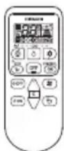
Remote controller
Send out operation signal to the indoor unit. So as to operate the whole unit.
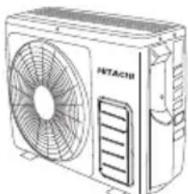
OUTDOOR UNIT
RAC-M25EAG RAC-M35EAG RAC-L10EAG RAC-L14EAG RAC-X10EAG RAC-X14EAG
Air outlet
When "heating" operation is performed, cool air blows and when "cooling" or "dehumidifying" operation is performed, warm air blows.
Drain hose
Drains the dehumidified water from the indoor unit to the outdoor during "cooling" or "dehumidifying" operation.
Piping and Wiring
Air inlets (Rear and left sides)
Drain port
text_image
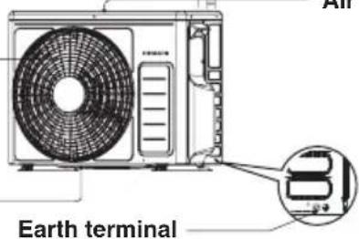
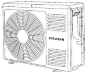
Earth terminalRAC-M50EAG RAC-X18EAG
Air outlet
When "heating" operation is performed, cool air blows and when "cooling" or "dehumidifying" operation is performed, warm air blows.
Drain hose
Drains the dehumidified water from the indoor unit to the outdoor during "cooling" or "dehumidifying" operation.
Piping and Wiring
Air inlets (Rear and left sides)
Drain port

text_image
HITACHI ort Earth terminalAbout the outdoor unit:
- When "Stop" is selected during operation of the indoor unit, the fan of the outdoor unit continues turning for 10 to 60 seconds to cool the electric parts down.
- In heating operation, condensate or water due to defrosting will flow. Do not cover the drain port of the outdoor unit because such water may freeze in the chilly area.
- When the outdoor unit is hung on the wall, install the bush and drain pipe on the drain port and drain water.
MODEL NAME AND DIMENSIONS
| MODEL | WIDTH (mm) | HEIGHT (mm) | DEPTH (mm) |
| RAS-M25/35/50EAG,L10/14EAG,X10/14/18EAG | 780 280 215 | ||
| RAC-25/35EAG,L10/14EAG,X10/14EAG | 660 530 | 8 | 27 |
| RAC-50EAG,X18EAG | 792 600 299 |
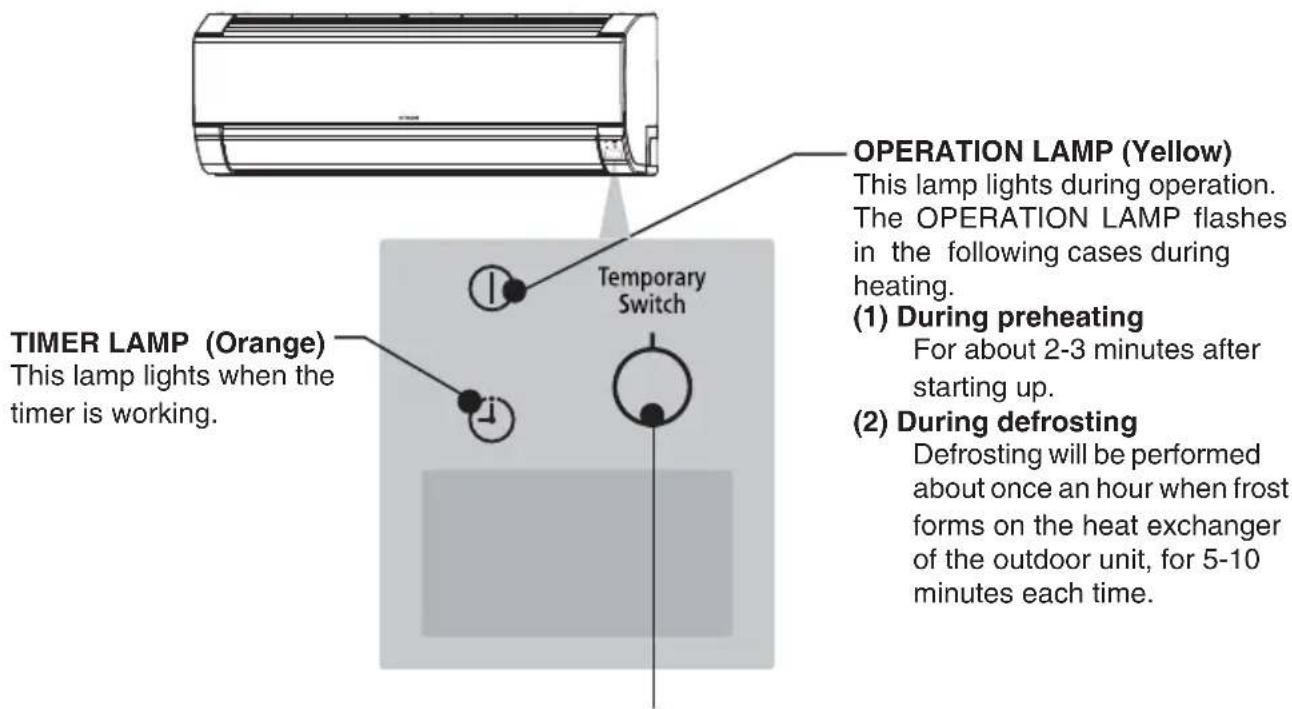
INDOOR UNIT INDICATIONS
text_image
TIMER LAMP (Orange) This lamp lights when the timer is working. Temporary Switch OPERATION LAMP (Yellow) This lamp lights during operation. The OPERATION LAMP flashes in the following cases during heating. (1) During preheating For about 2-3 minutes after starting up. (2) During defrosting Defrosting will be performed about once an hour when frost forms on the heat exchanger of the outdoor unit, for 5-10 minutes each time.TEMPORARY SWITCH

CAUTION
Turn off the circuit breaker if the unit is not be operated for a long period.
Use this switch to start and stop when the remote controller does not work.
- By pressing the temporary switch, the operation is done in automatic mode.
- When the operation is done using the temporary switch after the power source is turned off and turn on again, the operation is done in automatic mode.
☆ If the power stays on and the unit is not operated, power is slightly consumed in the control circuit. The power is saved by turning off the power switch (or the circuit breaker when the power is supplied from the outdoor unit).
This controls the operation function and timer setting of the room air conditioner. The range of control is about 7 meters. If indoor lighting is controlled electronically, the range of control may be shorter.

text_image
Signal Transmission HITACHI Transmission Sign The transmission sign blinks when a signal has been send. POWERFUL Button Press this button to start powerful operation. ( Page 4 ) TEMPERATURE Button Room temperature setting. Value will change quicker when keep pressing. ( Page 3 ) FAN SPEED Button Select the fan speed for cooling and heating mode. ( Page 3 ) AUTO SWING Button Control the angle of the horizontal air defl ector. ( Page 7 ) MODE Button Select the operation mode. ( Page 3 ) STOP Button Press this button to stop operation. ECO Button Use this button to set the ECO mode. ( Page 6 ) OFF TIMER Button Select the turn OFF time. ( Page 4 ) ON TIMER Button Select the turn ON time. ( Page 4 )Precautions for Use
- Do not put the remote controller under direct sunlight and high temperature.
- Do not drop it on the floor, and protect it from water.
- If you press the FUNCTION button during operation, the air conditioner may stop for about 3 minutes for protection before you can start it again.
■ Please use under below condition when you want to set the function mode, room temperature and fan speed manually.
| HEATING DEHUMIDIFYING COOLING | ||
| Outdoor Temperature24°C below | Room Temperature16°C above | Outdoor Temperature21°C above |
• Every time you press the button, the mode will change as the below.

: HEATING
: DEHUMIDIFYING
: COOLING
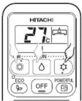
2 ROOM TEMPERATURE SETTING
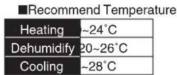
text_image
■Recommend Temperature Heating ~24°C Dehumidify 20~26°C Cooling ~28°C- The cooling operation does not start if the temperature setting is higher than the current room temperature.
3 FAN SPEED SETTING
- Every time you press the button, fan speed will change as below sequence.

text_image
HEATING COOLING } AUTO → HIGH → MED → LOW → SILENT DEHUMIDIFYING : LOW → SILENT4 Press the OFF (STOP) button
• Operation stops with a beep.
text_image
HITACHI 27°C E ECON ECO OFF POWERFUL
text_image
HITACHI 27°C ON ECO OFF POWERFUL OFF ON
text_image
HITACHI 27°C SUB......ON...... ECO OFF POWERFUL OFF ON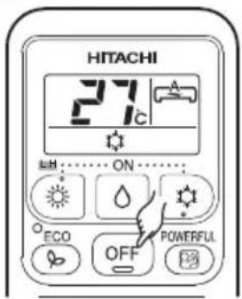
text_image
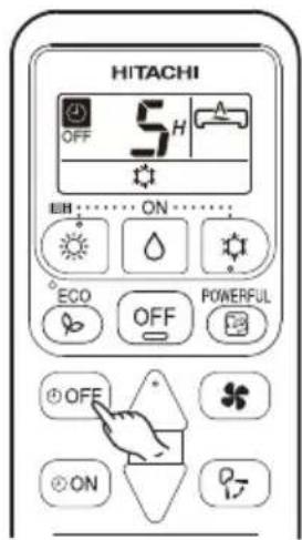
HITACHI 27°C ON ECO OFF POWERFUL■ ON Timer and OFF Timer are available.
Timer Reservation


OFF TIME setting
- Select the OFF TIME by pressing the ⏻(OFF) Button.
- Setting time will change according to the below sequence when you press the button.

flowchart
graph LR
    A["1"] --> B["2"]
    B --> C["3"]
    C --> D["..."]
    D --> E["9"]
    E --> F["10"]
    F --> G["11"]
    G --> H["12"]
    H --> I["Timer off"]
    I --> A
    style A fill:#f9f,stroke:#333
    style B fill:#f9f,stroke:#333
    style C fill:#f9f,stroke:#333
    style D fill:#f9f,stroke:#333
    style E fill:#f9f,stroke:#333
    style F fill:#f9f,stroke:#333
    style G fill:#f9f,stroke:#333
    style H fill:#f9f,stroke:#333
    style I fill:#f9f,stroke:#333
■ Operation stop at setting time
- Select the ON TIME by pressing the (ON) Button.
- Setting time will change according to the below sequence when you press the button.

flowchart
graph LR
    A["1"] --> B["2"]
    B --> C["3"]
    C --> D["..."]
    D --> E["9"]
    E --> F["10"]
    F --> G["11"]
    G --> H["12"]
    H --> I["Timer on"]
    style A fill:#f9f,stroke:#333
    style B fill:#f9f,stroke:#333
    style C fill:#f9f,stroke:#333
    style D fill:#f9f,stroke:#333
    style E fill:#f9f,stroke:#333
    style F fill:#f9f,stroke:#333
    style G fill:#f9f,stroke:#333
    style H fill:#f9f,stroke:#333
    style I fill:#f9f,stroke:#333

text_image
HITACHI ON 5H A ECHO OFF POWERFUL OFF ON P7POWERFUL OPERATION
- By pressing (POWERFUL) button during HEATING, DEHUMIDIFYING, COOLING operation, the air conditioner performs at maximum power.
- During POWERFUL operation, cooler or warmer air will be blown out from indoor unit for COOLING or HEATING operation respectively.

text_image
HITACHI 27°C ON ECO OFF POWERIL FBSTART
Press the POWERFUL (POWERFUL) button during operation.
- " [icon] " is displayed on the LCD. POWERFUL operation ends in 20 minutes. Then the system automatically operates with the previous settings used before POWERFUL operation.
CANCEL
Press the POWERFUL (POWERFUL) button again.
- " [图标] " disappears from the LCD.
NOTE
- When ECO mode, or LEAVE HOME mode is selected, POWERFUL operation is cancelled.
- During POWERFUL operation, capacity of the air conditioner will not increase
- if the air conditioner is already running at maximum capacity.
- just before defrost operation (when the air conditioner is running in HEATING operation).
• After auto restart, POWERFUL operation is cancelled and previous operation shall start.
■ Prevent the room temperature from falling too much by setting temperature at 10 deg automatically when no one is at home.

text_image
HITACHI LH A 10°C LH ONSTART
Hold down the HEATING Button for 3-5 seconds to start Leave Home operation.
• Room temperature is automatically set at 10 deg.
- "☀", "LH", "☐", "☐", is displayed on the LCD.
CANCEL
Press the (STOP) button.
Change to other Operation Mode.
NOTE
- During Leave Home operation, fan speed and horizontal air deflector position cannot be changed.
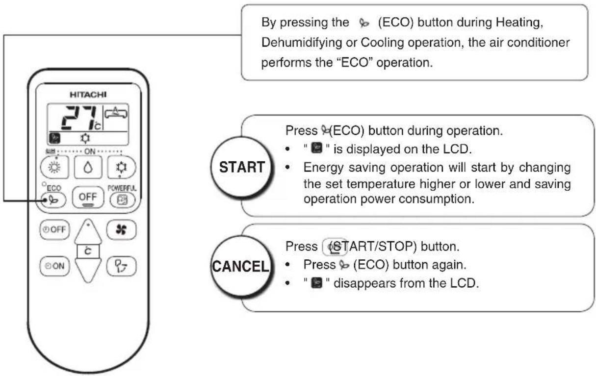
■ Energy saving operation by changing set temperature and by limiting the maximum power consumption value.
text_image
By pressing the (ECO) button during Heating, Dehumidifying or Cooling operation, the air conditioner performs the "ECO" operation. START Press (ECO) button during operation. " " is displayed on the LCD. Energy saving operation will start by changing the set temperature higher or lower and saving operation power consumption. CANCEL Press (START/STOP) button. Press (ECO) button again. " " disappears from the LCD.NOTE
- In case the power consumption is already low, ECO operation will not reduce the power consumption.
- By pressing (POWERFUL) button, ECO operation is cancelled.
• After auto restart, ECO operation is cancelled and previous operation mode shall start.

Adjust the airflow upward and downward.
According to operation, the horizontal air deflector is automatically set to the proper angle suitable for each operation. The deflector can be swings up and down and also set to the desired angle using the “(AUTO SWING)” button.

text_image
OFF ON P2- If the (AUTO SWING) " button is pressed once, the horizontal air deflector swings up and down. If the button is pressed again, the deflector stops in its current position. Several seconde (about 6 seconds) may be required before the defl ector starts to move.
- When the operation is stopped, the horizontal air deflector moves and stops at the position where the air outlet closes.

CAUTION
- In "Cooling" operation, do not keep the horizontal air deflector swinging for a long time. Some dew may form on the horizontal air deflector and some dew may drop from it.

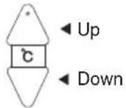
Adjust the airflow to left and right.
Hold the vertical air deflector as shown on the right and adjust the airflow to left and right.

natural_image
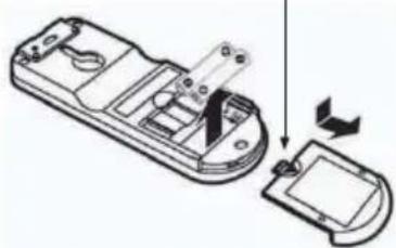
Illustration of hands installing or adjusting a wall-mounted air conditioner (no text or symbols visible)HOW TO EXCHANGE THE BATTERIES IN THE REMOTE CONTROLLER

Remove the cover as shown in the figure and take out the old batteries.


Install the new batteries.
The direction of the batteries should match the marks in the case.

CAUTION
- Do not use new and old batteries, or different kinds of batteries together.
- Take out the batteries when you do not use the remote controller for 2 or 3 months.
Push and pull to the direction of arrow
natural_image
Diagram of a remote control device with an open lid and internal components, showing a right-hand rule for change (no text or symbols present)
CAUTION
Cleaning and maintenance must be carried out only by qualified service personal. Before cleaning, stop operation and switch off the power supply.
1. AIR FILTER
Please clean the filter once about every two weeks. By doing so, the power rates are saved. In case the air filter is full of dust, the air flow will decrease and the cooling capacity will be reduced. Further, noise may occur. Be sure to clean the filter following the procedure below.
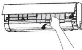
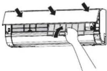
PROCEDURE

Open the front panel carefully and remove the filter.

natural_image
Technical line drawing of a cylindrical mechanical component with internal grid structure (no text or symbols)
Vacuum dust from the air filter using vacuum cleaner. If there is too much dust, wash the filter with a detergent and rinse it thoroughly. After that, dry it in the shade.
natural_image
Diagram of a hand inserting a component into an air conditioner unit (no text or symbols visible)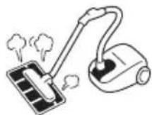

- Set the filter with "FRONT" mark facing front, and slot them into the original state.
- After attaching the filters, push the front panel at three arrow portions as shown in figure and close it.
natural_image
Diagram of a car air conditioner unit with airflow arrows indicating airflow direction (no text or labels)
CAUTION
- Do not wash with hot water at more than 40°C. The filter may shrink.
- When washing it, shake off moisture completely and dry it in the shade; do not expose it directly to the sun. The filter may shrink.
- Don't operate the unit without filter. Fault may occur if you continue.
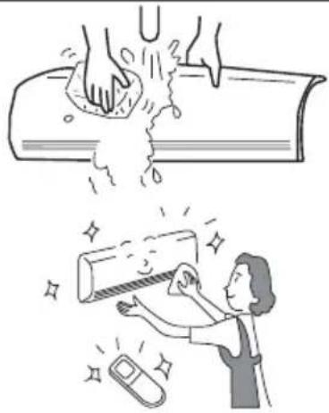
2. CLEANING OF FRONT PANEL
- Remove the front panel and wash with clean water. Wash it with a soft sponge. After using neutral detergent, wash thoroughly with clean water.
- When front panel is not removed, wipe it with a soft dry cloth. Wipe the remote controller thoroughly with a soft dry cloth.
- Wipe the water thoroughly. If water remains at indicators or signal receiver of indoor unit, it causes trouble.
Method of removing the front panel. Be sure to hold the front panel with both hands to detach and attach it.
natural_image
Illustration showing a hand washing a pipe with water splashing, and a person cleaning a tube with a phone nearby (no text or symbols)Removing the Front Panel Attaching the Front Panel

text_image
Push Arm- Push the end of the right-side arm outward to release the tab.
- Move the left-side arm outward to release the left tab, and then pull the panel towards you.

text_image
Arm- Insert the shaft of the left arm along the step on the unit into the hole.
- Securely insert the shaft of the right arm along the step on the unit into the hole.
- Make sure that the front panel is securely attached, and then close the front panel.
CAUTION
- Do not splash or direct water to the body of the unit when cleaning it as this may cause short circuit.
- Never use hot water (above 40°C), benzine, gasoline, acid, thinner or a brush, because they will damage the plastic surface and the coating.

text_image
BENIN ACID THN NERCAPABILITIES
Heating Capability
- This room air conditioner utilizes a heat pump system that absorbs exterior heat and brings it into a room to be heated. As the ambient temperature gets lower, heating capability will also lower. In such a situation, the inverter work to increase compressor rpm to keep the unit's heating capability from decreasing. If the unit's heating performance is still unsatisfactory, other heating appliances should be used to augment this unit's performance.
- The air conditioner is designed to heat an entire room so that it may take some time before you feel warm. Timer operation is recommended for effective preheating ahead of the desired time.
Do not use a stove or any other high temperature devices in proximity to the indoor unit.
Cooling and Dehumidifying Capabilities
- If the heat present in a room exceeds the unit's cooling capacity (for example, if there are many people in the room or other heating appliances are used), the preset room temperature may not be reached.
CAUTION

PROHIBITION
REGULAR INSPECTION
PLEASE CHECK THE FOLLOWING POINTS EVERY EITHER HALF YEARLY OR YEARLY. CONTACT YOUR SALES AGENT SHOULD YOU NEED ANY HELP.
| 1 |  |  | Check to see if the unit's earth line has been connected correctly.If the earth line is disconnected or faulty, unit failure or electric shock hazard may result. |
| 2 |  |  | Check to see if the mounting frame has rusted excessively or if the outdoor unit has tilted or become unstable.It could collapse or fall, causing injury. |
AFTER SALES SERVICE AND WARRANTY
WHEN ASKING FOR SERVICE, CHECK THE FOLLOWING POINTS.
| CONDITION CHECK THE FOLLOWING POINTS | |
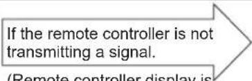 (Remote controller display is dim or blank.) (Remote controller display is dim or blank.) | Do the batteries need replacement?Is the polarity of the inserted batteries correct? |
 | Is the fuse all right?Is the voltage extremely high or low?Is the circuit breaker “ON”?Is the power plug inserted?Do you have any power cut? |
 | Is the air filter blocked with dust?Is the set temperature suitable?Have horizontal air deflectors been adjusted to their correct positions according to the operation mode selected?Are the air inlets or air outlets of indoor and outdoor units blocked?Is the fan speed “LOW”or “SILENT”? |
■ The following phenomena do not indicate unit failure.
| During heating, the operation indicator blinks and air blow stops | |
| The unit is preparing to blow warm air. Please wait. | |
| The outdoor unit is defrosting. Please wait. | |
| Hissing or fizzy sounds | Refrigerant flow noise in the pipe or valve sound generated when flow rate is adjusted. |
| Squeaking noise | Noise generated when the unit expands or contracts due to temperature changes. |
| Rustling noise | Noise generated with the indoor unit fan's rpm changing such as operation start times. |
| Clicking noise | Noise of the motorized valve when the unit is switched on. |
| Perking noise | Noise of the ventilation fan sucking in air present in the drain hose and blowing out dehumidifying water that had accumulated in the condensed water collector. For details, consult your sales agent. |
| Changing operation noise | Operation noise changes due to power variations according to room temperature changes. |
| Mist emission | Mist is generated as the air within the room is suddenly cooled by conditioned air. |
| Steam emitted from the outdoor unit | Water generated during defrosting operation evaporates and steam is emitted. |
| Odors | Caused as the smells and particles of smoke, food, cosmetics, etc. present in room air become attached the unit and blown off into the room again. |
| The outdoor unit continues to operate even if operation is stopped. | Defrosting is underway (as the heating operation is stopped, the microcomputer checks frost accumulated in the outdoor unit and instructs the unit to perform automatic defrosting if necessary). |
| The OPERATION lamp is blinking. | Shows preheating or defrosting operation is underway.As the protective circuit or preheat sensor operates when unit operation is stopped during preheating and then restarted, or when operation mode is switched from cooling to heating, the lamp continues to blink. |
| Does not reach the temperature setting | Actual room temperature may deviate slightly from the remote controller's temperature setting depending on the number of people in the room, indoor or outdoor conditions. |
- If the unit still fails to operate normally after performing the above inspections, turn the circuit breaker off and contact your sales agent immediately.
Contact your sales agent immediately if the following phenomena should occur:
- The circuit breaker switches off or the fuse blows frequently.
• The switch operation is not stable.
• Foreign matter or water accidentally enters the unit interior. - The power cord gets excessively hot or its insulation is torn or stripped.
• TIMER lamp on the indoor unit display blinks.
( As the nature of the failure can be identified by the blinking cycle, check the blinking cycle before turning off the circuit breaker. )


natural_image
Cartoon illustration of a smiling man in a suit pointing upward with both hands (no text or symbols)Notes
- In quiet operation or stopping the running, the following phenomena may occasionally occur, but they are not abnormal for the operation.
(1) Slight flowing noise of refrigerant in the refrigerating cycle.
(2) Slight rubbing noise from the fan casing which is cooled and then gradually warmed as operation stops.
- The odor will possibly be emitted from the room air conditioner because the various odor, emitted by smoke, foodstuffs, cosmetics and so on, sticks to it. So please clean the air filter and the evaporator regularly to reduce the odor.
- Please contact your sales agent immediately if the air conditioner still fails to operate normally after the above inspections. Inform your agent of the model of your unit, production number, date of installation. Please also inform him regarding the fault.
Please note:
On switching on the equipment, particularly when the room light is dimmed, a slight brightness fluctuation may occur. This is of no consequence.
The conditions of the local Power Supply Companies are to be observed.
HITACHI
RAS-L10EAG/RAC-L10EAG
RAS-L14EAG/RAC-L14EAG
RAS-X10EAG/RAC-X10EAG
RAS-X14EAG/RAC-X14EAG
RAS-X18EAG/RAC-X18EAG
natural_image
Line drawing of a Siemens HVAC air conditioner unit (no text or symbols)RAC-M25EAG
RAC-M35EAG
RAC-L10EAG
RAC-L14EAG
RAC-X10EAG
RAC-X14EAG
natural_image
Line drawing of a Hitachi air conditioner unit with fan and ventilation slots (no text or symbols on the device itself)RAC-M50EAG
RAC-X18EAG
natural_image
Line drawing of a single air conditioner unit (no text or symbols)RAS-M25EAG
RAS-M35EAG
RAS-M50EAG
RAS-L10EAG
RAS-L14EAG
RAS-X10EAG
RAS-X14EAG
RAS-X18EAG
natural_image
Technical line drawing of a cylindrical air conditioner unit with internal panel and mounting bracket (no text or symbols)
Φίλτρο αέρα
natural_image
Illustration of hands installing or adjusting a large air conditioner panel, with a magnified inset showing the blade being cut (no text or symbols present)natural_image
Diagram of a device's internal components being processed, showing a disassembly step with an arrow indicating rotation (no text or symbols present)
ΠΡΟΣΟΧΗ
natural_image
Technical line drawing of a cylindrical mechanical component with internal grid structure (no text or symbols)
natural_image
Line drawing of a hand opening a cylindrical air conditioner cover (no text or symbols)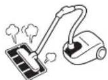

natural_image
Diagram of a car air conditioner unit with airflow arrows indicating airflow direction (no text or labels)