97-939 - Support Ergotron - Free user manual and instructions
Find the device manual for free 97-939 Ergotron in PDF.

User questions about 97-939 Ergotron
0 question about this device. Answer the ones you know or ask your own.
Ask a new question about this device
Download the instructions for your Support in PDF format for free! Find your manual 97-939 - Ergotron and take your electronic device back in hand. On this page are published all the documents necessary for the use of your device. 97-939 by Ergotron.
USER MANUAL 97-939 Ergotron
Ethernet Channel Upgrade Kit
for Zip40 Charging Cart
natural_image
Illustration of a multi-level electronic device with battery packs inside, showing hand inserting a cable (no text or symbols)Components

| ABCDEE | ||||||
| 1 | 9x | 4x 4x M5 x 10mmM4 x 15mm M5 x 10mmM4 x 15mm |  M5 M4 M5 M4 |  |  |  |
| 2 | 2x15x | 1x10x | ||||
Tools Needed


7mm 8mm
For the latest User Installation Guide please visit: www.ergotron.com

User's Guide - English
Hazard Symbols Review
These symbols alert users of a safety condition that demands attention. All users should be able to recognize and understand the significance of the following Safety Hazards if encountered on the product or within the documentation. Children who are not able to recognize and respond appropriately to Safety Alerts should not use this product without adult supervision!
| Symbol | Signal Word | Level of Hazard |
 | NOTE | A NOTE indicates important information that helps you make better use of this product. |
 | CAUTION | A CAUTION indicates either potential damage to hardware or loss of data and tells you how to avoid the problem. |
 | WARNING | A WARNING indicates either potential for property damage, personal injury, or death. |
 | ELECTRICAL | An Electrical indicates an impending electrical hazard which, if not avoided, may result in personal injury, fire and/or death. |
Safety

Warning: Unplug power cable from outlet and make sure power button is turned off before removing side cover. Removing side cover with power on may cause equipment damage and/or serious personal injury.

text_image
Diagram illustrating the installation of a power supply unit with open circuit switches and power protection symbols.WARNING
MOVING PARTS CAN CRUSH AND CUT
Unplug power cord. DO NOT place hands on or near fans. Placing hands on or near fans may cause equipment damage and/or serious personal injury.


WARNING: MOVING PARTS CAN CRUSH AND CUT. Unplug power cord. DO NOT place hands on or near fans. Placing hands on or near fans may cause equipment damage and/or serious personal injury.
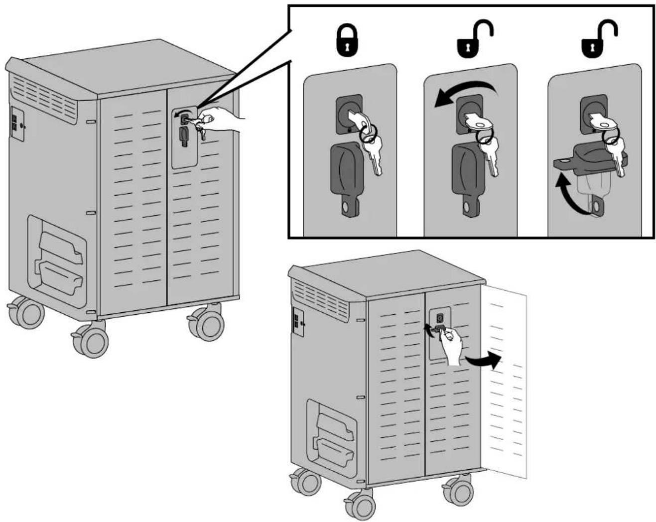
1
Open doors.
text_image
Diagram illustrating the step-by-step installation of a lock mechanism on an industrial machine, showing key locking and lock switch states.2
Unplug power cable from cart and remove side cover.
WARNING
MOVING PARTS CAN CRUSH AND CUT
Unplug power cord.
DO NOT place hands on or near fans. Placing hands on or near fans may cause equipment damage and/or serious personal injury.


WARNING: MOVING PARTS CAN CRUSH AND CUT. Unplug power cord. DO NOT place hands on or near fans. Placing hands on or ans may cause equipment damage and/or serious personal injury.

text_image
Diagram showing three steps of a server rack unit with labeled components and directional arrows indicating assembly or operation.888-97-388-G-00 rev. B · 08/15
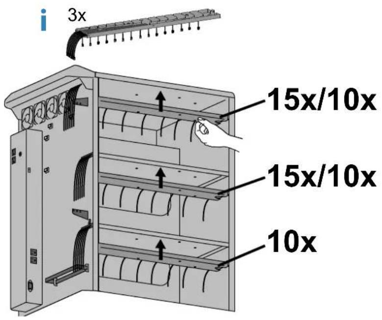
3 Choose configuration for number of devices.
40x
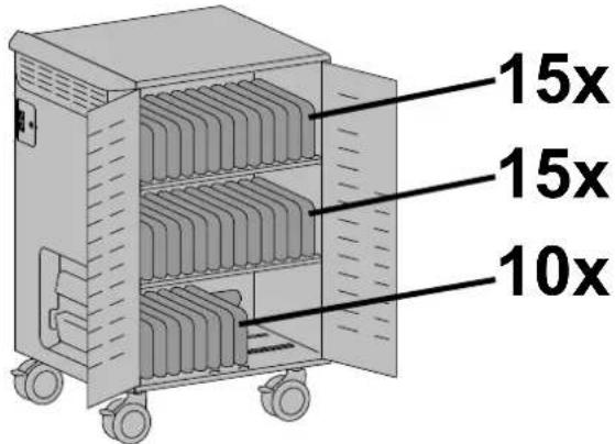
text_image
15x 15x 10xFor 40 device configuration, skip to step 5.
30x
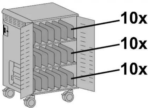
text_image
10x 10x 10xTo configure for 30 devices, remove 5 cables from each of the 2 trays with 15 cables.
i. Remove cable clips.
ii. Remove Ethernet cables in rows 2, 5, 8, 11, 14 and keep or route cables in rows 1*, 3*, 4*, 6*, 7*, 9*, 10*, 12*, 13*, 15*.
iii. Reattach cable clips.
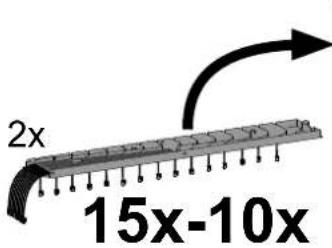
text_image
2x 15x-10x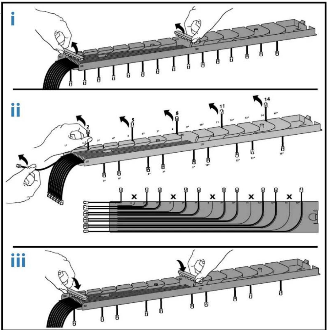
text_image
Technical diagram illustrating three sequential steps of a cable or connector assembly, labeled i, ii, and iii.4 Route ethernet cables through side channels and attach cable trays.
text_image
3x 15x/10x 15x/10x 10x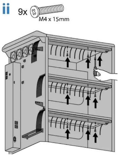
text_image
9x M4 x 15mm5 Route ethernet cable through 'P' clips and attach clips to cart.
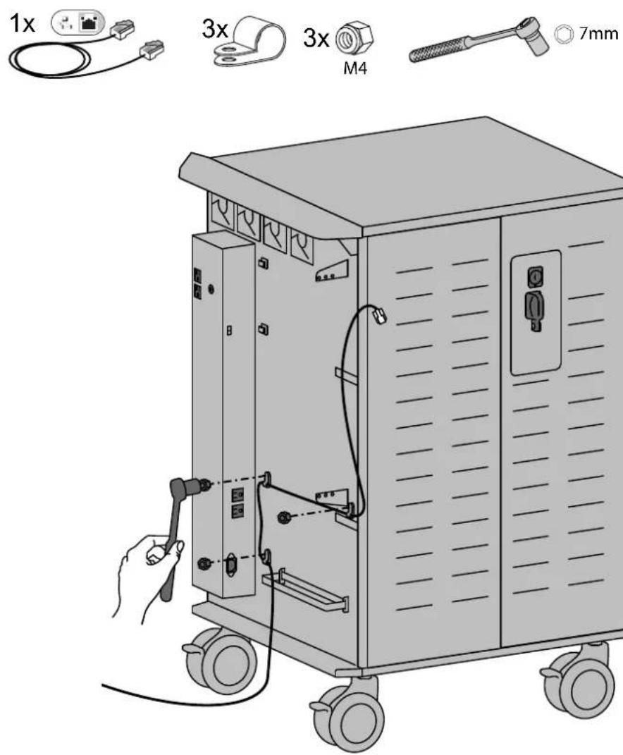
text_image
1x 3x 3x M4 7mm
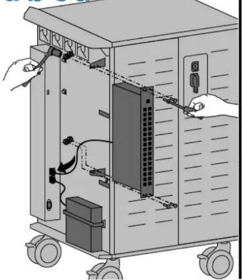
Switch installation (not included).
Max Dimensions of Switch
(Must meet 1U Rack Mount Standard)
17.5"W x 12.4"H x 1.8"D (44x26x4.4 cm)
Ethernet switch attachment:
a. Attach unit to cart.
b. Plug in external Ethernet cable and WAP Ethernet cable to switch.
c. Plug in Ethernet cables from devices.
d. Store excess cables between switch and cart.
e. Follow manufacturers instructions for WAP and Switch set up.
4x

4x

M5
C
8mm
a
bcd
natural_image
Illustration of a server rack with hands connecting to a panel, showing internal components and wiring (no text or symbols)
natural_image
Diagram of an electronic device showing a rack-mounted panel connected to a control panel, with no visible text or symbols.
natural_image
Illustration of an electronic device with a hand connecting cables to a rack-mounted panel (no text or symbols visible)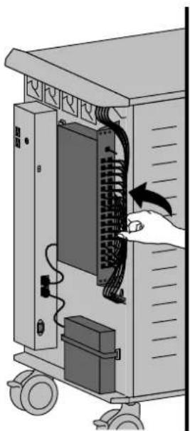
natural_image
Illustration of a server rack with an open panel and cable, showing a hand inserting a cable into the rack (no text or symbols visible)
Attach side cover and plug power cable back into cart.
NOTE: Route external Ethernet cable through side cover access door.
a
2
text_image
Diagram showing server rack with labeled components and connection to a device, including a close-up of the cable being inserted.b

natural_image
Technical line drawing of a multi-level industrial machine with wheels and internal compartments (no text or symbols)
natural_image
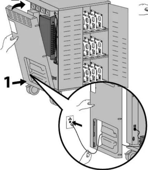
Illustration of hands connecting a device to a wall-mounted unit with cable (no text or symbols visible)8
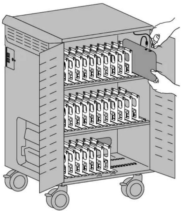
Plug in and insert devices.

natural_image
Illustration of a multi-level electronic device with battery modules and a hand inserting a switch (no text or symbols)9
Plug in power and Ethernet cables and turn cart power on.

text_image
Diagram showing two electrical device setups with power and protection symbols, one connected to a plug and the other to a switch.Americas Sales and
Corporate Headquarters EMEA Sales
1181 Trapp Rd.
St. Paul, MN USA
(800) 888-8458
+1-651-681-7600
www.ergotron.com
sales@ergotron.com
APAC Sales
Tokyo, Japan
www.ergotron.com
apaccustomerservice@ergotron.com
Worldwide OEM Sales
www.ergotron.com
info.oem@ergotron.com
ERGOTRON®
While Ergotron, Inc. makes every effort to provide accurate and complete information on the installation and use of its products, it will not be held liable for any editorial errors or omissions (including those made in the process of translation from English to another language), or for incidental special or consequential damages of any nature resulting from furnishing this instruction and performance of equipment in connection with this instruction. Ergotron, Inc. reserves the right to make changes in the product design and/or product documentation without notification to its users. For the most current product information, or to know if this document is available in languages other than those herein, please contact Ergotron. No part of this publication may be reproduced, stored in a retrieval system, or transmitted in any form or by any means, electronic, mechanical, photocopying, recording or otherwise without the prior written consent of Ergotron, Inc.,1181 Trapp Road, Eagan, Minnesota, 55121, USA Patents Pending and Patented U.S. & Foreign. Ergotron is a registered trademark of Ergotron, Inc.
© 2015 Ergotron, Inc. All rights reserved.