FCS-9436 - Logiciel de photo/vidéo LEVELONE - Free user manual and instructions
Find the device manual for free FCS-9436 LEVELONE in PDF.

User questions about FCS-9436 LEVELONE
0 question about this device. Answer the ones you know or ask your own.
Ask a new question about this device
Download the instructions for your Logiciel de photo/vidéo in PDF format for free! Find your manual FCS-9436 - LEVELONE and take your electronic device back in hand. On this page are published all the documents necessary for the use of your device. FCS-9436 by LEVELONE.
USER MANUAL FCS-9436 LEVELONE
Copyright (c) 2011 Digital Data Communications Co., Ltd.
All Rights Reserved.
All features and functions are subject to change without notice. Please visit www.level1.com for the latest ones.
TABLE OF CONTENTS
LevelOne IP CamSecure
TABLE OF CONTENTS .... 1
INSTALLATION 6
Minimum System Requirement 6
Install IP camera(s)....7
Install capture card(s) 7
INSTALLATION 8
IP CamSecure Installation 9
Remote Desktop Tool....12
DVR Driver Installation 15
PDA Client Installation....17
Smart Phone Client Installation 18
iPhone Client Installation 19
Quick Start 23
Execute Main Console 23
Activate IP Camera License(s) 23
Install IP camera(s) 24
Add IP camera(s) 24
Set Schedule 25
Set Smart Guard 25
Start Recording & Smart Guard 26
Playback....26
1. MAIN CONSOLE....27
1.1 User Interface Overview 28
1.2 PTZ Camera Control 30
1.2.1 Set Preset Point / Go to Preset Point 30
1.2.2 Zoom....30
1.2.3 Focus 30
1.2.4 Patrol 30
1.3 On Screen Menu....31
1.3.1 Enable Move/Area Zoom....31
1.3.2 Enable Talk 31
1.3.3 Enable Digital PTZ 31
1.3.4 ImmerVision Lens Setting 31
1.3.5 Connect/ Disconnect 31
1.3.6 Show Camera....31
1.3.7 Duplicate Camera....31
1.3.8 Delete Camera 31
1.3.9 Enable Digital PTZ 31
1.3.10 Fix Aspect Ratio 32
1.3.11 Instant Playback....32
1.3.12 Snapshot 32
1.3.13 Manual Record 32
1.3.14 Toggle Full screen 32
1.4 Live Display....32
1.5 Instant Playback 33
1.5.1 Instant Playback window overview....33
1.5.2 The navigation of Instant Playback 33
2. PLAYBACK 35
2.1 User Interface overview: 36
2.2 Open Record / Date Time Search Dialog 38
2.2.1 Date Time Panel 38
2.2.2 Record Display Window....38
2.2.3 Date Time Period....38
LevelOne IP CamSecure
2.2.4 Video Preview 38
2.2.5 Event Type 38
2.2.6 Time Table....39
2.2.7 Withdraw the Record 39
2.3 Search Mode 40
2.3.1 Unusual Event-General Motion 40
2.3.2 Unusual Event-Foreign Object 40
2.3.3 Unusual Event-Missing Object....41
2.3.4 Unusual Event- Focus Lost / Camera Occlusion 41
2.4 Enhancement / Post Processing Tool....41
2.4.1 General Setting 41
2.4.2 Filter Setting 41
2.5 Save Video 41
2.6 Save Image....42
2.7 Print 43
2.8 Backup 43
2.9 Log Viewer 44
2.9.1 Unusual Event......44
2.9.2 Export and Backup Log 45
2.9.3 System Log 45
2.9.4 Counting Application.... 46
2.9.5 Counting Application (Diagram) 47
2.9.6 POS Log 47
2.9.7 Export and Backup Log 48
2.9.8 Export 48
2.10 Setting 49
2.11 Remote Server 50
2.11.1 Add Remote Playback Site 50
2.11.2 Access Remote Playback Site 50
3. SCHEDULE....51
3.1 Day / week Mode 52
3.1.1 Load Preset Modes 52
3.1.2 Insert a New Schedule Manually 54
3.1.3 Copy Schedule....54
3.1.4 Holiday and Custom setting 54
3.2 Adjust the Scheduled Setting: 55
3.3 Encoding Option 56
3.3.1 Pre-record/ Post-record Time 56
3.3.2 Record Mode 56
3.3.3 Encoded Options....56
4. GUARD....58
4.1 Event 59
4.1.1 Camera Event - Assign a Camera Event 59
4.1.2 Camera Event – Basic Setting 59
4.1.3 Camera Event - Signal Lost 60
4.1.4 Camera Event - General Motion 60
4.1.5 Camera Event - General Motion (Device) 60
4.1.6 Camera Event - Foreign Object....61
4.1.7 Camera Event - Missing Object 61
4.1.8 Camera Event - Lose Focus 62
4.1.9 Camera Event - Camera Occlusion 63
4.1.10 POS Event - Assign a POS Event 63
4.1.11 Digital Input Event - Digital Input Event 64
4.1.12 System Event - Assign a System Event 64
4.1.13 System Event - Disk Space Exhausted 65
4.1.14 System Event - System Health Unusual....65
4.1.15 System Event – Resource Depleted 65
LevelOne IP CamSecure
4.1.16 System Event – Network Congestion.... 65
4.1.17 System Event – TV-Out 65
4.2 Action....66
4.2.1 Action - Assign a action type 66
4.2.2 Action Type - On Screen display....66
4.2.3 Action Type - Play Sound 66
4.2.4 Action Type - Send E-mail 67
4.2.5 Action Type - Phone Call 67
4.2.6 Action Type - PTZ Preset Go 67
4.2.7 Action Type - DI/DO 68
4.2.8 Action Type –Send an SMS message 68
4.2.9 Action Type – Send to Central Server 68
4.2.10 Action Type – Send snapshot to FTP 69
4.2.11 Action Type – Popup E-Map on Event....69
4.3 Advanced Settings 69
5. CONFIGURATION....70
5.1 Setting – General 71
5.1.1 Startup 71
5.1.2 Storage....71
Miscellaneous 71
Status Display 71
Storage....71
Startup 71
Auto Reboot 71
Audio Preview....71
5.1.3 Status Display 72
5.1.4 Miscellaneous 73
5.1.5 Audio Preview 73
5.1.6 Auto Reboot 74
5.2 Setting - Camera 75
5.2.1 Add Camera....75
5.2.2 IP Camera / Video Server Setting panel 76
5.2.3 Camera Parameter 76
5.2.4 OSD Setting 77
5.3 Setting - I/O Device 78
5.4 Setting - PTZ Config....78
5.5 Setting – Hotline....80
5.6 Setting - Address Book 81
5.7 Setting – Monitor Display 81
5.8 Setting – Joystick 82
5.9 User Account Setting 83
5.10 License Manager 84
5.11 Save/ Load Configuration 84
5.12 Counting Application 85
5.13 POS Application 85
5.14 Network Service 86
5.14.1 Live Streaming Server 86
5.14.2 Remote Playback Server 88
5.14.3 3GPP Service....89
5.14.4 Remote Desktop 90
5.14.5 Central Management Service 90
5.15 About Main Console 91
5.16 Video Source 91
6. E-MAP 92
6.1 Edit Mode 93
6.1.1 Add/Edit/Delete Map 93
6.1.2 Add/Rotate/Delete Device Indicator 94
LevelOne IP CamSecure
6.2 Operate Mode 94
6.2.1 Device and Map Tree list....94
6.2.2 E-Map picture 95
6.2.3 Information and Preview windows 95
6.3 Layout Adjustment 95
- LOG VIEWER....96
7.1 Unusual Event 97
7.2 System Log 98
7.3 Counting Application 99
7.4 Counting Application (Diagram) 100
7.5 POS Log 100
7.6 Export 101
- BACKUP 102
8.1 Backup Recorded files 103
8.2 Delete Recorded files 104
- REMOTE LIVE VIEWER 105
9.1 Setting 106
9.1.1 General Setting 106
9.1.2 Server setting.... 106
9.1.3 Group Setting....107
9.1.4 Camera Setting 107
9.1.5 OSD Setting 108
9.1.6 POS Setting 108
9.1.7 Monitor Display Setting 109
9.1.8 Notification Setting 109
9.1.9 Joystick Setting 110
9.2 Server/Group/Camera 110
9.2.1 login/logout server....111
9.2.2 Connect/Disconnect camera 111
9.2.3 Multiple Views: 111
9.3 PTZ Control 111
9.3.1 Preset/ Go 111
9.3.2 Zoom....112
9.3.3 Focus 112
9.3.4 Patrol 112
9.4 On Screen Menu....112
9.4.1 Enable Move / Area Zoom....112
9.4.2 Enable Talk 112
9.4.3 Enable Digital PTZ 112
9.4.4 ImmerVision Lens Setting 112
9.4.5 Stream Profile 112
9.4.6 Instant Playback....112
9.4.7 Enable Audio 113
9.4.8 Snapshot 113
9.4.9 Toggle Full screen....113
9.5 Start Monitor....113
9.5.1 Multiple Monitor....113
9.5.2 E-Map 113
9.5.3 I/O Control....114
9.6 Playback....114
9.6.1 Add Remote Playback Site....114
9.6.2 Access Remote Playback Site 114
- WEB VIEW....115
10.1 Server IP 115
10.2 Remote Live Viewer 115
10.3 Remote Playback....115
LevelOne IP CamSecure
10.4 Download Client Pack 115
11. UTILITIES....116
A. Verification Tool....117
1.1 Execute Verification Tool 117
1.2 Verification Tool Overview 117
1.3 Verify Image/Video 118
B. License Management Tool 119
1.1 License Management Tool Overview 119
1.2 Activate/Transfer License 120
C. Resource Management Tool 123
1.1 Execute Resource Management tool....123
1.2 System Resource Overview....123
1.3 Advanced Resource Report 124
D. DB Tool....126
1.1 Repair Database....126
1.2 Export Configurations....129
APPENDIX A - 3GPP SERVICE 130
1.1 Configuration from Main Console server 130
1.2 Configuration from 3G Mobile Phone ....131
1.2.1 BenQ-Siemens E81 131
1.2.2 BenQ P50 132
APPENDIX B – PDA / SMART PHONE CLIENT....133
1.1 Install PDA / Smart Phone Client 133
1.2 Execute PDA / Smart Phone Client 133
1.2.1 Main Console setting....133
1.2.2 Execute and Login.... 134
1.3 PDA/Smart Phone Client Overview.... 134
1.3.1 Live View....134
1.3.2 I/O Control....136
1.3.3 System Info 136
APPENDIX C – IPHONE BROWSER 137
1.1 Configuration from Main Console server 137
1.2 Connect to Main Console server 137
1.3 Live Display....137
1.4 PTZ Control 137
APPENDIX D - REMOTE DESKTOP TOOL....138
APPENDIX E - IPHONE APP "ICAMSECURE" 139
APPENDIX F - DEVICE PACK....140
Installation
Minimum System Requirement
| Total FPS at CIF | 2200~1400 | 1400~1050 | 1050~550 | 550~ |
| CPU | Intel Core I7 | Intel Core I5 | Intel Core 2 Quad Q9400 | Intel Core 2 Duo E5300 |
| RAM | 2GB | 2GB | 2GB | 1GB |
| Motherboard | Intel 55 or 57 chip or above, MB vendor Asus, Gigabyte or Intel with Intel Chipset recommended | Intel 35 or 33 chip or above, MB vendor Asus, Gigabyte or Intel with Intel Chipset recommended | ||
| Display | ATI Radeon 4650 , nVIDIA GeForce GF-9600 or above (ATI recommended) | |||
| Ethernet | 100 baseT or above, Gigabit LAN recommended | |||
| Hard | 250 GB or above | |||
| OS | MS Windows XP pro SP3 / Vista SP1/ Win 7 | |||
Parameter definition: For IP network camera
S= M*N
M: parameter of resolution of IP camera
N: FPS of Camera
| Resolution | 5M | 3M | 2M | 1M | VGA/D1 | CIF |
| Value of M | 37 | 27 | 22 | 14 | 3 | 1 |
For example: 8 channels system
a) 1 camera at 1 Mega-pixel resolution with 10FPS
b) 2 cameras at D1 resolution with 15FPS
c) 5 cameras at CIF resolution with 30FPS
Answer:
a) M=14; N=10, S=14*10=140. b) M=3; N=15, S=3*15=45 c) M=1; N=30, S=1*30=30
S of All Cam. = 1*140+2*45+5*30=380
Therefore, the Minimum Hardware Requirement is A level.
Parameter definition: For Capture card
S=M^*N+P
P: parameter of capture card
For FCS-8004: P = 60, FCS-8005v1: P = 60, FCS-8006: P = 120
For example: 16 channel system
a) 1 camera at 1 Mega-pixel resolution with 10FPS
b) 2 cameras at D1 resolution with 15FPS
c) 5 cameras at CIF resolution with 30FPS
d) 8 cameras with 2pcs FCS-8006
a) M=14; N=10, S=14*10=140 b) M=3; N=15, S=3*15=45
c) M=1; N=30, S=1*30=30 d) P=120
S of All Cam.=1*140+2*45+5*30+2*120=620
Therefore, the Minimum Hardware Requirement is B level.
LevelOne IP CamSecure
Install IP camera(s)
Step 1: Set up the IP camera referring to the quick installation guide provided.
Step 2: Check the network between the IP camera and the system.
Step 3: Add the IP camera to the system. See details on later pages.
Install capture card(s)
Step1: Insert the card onto an empty PCI slot. Connect the Audio/Video Cable to the connector in the same color.
Step 2: Turn on your PC and start Windows.
Step 3: Insert the included Software CD into CD-ROM.
Step 4: Run SetupDrv.exe from the CD-ROM driver/ directory to install the Capture Card driver.
Step 5: Run dxdiag.exe from start menu 'Start->Run' to check your DirectX version. If the installed version is less than 9.0, install DirectX 9.0 from the CD-ROM directx9/ directory.
Step 6: After driver being installed, restart your PC.
INSTALLATION
LevelOne IP CamSecure
The Installation CD contains the software you need to run the complete system. If you are installing the system on multiple PCs, install the appropriate software for each PC:

text_image
LevelOne Network Camera LevelOne Network Camera Install Software QiG User Manual Install Adobe Reader Explore the CD Exit LevelOne Network Camera LevelOne Network Camera Device Search IP CamSecure (64CH) IP CamSecure Pro (trial) Back Copyright © 2011 Digital Data Communications Co. Ltd. All rights reserved. LevelOne level One level One level One level One level One level One level One level One level One level One level One level One level One level One level One level One level One level One level One level One level One level One level One level One level One level One level One level One level One level One level One level One level One level One- Server Application: All functions of IP CamSecure systems including MainConsole, Playback, Remote Live Viewer, Backup, and Verification Tool.
- Remote Desktop Tool: The tool to access main console and setup configuration remotely.
- PDA Client: Client application in PDA device.
- Smart Phone Client: Client application in smart phone device.
- iPhone Client: Client application in iPhone, iPod touch, and iPad. Requires iOS 3.0 or later
The following section describes the installation of each element of the Intelligent Surveillance System.
IP CamSecure Installation
Step 1: Insert the Installation CD. Run autorun.exe from the CD-ROM directly to start the installation.

text_image
LevelOne Network Camera LevelOne Network Camera Install Software QIG User Manual Install Adobe Reader Explore the CD Exit LevelOne Network Camera LevelOne Network Camera Device Search IP CamSecure (64CH) IP CamSecure Pro (trial) Back Copyright © 2011 Digital Data Communications Co., Ltd. All Rights Reserved.Step 2: The setup page should be loaded automatically. If it does not, please select your CD-ROM drive manually to open the setup page. Click "IP CamSecure" to initiate the installation.
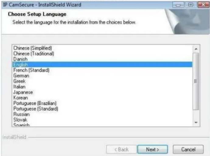
Step 3: Select the language for installation from the choices below
text_image
IP CamSecure - InstallShield Wizard Choose Setup Language Select the language for the installation from the choices below. Chinese (Simplified) Chinese (Traditional) Danish English French (Standard) German Greek Italian Japanese Korean Portuguese (Brazilian) Portuguese (Standard) Russian Slovak Spanish InstallShield < Back Next > CancelNote: if you want to install Farsi or Hebrew, please select English for language.
After installation is finished, run LangPackFAR.exe for Farsi or LangPackHEB.exe for Hebrew from the language pack folder in CD-ROM directory to install.
LevelOne IP CamSecure
Step 4: Select Next to continue.

text_image
IP CamSecure - InstallShield Wizard Welcome to the InstallShield Wizard for IP CamSecure The InstallShield® Wizard will install IP CamSecure on your computer. To continue, click Next. (Back Next) CancelStep 5: Check the option I accept the terms of the license agreement, select Next to continue.

text_image
IP CamSecure - InstallShield Wizard License Agreement Please read the following license agreement carefully End User License Agreement ("EULA") Do not install or use the software until you have read and accepted all of the license terms. Permission to use the software is conditional upon your agreeing to the license terms, installation or use of the software by you will be deemed to be acceptance of the license terms. Acceptance will bind you to the license terms in a legally enforceable contract with Digital Data Communications Asia Co. Ltd. * SOFTWARE LICENSE AND LIMITED WARRANTY This is an agreement between you, the end user, and Digital Data Communications Asia Co. Ltd. ("DOCA"). By using this software, you agree to become bound by the terms of this agreement. ● I accept the terms of the license agreement ○ I do not accept the terms of the license agreement Print < Back Next > CancelStep 6: Enter the appropriate information, select Next to continue.
text_image
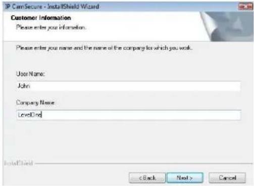
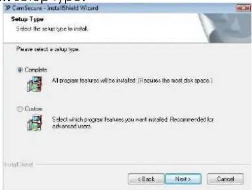
IP CamSecure - InstallShield Wizard Customer Information Please enter your information. Please enter your name and the name of the company for which you work. User Name: John Company Name: LevelDnd InstallShield < Back Next > CancelStep 7: Choose Complete or Custom setup type.
text_image
IP CamSecure - InstallShield Wizard Setup Type Select the setup type to install. Please select a setup type. @ Complete All program features will be installed (if requires the most disk space.) Custom Select which program features you want installed. Recommended for advanced users. InstallShield < Back Next > CancelCOMPLETE SETUP TYPE
LevelOne IP CamSecure
Installs all program features into the default directory.
Check Complete, and then select Next. All program features will be installed. [COMPLETE SETUP requires the most disk space.]
CUSTOM SETUP TYPE
Allows you to install the system to a preferred directory and select whichever program feature(s) to install. [Recommended for advanced users]
Check Custom, and then select Next.
Select Change if you wish to modify the installation directory.
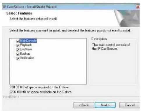
Select the feature(s) for setup to install, select Next.
text_image
IP CamSecure - InstallShield Wizard Select Features Select the features: setup will install. Select the features: you want to install, and deselect the features: you do not want to install. ✓ Scan Console ✓ Playback ✓ Unlock ✓ Backup ✓ Verification Description The main control console of the IP CamSecure. 220.83 MB of space required on the C drive 2237.00 MB of space available on the C drive < Back Next > Cancel
text_image
IP CamSecure - InstallShield Wizard Choose Destination Location Select folder where setup All install files. Install IP CamSecure to C:\Program Files\LevelOne\MP\CamSecure Change... InstallShield < Back Next > CancelStep 8: Select Install to start the installation.
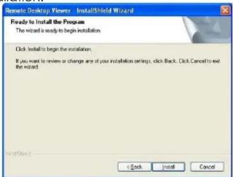
text_image
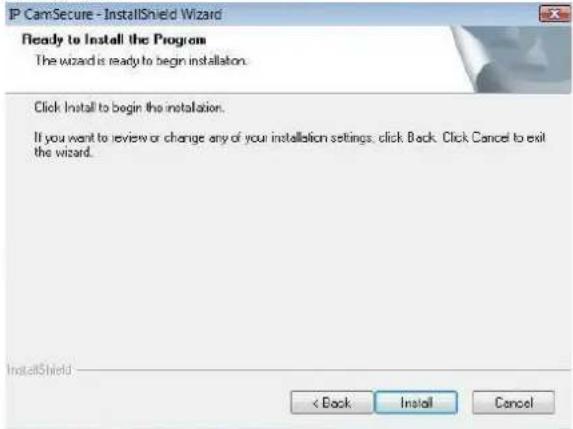
P CamSecure - InstallShield Wizard Ready to Install the Program The wizard is ready to begin installation. Click Install to begin the installation. If you want to review or change any of your installation settings, click Back. Click Cancel to exit the wizard. InstallShield < Back Install CancelStep 9: Select Finish, installation complete.

text_image
IP CamSecure - InstallShield Wizard InstallShield Wizard Complete The InstallShield Wizard has successfully installed IP CamSecure. Click Finish to exit the wizard < Back Finish CancelLevelOne IP CamSecure
Remote Desktop Tool
Remote Desktop Tool allow user remote to access Main Console System and setup configuration.
Step 1: Insert the Installation CD. Run autorun.exe from the CD-ROM directly (LevelOne-Pro-1.xx.x/RemoteDesktopViewer) to start the installation.
Step 2: Select Remote Desktop Tool.
Step 3: In the InstallShield Wizard dialog box, click Next to continuous.

text_image
Remote Desktop Viewer - InstallShield Wizard Welcome to the InstallShield Wizard for Remote Desktop Viewer The InstallShield Wizard will install Remote Desktop Viewer on your computer. To continue, click Next OK Next CancelStep 4: Check the option I accept the terms of the license agreement. Select Next.
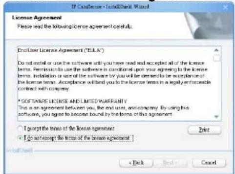
text_image
IP Customer - TotalBank Wizard License Agreement Please read the following license agreement carefully. End User License Agreement ("EULA") Do install or use the software until you have read and accepted all of the license terms. Permission to use the software is conditional upon your agreeing to the license terms. Installation or use of the software by you will be deemed to be acceptance of the license terms. Acceptance will bind you to the license terms in a legally enforceable contract with company. * SOFTWARE LICENSE AND LIMITED WARRANTY This is an agreement between you, the end user, and company. By using this software, you agree to become bound by the terms of this agreement. I accept the terms of the license agreement. I do not accept the terms of the license agreement. Print < Back Next > CancelStep 5: Enter your information, select Next.

text_image
IP Consensus - InstalShield Wizard Customer Information Please enter your information. Please enter your name and the name of the company for which you make. User Name: Test User Company Name: Test Computer < Back Next > CancelLevelOne IP CamSecure
Step 6: Select Complete or Custom setup type.
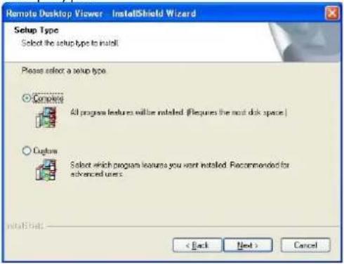
text_image
Remote Desktop Viewer - InstallShield Wizard Setup Type Select the setup type to install Please select a setup type Complete All program features will be installed. (Requires the most disk space) Capture Select which program features you want installed. Recommended for advanced users. < Back Next > CancelCOMPLETE SETUP TYPE
Install all program features into the default directory.
Check Complete, and then select Next. All program features will be installed. [Requires the most disk space.]
CUSTOM SETUP TYPE
Install the system to a preferred directory. Select program feature(s) to install. [Recommended for advanced users]
Check the option Custom, select Next.
Select Change to select folder setup will install files.
Select the features setup will install.
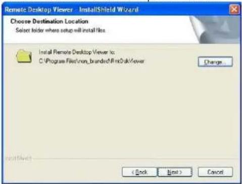
text_image
Remote Desktop Viewer - InstallShield Wizard Choose Destination Location Select folder where setup will install files. Install Remote Desktop Viewer to: C:\Program Files\non_branded\FindDak\ viewer Change... < Back Next > Cancel
text_image
Remote Desktop Viewer - InstallShield Wizard Select Features Select the features setup will install. Select the features you want to install, and do select the features you do not want to install. ✓ Remote Desktop Viewers Description 3.01 MB of space required on the C drive 3368.95 MB of space available on the C drive < Back Next > CancelStep 7: Select Install to start the installation.
text_image
Remote Desktop Viewer - InstallShield Wizard Ready to Install the Program The wizard is ready to begin installation. Click install to begin the installation. If you want to review or change any of your installation settings, click Back. Click Cancel to exit the wizard. < Back Install CancelLevelOne IP CamSecure
Step 8: Select Finish after installing the system completely.

text_image
Remote Desktop Viewer - InstallShield Wizard InstallShield Wizard Complete The InstallShield Wizard has successfully installed Remote Desktop Viewer. Click Finish to exit the wizard.DVR Driver Installation
Driver Install Tool help user to auto detect type of capture card and install corresponding drivers. Step 1: Insert the Installation CD. Run InstallDri.exe from the CD-ROM directly to start the installation. Step 2: In the Driver Setup dialog box, select Next. text_image
CaptureCardDrivers Setup Welcome to the CaptureCardDrivers Setup Wizard This wizard will guide you through the installation of CaptureCardDrivers. It is recommended that you does all other applications before starting Setup. This will make it possible to update relevant system files without having to reboot your computer. Click Install to start the installation. Install Canceltext_image
CaptureCardDrivers Setup License Agreement Please review the license terms before installing CaptureCardDrivers Press Page Down to see the rest of the agreement. End User License Agreement ("EULA") Do not install or use the software until you have read and accepted all of the license terms. Permission to use the software to conditional use your agreeing to the license terms. Installation or use of the software by you will be deemed to be accordance of the license terms. Acceptance will bind you to the license terms in a legally enforceable contract with company. * SOFTWARE LICENSE AND LIMITED WARRANTY This is an agreement between you, the end user, and company. By using this software, If you accept the terms of the agreement, click I Agree to continue. You must accept the agreement to install NULUDriver. < Back 1 Agree Canceltext_image
CaptureCardDrivers Setup Installing Please wait while CaptureCardDrivers is being installed. Execute: "DetectCardUsers" PCIWEIR_19996DEV_A800 Show details < Back Next > Canceltext_image
CaptureCardDrivers Setup Completing the CaptureCardDrivers Wizard Your computer must be restarted in order to complete the installation. Do you want to reboot now? ● Reboot now! ○ I want to manually reboot later s Back Finish CancelPDA Client Installation
Step 1: Connect PDA device to the PC. Step 2: Insert the installation CD, click PDA Client Installation from the CD-ROM directly (LevelOne-Pro-1.xx.x/PDA\_Client) to automatically install the client application in device. Note: If you do not have Microsoft® ActiveSync installed, a message will appear "Cannot find ActiveSync, install ActiveSync and run installation again". Step 3: Check that the client application is installed completely in PDA device. text_image
PDA Client.CAB was successfully installed on your device. If you need more storage space, you can remove installed programs.Smart Phone Client Installation
Step 1: Connect Smart Phone device to the PC. Step 2: Insert the installation CD, click Smart Phone Client Installation from the CD-ROM directly (LevelOne-Pro-1.xx.x /SP\_Client) to automatically install the client application in device. Note: If you do not have Microsoft® ActiveSync installed, a message will appear "Cannot find ActiveSync. Please reinstall ActiveSync and then run this installation again." Step 3: Check the client application is installed completely in smart phone device. text_image
Installation successfully installed on your device. If you need more storage space, you can remove installed programs. DoneiPhone Client Installation
Requirements: Compatible with iPhone, iPod touch, and iPad. Requires iOS 3.0 or laterMain console
Step 1: To see live view on your iPhone, you must enable live streaming service in main console.1.) Go to network services
text_image
Setting User Account Setting License Manager Save/Load Configuration Video Source Counting Application POS Application Log Viewer Backup Network Service Help About MainConsole...2.) Start Live Streaming
text_image
Network Service - 192.168.1.25 Live Streaming Remote Playback 3GPP Service Remote Desktop Central Management Main | Black / White List | Performance | Client Count 0 KIIL KIIL All State IP Camera Bitrate (Kbps) Service Start Stop Server Status: Stopped Options Port: 5150 Default Maximum Connections: 128 ✓ Use Default Web Server Port: 8080 ✓ Save Log LiveServer.log ✓ Enable Audio ✓ OK Canceltext_image
Stream Profile Setting Camera 1 Stream Profile Format Frame Rate Resolution Quality Bitrrate (kbps) H.264 H264 10 CIF Normal - High MPEG4 30 CIF High - Normal PPEG4 15 CIF Normal - Low MPEG 5 CIF Low - Minimum MPEG 3 QIF Low - Options Video format: MUPEO Frame rate: 5 Resolution: CIF ● Quality Low ○ Rate 60 Hbps Default Real Size No Video Copy to... OK CanceliPhone
Please go to iTunes store (AppStore on iphone) to download Level1 iCamSecure 1.) Open AppStore text_image
中華電信 16:20 57% App Store Contacts Messages Phone Safaritext_image
中華電信 16:22 55% Search Info level one iCamSecure No Ratings INSTALLED LevelOne iCamSecure is a totally free app that enables you to monitor remotely live video camera through LevelOne IP CamSecure Surveillance Pro Mega Systems. Easily view multiple cameras via 3G or Wi-Fi. Snapshots, touch screen P/T/Z control and I/O device management are also supported. Main Features: 1. 6 channels live view display at QCIF resolution 2. Single channel live view display at CIF resolution 3. Snapshots 4. Touch Screen P/T/Z Control 5. Supports Preset Point 6. Supports Digital Input/Output Supported Systems: Compatible with LevelOne IP CamSecure Pro Mega (4/8/16/25/36/64-CH) surveillance management systems.text_image
icamsecure levelOne iCamSecure No Ratings iTunes Store Terms and Conditions...text_image
Cancel Name Save Levelone Server Address 192.168.6.4 Server Port 5150 Username admin Password ●●●●●text_image
Back Airport PTZ SnapShottext_image
Sites LevelOne Transportation City Hotel Office Community SecurityQuick Start
Execute Main Console
Step 1: Go to Start > All Programs > Surveillance System > Main Console to execute Main Console. Step 2: Enter your own password into the edit box, enter it again for double confirm and then click on OK. text_image
Login IP CamSecure Please enter user name and password User Name: admin Password: ✓ OK ✗ CancelActivate IP Camera License(s)
Step 1: Open License Manager Tool in Config menu. Step 2: Select Activate tab, check the PC in Online network environment. Step 3: Insert the SN, SN file or dongle to activate license. Step 4: After software license is activated successfully, please restart Main Console. Note: Please refer to page 119 for advanced settings. text_image
Setting User Account Setting License Manager Save/Load Configuration Counting Application POS Application Log Viewer Backup Network Service About MainConsole...text_image
License Management Tool Activate Transfer SN Channel Product Status Step2 Activats type Online Offline Input type SN. SN file Active online license Add to Activate Step 3 Import offline license: File path Import ExitLevelOne IP CamSecure
Install IP camera(s)
Step 1: Setup the IP camera(s) by referring to the user manual provided by the IP camera manufacturer. Step 2: Make sure you can access this camera through IE browser. Step 3: Add the IP camera(s) to the system by following the steps below.Add IP camera(s)
Step 1: Execute Main Console. Step 2: Type in user name and password and log in to the system. Step 3: In Main Console, go to Config and select Setting to obtain the Setting panel. Step 4: Go to Camera tab. Note: If the IP camera supports UPnP, follow step 5. Otherwise, follow step 8. Step 5: Click on Search to detect IP cameras under this local area network (LAN). Note: The Search function is available only when the IP cameras support UPnP. Step 6: Select one of the IP cameras that are available and enter the username and password. Step 7: Click OK to add the camera. Step 8: Click Insert to insert the IP cameras. Step 9: Enter the IP address or domain name (check the Use DNS option), Http Port, Username, and Password. Step 10: Select Auto Detect. Step 11: Select OK to add the camera. Step 12: Select OK to exit. text_image
Setting User Account Setting License Manager Save/Load Configuration Counting Application POS Application Log Viewer Backup Network Service About MainConsole... Schedule Guardtext_image
Search IP Camera Device Found: Stop Size IP Vendor Model MAC 102.168.1.13 LevelOne FCS-5011 08-46-75-03-03-06 102.168.1.42 Panasonic BL-C19 08-06-95-36-05-05 102.168.1.130 LevelOne FCS-4003 08-46-75-03-03-03 102.168.1.97 LevelOne WCS-2010 08-12-68-03-44-71 102.168.1.90 LevelOne FCS-1919 08-12-68-03-44-69 102.168.1.60 ANS 200 08-46-75-03-47-25 102.168.1.93 LevelOne FCS-3803 08-12-68-03-34-05 102.168.1.98 LevelOne FCS-1949 08-12-68-03-47-51 102.168.1.92 LevelOne WCS-2030 08-12-68-03-32-38 102.168.1.94 LevelOne FCS-1929 08-12-68-03-26-10 IP Camera Option: Camera Name: LevelOne FCS-50 11(192.168.1.131) User Name: Password: OK Canceltext_image
File Edit View Insert Tools Help C:\Users\My Documents\My Documents\My Documents\My Documents\My Documents\My Documents\My Documents\My Documents\My Documents\My Documents\My Documents\My Documents\My Documents\My Documents\My Documents\My Documents\My Documents\My Documents\My Documents\My Documents\My Documents\My Documents\My Documents\My Documents\My Documents\My Documents\My Documents\My Documents\My Documents\My Documents\My Documents\My Documents\My Documents\My Documents\nMy Documents\nMy Documents\nMy Documents\nMy Documents\nMy Documents\nMy Documents\nMy Documents\nMy Documents\nMy Documents\nMy Documents\nMy Documents\nMy Documents\nMy Documents\nMy Documents\nMy Documents\nMy Documents\nMy Documents\nMy Documents\nMy Documents\nMy Documents\nMy Documents\nMy Documents\nMy Documents\nMy Documents\nMy Documents\nMy Documents\nMy Documents\nMy Documents\nMy Documents\nMy Documents\nMy Documents\nMy Documents\nMy Documents\nmy Documents\nmy Documents\nmy Documents\nmy Documents\nmy Documents\nmy Documents\nmy Documents\nmy Documents\nmy Documents\nmy Documents\nmy Documents\nmy Documents\nmy Documents\nmy Documents\nmy Documents\nmy Documents\nmy Documents\nmy Documents\nmy Documents\nmy Documents\nmy Documents\nmy Documents\nmy Documents\nmy Documents\nmy Documents\nmy Documents\nmy Documents\nmy Documents\nmy Documents\nmy Documents\nmy Documents\nmy Documents\nmy Documents\nmy StatementsStep 9
Step 10
Step 11
text_image
IP Camera / Video Server Setting Network Name: IP Address: Http Port: User Name: Password: Protocol: TCP UDP HTTP Device Vendor: ACTI Auto Detect Camera Model: SED2100 Camera: 1 2 3 4 5 6 7 8 Description Video Code: MPEG4 Audio Code: N/A Camera: 1, DI:2, DO:2 OK CancelLevelOne IP CamSecure
Set Schedule
Step 1: Execute Main Console. Step 2: Type in user name and password. Step 3: Select Schedule. Step 4: The default schedule is "always record" when a camera is newly inserted. Step 5: Choose a camera and then select Configure or just double click on the schedule bar to modify the recording mode. Step 6: Select OK to update the recording schedule. Step 7: Select OK to go back to Main Console.Set Smart Guard
Step 1: Execute Main Console. Step 2: Type in user name and password and log in the system. Step 3: Click on Guard. Step 4: Select a camera and then click on Insert Event. Step 5: Take "General Motion" for example, select General Motion as the event type and then click on OK. Step 6: In Alarm Event Configuration panel, define your own detection zone, sensitivity and interval. After that, click on OK to save the configuration. Step 7: Click OK to go back to Main Console. text_image
Start Playback schedule start config Configure Find or Strike Step 3text_image
Step 4 Step 5text_image
Start Programs Scrubs Start Copy Software Base Ctrl Forms Step 3text_image
Step 4text_image
Step 5text_image
Smart Travel Components Source: Adjusted Source: Destination Destination: Destination: Destination: Destination: Destination: Destination: Destination: Destination: Destination: Destination: Destination: Destination: Destination: Destination: Destination: Destination: Destination: Destination: Destination: Destination: Destination: Destination: Destination: Destination: Destination: Destination: Destination: Destination: Destination: Destination: Destination: Destination: Destination: Destination: Destination: Destination: Destination: Destination: Destination: Destination: Destination: Destination: Destination: Destination: Destination: Destination: Destination: Destination: Destination: Destination: Destination:Start Recording & Smart Guard
Step 1: Execute Main Console. Step 2: Type in user name and password and log in the system. Step 3: Click on Start. Step 4: Click on Start Recoding Schedule and Start Smart Guard System to enable the two functions.Playback
Step 1: Execute Main Console. Step 2: Type in user name and password and log in the system. Step 3: Click on Playback. Step 4: In Playback, click on Date Time Search Dialog. Step 5: Select a specific day from the calendar and click on Show Records to make sure the video is available, left click on mouse and drag to select a video clip to replay; user can also select multiple channels to replay at the same time. Step 6: The recorded files are now ready to view. text_image
DateTime Search Dialog - [Local Machine] Date Time Period Start Time: 2008/7/8 2015/09 End Time: 2008/7/8 2016/09 Video Preview Enable Preview 2009/07/08 20:15:11 Color Event Type General Motion Foreign Object Missing Object Focus Left Camera Block Signal Lost Show Records Show Event Log 07/08 AVIS 07/08 AVIS 207/08 Record Always Record on Motion Record on Event OK Cancel Step 5 Step 4 2009/07/14 STOP SPEED ZOOMtext_image
LevelOne IP CamSecure Step 3 Start Monitor All Start Recording Schedule Start Smart Guard System Start Counting Application Enable Secondary Disaster Open Event Report Lock System Config Step 4 Step 31. Main Console
text_image
level one IP CamSecure 2010/12/10 11:20:38 admin Free: 37.8 GB1.1 User Interface Overview
text_image
Exit Minimize Exit: Screen Division 2010: 12/01 11:30:00 Edit Free: 37.2 GB Information WindowMinimize:
Minimize the Main Console window.Screen Division:
Allocate the sub-screen display by clicking on the desired layout icon. To switch to single camera display, double click on a particular sub-screen. Double click on the screen again to regain previous screen division layout.  Divide into 1 screen(s)  Divide into 4 screen(s)  Divide into 6 screen(s)  Divide into 9 screen(s)  Divide into 10 screen(s)  Divide into 13 screen(s)  Divide into 16 screen(s)  Divide into N screen(s)  Divide into 13 screen(s)  Divide into 17 screen(s)  Switch to Full screen  Rotate all screens Only available under wide screen resolution(1440x900, 1680x1050, 1920x1080, 1920x1200):  Divide into 4 screen(s)  Divide into 6 screen(s)  Divide into 9 screen(s)  Divide into 12 screen(s)Crystal Ball
Indicate the working status of the system. Gray – at rest, Blue - recording, and Red – events detected. When the crystal ball is red, click it to open the event report then cancel the event(s).Information Window
Display date, time, free Disk space, IP Camera Bit rate customized text and Further information like Temperature, Fan speed, System Resource and Network Utilization. 5 network service icons indicate which services are switched on/off.| LiveView | Playback | 3GPP | Desktop | CMS | ||||||
| Start | ||||||||||
| Stop | ||||||||||
LevelOne IP CamSecure
Note: To customize Information about window's setting, go to Config - Setting - General - Status Display. Select Advanced Setting for further information like Temperature, Fan speed, System Resource and Network Utilization. text_image
Start Start Monitor All Start Recording Schedule Start Smart Guard System Start Counting Application Enable Secondary Display Open Event Report Open E-Map Open Resource Report Open I/O Control Panel Lock System Playback Schedule Guard ConfigStart:
Click on the Start icon and select from the drop down menu to activate/deactivate: (a) Recording Schedule System, (b) Smart Guard System, or (c) Counting Application. Or select Start/Stop Monitor All to activate/deactivate all the functions at once. The Start menu also include the option to Enable Secondary Display, and open monitor tools, such as open event report to monitor smart guard event; open E-map window to monitor all devices with map indicator; open Resource Report to check system status; open IO Control panel to monitor the DI/DO status and manual triggering the DO devices; or lock the system here. See page 81 for more details about secondary display.Note:
1. When activating any of the monitor functions of Smart Guard, system would consider the current screen status as normal. Therefore, if you want to, for example, detect Missing Object, be sure the object needed to be protected is in its position at the moment you click Start button. 2. To automatically activate the Recording Schedule System, Smart Guard System and Counting Application, at the Main Console go to Config; Setting; General; Startup to setup the auto-startup functions. 3. As for Secondary Display, open event report, open E-map window, open Resource Report and open IO controls panel, Main Console will keep the behaviors as the latest status when exiting the system.Playback:
Click on the icon to get Playback Console. You can watch recorded video, search recorded video, adjust image of the stored data, save video/pictures, print images, check log information and event records, and set up recording function configuration. See Playback on page 35 for detail.Schedule:
Organize recording time schedule and setup recorder configuration. See Schedule on page 51 for detail.Guard:
Add/edit type(s) of events that you want to detect; setup action(s) responding to events. See Guard on page 58 for detail.Config:
LevelOne IP CamSecure
Select from the drop down menu to modify the general settings, user account settings, save/load configuration settings, open License Manager, edit counting application and POS application, access log viewer and backup files, or setup network services. See Config on page 70 for detail. Note: User account and License manager could only be enabled for users with administrator privilege. text_image
level one IP CapsSecure 2016/12/10 11/20:38 admin Free: 57.8 GB Set Preset Point / Go to Preset Point Zoom Out / Zoom In PTZ Camera Control Focus Far / Auto Focus / Focus Near1.2 PTZ Camera Control
Control the movement of PTZ cameras. With cameras that support PTZ control, you can move, zoom, patrol, adjust the focus, and set preset points of the cameras.1.2.1 Set Preset Point / Go to Preset Point
Adjust the camera view until you are satisfied. Click on the Set icon and set up the view as the preset point 01. Adjust the camera view again and set up the preset point 02. Repeat the process until finish setting up all preset points. You can enter any names you want instead of the preset point 01, preset point 02, preset point 03..., click on the Go icon and view the result of your setting. Note: For the speed settings of PTZ camera, go to Config - Setting - PTZ Config to setup the advanced settings.1.2.2 Zoom
Click on the + and - signs to zoom in and zoom out the view.1.2.3 Focus
You can select to have the camera focused near or far. Click on Focus Near 📄 to focus on objects closer to the camera. Click on Focus Far 📄 to focus on objects further away from the camera. Click on Auto Focus If you want the system to decide the focus point for you.1.2.4 Patrol
Go to Set Preset Point - Set Patrol to obtain the Patrol Setup dialog. From the left window, select the cameras that you would like to have in the patrol group. Align the cameras in order in the right window and adjust the time. Rename the group name if required. After completing the setup, check the Active option, and then click OK. Note: You can define up to four groups of auto patrol. To start or stop, click on Go to Preset Point in the Main Console, and select Start Patrol or Stop Patrol. text_image
Patrol Setup Group 1 | Group 2 | Group 3 | Group 4 | Group Name : Group 1 Period : 5 Sec Active ✓ OK ✗ Cancel1.3 On Screen Menu
Right click on the camera screen and get the On Screen Menu, from which you can quickly adjust the setting of camera.1.3.1 Enable Move/Area Zoom
With cameras that support PT function, click the Enable Move function to adjust the current camera's view by clicking on the display screen. To cancel this function, right click on the screen and select Disable Move. With cameras that support Area Zoom function, click the Enable Move/Area Zoom function to adjust the current camera's view by dragging a rectangle on the display screen. To cancel this function, right click on the screen and select Disable Move/Area Zoom.1.3.2 Enable Talk
\*This feature is not available under Lite License. With cameras that support two-way audio, select enable talk to utilize the function.1.3.3 Enable Digital PTZ
To enable the PTZ functions of the camera, select the Enable digital PTZ option. Use mouse wheel or click on the + and - signs to zoom in and zoom out on the camera, or drag a rectangle to enlarge the area. The square flashing on the video grid indicate the correspondent view ratio of the camera.LevelOne IP CamSecure
text_image
Enable Move Enable Talk Enable Digital PTZ ImmerVision Lens Setting ▶ Connect Disconnect Show Camera ▶ Duplicate Camera ▶ Delete Camera Fix Aspect Ratio Instant Playback ▶ Snapshot Manual Record Toggle Fullscreen1.3.4 ImmerVision Lens Setting
With cameras that support ImmerVision Lens. Right click on the display screen and select the mode of lens, original, PTZ mode, Quad mode and Perimeter mode. If the lens setting set as Quad, PTZ, or Perimeter mode, the Enable Digital PTZ option would become Enable ImmerVision digital PTZ.1.3.5 Connect/ Disconnect
Right click on the display screen and select Connect/ Disconnect to modify the connecting status of the camera.1.3.6 Show Camera
Select the camera from the Show Camera Menu to display video on selected screen.Note:
1. The camera list of show camera menu shows as the one in the right column of monitor display panel. 2. The change of displayed screen is only applied to the current display divisions.1.3.7 Duplicate Camera
Select the camera from the Duplicate Camera Menu to duplicate camera video to selected screen.Note:
1. The duplicated camera would add to the camera list of duplicate camera menu shows as the one in the right column of monitor display panel. 2. The change of display list will apply to all divisions and also the right column of monitor display.1.3.8 Delete Camera
Click on Delete Camera to remove a camera from the display screen of the display screen.Note:
1. The camera list of delete camera menu shows as the one in the right column of monitor display panel. 2. The settings will apply to all divisions and also the right column of monitor display.1.3.9 Enable Digital PTZ
To enable the PTZ functions of the camera, select the Enable digital PTZ option. Use mouse wheel or click on the + and - signs to zoom in and zoom out on the camera, or drag a rectangle to enlarge the area. The square flashing on the video grid indicate the correspondent view ratio of the camera.LevelOne IP CamSecure
1.3.10 Fix Aspect Ratio
For some special camera resolution, user can enable Fix Aspect Ratio to view original ratio video, or disable this option to stretch 3:4 to fit window.1.3.11 Instant Playback
\*This feature is not available under Lite License. To open the Instant Playback window of the camera, select the Instant Playback option and choose the period. Refer to 1.5 Instant Playback section for detail.1.3.12 Snapshot
Select the snapshot function to capture a specific video image frame immediately. You have the options to copy the image to clipboard or to save it. For further settings, select OSD option and POS option to export the image with date/time, camera number/name and POS text. If the digital PTZ function is enabled in display view, you can also decide Full Size or Selected Region as your snapshot region.1.3.13 Manual Record
Start recording video by selecting manual record. text_image
Snapshot CAM13 (Cam2) (90 x 74) CAM13 Cam2 OSD PGB Region: Selected region Save Image Copy to Clipboard Close1.3.14 Toggle Full screen
Select to view a specific channel with full screen. Press "ESC" to go back to original window.1.4 Live Display
Live display is flexible; you may change channels and screen divisions. Each screen division shares the same display list but has an independent display sequence. For example, when using Show/Duplicate/Delete Camera functions to edit your camera list, the same list will be available to all different screen divisions. Note: This camera list is also available at the monitor display tab from the Config/Setting window. Two monitors can have two independent lists.| Action | Current division | Other division | ||
| Show camera (add cam 1) |  |  add to first free channel add to first free channel | ||
| Duplicate camera (duplicate cam 2) |  |  add to first free channel add to first free channel | ||
| Delete camera (delete cam 2") |  |  remove cam 2" and keep channel free remove cam 2" and keep channel free | ||
| Original | Action | Current division | Other divisions |
| Drag cam 1 to cam 4 | Note change of sequence |
LevelOne IP CamSecure
1.5 Instant Playback
\* not available under Lite License Instant Playback function allows you to play the last few minutes of any live video channel. Simply right click on Live Channel and select Instant Playback to access the recorded video.1.5.1 Instant Playback window overview
text_image
Instant Playback Window Playback Navigation 9/24/2009 1x 9:52:35 AM CC# MC#01 Date 1 1. Cake $30 2 Apple $26 3 Cake $42 4 Cake $42 Total $134 00:35:30 Playback Period 9:52:35 AM - 9:53:35 AM Export Period 9:52:41 AM - 9:53:35 AM1.5.2 The navigation of Instant Playback
The Instant Playback window allows you to browse recorded video, take snapshot images and export video with audio and POS transaction data.To browse recorded video:
Simply click on the timeline to view the video, or use these navigation tools to control the player:    \- Play / Pause / Stop   Slow motion / Speed up control   verse [frame by frame] / Fast Forward   y Previous / Next minute videoLevelOne IP CamSecure
To take snapshots of a video clip:
Pause the video in image which you want to export and click the snapshot button. The snapshot is displayed and can be saved or copied to clipboard.To export recorded video:
Select export period, click the export button, and setup the options of exported video. The default export video period is as playback period. To customize period, select start/end time and click on Cue In/Out from the drop-down list of button, the export period will be shown on the lower-left corner of the window.Export Formats include:
- ASF – Format with best efficiency. [Recommended] - AVI (Microsoft Video1) – Supports Windows Media Player with Vista & XP, the quality may be poorer than recorded video by transcode. - AVI (Original Format) – faster export process, better quality on the recorded video but the export file uses VLC Player to play. (For Windows Media Player, please install additional FFDShow codec).Note:
• The restrictions of AVI format. a. The maximum size of an AVI file is limited to 1.8 GB. b. Variation of frame rate will cause the resulting video to play slower or faster. \- If the selected video sequence uses multiple image resolutions (CIF, 2CIF, 4CIF, etc.) or multiple video format(MPEG-4, M-JPEG, H.264), the exported video sequence will create separate export files every time the resolution changes. LevelOne IP CamSecure2. Playback
text_image
level CNE IP CamSecure 2010/12/10 停止text_image
IP CanSecure Search Mode Screen Divisions Open Record Enhancement /Post Processing Tool Save Image Print General Setting Backup Export Video / Audio Log Viewer Exit Minimize Scroll Bar Information Window Audio Volume Control Exit: Minimize the Playback console. Exit: Shut down the Playback console.Control:
 Play, Pause and Stop the video.  FWD/REV: Customize the speed on Settings panel.  Step FWD/REV: Forward/reverse frame by frame. Cue: When playing video, click on the Cue In/ Cue Out icon at where you want to set as the starting/ ending point of a saved video clip. The Cue In and Cue Out time will be displayed on the Playback Information Window once they are set.  Speed: Control the speed of the playing video.  Zoom: Zoom in and zoom out.LevelOne IP CamSecure
On Screen Menu:
Toggle Fullscreen: Select to view cameras under full screen. Press "Esc" or right click to go back to original view. Enable ImmerVision PTZ: Adjust PTZ in PTZ mode. (Depend on device) ImmerVision Lens Setting: Select the mode of lens, original, PTZ mode, Quad mode and Perimeter mode. (Depend on device) text_image
2010/04/16 CAM3 1111 Toggle Fullscreen Enable Immervision PTZ ImmerVision Lens Setting ✓ Original PTZ Mode Quad Mode Perimeter Mode2.2 Open Record / Date Time Search Dialog
Click on the Open Record / Date Time Search Dialog button withdraw the video record that you want to review.  bcess the Date-Time Panel and2.2.1 Date Time Panel
text_image
DateTime Search Dialog [Local Machine] 七月 2009 20 29 30 1 2 3 4 5 6 7 8 9 10 11 12 13 14 15 16 17 18 19 20 21 22 23 24 25 26 27 28 29 30 31 2 3 4 5 6 7 8 Date Time Period Start Time: 2009/7/15 00:00:00 End Time: 2000/7/15 00:00:00 Video Preview ✓ Enable Preview ✓ Show Records ✓ Show Event Log Color Event Type General Motion Foreign Object Missing Object Focus Lost Camera Block Signal Lost 07/15 8 9 10 11 12 13 14 15 16 17 18 19 20 21 22 23 24 Camera 1 Camera 2 Camera 3 Camera 4 Camera 5 Camera 6 Camera 7 Camera 8 Record Always Record on Motion Record on Event ✓ OK Cancel2.2.2 Record Display Window
The record display window shows the information of the available video clips. It may show in calendar or list control view. For further details about how to modify the record display window view, see page 49. - Remote Server Site: Open Remote Playback Site Management to access local machine or set up remote playback server. Select Folder option to directly access recorded data folder or use Recent List to access previously recorded folders. Note: the Select Folder option requires password of MainConsole. \- Refresh: refresh display window Log Viewer: Accesses Log text_image
Local Machine Recent List Select Folder... Remote PC 1 (192.168.1.100) Remote PC 2 (192.168.1.101) Remote PC 3 (192.168.1.103) Remota PC 4 (192.168.1.103)2.2.3 Date Time Period
Select the start and end time points that indicate the time period you would like to view.2.2.4 Video Preview
Check the enable preview option to view the selected video.2.2.5 Event Type
There are 6 event types; see Chapter 4 - Guard for details. You may set up different colors for different event types to help you select events. \* Note: Some event types will not be available under Lite License.LevelOne IP CamSecure
2.2.6 Time Table
- Utilize the + icon to select all channels; also utilize the - icon to deselect all channels. Finally, utilize the scale bar to modify the scale of the time table. - Selecting "Show Records" makes Time Table show the period of recording data as below: text_image
Show Records Show Event Log 07/15 Camera 1 Camera 2 Camera 3 Camera 4 Camera 5 Camera 6 Camera 7 Camera 8 Color Event Type General Motion Foreign Object Missing Object Focus Lost Camera Block Signal Lostline
| Event Type | Value | | ---------------- | ----- | | General Motion | 9 | | Foreign Object | 9 | | Missing Object | 9 | | Lose Focus | 9 | | Camera Block | 9 | | Signal Lost | 9 |2.2.7 Withdraw the Record
Step 1: From the record display window, top left of the Date Time Panel, select the date you want to withdraw the record from. The red/green/blue lines shown on the time table indicate available recorded video records. Note: The record display window can be shown in (a) calendar view or (b) list control view. To modify the setting of the record display window, click on the Setting button at the right of the Playback Console. See page 49 for more details. Step 2: Use color bars to differentiate event types from each other. This will help you select video clips. Step 3: Highlight the video clip you want to review by left-clicking and dragging the time period. You may also utilize the Start Time and End Time in Date Time Period Section. In addition, modify the scale of the time table with the + and - signs on the bottom left. Step 4: Check the Enable Preview option to get the preview of the video you select.LevelOne IP CamSecure
Step 5: Click the camera name to increase or decrease cameras you want to playback. Step 6: Click OK when setting is complete.2.3 Search Mode
Click on the Search Mode icon 📄 to obtain the Intelligent Search Tool panel. \* This feature is not available under Lite License. - Intelligent Search Tool Panel: Click on the Search Mode icon to open the Intelligent Search Tool. Set up unusual events here to detect abnormality that occurred during the recorded period. • 5 events: General Motion, Foreign Object, Missing Object, Lose Focus, and Camera Occlusion.\*IP CamSecure Lite only has General Motion option in Search Mode.
2.3.1 Unusual Event-General Motion
• General Motion: Detect all movements in the defined area. - Define Detection Zone: Left click and drag to draw a detection zone. You may define more than one zone on the screen by repeating the process. - Sensitivity: Modify the sensitivity setting with the slider. Sliding rightwards will increase the sensitivity level, meaning the slightest movement will trigger the alarm; in contrast, sliding leftwards will reduce the sensitivity for movement detection. Note: Configuring an appropriate sensitivity level reduces the possibility of a false alarm. For instance, you can lower the sensitivity level to avoid the alarm being triggered by a swinging tree in the breeze. text_image
Intelligent Search Tool Alarm Event Type General Motion Sensitivity Interval: Region Definition Define detection zone Define object size All Clear Rectangle count: 0 Draw Region Stop when found Search Stop2.3.2 Unusual Event-Foreign Object
• Foreign Object: Detect any additional object appearing in the defined area on the screen. - Define detection zone: Left click and drag to draw a detection zone. The search tool will detect additional objects that appear in this zone. - Define object size: Click and drag to draw and define the size of a foreign object. - Sensitivity: Modify the sensitivity setting with the slider. Sliding rightwards will increase the sensitivity level, while sliding leftwards decreases it. - Interval: Click and move the slider control to the right to increase time interval so that the alarm will only be triggered when the object has been removed from the area for longer. Move to the left to reduce the time interval. text_image
Intelligent Search Tool Alarm Event Type Foreign Object Sensitivity: Interval: Region Definition Define detection zone Define object size All Clear Rectangle count: 0 Draw Region Stop when found Search StopLevelOne IP CamSecure
2.3.3 Unusual Event-Missing Object
- Missing Object: Detection of selected objects removed from the defined area on the screen. - Define detection zone: Left click and drag to draw a detection zone. The search tool will detect selected objects removed in this zone. - Sensitivity: Modify the sensitivity setting with the slider. Sliding rightwards will increase the sensitivity level, while sliding leftwards decreases it. - Interval: Click and move the slider control to the right to increase time interval so that the alarm will only be triggered when the movement lasts longer. Move to the left to reduce the time interval. text_image
Intelligent Search Tool Alarm Event Type Missing Object Sensitivity Interval. Region Definition Define detection zone Define object size All Clear Rectangle count: 0 Draw Region Stop when found Search Stop2.3.4 Unusual Event- Focus Lost / Camera Occlusion
• Focus Lost: Detection of cameras losing focus in recorded video. • Camera Occlusion: Detection of cameras being blocked in recorded video.2.4 Enhancement / Post Processing Tool
Click on Enhancement / Post Processing Tool  onfigure settings.2.4.1 General Setting
Check the option and chose whether you want to apply the setting to all the channels or only to those currently shown on the screen.2.4.2 Filter Setting
- Visibility: adjust the gamma value of the image to enhance the image and make it cleaner. - Sharpen: activate the function. Move the slider control to the right to sharpen the image, to the left to soften it. - Brightness: activate the function. Move the slider control to the right to make the image brighter. - Contrast: activate the function. Move the slider control to the right to increase contrast. - Grey Scale: show the record in grey scale mode so the image displays in black and white. text_image
Post Processing Tool General Setting • Apply active channel • Apply all channels Filter Setting • Visibility • Sharpen • Brightness • Contract • Grey Scale Default ✓ OK2.5 Save Video
Step 1: Click on the display screen to choose the camera display that you want to save as a video clip. Step 2: Set up the cue in and cue out points; the cue in and cue out time will show on the information window. text_image
2008/02/29 17:16:28 1x IN :17:16:05 OUT:17:16:28 PAUSE Cue In Cue OutLevelOne IP CamSecure
 Step 3: Click on the Save Video button file name and click SAVE. choose the folder where you want to save the file at, enter the Step 4: Set the Export Format (ASF recommend) and set the Use Profile. - ASF – more efficient than AVI format. [Recommended format] - AVI (Microsoft Video 1) – Supports Windows Media Player with Vista & XP, quality may be poorer than recorded video by transcode process. - AVI (Original Format) - Faster export process with high quality video, but the export files can only be viewed using VLC Player to play. (For Windows Media Player, please install additional FFDShow codec). text_image
Export Video/Audio Export File Path: Export Format: ASF Use Profile: Windows Media Video 8 for Local Area Network (384) Start Time: 2009/06/17 11:41:02 End Time: 2009/06/17 11:42:56 □ Export Audio □ Export OSD □ Export POS Transaction OK CancelNote:
• The restrictions of AVI format: a. The maximum size of an AVI file is limited to 4 GB. b. Variation of frame rate will cause the resulting video to play slower or faster. \- If the selected video sequence uses multiple image resolutions (CIF, 2CIF, 4CIF, etc.) or multiple video format (MPEG-4, M-JPEG, H.264), the exported video sequence will create separate export files every time the resolution changes. Step 5: Select to export (i.e. save) the recorded video with Audio, OSD and POS, or export video only. Step 6: Click OK to save the video.2.6 Save Image
Step 1: Click on the display screen to choose the camera display from which you want to save pictures.  Step 2: Click on the Save Image button when the image you want is shown on the screen. You may click Pause to freeze the video, use Step Forward/ Step Backward function to find the picture(s) that you want to save. Step 3: Select OSD option and POS option to export the image with date/time, camera number/name and POS text. If the digital PTZ function is enabled in display view, you can also decide either Full size or Selected Region as your image region. Step 4: You have the options to copy the image to clipboard or to save it. To save image just choose the folder and the format of image (BMP or JPEG) you prefer and then click save. Note: You may skip step 3 by pre-setting a folder and format that you want to save the images (refer the section automatically save the image file at page 49.) text_image
Snapshot CAM13 (Cam2) (90 x 74) CAM13 Cam2 ✓ OSO POG Region: Selected region Save Image Copy to Clipboard Close2.7 Print
Click on the Print button print the current image of the video you choose.Print Content:
Print the image from the current selected channel or all the channels shown on the screen. Select to print original view or selected region on camera.Page Setting:
Set to print the image with original size or fit to page. Set Align image to Top, Center, or Bottom. LevelOne IP CamSecure text_image
Print Setup Print Content Select channels : • Print active channel image • Print all channels in the current view Select printed region of images • Original • Selected region Page Setting • Original size • Fit to page Align Image: Top ✓ Print ✗ Cancel2.8 Backup
Compared to the Save Video function, Backup saves everything from the Playback panel, including video and log information. You can start a full function Playback Console and load the backup files into it on any PC with Windows operating system. This means you may monitor the real time video and work on the backup files on separate computers simultaneously. Step 1: Press the Open Record to select data and press Backup  Step 2: You can adjust the Start Time and End Time you want to backup. Step 3: You can adjust the Cameras you want to backup. Step 4: You can calculate the size of the backup data. Step 5: Select the directory you want to save the backup data including CDROM, DVD or Hard Disk. Step 6: Check the log you want to backup. Step 7: Press Backup to start. text_image
Backup Dialog Date Time Period Start Time: 2009/ 4/21 17:29:00 End Time: 2009/ 4/21 17:29:02 Select Camera(s) 1-16 17-32 33-43 49-64 × 1 × 2 × 3 × 4 × 5 × 6 × 7 × 8 × 9 ✓ 10 × 11 × 12 × 3 × 14 × 15 × 16 Calculate Size Select All Deselect All Media ● Backup using CDFROM ○ Backup using DVD ○ Backup on HardDisk Step 3 Step 4 Step 5 Step 6 Option ✓ Backup Event Log ✓ Backup System Log □ Backup Counter Log □ Backup POS Transaction Step 7 ✓ Backup Cancel2.9 Log Viewer
LevelOne IP CamSecure Click on the Log Viewer button Activate the Log Viewer dialog.\*IP CamSecure Lite only has System Log option in Log Viewer.
2.9.1 Unusual Event
View the unusual event history that had been detected by the Smart Guard System. text_image
Log Viewer Unusual Event System Log Counting Application Counting Application (Diagram) PDB Log Log Type: All Channel: All Date: 2009/07/03 DateTime: 2009/06/08 20:15 to 2009/07/08 20:26 Search Event Time Event Type Camers Desorption 2009/07/06 19:28:21 General Motion 02 2009/07/06 19:28:49 General Motion 02 2009/07/06 19:28:53 General Motion 02 2009/07/06 19:28:56 General Motion 02 2009/07/06 19:29:10 General Motion 02 2009/07/06 19:29:12 General Motion 02 2009/07/06 19:29:19 General Motion 02 2009/07/06 19:29:20 General Motion 02 2009/07/06 19:30:04 General Motion 02 2009/07/06 19:30:07 General Motion 02 2009/07/06 19:30:17 General Motion 02 2009/07/06 19:30:21 General Motion 02 2009/07/06 19:30:27 General Motion 02 2009/07/06 19:30:29 General Motion 02 2009/07/06 19:30:42 General Motion 02 2009/07/06 19:31:12 General Motion 02 2009/07/06 19:31:14 General Motion 02 2009/07/06 19:31:16 General Motion 02 2009/07/06 19:31:30 General Motion 02 2009/07/06 19:31:36 General Motion 02 Step 1 Step 2 Step 3 Step 4LevelOne IP CamSecure
2.9.2 Export and Backup Log
View the Export and Backup Log history that had been operated by local or remote user. Step1: Choose the type of event you want to check or select All from the drop-down menu for all types of events. text_image
Log Type: All Date: 2010/01/25 DateTime: 2010/01/25 16:47 to 2018/01/25 10:47 Event Time Event Type Success Username Start Time End Time Length Camera Index File Path DB Audio 2010/01/25 18:35:05 Export Video Yes admin 2009/07/06 17:43:17 2009/07/06 17:43:28 Ddays 00:00:11.000 3 C:\Documents and Set... N/A No 2010/01/25 18:35:46 Backup Yes admin 2009/07/06 17:43:17 2009/07/06 17:43:28 Ddays 00:00:11.000 2,5 D:\NU\Osw\Dorcs26... 2 N/A 2010/01/25 18:36:24 Backup Yes admin 2009/07/06 17:43:17 2009/07/06 17:43:28 Ddays 00:00:11.000 2,3,4,5 C:\Documents and Set... 2 N/AStep 3: Click Search
2.9.3 System Log
text_image
Log View Unusual Event System Log Counting Application Counting Application (Diagram) POS Log Log Type: All Date: 2009/05/05 DateTime: 2009/05/05 14:50 to 2009/05/05 14:50 Export to... Search Event Time Event Type Description 2009/05/05 09:54:47 Main Console Startup 2009/05/05 09:56:22 Main Console Shutdown 2009/05/05 13:29:02 Main Console Startup 2009/05/05 13:29:04 User Login admin 2009/05/05 13:29:10 Start Schedule 2009/05/05 13:29:15 Start Smart Guard 2009/05/05 13:47:56 Modify Configuration 2009/05/05 13:48:31 Modify Configuration 2009/05/05 13:49:46 Modify Configuration 2009/05/05 13:50:56 Modify Configuration 2009/05/05 13:51:35 Modify Configuration Step 1 Step 2 Step 3LevelOne IP CamSecure
Step1: Choose the type of event you want to check or select "All" from the drop-down menu for all types of events. Step 2: View the events that happened on a particular date or during a given time period by selecting search period. For a particular date: check the Date box and indicate the date. For a period: check the DateTime and then enter specific date and time. Step 3: Click Search.2.9.4 Counting Application
Display the history of Counting Application during a given time period. \* This feature is not available under Lite License. text_image
Log Viewer Unusual Event | System Log | Counting Application | Counting Application (Diagram | POS Log | Channel: All Date: 2007/09/26 Date&Time: 2007/09/26 13:31 to 2007/05/26 13:31 Export to Search Event Time Channel In Out 2007/07/25 19:00:00 Camera 3 14 13 2007/07/25 19:30:00 Camera 3 0 4 2007/07/25 19:32:42 Camera 3 0 0 2007/07/27 11:30:00 Camera 3 4 2 2007/07/27 12:00:00 Camera 3 5 6 2007/07/27 12:30:00 Camera 3 4 4 2007/07/27 12:32:15 Camera 3 0 0 2007/09/26 13:29:49 Camera 1 0 0 Step 42.9.5 Counting Application (Diagram)
Display the Counting Application data in diagram format. \* not available under Lite License line
| Time | Out | In | |--------|-----|----| | 0 | 0 | 0 | | 1 | 0 | 0 | | 2 | 0 | 0 | | 3 | 0 | 0 | | 4 | 0 | 0 | | 5 | 0 | 0 | | 6 | 0 | 0 | | 7 | 0 | 0 | | 8 | 0 | 0 | | 9 | 0 | 0 | | 10 | 3 | 3 | | 11 | 18 | 18 | | 12 | 12 | 12 | | 13 | 6 | 6 | | 14 | 21 | 21 | | 15 | 15 | 15 | | 16 | 12 | 12 | | 17 | 9 | 9 | | 18 | 6 | 6 | | 19 | 3 | 3 | | 20 | 15 | 15 | | 21 | 12 | 12 | | 22 | 6 | 6 | | 23 | 3 | 3 | | 24 | 0 | 0 |2.9.6 POS Log
View POS Log history detected by the Smart Guard System. \* not available under Lite License text_image
Log Yaver Unusual Event | System Log | Counting Application | Counting Application (Diagram) | POS Log Log Type: Connection Lost Date: Open Cash Drawer Connection Lost DateTime: User Defined Event Rule 1 User Defined Event Rule 2 User Defined Event Rule 3 User Defined Event Rule 4 User Defined Event Rule 5 User Defined Event Rule 6 User Defined Event Rule 7 User Defined Event Rule 8 User Defined Event Rule 9 User Defined Event Rule 10 POS: All 200/05/08 16:14 Export to... Search Camera Event Name POS Name Description Step 52.9.7 Export and Backup Log
View the Export and Backup Log history that had been operated by local or remote user. text_image
Log Viewer Unusual Event | System Log | Counting Application | Counting Application (Diagram) | P08 Log | Export and Backup Log | Log Type: All Date: 2010/01/25 DateTime: 2010/01/25 18:47 to 2010/01/25 18:47 Export to Search Event Time Event Type Success Username Start Time End Time Length Camera Index File Path DB Audio 2010/01/25 18:35:05 Export Video Yes admin 2009/07/06 17:43:17 2009/07/06 17:43:28 0days 00:00:11.000 3 C:\Documents and Set... N/A No 2010/01/25 18:35:46 Backup Yes admin 2009/07/06 17:43:17 2009/07/06 17:43:28 0days 00:00:11.000 2,5 D:\WUO\yw\Coruc26... 2 N/A 2010/01/25 18:36:24 Backup Yes admin 2009/07/06 17:43:17 2009/07/06 17:43:28 0days 00:00:11.000 2,3,4,5 C:\Documents and Set... 2 N/AStep 3: Click Search
2.9.8 Export
You may export the file to .xls or .txt file text_image
Log Viewer Unusual Event System Log Counting Application Counting Application (Diagram) POS Log Log Type: All Date: 2009/05/05 Export to... DateTime: 2009/05/05 14:58 to 2009/05/05 14:58 Search Event Time Event Type Description 2009/05/05 09:54:47 Main Console Startup 2009/05/05 09:56:22 Main Console Shutdown 2009/05/05 13:29:02 Main Console Startup 2009/05/05 13:29:04 User Login admin 2009/05/05 13:29:10 Start Schedule 2009/05/05 13:29:15 Start Smart Guard 2009/05/05 13:47:56 Modify Configuration 2009/05/05 13:48:31 Modify Configuration 2009/05/05 13:49:46 Modify Configuration 2009/05/05 13:50:56 Modify Configuration 2009/05/05 13:51:35 Modify Configuration| D1 | |||||
| A | B | C | D | E | |
| 1 | EventTime | EventType | Description | ||
| 2 | 2007/09/12 00:45:41 | Main Console Startup | |||
| 3 | 2007/09/12 00:45:44 | User Logis | admin | ||
| 4 | 2007/09/12 01:11:10 | Main Console Shutdowns | |||
| 5 | 2007/09/12 01:27:04 | Main Console Startup | |||
| 6 | 2007/09/12 01:27:05 | User Logis | admin | ||
| 7 | 2007/09/12 01:28:27 | Main Console Shutdowns | |||
| 8 | 2007/09/12 15:06:51 | Main Console Startup | |||
| 9 | 2007/09/12 15:06:52 | User Logis | admin | ||
| 10 | 2007/09/12 15:07:04 | Main Console Shutdowns | |||
| 11 | 2007/09/12 15:08:28 | Main Console Startup | |||
| 12 | 2007/09/12 15:08:30 | Main Console Shutdowns | |||
| 13 | 2007/09/12 15:08:54 | Main Console Startup | |||
| 14 | 2007/09/12 15:09:01 | Main Console Shutdowns | |||
| 15 | 2007/09/12 15:14:11 | Main Console Startup | |||
| 16 | 2007/09/12 15:14:12 | Main Console Shutdowns | |||
| 17 | 2007/09/12 15:14:31 | Main Console Startup | |||
| 18 | 2007/09/12 15:15:30 | Main Console Shutdowns | |||
| 19 | 2007/09/12 19:44:15 | Main Console Startup | |||
| 20 | 2007/09/12 19:44:58 | Main Console Shutdowns | |||
| 21 | 2007/09/12 22:51:57 | Main Console Startup | |||
| 22 | 2007/09/12 22:51:59 | Main Console Shutdowns | |||
| 23 | 2007/09/12 22:52:14 | Main Console Startup | |||
| 24 | 2007/09/12 22:52:18 | User Logis | admin | ||
| 25 | 2007/09/12 22:52:34 | Main Console Shutdowns | |||
| 26 | 2007/09/12 22:53:19 | Main Console Startup | |||
text_image
2007/09/12 00:45:41, Main Console Startup, 2007/09/12 00:45:44, User Login, admin 2007/09/12 01:11:10, Main Console Shutdown, 2007/09/12 01:27:04, Main Console Startup, 2007/09/12 01:27:05, User Login, admin 2007/09/12 01:28:27, Main Console Shutdown, 2007/09/12 15:06:51, Main Console Startup, 2007/09/12 15:06:52, User Login, admin 2007/09/12 15:07:04, Main Console Shutdown, 2007/09/12 15:08:28, Main Console Startup, 2007/09/12 15:08:40, Main Console Shutdown, 2007/09/12 15:08:54, Main Console Startup, 2007/09/12 15:09:01, Main Console Shutdown, 2007/09/12 15:14:11, Main Console Startup, 2007/09/12 15:14:12, Main Console Shutdown, 2007/09/12 15:14:31, Main Console Startup, 2007/09/12 15:15:28, Main Console Shutdown, 2007/09/12 19:44:15, Main Console Startup, 2007/09/12 19:44:58, Main Console Shutdown, 2007/09/12 22:51:57, Main Console Startup, 2007/09/12 22:51:59, Main Console Shutdown, 2007/09/12 22:52:14, Main Console Startup, 2007/09/12 22:52:18, User Login, admin 2007/09/12 22:52:24, Main Console Shutdown, 2007/09/12 22:53:19, Main Console Startup,LevelOne IP CamSecure
2.10 Setting
Click on the General Setting button go to Setting for system configurations.Record Display setting:
• Calendar View: Choose to display records under calendar view. • List Control: Choose to display records under checklist. text_image
七月 2009 27 28 29 30 1 2 3 4 28 5 6 7 8 9 10 11 29 12 13 14 15 16 17 18 30 19 20 21 22 23 24 25 31 26 27 28 29 30 31 1 32 2 3 4 5 6 7 8text_image
Record Date 2009/07/19 2009/07/17 2009/07/16 2009/07/15 2009/07/14 2009/07/13 2009/07/12text_image
Setting General | Server | OSD | POS | Record Display ○ Calendar View ○ List Control Play ○ Play when open ● Auto skip when record motion only mode Next interval: 1 min Previous interval: 1 min Capture Image ○ Save in clipboard ● Manually save the image file ○ Automatically save the image file Preferences image format: Image Miscellaneous ○ Synchronize video frames OK CancelPlay setting:
- Play when open: Check the option and set the system to start playing the video clip every time a record is withdrawn. - Auto skip when record motion only mode: Check the option to set up the system to automatically skip to the points where there were motions recorded. - Next interval: Set the interval with which the video goes forward when you click on the "Next" icon on the control panel. - Previous interval: Set the interval with which the video goes backward when you click on the "Previous" icon on the control panel. Capture Image setting: Sets how you want to save the image. • Save in clipboard: The image will be saved in the clipboard; image will be available to paste elsewhere. - Manually save the image file: You can manually select where you want to save the image. Name the saved file, and choose the file format you want to save as. • Automatically save the image file: By pre-setting a path/URL and the image format, the system will automatically save the image accordingly when you click the Save button in the control panel.Miscellaneous
\- Synchronize video frames: Select this option to avoid display problems that may occur under high CPU loading.Server Setting
Remote Playback Site Management. Please refer to page 44 for details.OSD Setting
Enable Camera OSD to display video information on recorded video. Information includes camera name, camera number, date and time. User can also set up OSD font; include the font, size, font color and any font effects desired.POS Overlay Setting
\* not available under Lite License Enable POS overlay to adjust Font, Size, Color, Bold, Edge in "Foreground" section, color and transparency in "Background" section, and then adjust display settings in "Display on Video Preview". text_image
General CSD POS Enable camera OSG Foreground Font: Tahoma Size: 9 Color: Bold: Edge Background Color: Transparency: 40 Info Camera Name Camera Number Date: 2009/04/21 Time: 下午06:45:55 Default OK Canceltext_image
Setting General OSD FOS Enable POS overlay Foreground Font: Tahoma Size: 10 Color: Bold Edge Background Color: Transparency: 40 Display on Video Preview Always Last for 10 seconds Default Apply OK Cancel2.11 Remote Server
2.11.1 Add Remote Playback Site
Press the Remote Server Icon add and setup remote playb  or go to setting – server to config remote playback site management to text_image
Remote Playback Site Management Server Setting Server Name: Address: Port: 5160 User Name: Password: Save Password: Test Server Add Delete Update OK Cancel2.11.2 Access Remote Playback Site
Go to Date Time Panel and click on the Playback Site  icon on the top of the display window to access the Remote text_image
Local Machine Recent List Select Folder.. Remote PC 1 (192.168.1.100) Remote PC 2 (192.168.1.101) Remote PC 3 (192.168.1.103) Remota PC 4 (192.168.1.103)3. Schedule
text_image
Schedule Configurations Load Copy to Default 01 Camera1 02 Camera2 03 Camera3 04 Camera4 Default Camera1 Camera2 Camera3 Camera4 Start Time End Time Record FPS Quality Resolution 06:30 15:45 Always Insert Delete Configurex Start Time End Time Record FPS Quality Resolution 06:30 15:45 Always Day Mode Week No OK Cancel3.1 Day / week Mode
text_image
Load Camera / Channel Day /Week Mode Schedule Configurations Load Copy to Default 01 Camera1 02 Camera2 03 Camera3 04 Camera4 Default Camera1 Camera2 Camera3 Camera4 Start Time End Time Record FPS Quality Resolution 06:30 15:45 Always Default Custom Day Mode Weak Mix... Schedule Details OK Cancel3.1.1 Load Preset Modes
The system provides six modes to quickly setup recording schedule. Simply click on the load for the drop-down menu. Refer to the below tables for the definitions of each mode in each series. IP+ series (IP camera)| Mode | Format | Time | Record | FPS | Quality | Resolution |
| Regular | M-JPEG | 0:00-24:00 | Always | Max | Max | Max |
| MPEG-4 | Max | |||||
| Office | M-JPEG | 8:00-20:00 | Always | Max | Max | Max |
| MPEG-4 | Max | |||||
| Shop | M-JPEG | 10:00-22:00 | Always | Max | Max | Max |
| MPEG-4 | Max | |||||
| Highly Secure | M-JPEG | 0:00-24:00 | Always | Max | Max | Max |
| MPEG-4 | Max | |||||
| Disk Saving | M-JPEG | 0:00-24:00 | Motion | 10 | Max | Max |
| MPEG-4 | i-frame | |||||
| Minor | M-JPEG | 0:00-24:00 | Motion | 5 | Max | Max |
| MPEG-4 | i-frame |
| Mode | Format | Time | Record | FPS | Quality | Resolution |
| Regular | MPEG-4 | 0:00-24:00 | Always | 30 | Normal | CIF |
| Office | MPEG-4 | 8:00-20:00 | Always | 30 | Normal | CIF |
| Shop | MPEG-4 | 10:00-22:00 | Always | 30 | Normal | CIF |
| Highly Secure | MPEG-4 | 0:00-24:00 | Always | 30 | Highest | Max |
| Disk Saving | MPEG-4 | 0:00-24:00 | Motion | 30 | Normal | CIF |
| Minor | MPEG-4 | 0:00-24:00 | Motion | 15 | Low | CIF |
3.1.2 Insert a New Schedule Manually
Step 1: Left-click and draw the bar you want add to the time table. The scheduled time will show as a grey bar. text_image
Schedule Configuration Load Copy to Default 01 Camera1 02 Camera2 03 Camera3 04 Camera4 Default Camera1 Camera2 Camera3 Camera4 Step 1 Input Delete Control Start Time End Time Record FPS Quality Resolution Day Mode Week Mo. Step 2 Step 3 Step 4 OK Cancel3.1.3 Copy Schedule
You may set up the schedule for each channel/camera by repeating the process above, or by simply applying the setting of a single camera to all the others by clicking the Copy To icon at the top of the display window.3.1.4 Holiday and Custom setting
Allows you to schedule each camera for a different day of the week, additionally, you may assign extra holidays in the "Week" mode text_image
Schedule Configuration Load Copy to Default 01 Camera1 02 Camera2 03 Camera3 04 Camera4 Sunday Monday Tuesday Wednesday Thursday Friday Saturday Camera4 Sunday Monday Tuesday Wednesday Thursday Friday Saturday Last Default Custom Start Time End Time Record RPS Quality Resolution Day Mode Week No Holiday Custom OK CancelLevelOne IP CamSecure
Holiday: You may assign holidays where the system will work according to the setting for Sunday. Note: The default Holiday setting will apply Sunday's settings. For the Middle East region where Friday is a holiday, please adjust setting by right clicking on and select "Apply Holiday Schedule From...". Custom: You can assign a particular date(s) on which the system will work according to a special schedule(s) different from the others.3.2 Adjust the Scheduled Setting:
You can manually change the setting at any time after you insert or load a schedule. - Option 1: Move the cursor to the "Time Bar" and change the length or move the bar sideways to change the start and end points. - Option 2: Click on the Configure icon or double click on "Schedule Information" from the list to obtain the "Encoding Option" panel (next page) and select the desired setting. text_image
Schedule Configuration Time Bar Configure Schedule Information Default 01 Camera1 02 Camera2 03 Camera3 04 Camera4 Sunday Monday Tuesday Wednesday Thursday Friday Saturday Camera4 Bunday Klndar Tuesday Wednesday Thursday Friday Saturday Insert Delete Configure Start Time End Time Record FPS Quality Resolution 01:15 15:00 Always Day Mode Week Mode OK Cancel3.3 Encoding Option
Original Video Encoded Video text_image
Encoding Options Original Video Encoded Video Time Start Time: 00:00 End Time: 23:59 Pre-record: 5 sec. (Max. 50) Post-record: 3 sec. (Max. 50) Audio: Record Audio Mode Always Record Record on Event Record on Motion: Sensitivity Normal Frame Interval 2 Rectangle Count: 0 (Max. 10) Alt Clear Default Video Encoder Keep original video format Adjust MJPEG video frame rate 30 Keep key frame only (for MPEO4, H.264, MJPEG) Customized encoding Setup Default OK Cancel Time Option Record Mode Video Encoder3.3.1 Pre-record/ Post-record Time
The pre-record/ post-record function saves the recording data accordingly. For instance, to set up a 5 second pre-record time means the system will start saving the recording data 5 seconds before the event happens. Note: The maximum of pre-record/post record period is 60 seconds.3.3.2 Record Mode
Always Record:
Select this option to record the video continuously.Record on Event: \* Some options are not available under Lite License
Select this option to obtain the "Select Event" panel. From the Smart Guard list, check the camera events or digital inputs to trigger the recorded action. Click OK. Note: Please note it is required to enable "Smart Guard" from the Main Console panel before configuring "record on event" to trigger recording.\*Smart Guard is only in IP CamSecure Pro.
Record on Motion:
Select this option to start recording when motion is detected. Adjust sensitivity, the frame interval and zone to setup motion detection. To setup a single detection zone, left-click and drag the mouse to draw a rectangle. To setup more than one detection zone, simply repeat the same process or click "All" to select the entire screen. Note: The maximum number of rectangle detection zones is 10. text_image
Select Event Smart Guard CAM01 Main Gate General Motion CAM02 Driveway CAM03 Pool General Motion CAM04 Room A General Motion CAM05 Room B General Motion CAM06 Back Door General Motion Digital Input: Main Gate Input:0 Pool Input:0 Pool Input:1 Pool Input:2 Pool Input:3 OK Cancel3.3.3 Encoded Options
This option sets up the quality of the recorded video. The "Original Video" window is the original stream from the camera. The "Encoded Video" is preview of the recorded video corresponding with the encode settings below.LevelOne IP CamSecure
For IP cameras
The Encode Video function will reduce frames or re-encode original streaming from IP cameras. To save Hard Disk usage, adjust framer ate with original video format or re-encode to smaller file size by adjusting frame rate, resolution and Quality/Bit rate.Keep Original Video format:
Select this option to reduce frame rate only but not to re-encode video streams to save Hard Disk usage. \- Adjust MJPEG video frame rate: Move slider to left to reduce frame rate. Note: The maximum FPS will correspond to original video streams set up on camera configuration. \- Keep key-frame only: System will only record key frames of video streaming. Note: The key frame interval is controlled by each camera manufacturer and cannot be adjusted. text_image
Video Encoder Keep original video format Adjust MJPEG video frame rate Keep key frame only (for MPEG4, H.264, MkPEG) Customized encoding Setup DefaultCustomized encoding: \* not available under Lite License
The video stream will be decoded then re-encoded by configuration. Click "Setup" button to adjust "Encoder Parameter". Note: Customized encoding function causes high CPU usage, make sure the PC specification is enough (recommend Core 2 Quad or above) text_image
Enrolet Parameter: Video format: NFE34 Frame rate: 30 Resolution: CIF ● Quality: Normal ○ Bit rate: 200 kbps ✓ OK CancelFor Analog cameras
The Encode Video function sets Frame Rate, Quality, and Resolution that you want to record and provides an approximate recorded time period. For FCS-8005/8006 capture cards you may additionally choose from different video formats, including Mpeg4 and H.264. text_image
Video Encoder Frame Rate Full (30.0) Quality Normal Resolution 320x240 Default Approximate: 1GB (6 hr 12 min)4. Guard
\*Guard is only in IP CamSecure Pro. text_image
Event and Action Configuration Event CAM09 QA Room General Motion CAM10 Office Foreign Object CAM11 Demo Camera Occlusion CAM12 Desktop Signal Lost Test POS Transaction Start Digital Input Testboard Input:2 (Input 2) System Disk Space Exhausted Action Actions Options On Screen Display Send E-Mail FTP PTZ Preset Go E-Map Map:Map, Indicator:None Video Preview Advanced OK CancelNote:
1. Event Report: When the crystal ball is red, you can click it to obtain the Smart Guard Event Report and cancel the event(s). text_image
Smart Guard Event Report Event Time Event Type Camera Description 2005/11/21 15:16:14 General Motion 9 2005/11/21 15:16:29 Missing Object 13 Cancel Event Cancel All Close4.1 Event
LevelOne IP CamSecure Insert Event text_image
Event and Action Configuration Event CAM01 Main Gate General Motion CAM02 Driveway CAM03 Pool General Motion CAM04 Room A General Motion CAM05 Room B General Motion CAM06 Back Door General Motion Digital Input System Action Action Options Video Preview OK Cancel4.1.1 Camera Event - Assign a Camera Event
Step 1: Select a camera and click "Insert Event" icon.  text_image
Select Event Event Type Description Signal Lost Detect video signal connection General Motion Detection of any movement Foreign Object Detect foreign object in defined area(s) Missing Object Missing/being moved of defined object Lose Focus Camera focus lost detector Camera Occlusion Camera blocked or damaged ✓ OK Cancel Step 2 Step 34.1.2 Camera Event – Basic Setting
[Signal Lost, General Motion, Foreign Object, Missing Object, Focus Lost, and Camera Occlusion] Enable Event: Check the box to activate the event.Life Cycle:
• Automatically cancel event when event disappears: the alarm/action will be cancelled once the abnormality is fixed or ends. • Manually cancel event or event continues triggered: The alarm/action will continue until being canceled from the Main Console. The user currently not at the seat watching the screen will be notified by the alarm. Note: To cancel the event: Function 1: Start > Open Event Report > Cancel All Events Function 2 : Click the red crystal ball to obtain the Smart Guard text_image
Alarm Event Configuration Basic Camera 1 - Signal Lost Enable Event Life Cycle Automatic cancel event when event disappear Manual cancel event or event last triggered Cancel event after 10 seconds Activated Period Always activated Activated only in the following period 03:00 to 22:00 OK CancelLevelOne IP CamSecure
Event Report than cancel the event(s). \- Cancel event after timeout xx seconds: Enable checkbox and set the timeout seconds to cancel the event after a specific time whether the event disappears or not.4.1.3 Camera Event - Signal Lost
Detect the loss of video signal from camera.4.1.4 Camera Event - General Motion
\- Detect any movement in the defined detection zone. text_image
Alarm Event Configuration Basic Advanced Sensitivity Interval Region Definition Start Simulation Video Preview Camera 1 General Motion Sensitivity Interval Ignore Lighting Change Region Definition Define detection zone Define object size All Clear Start Simulation OK CancelAlarm Event Option:
\- Sensitivity: Click and move the slider control to the right to increase sensitivity so that minimal movement will trigger the alarm. Move the bar to the left to reduce the sensitivity. Setting up an appropriate sensitivity value will minimize false alarms. For example, you can lower the sensitivity to avoid the alarm being triggered by a swinging tree in the breeze. \- Interval: Click and move the slider control to the right to increase interval time so that the alarm will only be triggered when the movement lasts longer. Move to the left to reduce the intervalRegion Definition:
\- Define detection zone: To detect General Motion, you have to define a detection zone. Left-click and drag the mouse to draw a detection zone. You may define more than one zone on the screen by repeating the same process. User can also click on "All" button to select the entire detection zone. Start Simulation: Click the Start Simulation button and test the function on the preview screen.4.1.5 Camera Event - General Motion (Device)
\- Detect movement with motion detectors of devices (IP cameras or video servers). \* Note: This function is only available on devices with built-in motion detection. Please refer to the user manual of your device to set up motion detection. \- Start Simulation Click to test if motion detection is set up correctly. \- Go to Web Interface Click to go directly to device web page for configurations. text_image
Alarm Event Configuration Basic Advanced Camera 9 - General Motion(Device) Video Preview Start Simulation Go to Web Interface OK Cancel4.1.6 Camera Event - Foreign Object
Alarm will be set off when an object appears in the defined area on the screen. text_image
Alarm Event Configuration Basic Advanced Alarm Event Option Camera 1 Foreign Object Sensitivity: Interval: Ignore Lighting Change Video Preview Sensitivity Interval: Region Definition Define object size Define detection zone Region Definition Define object size All Clear Start Simulation Start Simulation ✓ OK CancelAlarm Event Option:
- Sensitivity: Click and move the slider control to the right to increase sensitivity so that minimal movement will trigger the alarm. Move the bar to the left to reduce the sensitivity of movement detected. Setting up an appropriate sensitivity value will minimize false alarms. For example, you can lower the sensitivity to avoid the alarm being triggered by a swinging tree in the breeze. - Interval: Click and move the slider control to the right to increase interval time so that the alarm will only be triggered when the movement lasts longer. Move to the left to reduce the interval.Region Definition:
- Define detection zone: To detect Foreign Object, you have to define a detection zone. Left-click and drag the mouse to draw a detection zone. You may define more than one zone on the screen by repeating the same process. User can also click on "All" button to select the entire detection zone. - Define Object size: After defining the detection zone, select Define Object Size and then left-click and drag the mouse to indicate the size of the object you want to detect. Note: For instance, if you want to prevent somebody from leaving a briefcase in a hallway, place a briefcase in the hallway in view of the camera. On the screen, draw an area that fits the size of the briefcase and define it as the object size. Remove the briefcase and then activate the Smart Guard function on the Main Console. The system will consider everything on the screen normal when you click Start to activate the monitor function. Start Simulation: Click the Start Simulation button and test the function on the preview screen.4.1.7 Camera Event - Missing Object
Alarm triggers when an object disappears in the defined area on the screen. text_image
Alarm Event Configuration Basic Advanced Sensitivity Interval Region Definition Start Simulation Video Preview Camera 1 General Motion Sensitivity Interval Ignore Lighting Change Region Definition Define detection zone Define object size All Clear Start Simulation OK CancelLevelOne IP CamSecure
Alarm Event Option:
- Sensitivity: Click and move the slider control to the right to increase sensitivity so that minimal movement will trigger the alarm. Move the bar to the left to reduce the sensitivity of movement. Setting up the appropriate sensitivity value will reduce the chance of false alarms. For example, you can lower the sensitivity to avoid the alarm being triggered by a swinging tree in the breeze. - Interval: Click and move the slider control to the right to increase interval time so that the alarm will only be triggered when the movement lasts longer. Move to the left to reduce the interval.Region Definition:
\- Define detection zone: To detect Missing Object, you have to define a detection zone. Left-click and drag the mouse to draw a detection zone. You may define more than one zone on the screen by repeating the same process. User can also click on "All" button to select the entire detection zone. Note: For instance, if you want to prevent somebody from removing the computer monitor on the desk, draw an area that fits the size of the monitor on the screen. text_image
Alarm Event Configuration Basic Advanced Alarm Event Option Canvas 1 Missing Object Sensitivity Interval □ Onsite Lighting Common Region Definition ● Define detection zone ○ Define object size All Clear Start Simulation Video Preview OK Cancel4.1.8 Camera Event - Lose Focus
This function alarms you when any of the cameras is losing focus and has blur image. text_image
Alarm Event Configuration Basic Advanced Alarm Event Option Camera 1 Focus Lost Sensitivity Interval Ignore Lighting Change Region Definition Define detection zone Define object size All Clear Start Simulation Start Simulation Video Preview OK CancelAlarm Event Option:
- Sensitivity: Click and move the slider control to the right to increase sensitivity so that a relatively small movement will trigger the alarm. Move the bar to the left to reduce the sensitivity of movement detection. Set up an appropriate Sensitivity value will reduce the chance of false alarm. For example, you can lower the Sensitivity to avoid the alarm being triggered by a swinging tree in the breeze. - Interval: Click and move the slider control to the right to increase interval time so that the alarm will only be triggered when the movement lasts longer. Move to the left to reduce the interval time.LevelOne IP CamSecure
\- Ignore Lighting: Check the box to avoid alarm being set off by light changing.Region Definition:
\- Define detection zone: To detect Lose Focus, you have to define a detection zone. Left-click and drag the mouse to draw a detection zone. You may define more than one zone on the screen by repeating the same process. User can also click on "All" button to select the entire detection zone. Start Simulation: Click the Start Simulation button and test the function on the preview screen.4.1.9 Camera Event - Camera Occlusion
This function alarms you when any of the cameras are blocked. text_image
Alarm Event Configuration Basic Advanced Alarm Event Option Camera 1 Focus Lost Sensitivity Interval Ignore Lighting Change Region Definition Define dset on zone Define object size All Clear Start Simulation Video Preview ✓ OK CancelAlarm Event Option:
- Sensitivity: Click and move the slider control to the right to increase sensitivity so that a relatively small movement will trigger the alarm. Move the bar to the left to reduce the sensitivity of movement detection. Set up an appropriate Sensitivity value will reduce the chance of false alarm. For example, you can lower the Sensitivity to avoid the alarm being triggered by a swinging tree in the breeze. - Interval: Click and move the slider control to the right to increase interval time so that the alarm will only be triggered when the movement lasts longer. Move to the left to reduce the interval time. - Ignore Lighting: Check the box to avoid alarm being set off by light changing.Region Definition:
\- Define detection zone: To detect Camera Occlusion, you have to define a detection zone. Left-click and drag the mouse to draw a detection zone. You may define more than one zone on the screen by repeating the same process. User can also click on "All" button to select the entire detection zone. Start Simulation: Click the Start Simulation button and test the function on the preview screen.4.1.10 POS Event - Assign a POS Event
Step 1: Select a ☑ POS device from the list and click ☐ to insert event. Note: Please insert the POS device in Config -POS Application first. Then set the alarm based on it. Step 2: There are five types of events: Transaction Start, Transaction End, Open Cash Register, Connection Lost and User Defined. Select the event you want on the Event Type list, and then click OK. Transaction Start - Detect the beginning of any transaction. Transaction End - Detect the end of any transaction. \$ Open Cash Drawer - Detect the opening of any cash drawer. Connection Lost - Detect the connection problems between POS box and Main Console. User Defined - Detect any condition defined by user. LevelOne IP CamSecure text_image
Select Event Event Type Description Transaction Start A transaction starts Transaction End A transaction ends Open Cash Drawer Cash Drawer is opened Connection Lost Connection Lost User Defined 1 User defined event rule 1 User Defined 2 User defined event rule 2 User Defined 3 User defined event rule 3 User Defined 4 User defined event rule 4 ✓ OK × Cancel!4.1.11 Digital Input Event - Digital Input Event
text_image
Event and Action Configuration Event CAM01 Camera 1 General Motion CAM02 Camera 2 CAM03 Camera 3 CAM04 Camera 4 Digital Input card1 Input 0 System Action Action Options ✓ OK × Cancel Select Digital Input Module I/O Module Input Pin cardi 1 (switch) cardi 2 (Input 2) cardi 3 (Input 3) cardi 4 (Input 4) cardi 5 (Input 5) cardi 6 (Input 6) cardi 7 (Input 7)4.1.12 System Event - Assign a System Event
text_image
Event and Active Configurations Event CAMO1 name1 General Motion CAMO2 name2 General Motion CAMO3 name3 General Motion CAMO4 name4 General Motion CAMOS name5 Digital Input System Action Action Options ✓ OK ✗ Cancel Select Event Event Type Description Disk Space Exhausted Disk space is exhausted System Health Unusual High CFU temperature or low fa... Resource Depleted CPU or memory is depleted Network Congestion Network bandwidth is overloading ✓ OK ✗ Cancel4.1.13 System Event - Disk Space Exhausted
This function alarms you when disk space is exhausted.4.1.14 System Event - System Health Unusual
This function alarms you when CPU is under high temperature or fan speeds are running low. Current Status: Displays current CPU temperature, Motherboard Temperature, Fan Speed and Power fan speed. Options: Check the Temperature Format for Celsius or Fahrenheit; fix maximum motherboard temperature for High Temperature Alarm and minimum RPM for Power Fan Speed Alarm.4.1.15 System Event – Resource Depleted
This function alarms you when CPU or memory is depleted. Current Status: Shows you the current Total CPU Loading and Total Memory Usage. Options: Fix maximum percentage for High CPU Loading Alarm and High Memory Usage Alarm.4.1.16 System Event – Network Congestion
This function alarms you when network bandwidth is overloaded. Current Status: Shows you the current Total Upload/Download bit rates. Options: Fix maximum bit rate (Kbps) for High Upload/Download Bit rate Alarms. System Health Unusual text_image
Alarm Event Configuration Basic Advanced Current Status CPU Temperature: 0C Motherboard Temperature: 0C Fan Speed: 0 RPM Power Fan Speed: 0 RPM Options Temperature Format: ○ Celsius ○ Fahrenheit High temperature alarm at: 70C High Motherboard Temperature Alarm at: 70C Low Fan Speed Alarm at: 1000 RPM Low Power Fan Speed Alarm at: 1000 RPM ✓ OK Canceltext_image
Alarm Event Configuration Basic Advanced Current Status Total CPU Loading 81 % Total Memory Usage 64 % Options High CPU Loading Alarm at: 70 % High Memory Usage Alarm at 70 % ✓ OK Canceltext_image
Alarm Event Configurations Basic Advanced Current Status Total Upload Bitrate 0 Kbps Total Download Bitrate 0 Kbps Options High Upload Bitrate Alarm at: 100 Kbps High Download Bitrate Alarm at: 100 Kbps ✓ OK Cancel4.1.17 System Event - TV-Out
\* Note: This function is not available if there is no IPS-7108/7116 card installed. text_image
Event and Action Configuration Event CAM01 Camera 1 General Motion CAM02 Camera 2 General Motion CAM03 Camera 3 General Motion CAM04 Camera 4 General Motion CAM05 Camera 5 General Motion CAM06 Camera 6 General Motion CAM07 Camera 7 General Motion CAM08 Camera 8 General Motion CAM09 Camera 9 General Motion CAM10 Camera 10 General Motion CAM11 Camera 11 General Motion CAM12 Camera 12 General Motion Action Select Notification Action Action Type Description On Screen Display Display warning message on video... Play Sound Play warning sound Send E-Mail Send E-mail to contactors Phone Call Dial a phone call to contactor PT2 Preset Go Tigger PT2 camera to present p... DUDO Popup DUDO panel or trigger digi... SMS Send SMS to contactors Central Server Send to Central Server FTP Send snapshot to FTP E-Map Popup E-Map on Event TV-Out Pop-up video to TV-Out monitor ... ✓ OK Cancel Advances ✓ OK Cancel4.2 Action
4.2.1 Action - Assign a action type
text_image
Event and Action Configuration Event Action CAMOL Camera T General Motion Digital Input System Select Notification Action Action Type Description On Screen Display On Screen Display Play Sound Play Sound Send E-Mail Send E-Mail Phone Call Phone Call PTZ Preset Go PTZ Preset Go DI/DO DI/DO Send a SMS message Send a SMS message Send to Central Server Send to Central Server FTP Send snapshot to FTP Popup E-Map on Event Popup E-Map on Event OK Cancel Step 1 Step 2 insert a new action:4.2.2 Action Type - On Screen display
A red warning will be flashing on the screen of Main Console, indicating which type of unusual event is detected. Step 1: Select the "On Screen display" action and then click OK. Step 2: The responding window will popup to Selected Camera. Click the "On Screen display" indicator to modify the setting. Camera: Display the camera applied to this action. Auto popup: Click the Auto popup column and select the expected monitor for popping up the event. Displayed text: You can follow the default setting to show the event type, or enable "Customized Text" to define the text as your preference. text_image
Select Camera Camera Auto popup CAM01 Cam1 N/A N/A Monitor #1 Displayed Text ● Missing Object ○ Customized Text OK Cancel4.2.3 Action Type - Play Sound
Sound alarm – the system will play the sound as alarm when an unusual event is detected. Step 1: Select the "Play Sound" action and then click OK. Step 2: The responding window will popup to choose a Wave file (.wav). Click the "Play Sound" indicator to modify the setting.LevelOne IP CamSecure
4.2.4 Action Type - Send E-mail
The system will send an E-mail immediately to given accounts indicating the type of event, the time, and attaching a picture taken while the event is detected. Step 1: Select the "Send E-mail" action and then click OK. Step 2: The responding window will popup to Select Contact, type the message to append. (You can choose more than one contact). Edit Address Book: Insert the contact information here. Note: 1. To give the system the E-mail accounts, go to Config > Setup > Hotline. See Configurations on page 80 for details. 2. For Digital Input Events, this warning action will send the snapshot of the associated camera. Please refer to I/O settings for details. text_image
Select Contactor Edit Address Book Contactor: Name E-Mail Address User 1icer1@mail.com User 2icer2@mail.com User 3icer3@mail.com Customized message content: Motion detection alarm of camera A, please do the below SOP. OK Cancel4.2.5 Action Type - Phone Call
The system will call a given phone number when an unusual event is detected. \* Note: This function is not available under Lite License. Step 1: Select the Phone Call action and then click OK. Step 2: The responding window will popup to Select Contactor and key-in the message which want to append on SMS content. (You can choose one more contact at once). Note: To setup the phone number and make an audio record for the phone call, go to Config - Setup - Hotline. See Configuration on page 80l.4.2.6 Action Type - PTZ Preset Go
The PTZ (pan/tilt/zoom) camera will go to a preset point or detected. \* Note: This function is not available under Lite license. Step 1: Select the "PTZ Preset Go" action and then click OK. Step 2: The responding window will pop up to PTZ Camera Preset Go modify the setting. Step 3: Set the action of cameras which you want to trigger by event For example: Please follow below steps to setup this function. \- Set the action of camera 1: 1. Choose camera 1. 2. Set the start, end preset points. 3. Select the Life Cycle. 4. Click on Add. \- Set the action of camera 2: 5. Choose camera 2. 6. Set the start patrol and end patrol. 7. Select the Life cycle 8. Click on Add. 9. Finally click on Ok to save all setting of cameras. Note: Configure your PTZ camera before using this function. See Config on page 78 for PTZ camera configuration. text_image
PTZ Camera Preset Go Camera: CAM14 (camera 3) IP Camera Start • Preset • Patrol 1 Life Cycle • Stop PTZ action when event disappear • Keep PTZ action 10 second End • Preset • Patrol 2 The end preset go will take 10 second Add Clear Update Delete Camera Start Life Cycle End End Preset Go OK CancelLevelOne IP CamSecure
4.2.7 Action Type - DI/DO
To trigger Digital input/output devices connected to the system, such as alarm lights and sirens. text_image
Select Digital Input Module Digital output to signal: I/O Module Input Pin LevelOne WCS-20... 0 (Input 0) AXIS 214 (192.16... 0 (Input 0) ✓ Automatically popup I/O control panel ✓ OK Cancel I/O Devices ✓ Show name DI DO Input 0 Output 0 Input 0 Output 04.2.8 Action Type - Send an SMS message
The system will send an SMS message immediately to given accounts indicating the type and time of event. \* Note: This function is not available under Lite License. Step 1: Select the "Send a SMS message" action and then click OK. Step 2: The responding windows will popup to Select Contactor (You can choose one or more contacts). Click the "Send an SMS message" indicator to modify the setting. Note: To configure a GSM modem for the system, go to Config - Setup - Hotline. See Configuration at page 80. text_image
Select Contactor Contactor: Edit Address Book Name Phone Number User 1 111-1111-1111 User 2 222-2222-2222 User 3 333-3333-3333 Customized message content: customized message of each alarm OK Cancel4.2.9 Action Type – Send to Central Server
This action will send an event and snapshot to the Central Management Server (separate software package, not included). \* Note: This function is not available under Lite License. Step 1: Select the "Send to Central Server" action and then click OK. Note: Please refer to the CMS user manual for details on using the Central Management System. LevelOne IP CamSecure4.2.10 Action Type - Send snapshot to FTP
The system will upload a snapshot immediately to FTP site. \* Note: This function is not available under Lite License. Step 1: Select the "Send snapshot to FTP" action and then click OK.Note:
1. For Digital Input Events, this warning action will send the snapshot of the associated camera. Please refer to I/O settings for details. 2. To define an FTP server, go to Config > Setup > Hotline. See Configuration at page 80 for detail.4.2.11 Action Type - Popup E-Map on Event
The system will auto popup E-Map window and show the assigned map and indicator. \* Note: This function is not available under Lite License. Step 1: Select the "Popup E-Map on Event" action and then click OK. Step 2: The responding window will popup to Popup e-map on event. Click the "Popup E-Map on Event" indicator to modify the setting. Step 3: Select the Map Layer and Indicator, and then click OK. Note: To edit E-Map, see Configuration at page 92. text_image
Popup e-map on event Map Layer: Flower Indicator: Cam1 OK Cancel4.3 Advanced Settings
Click on the Advanced button on the bottom of the Event and Action Configuration dialog for advanced settings. Condition of startup – Smart Guard can be started under the follow modes: 1. Manually start/stop from Start menu or as Main Console startup setting (default) 2. Started by defined D/I trigger. Select D/I from dropdown list and click OK. text_image
Event and Action Configuration Event CAMCEL QA Room General Motion CAM10 Office Foreign Object CAM11 Demo Camera Occusion CAM12 Desktop Signal Lost Test POS Transaction Start Digital Input Testboard Input2 (Input 2) System Disk Space Exhausted Action Action Options On Screen Display Send E-Mail FTP PTZ Preset Go E-Map Map Map, Inc. Advanced Settings Condition of startup Manually start/stop from Start menu or as Main Console startup setting Start Smart Guard detection when digital input signal trigger Select digital input module: Testboard input:Switch OK Cancel Advanced OK Cancel5. Configuration
text_image
LAM10A Rotorini LAM15 Dameri LAM16 DeAtrop IP CamSecure 2010/10/18 12:18:56 admin Free:7.0 GB NIMO Surveillance Setting User Account Setting License Manager SaveLoad Configuration Counting Application POS Application POS Search Log Viewer Backup Network Service Help About Main Console...text_image
Storage Status Display Startup General Camera I/O Device PTZ Config Hotline Address Book Monitor Display Joystick Startup Main Console Schedule Recording System Smart Guard System Counting Application Live Streaming Server Remote Playback Server 3GPP Server Remote Desktop Server Central Management Service Full Screen Auto Login Setup Miscellaneous Automatically popup event report Minimize to system tray Synchronize video frames DDNS Service Storage Location D:\Video Enable Disk Load Balance Automatic Recycle: Recycle when disk space is less than 10 % Only keep video for days Log Recycling Audio Preview Default Channel (Not Used) Enable Audio on Active Channel Volume Audio Preview Auto Reboot Every Day at 01:00 AM Status Display Current Date Current Time Login User Free Disk Space IP Camera Bitrate User Defined Text 1 User Defined Text 2 Surveillance Advanced Setting Audio Preview Auto Reboot OK Cancel5.1.1 Startup
Check the Main Console box to execute Main Console system when windows startup. Check the following 3 main functions and 5 network services to auto activate functions when Main Console system is executing, including Schedule Recording System, Smart Guard System, Counting Application, Live Streaming Server, Remote Desktop Server, 3GPP Server, Remote Desktop Server and Central Management Service. Checking other options can setup the startup status as Full screen or allow system to auto login with the preset account. Setup Auto login: Enable "Auto login" and click the Setup button to obtain the Auto Login Setup panel, insert the User Account and Password to login automatically when the system starts. Enable the Minimize after login to minimize the Main Console window after login.5.1.2 Storage
Location: Assign the default folder (you can setup several directories for storage) for the system to store all data files. Recommend not to save in system HD (C:\) to avoid PC efficiency drop when free storage is low. If you have more than one drive available for recording, you may check "Enable Disk Load Balance" to evenly distribute recording to multiple drives. This will increase efficiency of the system. Automatic Recycle: The system will automatically delete out-dated data to save storage space. - Recycle when disk space is: Set the standard limit to let the system recycle automatically. Less than \_%: The system will start to recycle if the disk space is less than the indicated percentage(default is 10%). text_image
Auto Login Setup User Account: Password: Password Confirm: ✓ Minimize after login ✓ OK ✗ Canceltext_image
Advanced Recycle Setting Event Log Keep event log within interval of video files Keep event log for 7 days System Log Keep system log within interval of video files Keep system log for 14 days Counting Keep counting log within interval of video files Keep counting log for 90 days POS Transaction Keep POS transaction within interval of video files Keep POS transaction for 90 days Resource Report Keep resource report within interval of video files Keep resource report for 90 days OK CancelLevelOne IP CamSecure
Note:
1. The system will detect the storage space of default location firstly, if the default storage space is exhausted, the video will be stored to the next directory. 2. If all the status of locations exceeds the storage rule, the system will start recycling in an hour progress. • Only keep video for: Delete the video records that are older than the number of days set. Note: If the default storage spaces exhausted (disc space is less than 3%), the system will start to recycle by hourly period. \- Log Recycling: Click the button to obtain the Advanced Recycle Setting panel. Set the days that you want to keep the event or Keep all event logs within interval of video files. Event Log: Delete the event log data that is older than the number of days set. System Log: Delete the system log data that is older than the number of days set. Counting: Delete the counting application data that is older than the number of days set. POS Transaction: Delete the POS transaction data that is older than the number of days set. Resource Report: Delete the Resource report data that is older than the number of days set.5.1.3 Status Display
Check the boxes of the information that you wish to see in the information display window in the Main Console. text_image
2010/10/18 17:46:17 admin Free:7.0 GB NUUO Surveillancetext_image
Advanced Setting Temperature ✓ CPU Temperature ✓ Celsius Degree ✓ Fahrenheit Degree ✓ Mctherboard Temperature ✓ Celsius Degree ✓ Fahrenheit Degree Fan Speed ✓ CPU Fan Speed ✓ Power Fan Speed System Resource ✓ Total CPU Loading ✓ Total Memory Usage Network Utilization ✓ Total Upload Bitrate ✓ Total Download Bitrate ✓ OK ✗ Cancel5.1.4 Miscellaneous
Automatically Popup Event Report: Event report dialog to automatically popup when events are detected. Make sure to stop Smart Guard System before you modify the setting, otherwise the modification will not take effect. Minimize to system tray: Enable the Option to minimize the Main console to be an icon in notification area of windows task bar when pressing the minimize button.Minimize
natural_image
Toolbar with function buttons and icons (no readable text or symbols)text_image
Dynamic DNS Setup Enable DDNS Provider D:\DNS User name Password Host name Update period —— 16 minutes OK Cancel5.1.5 Audio Preview
Default Channel: Select the audio channel that you wish to hear from in "Default Channel". Enable Audio on Active Channel: Select the "Enable Audio on Active Channel" option to hear the audio from the selected video channel (selected by mouse) on each video grid of Main Console. The default channel will play if no specific video channel is selected. Volume: Adjust the volume with the "volume bar." natural_image
Composite image showing a night scene with a vehicle and two scenes of traffic (no visible text or symbols)text_image
Screenshot of a video editing interface showing a surveillance camera, a highway photo, and a recording device with Chinese text.5.1.6 Auto Reboot
Check the option of "Enable Auto Reboot" so that you can reboot the system on the time you select. Step 1: Check the option of "Enable Auto Reboot." Step 2: Select the time you want to reboot. Note: Enable "Main Console", "Auto Login", "Setup login account" and check other status in Startup section so when PC reboots the system will run normally. text_image
Auto Reboot Enable Auto Reboot Every Day at 12:00 AM Central Management Service Full Screen Auto Login Setup DDNS Service5.2 Setting - Camera
Config text_image
General Camera I/O Device PTZ Config Hotline User Account Address Book Monitor Display Joystick Search Insert Delete Config CAM01 Cam1 CAM02 VIVOTBK-FD7131 CAM03 VIVOTBK-IZ7151 CAM04 AXIS 210A (192.168.2.22) CAM05 D-Link DCS-6100 (192.168.2.22) CAM06 Vivotek FD7141 (192.168.2.22) CAM07 Vivotek FD7132 (192.168.2.22) CAM08 AXIS 210A (192.168.2.22) CAM09 VIVOTBK-IP7135 CAM10 LevelOne WCS-2040 (192.168.2.24) CAM11 LevelOne WCS-2060 (192.168.2.24) CAM12 AXIS 214 (192.168.2.24) CAM13 D-Link DCS-5610 (192.168.2.24) CAM14 CAM2 CAM14 CAM2 Camera Parameter CAM2 Go to Web Interface Camera Settings Video Parameter Stream Profile OSO Setting Enable Date 2009/04/30 Time AM11.15.00 Camera Number Camera Name Font Bitrate Apply All ✓ OK ✓ Cancel5.2.1 Add Camera
Four function buttons will be included in the Setting/Camera panel if you have our Hybrid Surveillance System license for IP camera. Search: Click on the Search icon for the Search IP Camera panel. The system will start scanning automatically; click on the Stop Scan button to stop scanning any time. text_image
Search IP Cameras Device Found: Stop Scan IP Vendor Model MAC 192.168.1.131 LevelOne FCS-5011 00-49-25-00-00-05 192.168.1.43 Panasonic BL-C10 00-80-F0-56-d6-ad 192.168.1.130 LevelOne FCS-4000 00-49-25-00-00-13 192.168.1.97 LevelOne WCS-2010 00-11-68-80-44-F1 192.168.1.90 LevelOne FCS-1010 00-11-68-80-44-BD 192.168.1.60 AXIS 207 00-49-8C-72-47-B5 192.168.1.93 LevelOne FCS-3000 00-11-68-80-3A-05 192.168.1.98 LevelOne FCS-1040 00-11-68-80-47-01 192.168.1.92 LevelOne WCS-2030 00-11-68-80-32-2B 192.168.1.94 LevelOne FCS-1030 00-11-68-80-36-FD IP Camera Option Camera Name: LevelOne FCS-5011 (192.168.1.131) User Name: Password: OK Cancel5.2.2 IP Camera / Video Server Setting panel
text_image
Network IP Camera / Video Server Setting Network Name: IP Address: Use DNS Http Port: 00 User Name: Password: Protocol: TCP UDP HTTP Device Vendor: Auto Detect Camera Model: Camera: 1 2 3 4 5 6 7 8 Description Video Codec MJPEG Audio Codec NVA Camera:1, Dt:0, Do:0 OK Cancel5.2.3 Camera Parameter
Camera List
text_image
General Camera I/O Device FTZ Config Hotline User Account Address Book Monitor Display Joystick Search Insert Delete Config CAM01 Cam1 CAM02 VIVOTEK-FD7131 CAM03 VIVOTEK-IZ7151 CAM04 AXIS 210A (192.168.2.22) CAM05 D-Link DCS-5100 (192.168. CAM06 Vivotek FD7141 (192.168.: CAM07 Vivotek FD7132 (192.168. CAM08 AXIS 210A (192.168.2.22) CAM09 VIVOTEK-IP7135 CAM10 LevelOne WCS-2040 (192. CAM11 LevelOne WCS-2060 (192. CAM12 AXIS 214 (192.168.2.24) CAM13 D-Link DCS-5610 (192.168. CAM14 CAM2 CAM14 CAM2 CAM14 CAM2 Camera Parameter CAM2 Go to Web Interface Camera Settings Video Parameter Stream Profile OED Setting Enable Date 2009/04/30 Time AM11:15:00 Camera Number Camera Name Font Bitrate Apply All OK CancelCamera Parameter:
Camera Name: Name the camera. Go to Web Interface: Go to vendor's website interface to configure the camera setting (optional). Camera Settings: Set the camera parameter offered by camera vendor. Video Parameter: Adjusts the video's brightness, contrast, saturation, and color hue values. Lens Setting: ImmerVision Lens are currently supported. Click to enable lens or setup configurations, such as camera position. Stream Profile: Stream profiles are pre-defined to preferred settings which will respond from the query ofLevelOne IP CamSecure
the remote live view function. Each profile has different Format, Frame, Resolution, Quality and Bit rate (Kbps) settings. text_image
Stream Profile Vivotek PZ61x2 (192.168.2.240) Stream Profile Format Frame Rate Resolution Quality Bitrate (Kbps) Original MPEG4 - - - - High MPEG4 30 D1 High - Normal MPEG4 15 CIF Normal - Low MPEG4 10 CIF Low - Minimum MPEG4 3 Q CIF Low - Options Video format: MPEG4 Frame rate: 30 Resolution: D1 ● Quality: High ○ Bit rate: 200 Kbps Default Real Size Copy to... ✓ OK × CancelNote:
The types of stream profiles and options will differ among stream sources. IP cameras on NVR IP+ License: 5 profiles including Original (not configurable), High, Normal, Low and Minimum (for PDA/Smart Phone Clients). • IP cameras on NVR Lite License: 3 fixed, not configurable profiles including Original, Low and Minimum (for PDA/Smart Phone Clients). • Analog cameras on FCS-8005-8006 series: 4 profiles including High, Normal, Low and Minimum (for PDA/Smart Phone Clients).Note:
1. Use "Copy to..." option to apply settings of a single camera to others. 2. To choose stream profile of remote live view, see Live view setting at page 105 for detail.5.2.4 OSD Setting
Select the information that you wish to see in the on-screen display, or the sub-screen of the camera. Click the Font button to setup the font style. text_image
Choose Font Foreground Font: Tahoma Size: 9 Color: Bold Edge Background Color: Transparency: 210 Default OK Cancel Apply5.3 Setting - I/O Device
text_image
I/O Device Setting Module: Testboard Device: SCB-C28 COM Port: COM10 ID: Adder 90 Add Modify Remove Digital Input/output pins of selected I/O module Name: Switch Type: NIO Associated Camera: NIA Pin Name Signal Type DBD Switch N/O DI1 Input 1 N/O DI2 Input 2 N/O DI3 Input 3 N/O DO0 Light N/O DO1 Output 1 N/O DO2 Output 2 N/O DO3 Output 3 N/O Input Monitor Digital Input Monitor 0 1 2 3 Digital Output Simulation 0 1 2 3 Output Monitor ✓ OK CancelI/O Device Setting:
- Module Setting: Name the module device and ID that has been connected to the digital input/output device(s) to your system. • Device: This column displays the device(s) already installed to the system. • ID: Select the number of the I/O port to which you plug the ribbon cable. Input Monitor: The device(s) is turned on if the dot is red. By triggering the digital input device, the related icon will light up. This is used to check that the device is correctly connected. Output Monitor: The device(s) is turned on if the dot is red. By clicking on the icon, you may trigger the digital device connected to the system. This can be used to test if the output device is correctly connected.Device Setting
• Name: Insert the name of the device (input and output). • Type: Select the device type from the drop-down menu. 1. N/O: Normal Open. 2. N/C: Normal Close. \- Associated Camera: You may assign one camera to each digital input device. Smart Guard will collect snapshots from these cameras upon certain triggered events. For details please refer to 4.2 - Action. DI's included with IP cameras will keep its own camera as default associated camera.5.4 Setting - PTZ Config
text_image
Basic Setting CAMD1 Camera 1 CAMD2 Camera 2 CAMD3 Camera 3 CAMD4 Camera 4 Advanced Setting Miscellaneous Basic Setting Camera Model: Pelco D Com Port: COM1 Baud Rate: 2400 Address: Addr.00 Advanced Setting Pan Speed: Medium Tilt Speed: Medium Zoom Speed: Medium Auto Plan Speed: Slow Miscellaneous Patrol Group User-Define Preset OK CancelLevelOne IP CamSecure
Install PTZ cameras and follow the instructions of the camera manufacturer. A PTZ camera is usually connected to the PC with RS-485/RS-422. Check the box on the camera list to activate the PTZ control function of a PTZ camera. Basic Setting: Select the camera model, com port, baud rate, and address according to your PTZ camera. Note: If the camera model is an IP PTZ camera, you can work PTZ function directly without the com port, baud rate, and address settings. Advanced Setting: You may setup the pan speed, tilt speed, zoom speed and auto pan speed. Adjust the settings by dragging the bars.Miscellaneous:
• Patrol Group: You can setup the Patrol Group, please see page 30 for detail. - Default PTZ Preset: By enabling this function, the PTZ camera will automatically go back to a default preset point when no PTZ commands are under action. To enable this option, check "Back to PTZ preset after idle" and define idle periods and a default preset point. text_image
Default PTZ Preset Tool PTZ preset default setting ✓ Back to PTZ preset after idle Time interval of idle timeout: 30 Sec. Back to preset point after idle: PTZ home ✓ OK ✗ Canceltext_image
User-Defined Preset Dialog Configuration Preset Name: Preset Number: Preset Type: Set Preset Go to Preset Add Delete Update ID Name Preset Type 1 point 17 80 Set 2 function 1 99 Set 3 function 2 95 Go 4 function 3 65 Go ✓ OK Cancel5.5 Setting - Hotline
LevelOne IP CamSecure text_image
Setting General Camera I/O Device PTZ Config Hotline User Account Address Book Monitor Display Joystick E-Mail *SMTP Server: *Port 25 *E-Mail Sender: E-Mail Subject: Body Content: SMTP server needs authentication SQL User Account: Password: Send Test Mail FTP *Server: *Port 21 *Login ID: *Password: Upload directory: / Passive mode Upload Test File Telephone Modem: Motorola SM56 Speakerphone Modem Wave File: ... Automatic hangup after 30 sec Test Make test phone call to: Dial Hang Up GSM modem Port: None Baud Rate: 115200 PIN Code: Interval: 1 minutes Test Send a test message to: Test ✓ OK Cancel\*Hotline is only in IP CamSecure Pro.
Configure the settings of various contacts or devices, including E-mail, FTP, GSM modem and Telephone calls which will be triggered upon event detection. E-mail: Input the following information: Server, Port, and Sender's E-mail address, E-mail's subject title, Body content and SSL option for encrypted transmission. Click on the Send Test Mail button to test the settings. Note: \* indicates mandatory fields FTP: Input the following information: server, Port, Login ID, Password, and Upload directory, according to your FTP type to enable/disable Passive mode. You may click on the Upload Test File button to test the settings. Note: \* indicates mandatory fields Telephone: Select the modem that the system is going to dial the info call with, and then insert the phone number you want to dial to. (A modem is required for voice transition.) Note: 1. You must use a modem with voice capability. 2. You may select a Wave format file; it will be played in the phone to alarm the person who picks up the phone call. GSM modem: Set the Port and Baud Rate of the GSM modem device, and then enter PIN code. You can setup the interval of send SMS message. You may click on Test to send a test SMS message. Note: The interval is set to fix a minimum time period between two SMS messages. If set as 60 min, the SMS between 60 min would be deleted and not sent to user. LevelOne IP CamSecure5.6 Setting - Address Book
Manage the address book from which you may send out a phone call or an E-mail when an unusual event is detected. text_image
Setting General | Camera | I/O Device | PTZ Config | Hotline | User Account | Address Book | Monitor Display | Please input the name and contact information Name: Michael Phone: 555-1123125 E-Mail: mike@hotline.com Description: Add Clear Modify Remove Contact persons Name Phone E-Mail Description Michael 555-1123125 mike@hotline.com5.7 Setting - Monitor Display
text_image
Playback Option Cameras List Run Playback on Monitor Primary Secondary 01 Cam1 02 VIVOTEK-FD7131 03 VIVOTEK-IZ7151 04 AXIS 210A (192.168.2.2 05 D-Link DCS-6100 (192.1 06 Vivotek FD7141 (192.16 07 Vivotek FD7132 (192.16 08 AXIS 210A (192.168.2.2 09 VIVOTEK-IP7135 10 LevelOne WCS-2040 (19 11 LevelOne WCS-2060 (19 12 AXIS 214 (192.168.2.24 13 D-Link DCS-5510 (192.1 Auto Scan Primary Channel 01 Cam1_1 Secondary Channel 07 Vivotek FC Auto-scan Interval 1 sec Layout NIN Type: 3x8 OK Cancel\*The dual monitor is only in IP CamSecure Pro.
Auto Scan: Activate auto scan to rotate the channels/ cameras on the display screen. For instance, you may select to show only 4 sub-screens on the main console while having 16 channels connected to the system. With auto scan function, you will be able to see all 16 channels by turns. You can set up a primary channel that will always be on the screen and a secondary channel that has secondary priority. Layout: Choose the number of divisions for NxN division on the Main Console screen. LevelOne IP CamSecure5.8 Setting - Joystick
\* Note: This function is not available under Lite license. text_image
Function Parameter Active Joystick: CH PRODUCTS IP DESKTOP CONTROLLER Button Function Parameter Button 1 Goto Preset Point 1 Button 2 Goto Preset Point 2 Button 3 Goto Preset Point 3 Button 4 Goto Preset Point 4 Button 5 Goto Previous Camera Button 6 Goto Next Camera Button 7 Toggle Single Camera View Button 8 Toggle Full Screen Button 9 Switch Screen Layout Button 10 Switch Active Monitor Button 11 PTZ Speed Down Button 12 PTZ Speed Up Import Export Default Import Export Default ✓ OK Canceltext_image
Setting General | Camera | I/O Device | PTZ Config | Hotline | User Account | Address Book | Active Joystick: CH PRODUCTS IP DESKTOP CONTROLLER Button Function Parameter Button 1 Goto Preset Point 1 Button 2 N/A 2 Button 3 Goto Preset Point 3 Button 4 Goto Camera 4 Button 5 Goto Previous Camera Button 6 Goto Next Camera Button 7 Switch Screen Layout Button 8 Toggle Single Camera View Button 9 Toggle Full Screen Button 10 Start/Stop Auto Scan Button 11 PTZ Speed Up Button 12 PTZ Speed Down Zoom Wide Zoom Tele Start/Stop Patrol Switch Active Monitor Import Export DefaultLevelOne IP CamSecure
5.9 User Account Setting
Only default admin account could manage the user accounts here. From the list on this tab, highlight each account and modify the privilege setting. There are 3 default privilege profiles of account groups: - Admin: Have privileges of all system functions and devices, except add/delete/update privileges of other users. • Power User: Have limited privileges of system functions and complete privileges of assigned devices. • User: All the privileges of system functions are forbidden, user could only manage assigned devices. text_image
User account Setting General | Camera | I/O Device | PTZ Config | Hotline | User Account | Address Book | Monitor Display | Joystick | Name Group Description admin Admin Administrator can't exit m... User User Account Name: adults Group: adults Description: Administrator Password: Password Confirm: Disable User Account Keep remote login for 3 minutes Privilege: Function Login Main System Exit Main System Configure Main System Start/Stop Operation Start/Stop Network Service Local Backup Delete Recorded Files Remote Backup Remote Login Browse Log Login Playback Minimize Main System Device Camera Cam1 Access Remote Access PTZ Control Remote PTZ Control VIVOTEK-FD7131 Access Add Delete Default Update OK Cancel Add Delete Default Updatetext_image
Setting User Account Name Group Description admin Admin Administrator Guard3 User Guard1 PowerUser 12345 Guard2 User 123LevelOne IP CamSecure
• Function: Check the settings, operation related and system configuration, and the privilege of remote access.\* • Device: Check the device privileges of camera, digital output and POS in MainConsole and client applications.5.10 License Manager
The license of the software should be registered first before operating the former version of Intelligent Surveillance System. Execute the License Management Tool in Config >License Manager to activate the license from dongle or serial number allocated with the software package, or de-activate the license then bring it to another PC to activate it again. Note: Please refer page 119 for the detail setting of License Management tool. text_image
Setting User Account Setting License Manager Save/Load Configuration Counting Application POS Application Log Viewer Backup Network Service About MainConsole... Schedule Guard5.11 Save/ Load Configuration
The Save/ Load Configuration function allows system users to save any specific setting as a CFG (config) file. You may save several different CFG files at a time. Save Configuration: To save a specific setting, go to Config - Save/Load Configuration - Save. In the popup window, type in the file name and then save it as a CFG file. Load Configuration: To load a specific setting, go to Config - Save/ Load Configuration - Load. In the popup window, go to the directory that you saved the CFG files at, select any one of them and then click OK to load the file. Note: Main Console will be automatically shut down after loading a new configuration. Restart Main Console manually. text_image
Setting User Account Setting License Manager Save/Load Configuration Counting Application POS Application Log Viewer Backup Network Service About MainConsole...5.12 Counting Application
\* Note: This function is not available under Lite license. text_image
Camera List Operation Start Simulation Counting CAM01 (Main Gata) CAM02 (Driveway) CAM03 (Pool) CAM04 (Room A) CAM05 (Room B) CAM06 (Back Door) Video Preview No Signal Operation Define detection zones Define object size Clear Start Simulation Options 1 Way Counting 2 Way Counting Densitivity Runtime Show counting result Show object bounding box Reset every 30 mins Result In: 0 Out: 0 OK Cancel\*Counting Application is only in IP CamSecure Pro/Pro Plus.
Camera List: Select which camera would enable counting application.Operation:
Define detection zones: Defined the detection zone. Define object size: Defined the size of the object to count. Options: 1 Way Counting will take objects going from Region 1 to Region 2 as one count. In 2 Way Counting mode, it counts either going from Region 1 to Region 2 or from Region 2 to Region 1. Runtime: Check the boxes to show the counting result on the screen and/or show object bounding box, which draws the shape of the object that the system detects in red squares. You can choose from the drop-down menu of how long you want to reset the counting number. Start Simulation: Click to test the setting.5.13 POS Application
\* Note: This function is not available under Lite license. Each Main Console system can manage up to 64 POS cash register devices. The POS Application tool can be used to configure POS devices. Refer to the User manual for details.\*POS Application is only in IP CamSecure Pro.
text_image
POS Application Data Source | Display | Insert | Delete | Configure | xs gt hy POS Info Name: hy IP: Serial Box: SCB-C31 Tag Filter: Default Associated Cameras CAM01 Cam1 CAM06 Vivotech FD7141 (192.16) CAM09 VIVOTEK-IP7135 OK Cancel5.14 Network Service
LevelOne IP CamSecure There are 5 types of network services: Live streaming server, Remote playback server, 3GPP service, Remote Desktop, and Central Management Service. From the Main Console, go to Config - Network Service to obtain the Network Service panel.\*IP CamSecure Lite only has Live Streaming in Network Service.
An icon shows for each network service in the information window of Main Console when started. See 1.1 User Interface Overview for details.| LiveView | Playback | 3GPP | Desktop | CMS | ||||||
| Start |  |  |  |  |  | |||||
| Stop | ||||||||||
text_image
Setting User Account Setting License Manager Save/Load Configuration Counting Application POS Application Log Viewer Backup Network Service About MainConsole...5.14.1 Live Streaming Server
When starting the live streaming function of computer, the system allows remote users to log in to the specific computer and view cameras that are connected to it. As system administrator, user could be able to monitor these accounts in order to maintain the system efficiency.Main
On Live Streaming Server panel, administrator can see all the clients who are currently logging in to the computer and watching the live video from the remote side. text_image
Network Service - 192.168.4.29 / 192.168.1.53 Main Black/While List Performance Client Count 0 Kill Client Kill All Clients State IP Camera Bitrate (Kbps) Service Server Status: Stopped Start Stop Options Port: 5150 Default Maximum Connections: 16 Use Default Web Server Port: 80 Save Log C:\Documents and Settings\USER\桌面\LiveServe ... Enable Audio Client list Service Options OK CancelClient list:
- Client Count: Show the amount of channels that are connecting to system. - Kill Client: Highlight an IP address and click on the "Kill Client" button to block the client from your client list. • Kill All Clients: Click on this button and all clients are blocked from logging into your system.Service:
• Server Status: Click on Start/Stop to turn on/off this option.LevelOne IP CamSecure
Options: Adjust the setting only when the server is stopped.
• Port: Assign a port for the clients to connect to your system via Remote Live Viewer. Default port is 5150. • Maximum Connections: Number of connections that are allowed to connect to the system. Default is 16 channels and maximum is 128, one camera video counts as one connection. • Use Default Web Server: Activate the Web server by checking the box; clients will be able to watch live video via Internet Explorer. The port for live streaming server is set to 80 by default. Note: This must be checked in order to access system via IE\*. • Save Log: Save the log information at appointed folder. - Enable Audio: Select this option to enable the audio transmission along with video stream.Black / White List
text_image
Network Service - 192.168.4.39 / 192.168.1.53 Main Black/White List Performance Enable White List Enable Black List 192 . 168 . 2 . 50 to 192 . 168 . 2 . 80 Add to White List Add to Black List Delete ID IP Range Access 0 192.168.4.39 - 192.168.4.40 Accept 1 192.168.4.50 - 192.168.4.55 Accept 2 192.168.1.80 - 192.168.1.90 Deny Apply to all Apply to All Network Servers OK Cancel Enable list IP address Black/ White list Apply to allPerformance
Total bit rate Individual Camera bit rate information text_image
Network Service Main Black/White List Performance Live Streaming Remote Playback 3GPP Service Remote Desktop Central Management Total bitrate: 195.9Kbps Camera 1 bitrate: 6.7Kbps [2005/12/05 14:56:24] User Login: admin Accept [2005/12/05 14:56:24] Play CAM 1: admin [2005/12/05 14:56:29] Play CAM 2: admin [2005/12/05 14:56:31] Play CAM 5: admin [2005/12/05 14:56:33] Play CAM 9: admin [2005/12/05 14:56:36] Play CAM 12: admin [2005/12/05 14:56:38] Play CAM 14: admin ✓ OK Cancel5.14.2 Remote Playback Server
When starting the remote playback function, the system allows remote users to log in to the specific computer and withdraw data files that are stored on it. As system administrator, user could be able to monitor the accounts logging in to maintain the system efficiency. \*Remote Playback is only in IP CamSecure Pro and there are up to 16 channels displayed simultaneously.Main
On Remote Playback Server panel, administrator can see all the clients who are currently logging in to the computer and watching the playback video from the remote side. text_image
Network Service - 192.168.4.39 / 192.168.1.53 Live Streaming Remote Playback 3GPP Service Remote Desktop Central Management Main Black/White List Performance User Count 0 Kill Client KII All Clients IP User Bitrate (Kbps) Service Server Status: Stopped Start Stop Options Port: 5160 Default Maximum Users: 3 ✓ Use Default Web Server Fort: 81 ✓ Save Log RemotePlayback.log ✓ OK Cancel Client list Service OptionsLevelOne IP CamSecure
Client list:
• User Count: Show the number of users that are connecting to system. - Kill Client: Highlight an IP address and click on the "Kill Client" button to block the client from your client list. - Kill All Clients: Click on this button and then block all the clients logging to your system.Service:
• Server Status: Click on Start/Stop to turn on/off this option. Options: Adjust the setting only when the server is stopped. - Port: Assign a port for the clients to connect to your system via Remote playback server. Default port is 5160. • Maximum Users: Number of connections that are allowed to connect to the system. Default is 8 users and maximum is 64. Note: One user counts as one account that is logging in to the server. - Use Default Web Server: Activate the Web server by checking the box; clients will be able to watch live video via Internet Explorer. The port for live streaming server is set to 80 by default. Note: Must check this item for system access via IE\*. • Save Log: Save the log information at appointed folder. Black / White List and Performance - Please refer to Live Streaming Server section5.14.3 3GPP Service
When starting the 3GPP service function of your computer, the system allows remote users to log in and view cameras that are connecting to it with 3GPP supported mobile phone. See Appendix A for more details about 3GPP Service. text_image
Network Service - 192.168.4.39 / 192.168.1.53 Main Client Count 0 State IP Camera User Agent Service Server Status: Stopped Start Stop Options Port: 554 Default Enable User Authentication Client list Service Options OK CancelClient list:
\- Client Count: Show the number of channels that are connected to system.Service:
• Server Status: Click on Start/Stop to turn on/off this option. Options: Adjust the setting only when the server is stopped. • Port: Assign a port for the clients to connect to your system via 3GPP Service. Default port is 554. - Enable User Authentication: User need to insert the username and password to login to the 3GPP server and view the video stream.5.14.4 Remote Desktop
When starting the Remote Desktop, the system allows remote users to use Remote Desktop Tool to login and configure system. See Appendix B to install and use this tool.Options:
- Port: Assign a port for Desktop tool to login and configure system. - Disconnect idle client after (300\~3600 sec): Auto disconnect the on-line user who idled more than set period.Authentication:
Enabling this option would only allow admin account to use Desktop tool to login system. LevelOne IP CamSecure text_image
Network Service - 192.108 4.39 / 192.108 1.53 Main Live Streaming Remote Playback 3GPP Service Remote Desktop Central Management Options Port: 5140 Default Disconnect idle client after (300~3600 sec): 3600 Authentication Enable User Authentication (Use admin password) Service Server Status Start Stop Option Authentication Server Status ✓ OK CancelService:
• Server Status: Click on Start/Stop to turn on/off this option.5.14.5 Central Management Service
\* Note: This function is not available under Lite license. This service only supports Central Management System (CMS). When starting the Central Management Service option of the system, the Main Console would send event information to NCS and allow NCS system to control I/O device from remote side.Note:
1. To enable this action, go Guard >Action and select "Send to Central Server" to enable the action triggered by preference event. 2. Please refer to the user manual of Central Management System for detailed information. text_image
Network Service - 0.0.0.0 / 192.168.0.83 / 218.167.191.175 Main Client Count 0 Kill Client Kill All Clients State IP Service Server Status: Etopped Start Stop Options Port: 5170 Default Maximum Connections: 16 Client Service Options OK CancelClient list:
- Client Count: Show the amount of NCS Servers that are connected to system. - Kill Client: Highlight an IP address and click on the "Kill Client" button to block the client from your client list. • Kill All Clients: Click on this button and then block all the clients logged in to your system.Service:
• Server Status: Click on Start/Stop to turn on/off this option. Options: Adjust the setting only when the server is stopped. • Port: Assign a port for NCS System to connect Main Console system. Default port is 5170. • Number of connections from NCS Servers that are allowed to connect to the system. The default is 8 NCS Servers and maximum is 16. LevelOne IP CamSecure5.15 About Main Console
Go to About Main Console for detailed system and license information. text_image
Setting User Account Setting License Manager Save/Load Configuration Counting Application POS Application Log Viewer Backup Network Service Help About MainConsole... About Main Console MainConsole Version 1.28.0 Copyright© 2004-10 Digital Data Communications Asia Co. Ltd. All rights reserved. http://www.level1.com Product Information Model Type: IP Camera License Number: 16 POS License Number: 0 Device Pack Version: 1.5.05.16 Video Source
(For system with MPEG4 capture device only, not supported under Lite license) Step 1: Go to Video Source to adjust the Video Standard to NTSC or PAL. Step 2: Adjust the maximum Video Resolution for all analog cameras.| Video Resolution | Frame Rate | Quality |
| Turbo mode | Higher | Lower |
| Standard mode | Normal | Normal |
| High Quality mode | Lower | Higher |
text_image
Setting Save/Load Configuration Video Source Counting Application Log Viewer Backup Network Service About MainConsole... Video Source Video Standard: NTSC Video Resolution: 352x240 (Turbo) Sync all video signal level a 352x240 (Standard) 640x480 (Turbo) 640x480 (Standard) 640x480 (High Quality) 704x480 (Turbo) 704x480 (Standard) 704x480 (High Quality)6. E-Map
text_image
E-Map Device and Map Map Airport East Gate Distro Device Cam1 Cam3(192.168.2.210) Cam4 (192.168.2.213) AX5 01755 (192.168.2.210) Cam3(192.168.2.210)-I Cam3(192.168.2.219)-O Cam4 (192.168.2.213)-I Cam4 (192.168.2.213)-O E-Map Preview Information Cam3(192.168.2.219)-Output 0 (I/O) state:OFF6.1 Edit Mode
All E-map modifications must be configured in Edit Mode. text_image
E-May Device and Map Map Airport East Gate Elastic Device Cam1 Cam3(192.168.2.219) Cam4 (192.168.2.213) AX8 Q1755 (192.168.2.2 Cam3(192.168.2.219)-lr Cam3(192.168.2.210)-0 Cam4 (192.168.2.213)-lr Cam4 (192.168.2.213)-0 do dt E-Map Preview Information Bistro (Map) Add Map Edit Map Delete Rotate Function button Edit mode/ Operate mode Switch button6.1.1 Add/Edit/Delete Map
Add E-Map:
Step 1: Click on the switch button to switch to Edit mode. Make sure all devices are connected and setup properly. Step 2: Right click on the Map 📋 icon in device and map list to obtain the option menu to add map, or just click "Add Map" button to obtain the "Map Config" dialog. text_image
Map Config Map Image File: Map Name: OK CancelEdit E-Map:
Step 1: Make sure you are in Edit mode and all devices are connected and inserted. Step 2: Right click on the "Map 🔊" icon to obtain the option menu to edit map, or just click the "Edit Map" button to obtain the "Map Config" dialog. Step 3: Modify the required details, and then click OK to save configuration.Delete E-Map:
Step 1: Make sure you are in Edit mode and all devices are connected and inserted. Step 2: Right click on the "Map 🔒" icon to obtain the option menu to delete map, or just click the Delete button to remove appointed map from list. Note: The root map cannot be deleted.LevelOne IP CamSecure
6.1.2 Add/Rotate/Delete Device Indicator
Add Indicator:
Step 1: Make sure you are in Edit mode and all devices are connected and inserted. Step 2: Click on the "Map" icon to go to the desired map layer. Step 3: Please make sure the map you want is displayed. Select device from the list and directly drag a device to the desired location on the map. Note: Different devices are symbolized by different indicators. \- Camera indicator, -digital Output indicator, -POS indicator.Rotate Indicator:
Step 1: Click on an existing camera indicator on your map under Edit mode. This camera indicator will be marked with a green ring. Step 2: Each click on the Rotate button rotates the indicator 45 degrees clockwise. Note: Only camera indicators are allowed to be rotated.Delete Indicator:
Step 1: Click on an existing camera indicator on your map under Edit mode. This camera indicator will be marked with a green ring. Step 2: Click on the Delete button and the indicator will be gone.6.2 Operate Mode
After configuration under Edit mode, switch to Operate mode to commit settings. text_image
E-Map Device and Map Map Airport East Gate Bistro Device Cam1 Cam3(192.168.2.219) Cam4 (192.168.2.213) AXG Q1755 (192.168.2. Cam3(192.168.2.219)-ir Cam3(192.168.2.219)-0 Cam4 (192.168.2.213)-ir Cam4 (192.168.2.213)-0 de gt Preview Information Cam3(192.168 2.219)-Output 0 (UO) state: OFF6.2.1 Device and Map Tree list
This window will list all devices and map hierarchies; click device or map indicator to show related information on E-Map windows.  Map – Select the map you want to show on E-Map Window.  Camera – A preview of the selected camera will show in the preview window. The indicator, if previously created, will be highlighted on the map.  Digital Input – Select it to highlight the device with green ring on map and show status on Information window. If the Digital Input is from IP camera, the preview window will display live video of the camera.  Digital Output – Select it to highlight the device with green ring on map and show status on Information window. If the Digital Output is from IP camera, the preview window will display live video of the camera.  POS – Select it to highlight the POS device with green ring on map and display live video of first associated camera on preview window.LevelOne IP CamSecure
6.2.2 E-Map picture
This window will show the map layer and indicators.Device Indicator:
Select device indicators from the Device and Map Tree list for related information and to preview video.Map indicator:
Selecting a map indicator will bring you to that map layer. To return to an upper layer, right click on the map and select UP or click on the map layer.6.2.3 Information and Preview windows
This window will show the related information of each indicator.  Map Info – Shows map name. Camera – Shows camera name and connection status.  Digital Input – Shows Digital Input name and status (0 or 1). Digital Output – Shows Digital Output name and status (0 or 1).  POS – Shows POS device name, connection status, first associated camera name and connection status. 6.3 Layout Adjustment text_image
E-Map Device and Map Map Airport East Gate Eistro Device Cam1 Cam3(192.168.2.219) Cam4 (192.168.2.219) A48 G1755 (192.168.2.219) Cam3(192.168.2.219)-lr Cam3(192.168.2.219)-0 Cam4 (192.168.2.213)-lr Cam4 (192.168.2.213)-0 E-Map Preview Information Bistro (Map) Add Map Edit Map Delete Route SaveShrink the window:
Click on "▶◀ Triangular indicators" to hide the "Device and Map" or "Preview" and "Information" windows on the right and left sides. Click again to go back to the default layout.Full screen display:
For systems with dual monitor, users can view Main Console on the primary monitor, and view a full-sized E-Map on the secondary monitor. Step 1: Click on “▶◀ Triangular indicators” to hide the “Device and Map” or “Preview” and “Information” windows on the right and left sides. Step 2: Click “☐” on the upper-right corner of the window for the full screen mode of E-Map. text_image
E-Map Add Map Edit Map Delete Remove Save7. Log Viewer
\*IP CamSecure Lite only has System Log option in Log Viewer. text_image
Log Viewer Unusual Event | System Log | Counting Application | Counting Application (Diagram) | POS Log | Log Type: All Channel: All Date: 2009/07/15 Export to... DateTime: 2009/07/15 14:45 to 2009/07/15 14:45 Search Event Time Event Type Camera Description 2009/07/15 14:45:46 General Motion 03 2009/07/15 14:45:51 General Motion 027.1 Unusual Event
text_image
Log Viewer Unusual Event | System Log | Counting Application | Counting Application (Diagram) | POS Log | Log Type: AI Channel: AI Date: 2009/07/15 DateTime: 2009/07/15 14:45 to 2008/07/15 14:45 Export to... Search Step1 Step2 Step3 Event Type Event Type Camera Description 2009/07/15 14:45:46 General Motion 03 2009/07/15 14:45:51 General Motion 02 Step 4Step 4: Click Search.
Note: When working with a video record, as default, Log Viewer will search for Unusual Events in the video record in Date & Time mode, starting from the beginning to the end of the record. A link ( ) will appear next to each event time where video is available. By clicking on the link, an instant playback window will pop up to show recorded video. Note: Instant playback is available under the following Smart Guard events: General Motion, Foreign Object, Missing Object, Focus Lost and Camera Occlusion. LevelOne IP CamSecure7.2 System Log
Step 1
Step 2
text_image
Log Viewer Unusual Event System Log Counting Application Counting Application (Diagram) PCS Log Log Type: All Date: 2009/05/05 DateTime: 2009/05/05 14:58 to 2009/05/05 14:58 Export to... Search Event Time Event Type Description 2009/05/05 09:54:47 Main Console Startup 2009/05/05 09:56:22 Main Console Shutdown 2009/05/05 13:29:02 Main Console Startup 2009/05/05 13:29:04 User Login admin 2009/05/05 13:29:10 Start Schedule 2009/05/05 13:29:15 Start Smart Guard 2009/05/05 13:47:56 Modify Configuration 2009/05/05 13:48:31 Modify Configuration 2009/05/05 13:49:46 Modify Configuration 2009/05/05 13:50:56 Modify Configuration 2009/05/05 13:51:35 Modify ConfigurationStep 3
Step1: Choose the type of event you want to check or select All from the drop-down menu for all types of events. Select Log Type form the drop-down menu. There are in total 31 types of log types, including: √ Main Console Startup √ Main Console Shutdown √ User Login √ User Login Failed √ Start Schedule √ Stop Schedule √ Execute Recycle √ Enable Channel √ Disable Channel √ Start Smart Guard √ Stop Smart Guard √ Modify Smart Guard √ Modify Schedule √ Modify Configuration √ Start Live Streaming Server √ Stop Live Streaming Server √ Modify Live Streaming Server √ Start Remote Playback Server √ Stop Remote Playback Server √ Modify Remote Playback Server √ IP Camera Connection Lost √ Auto Restart Windows √ Modify POS Setting √ POS Connection Lost √ Modify E-Map √ Start Remote Desktop √ Stop Remote Desktop √ Modify Remote Desktop √ Start Central Management √ Stop Central Management √ Modify Central Management \* Note: Detection of some system logs is not available under Lite license. Step 2: View the events that happened on a particular date or during a given time period by selecting search period. For a particular date: check the Date box right and indicate the date. For a period: check the DateTime and then enter the date and time. Step 3: Click Search. LevelOne IP CamSecure7.3 Counting Application
\* Note: This function is not available under Lite license. Display the history of Counting Application during a given time period. text_image
Log Viewer Unusual Event | System Log Counting Application Counting Application (Diagram POS Log | Channel: All Date: 2007/05/25 Date&Time: 2007/05/25 13:31 to 2007/05/25 13:31 Export to Search Event Time Channel In Out 2007/07/25 19:00:00 Camera 3 14 13 2007/07/25 19:30:00 Camera 3 0 4 2007/07/25 19:32:42 Camera 3 0 0 2007/07/27 11:30:00 Camera 3 4 2 2007/07/27 12:00:00 Camera 3 5 6 2007/07/27 12:30:00 Camera 3 4 4 2007/07/27 12:32:15 Camera 3 0 0 2007/09/26 13:29:49 Camera 1 0 07.4 Counting Application (Diagram)
\* Note: This function is not available under Lite license. Display the Counting Application data in diagram format. line
| Time | In | Out | |------|----|-----| | 0 | 0 | 0 | | 1 | 0 | 0 | | 2 | 0 | 0 | | 3 | 0 | 0 | | 4 | 0 | 0 | | 5 | 0 | 0 | | 6 | 0 | 0 | | 7 | 0 | 0 | | 8 | 0 | 0 | | 9 | 3 | 3 | | 10 | 6 | 6 | | 11 | 12 | 12 | | 12 | 18 | 18 | | 13 | 14 | 14 | | 14 | 10 | 10 | | 15 | 8 | 8 | | 16 | 6 | 6 | | 17 | 4 | 4 | | 18 | 2 | 2 | | 19 | 0 | 0 | | 20 | 0 | 0 | | 21 | 0 | 0 | | 22 | 0 | 0 | | 23 | 0 | 0 | | 24 | 0 | 0 |7.5 POS Log
\* Note: This function is not available under Lite license. View the POS Log history detected by the Smart Guard System. text_image
Log Server Unusual Event | System Log | Counting Application | Counting Application (Diagram) | POS Log | Log Type: Connection Lost POS: All Open Cash Drawer Date: Connection Lost Date Time: User Defined Event Rule 1 User Defined Event Rule 2 User Defined Event Rule 3 2009/05/08 16:14 Export to... Search Camera User Defined Event Rule 4 User Defined Event Rule 5 User Defined Event Rule 6 User Defined Event Rule 7 User Defined Event Rule 8 User Defined Event Rule 9 User Defined Event Rule 10 Event Name POS Name Description Step 57.6 Export
After each log search, export needed info to .xls or .txt files. text_image
Log Vave Unusual Event System Log Counting Application Counting Application (Diagram) POS Log Log Type: All Date: 2009/05/05 DateTime: 2009/05/05 14:50 to 2009/05/05 14:50 Export to... Search Event Time Event Type Description 2009/05/05 09:54:47 Main Console Startup 2009/05/05 09:56:22 Main Console Shutdown 2009/05/05 13:29:02 Main Console Startup 2009/05/05 13:29:04 User Login admin 2009/05/05 13:29:10 Start Schedulo 2009/05/05 13:29:15 Start Smart Guard 2009/05/05 13:47:56 Modify Configuration 2009/05/05 13:48:31 Modify Configuration 2009/05/05 13:49:46 Modify Configuration 2009/05/05 13:50:56 Modify Configuration 2009/05/05 13:51:35 Modify Configurationtext_image
D1 A B C D E 1 Draw/Time Event/Type Description 2 200705.2.00 45:41 Main Console Stump 3 200705.2.00 45:44/Une Login alments 4 200705.2.01 11:30 Main Console Stablow 5 200705.2.01 27:04 Main Console Stamp 6 200705.2.01 27:05/Une Login alments 7 200705.2.01 28:27 Main Console Stablow 8 200705.2.15 06:51 Main Console Stamp 9 200705.2.15 06:53/Une Login alments 10 200705.2.15 09:04 Main Console Stablow 11 200705.2.15 08:23 Main Console Stamp 12 200705.2.15 08:40 Main Console Stablow 13 200705.2.15 08:54 Main Console Stamp 14 200705.2.15 09:01 Main Console Stablow 15 200705.2.15 14:11 Main Console Stamp 16 200705.2.15 14:12 Main Console Stablow 17 200705.2.15 14:31 Main Console Stamp 18 200705.2.15 15:20 Main Console Stablow 19 200705.2.19 44:13 Main Console Stamp 20 200705.2.19 44:51 Main Console Stablow 21 200705.2.22 31:57 Main Console Stamp 22 200705.2.22 31:59 Main Console Stablow 23 200705.2.22 32:34 Main Console Stamp 24 200705.2.22 32:31/Une Login alments 25 200705.2.22 32:34 Main Console Stablow 26 200705.2.22 33:39 Main Console Stamp> 1, 3, 4, 5, 6, 7, 8, 9, 10, 11, 12, 13, 14, 15, 16, 17, 18, 19, 20, 21, 22, 23, 24, 25, 26, 27, 28, 29, 30, 31, 32, 33, 34, 35, 36, 37, 38, 39, 40, 41, 42, 43, 44, 45, 46, 47, 48, 49, 50, 51, 52, 53, 54, 55, 56, 57, 58, 59, 60, 61, 62, 63, 64, 65, 66, 67, 68, 69, 70, 71, 72, 73, 74, 75, 76, 77, 78, 79, 80, 81, 82, 83, 84, 85, 86, 87, 88, 89, 90, 91, 92, 93, 94, 95, 96, 97, 98, 99, 100,
text_image
2007/09/12 08:45:41, Main Console Startup, 2007/09/12 08:45:44, User Login, admin 2007/09/12 01:11:10, Main Console Shutdown, 2007/09/12 01:27:04, Main Console Startup, 2007/09/12 01:27:05, User Login, admin 2007/09/12 01:28:27, Main Console Shutdown, 2007/09/12 15:06:51, Main Console Startup, 2007/09/12 15:06:52, User Login, admin 2007/09/12 15:07:04, Main Console Shutdown, 2007/09/12 15:08:28, Main Console Startup, 2007/09/12 15:08:40, Main Console Shutdown, 2007/09/12 15:08:54, Main Console Startup, 2007/09/12 15:09:01, Main Console Shutdown, 2007/09/12 15:14:11, Main Console Startup, 2007/09/12 15:14:12, Main Console Shutdown, 2007/09/12 15:14:31, Main Console Startup, 2007/09/12 15:15:28, Main Console Shutdown, 2007/09/12 19:44:15, Main Console Startup, 2007/09/12 19:44:58, Main Console Shutdown, 2007/09/12 22:51:57, Main Console Startup, 2007/09/12 22:51:59, Main Console Shutdown, 2007/09/12 22:52:14, Main Console Startup, 2007/09/12 22:52:18, User Login, admin 2007/09/12 22:52:24, Main Console Shutdown, 2007/09/12 22:53:19, Main Console Startup,8. Backup
text_image
Backup System [Localhost] Backup Help New Period Remove Period Backup Delete Start Date Time End Date Time Camera(s) Size 2009/5/14 下午 01:09:00 2009/5/14 下午 01:32:00 1,2,3,4 843,322KB 2009/5/15 上午 10:33:00 2009/5/15 上午 10:46:00 1,3 111,185KB8.1 Backup Recorded files
text_image
Backup System [LocalHost] Backup Help New Period Remove Period Backup Delete Start Date Time End Date Time Concept(s) Size Step 1 Step 2 Step 3text_image
DateTime Search Dialog [Local Machine] Date Time Period Start Time: 2003/ 7/15 00:00:00 End Time: 2003/ 7/15 00:00:00 Video Preview Enable Preview Step 4 Show Records Show Event Log Step 5 07/16 Camera 1 Camera 2 Camera 3 Camera 4 Camera 5 Camera 6 Camera 7 Camera 8 Record Always Record on Motion Record on Event OK Cancel ✓ Step 7text_image
Backup System [Localhost] Backup Help New Period Remove Period Backup Delete Start Date Time End Date Time Camera(s) Size 2009/5/14 下午 01:09:00 2009/5/14 下午 01:32:00 1,2,3,4 843,322KB 2009/5/15 上午 10:33:00 2009/5/15 上午 10:46:00 1,3 [11,185KBtext_image
Backup Summary Total backup data size: 74,434KB Media Backup using CDROM Backup using DVD Backup on HardDisk Option Backup Event Log Backup System Log Backup Counter Log Backup POS Transaction OK Cancel8.2 Delete Recorded files
Step 1: Click on "New Period" to obtain the Select Date Time Period panel. text_image
Backlog System [LocalHost] Backup Help New Period Remove Period Backup Delete Start Date Time End Date Time Center(s) Size 2009/5/14 上午 11:54:00 2009/5/14 下午 12:19:00 1,2,3,4 914,584KB 2009/5/11 下午 08:41:00 2009/5/11 下午 08:54:00 1,2,3,4 606,411KB Step 1 Step 39. Remote Live Viewer
natural_image
Screenshot of a vintage computer interface with a blank screen, control panel, and toolbar (no readable text or symbols)9.1 Setting
Click General Setting to obtain setting dialog. text_image
General Setting9.1.1 General Setting
text_image
LiveView Setting General Server Group Camera OSD POS Monitor Display Notification Jc Audio preview Enable audio on active channel Miscellaneous Synchronize video frames OK CancelAudio preview:
\- Enable audio on active channel: Select to enable audio streaming on active channel.Miscellaneous:
\- Synchronize video frames: Select to avoid image tearing problems that may occur while CPU loading is increased.9.1.2 Server setting
text_image
LiveView Setting General Server Group Camera OSD POS Monitor Display Notification Jr Server List Server Setting Server Name: Address: Port: 5150 User Name: Password: Save Password: Auto Login: Test Server localhost (localhost) Add Delete Update OK CancelNote:
To change the setting, select a server on server list and click "Update" after modify setting. To remove the server, select a server on server list and then click "Delete". LevelOne IP CamSecure9.1.3 Group Setting
Allocate different cameras into each appointed group. \* Note: Cameras under Lite license cannot be included in a group with other servers. text_image
LiveView Setting General Server Group Camera OSD POS Monitor Display Notification Jc Insert Delete Rename Company localhost - AXIS Q1755 (192 localhost - Cam1 localhost - Cam1 Home ← → localhost Cam1 TRENDnet 310W (192.168.2 D-Link DCS-5610 (192.168.2 D-Link DCS-6100 (192.168.2 AXIS Q1755 (192.168.2.250 Cam2 D-Link DCS-5610 (192.168.2 AXIS Q1755 (192.168.2.250 Cam1 Step 1 Step 4 Step 3 ✓ OK Cancel9.1.4 Camera Setting
Select the preferred stream type of each camera as default live view profile. \* Note: Some stream profiles are not available under Lite license. text_image
LiveView Setting General Server Group Camera OSD POS Monitor Display Notification Jc Login localhost Cam1 TRENDnet 312W (192.168.2 D-Link DCS-5610 (192.168.2 D-Link DCS-6100 (192.168.2 AXIS Q1755 (192.168.2.250 Cam2 localhost - Cam1 Stream Profile Info Stream profile: Original Video format: MJPEG Frame rate: - Resolution: - Quality: - Bitrate: - Copy to... ✓ OK CancelLevelOne IP CamSecure
Stream profile: List differs according to different types of video inputs and licenses. Auto: The system will adjust the stream type automatically to fit different screen divisions. Recoded: The system will follow the stream profile set in Main Console >Schedule >Encoding Options. Original (IP only): The system will display the streaming directly from the IP camera and video server. Copy to: Select in order to copy the preferred stream profile of a channel to all of the listed channels.9.1.5 OSD Setting
Adjust font style of Camera OSD on this panel. text_image
LiveView Setting General Server Group Camera OSD POS Monitor Display Notification Jr Enable camera OSD Foreground Font: Tahoma Size: 9 Color: Bold Edge Background Color: Transparency 40 Info Camera Name Date 2009/05/22 Time 下午04:49:24 Bitrate Default Apply OK Cancel9.1.6 POS Setting
Adjust font style of POS overlay on panel. \* Note: This function is not available under Lite license. text_image
LiveView Setting General Server Group Camera OSD POS Monitor Display Notification Jc Enable POS overlay Foreground Font: Tahoma Size: 10 Color: Bold Edge Background Color: Transparency: 40 Default Apply OK Cancel9.1.7 Monitor Display Setting
Activate auto scan to rotate the channels/ cameras on screen. \*The dual monitor is only in IP CamSecure Pro/Pro Plus.Note:
- For instance, you may select to show only 4 sub-screens on the live viewer while having 16 channels connected to the system. With auto scan function, you will be able to see all 16 channels by turns. • Each monitor supports up to an 8x8 layout with auto scan function to show 128 channels. text_image
LiveView Setting General Server Group Camera OSD POS Monitor Display Notification Jc Step 1 Monitor Resolution #1 1280 x 800 Auto scan Auto scan group: Company Primary channel: AXIS Q1755 (192.168) Secondary channel: Cam1 Auto scan interval: 2 sec. Layout NxN type: 5x5 ✓ OK Cancel Step 2 Step 3 Step 4 Step 59.1.8 Notification Setting
text_image
LiveView Setting General | Server | Group | Camera | OSD | POS | Monitor Display | Notification | Jc ▶ Status display ✓ Show recording status ✓ Show camera event ✓ Show counting result Miscellaneous ✓ Popup system event ✓ OK ✗ CancelLevelOne IP CamSecure
Status display:
• Show recording status: Select it to show the crystal ball with recording status on monitor display. • Show camera event: Select it to show the smart guard detected event appointed in Main Console on each channel. Note: To execute this function, need setup on screen display as an action of Smart Guard instant response. • Show counting result: Select it to show the counting result appointed in Main Console on each channel. \* Note: This function is not available under Lite license.Miscellaneous:
\- Popup system event: Select to allow system events appointed in Main Console to pop up messages as warning.9.1.9 Joystick Setting
Settings are same to Main Console joystick settings. For details please refer to page 75. \* Note: This function is not available under Lite license. text_image
LiveView Setting Server | Group | Camera | OSD | POS | Monitor Display | Notification | Joystick | Active Joystick: USB Gamepad Button Function Parameter Button 1 Goto Preset Point 1 Button 2 Goto Preset Point 2 Button 3 Goto Preset Point 3 Button 4 Goto Preset Point 4 Button 5 Goto Previous Camera Button 6 Goto Next Camera Button 7 Toggle Single Camera View Button 8 Toggle Full Screen Button 9 Switch Screen Layout Button 10 N/A Import Export Default ✓ OK Cancel9.2 Server/Group/Camera
Display a complete list of the server(s), group(s) and camera(s) that are added to the system. Server View: Cameras are listed according to recording server. Group View: Cameras are listed according to customized grouping. Server View text_image
Demo Site Virotek IP7 Virotek P27 Sony FX530 Virotek ID7 Sony CM12 Sony_1 Office_1 customer P12 CAMEI _1 Brickam_1text_image
Group A Vivotek IF7161_1 Vivotek PZ111_1 Sony RX5308_1 Group B Vivotek IF7172_1 PT2 CAMERA_1 DynaColor V6_1 Group C Office_1 ZAVIC F5190 (192)LevelOne IP CamSecure
9.2.1 login/logout server
Option1: Select a server on the list and click on LOG IN/ LOG OUT to access/ logout the server. Option2: On the server list, right click to obtain menu options. Log In/Log Out Server text_image
the Duplicate Camera Connect Disconnect Login Server Logout Server Connect All Disconnect All9.2.2 Connect/Disconnect camera
Option1: On the server/camera list, double click on a camera to connect. Option2: On the server/ camera list, right click on a camera to obtain the menu options to connect/disconnect.Connect/Disconnect Camera
Option3: Select a camera from the list, then drag it to where you want it to be displayed. text_image
ed. Dense Site Vivade ID2 Connect Disconnect Login Server Logout Server Connect All Disconnect Alltext_image
Screenshot of a video editing interface showing a nighttime scene with a blue arrow pointing to a control panel with Chinese text.text_image
Play Stop Drop9.2.3 Multiple Views:
Step1: On the server/camera list, select a camera and right click on it to obtain the menu options. Step2: Select Duplicate Camera and the duplicate camera with green indicator will display below on camera list. Step3: Double click on the duplicated camera to connect and display on screen. text_image
Demo Site Duplicate Camera Connect Disconnect Login Server Logout Server Connect All Disconnect All customer9.3 PTZ Control
Control the movement of PTZ cameras. With cameras that support PTZ control, you can move, zoom, patrol, adjust the focus, and set preset points of the cameras.9.3.1 Preset/ Go
Adjust the camera view until satisfied. Click on the Set icon to define the current view as preset point 01. Adjust the camera view again to setup preset point 02. Repeat the process until you finish setting up all preset points. Customize preset point names by defining names. Click on the Go icon and view the result of your setting. Note: For the speed settings of PTZ camera, please configure from Main Console - Config - Setting - PTZ Config.LevelOne IP CamSecure
9.3.2 Zoom
Click on the + and - signs to zoom in and zoom out the view.9.3.3 Focus
You can select to have the camera focused near or far. To focus near means objects that are closer will be clearer than the objects that are further away. On contrast, to focus far means objects that are further will be clearer than the objects that are closer. Click on the Focus icon and select auto focus if you want the system to decide the focus point for you.9.3.4 Patrol
To control PTZ camera to patrol around pre-defined path of preset points, click on Goto Preset Point – Start Patrol / Stop Patrol. Note: To setup patrol path, please setup on Main Console – Set Preset Point – Set Patrol.9.4 On Screen Menu
Right click on the camera screen for the On Screen Menu, from which you can quickly adjust the setting of camera.9.4.1 Enable Move / Area Zoom
With cameras that support PT function, click the Enable Move function to adjust the current camera's view by clicking on the display screen. To cancel this function, right click on the screen and select Disable Move. With cameras that support Area Zoom function, click the Enable Move/Area Zoom function to adjust the current camera's view by dragging a rectangle on the display screen. To cancel this function, right click on the screen and select Disable Move/Area Zoom.| Enable Move | |
| Enable Digital PTZ | |
| Stream Profile | ▶ |
| Instant Playback | ▶ |
| Enable Audio | |
| Snapshot | |
| Toggle Fullscreen | |
9.4.2 Enable Talk
\*This feature is not available under Lite License. With cameras that support two-way audio, select enable talk to utilize the function.9.4.3 Enable Digital PTZ
To enable the PTZ functions of the camera, select the Enable digital PTZ option. Use mouse wheel or click on the + and - signs to zoom in and zoom out on the camera, or drag a rectangle to enlarge the area. The square flashing on the video grid indicate the correspondent view of the camera.9.4.4 ImmerVision Lens Setting
With cameras that support ImmerVision Lens. Right click on the display screen and select the mode of lens, original, PTZ mode, Quad mode and Perimeter mode. If the lens setting set as Quad, PTZ, or Perimeter mode, the Enable Digital PTZ option would become Enable ImmerVision digital PTZ.9.4.5 Stream Profile
Select different level Stream Profiles to downgrade video quality for bandwidth concerns. \* Note: Some stream profiles are not available under Lite license. text_image
Enable Digital PTZ Stream Profile Enable Audio E-Map Snapshot Toggle Fullscreen Auto Recorded Original High Normal Low Minimum9.4.6 Instant Playback
To open the Instant Playback window of the camera, select the Instant Playback option and choose the period. The instant playback window allows the user to browse recorded video, take snapshot images and export video with audio and POS transaction data. \* Note: This function is not available under Lite license.LevelOne IP CamSecure
To browse recorded video
By simply clicking on the timeline you can view the video. Use the navigation tools below for advanced control.  \- Play / Pause / Stop  peed up/Speed down  ast Forward/reverse frame by frame  lay Previous / Next minute videoTo keep a snapshot of the video clip
Pause the video at desired time point and click snapshot button. The snapshot is displayed and can be saved or copied to clipboard.To export recorded video
Select desired export period and click export button Additional options are available when exporting. Adjust to original video resolution button is the tool to adjust the video to original video resolution. Audio button turns the audio on / off. POS button is to enable / disable POS transaction data overlay.9.4.7 Enable Audio
With cameras that support audio function, click the Enable Audio function to listen to the current camera's audio by clicking on the display screen. To cancel this function, right click on the screen and de-select Enable Audio.9.4.8 Snapshot
The snapshot function copies and captures a specific video image to the clipboard or to save as a bmp file. The snapshot can be customized with/without OSD, POS information and selectable range after digital zoom in.9.4.9 Toggle Full screen
Switch to view video with full screen display. To disable the function, right click on screen and de-select option or simply press "ESC" to go back to original window.9.5 Start Monitor
9.5.1 Multiple Monitor
Select Open Monitor to append monitor to view more live videos on multiple monitors. Each appended monitor has the same list and view control buttons as the Main monitor, with the exception of the Start, Playback, and Setting buttons.9.5.2 E-Map
Select Open E-Map to obtain the E-Map window. The GUI map helps to locate devices easily and the information window helps to show the status of each device.Start Monitor
text_image
Open Monitor Open E-Map Open I/O Control Panel localhost: A2 Playing 692.4 kbps9.5.3 I/O Control
Select to obtain the I/O control panel. Use the panel to view DI status and control DO devices remotely. Note: Adjust the setting of I/O device in Main console – Config – Setting - I/O Device first, the I/O control panel will display the device status based on these settings.9.6 Playback
Select to obtain the Playback panel and view video remotely.9.6.1 Add Remote Playback Site
 Press the Remote Sever i con to go to remote playback site management to add and setup a remote playback connection. Step 1: Enter the IP address or DNS, Port, Username, and Password. Step 2: Click Add to add the server. Step 3: Click OK to exit the Setting panel.9.6.2 Access Remote Playback Site
 Go to Date/Time Panel and click on the icon on the top of the display window to access the Remote Playback Site text_image
IO Devices Servers: localhost Show name DI Input 0 Input 0 DO Output 0 Output 0text_image
Remote Playback Site Management Server Setting Server Name: Address: Port 5160 User Name: Password: Save Password Test Server Add Delete Update OK Canceltext_image
Local Machine Remote Server 1 (192.168.1.51) Remote Server 2 (192.168.1.52) 29 13 14 15 16 17 18 19 30 20 21 22 23 24 25 26 31 27 28 29 30 31 1 2 32 3 4 5 6 7 8 910. Web View
text_image
Server IP Untitled Document - Windows Internet Explorer Http://218.167.193.22.8080/ Untitled Document Remote Live Viewer Remote Playback Download Client Pack Http://218.167.193.22.8080\liveview.htm Remote Live Viewer Remote Playback Download Client Pack10.1 Server IP
Start Internet Explorer browser and enter the IP address or DDNS name of the server followed by the connecting port. Example: http://192.168.1.16:8080/ Note: 192.168.1.16 is the IP address of the server. 8080 is the port specified in Use Default Web Server in Network Service.10.2 Remote Live Viewer
Press this icon to use Remote Live Viewer which functions are the same as Remote Live Viewer. See page 105 for details.10.3 Remote Playback
Press this icon to use Remote Playback which functions are the same as Playback except remote server and backup functions. See page 35 for details.10.4 Download Client Pack
Press to download client pack to install application based Remote Live Viewer and Remote Playback. LevelOne IP CamSecure11. Utilities
A. Verification Tool B. License Management Tool C. Resource Management Tool D. DB ToolA. Verification Tool
LevelOne IP CamSecure The Verification Tool verifies whether the data created by the system has been tampered with. It is the process by which a digital watermark (a digital signature) is added to each recorded video frame to ensure its authenticity.  There are 3 types of data that can be verified by the Verification Tool: 1. File in (.DAT) (.264) format will be displayed as . 2. File in (.AVI) (.ASF) format will be displayed as . 3. File in (.BMP) (.JPG) format will be displayed as .1.1 Execute Verification Tool
Step 1: Execute Verification Tool from program files. text_image
User Windows Live Dr.eyel譚典通 Eset Finance management GlobalSCAPE Infogrames Intel PROSet Wireless MBN 5 Microsoft Office IP Surveillance System Uninstall System User Manual Backup System DBTools Main Console Playback System Remote Live Viewer Verification Tool Step 11.2 Verification Tool Overview
text_image
Add File Add Folder Remove File Select All Verification Tool File Name Watermark Start Time End Time Cam Name Path C00001... 2009/05/... 2009/05/... TRENDne... C:\Documents and Se 0604_sa... 2009/06/... 2009/06/... Sanyo VD... C:\Documents and Se 0604_S... 2009/06/... 2009/06/... Sanyo VC... C:\Documents and Se C00002... 2009/05/... 2009/05/... D-Link DC... C:\Documents and Se Status : Number of file Verified : 0 files Number of file Passed : 0 files Verify : Time elapsed : 00 : 00 : 000 Time left : 00 : 00 : 000 Play Verify Pause StopNote:
1. Choose the file type first before selecting files. Only (.dat) (.264) (.avi) (.asf) (.bmp) (.jpg) are supported. 2. User can also drag files directly into the list for verification. Video Preview: Check this column to preview video of selected file. Click on the buttons below the window to play Pause and Stop the file. Note: Preview of (.bmp) (.jpg) format is not allowed. LevelOne IP CamSecure1.3 Verify Image/Video
Step 1: Select single or multiple files for verification. Step 2: Click "verify" to start verification. Step 3: The verification result will show on the watermark column. If a file was tampered with, it will show ✗ If a file passes verification, it will show . Watermark text_image
Verification Tool File Name Watermark Start Time End Time Cam Name Path C00002... 2009/05/... 2009/05/... D-Link DC... C:\Documents anc 0604_S... 2009/06/... 2009/06/... Sanyo VC... C:\Documents anc 0604_sa... 2009/06/... 2009/06/... Sanyo VD... C:\Documents anc C00001... 2009/05/... 2009/05/... TRENDne... C:\Documents anc C00001... 2009/05/... 2009/05/... TRENDne... C:\Documents anc C00001... 2009/05/... 2009/05/... TRENDne... C:\Documents anc C00002... 2009/05/... 2009/05/... D-Link DC... C:\Documents anc C00002... 2009/05/... 2009/05/... D-Link DC... C:\Documents anc Status : Verify : Number of file Verified : 7 files Time elapsed : 00 : 08 : 266 Number of file Passed : 7 files Time left : 01 : 49 : 380 Verification reportB. License Management Tool
The license of the software should be registered before you start using the Intelligent Surveillance System. Execute the License Management Tool to activate the license from dongle or serial number included with the software package, or de-activate the license then bring it to another PC to activate it again. Please note different level licenses cannot coexist under one license server. Upgrade licenses will replace lower level licenses into higher level ones. Both "Online" and "Offline" status of PC environments are available on executing the tool to "activate" or "transfer" the license. The following is a total of 4 types of license management process: - To activate the license with PC connected to network, follow the Activation Online process. - To activate the license with PC not connected to network, follow the Activation Offline process. - To de-activate/transfer the license with PC connected to network, follow the Transfer Online process. - To de-activate/transfer the license with PC not connected to network, follow the Transfer Offline process.1.1 License Management Tool Overview
1.1.1 Execute License Management Tool
Step 1: Execute License Manager Tool in config menu or installation folders. text_image
01.03.58-0100.0192 Setting User Account Setting License Manager Save/Load Configuration Counting Application POS Application Log Viewer Backup Network Service About MainConsole... Start Playback Schedule Guardtext_image
Settings\USER\桌面\NUUO SW\Dorcus26_3_2_0_26\Dorcus2 Config db dump PTZProtocol skin wave Activate TooLe xe Alpha2.dll Alpha.dll1.1.2 License Management Tool Overview
text_image
Activate License Management Tool Activate tab SN status Activate type Activate type Input type Activate Import offline license Activate Transfer SN Channel Product Status Activate type Online Offline Input type SN: SN file: Activate from dongle Activate Import offline license File path: Import ExitTransfer
text_image
License Management Tool Activate Transfer SN Channel Product Status Transfer Tab SN status Transfer type Transfer Transfer License Transfer Transfer type: • Online • Offline Transfer Exit1.2 Activate/Transfer License
1.2.1 Activate License
Activation Online
Step 1: Open License Manager Tool. Step 2: Select On line as Activate type. Step 3: Input the SN (Serial number) or Import SN file, and then click on Activate button. text_image
Input type ● SN: ○ SN file: ○ Activate from dongie ActivateActivation Offline
Step 1: Open License Manager Tool. Step 2: Select Offline as Activate type. text_image
Activate type ○ Online ● Offlinetext_image
Input type SN: SN file: Activate from dongle Export offline packtext_image
Request File File Edit View Favorites Tools Help Address C:\Documents and Settings\April\Desktop\Data Request File Go libexpat.dll LicenseTool.dll 1.0.0.1 LicenseTool Dynamic Link Library offline.req REQ File 1 KB OffLineTool.exe OffLineActivation MFC Applica...text_image
Offline Tool Information: Activate new SN. Please input SN: Input type ● SN: ○ SN title: Activatetext_image
Import offline license File path: C:\Documents and Sel Import1.2.2 Transfer License
Transfer Online
Step 1: Open License Manager Tool. Step 2: Select Transfer Tab, and then check Online as Transfer type. Step 3: Select SN and click on Transfer button. text_image
License Management Tool Activate Transfer SN Channel Product Status 01/25/25/25/25/25/25/25/25/25/25/25/25/25/25/25/25/25/25/25/25/25/25/25/25/25/25/25/25/25/25/25/25/25/25/ 16 IP+ Activated Transfer type: ○ Online ○ Online TransferTransfer Offline
Step 1: Open License Manager Tool. Step 2: Select Transfer Tab, and then check Offline as Transfer type. Step 3: Select SN, and then click Transfer button to transfer SN. text_image
License Management Tool Activate Transfer SN Channel Product Status SP56-0242+039-777 16 activated Transfer type: ○ On line ● Off line Transfertext_image
Request File File Edit View Favorites Tools Help Address C:\Documents and Settings\April\Desktop\Application File Go libexpat.dll LicenseTool.dll 1.0.0.1 LicenseTool Dynamic Link Library offline.req REQ File 1 KB OffLineTool.exe OffLineActivation MFC Applica...text_image
Off Line Tool Information: Transfer activated SN. Transfer SN: 5A70D3X30108E1C7N22 Transfer Exittext_image
Off Line Tool Information: Complete! Transfer has finished. ------------------------ Transfer activated SN. Transfer SN: 5A71-D23C-09E1-7422 Transfer ExitLevelOne IP CamSecure
C. Resource Management Tool
The Resource Management Tool detects whether the system is operational. Note: For further application of the Resource Management Tool, please refer to page 58 In "Guard" chapter.1.1 Execute Resource Management tool
Step 1: Open Resource Report from start menu. Step 2: The Resource Management Tool will appear.1.2 System Resource Overview
Step 1 text_image
Start Monitor All ✓ Stop Recording Schedule ✓ Stop Smart Guard System Start Counting Application Enable Secondary Display Open Event Report Open E-Map Open Resource Report Open I/O Control Panel Lock Systemtext_image
System Resource Resource Report History Diagram System Resource System Health CPU Temperature: 0 °C (32 °F) Motherboard Temperature: 0 °C (32 °F) CPU Fan Speed: 0 RPM Power Fan Speed: 0 RPM CPU Loading: 21 % Memory Usage: 71 % Memory Used: 1456 MB Memory Available: 580 MB Logical Disk Free: 15 % C:\Documents and Settings\USER\@-s\N Network Utilization Memory Usage 100% 50% Advanced ✓ OK Advance1.2.1 System Resource
System Health: This item shows the system information, including "CPU Temperature", "Motherboard Temperature", "CPU Fan Speed" and "Power Fan Speed". Note: User needs to install the "SpeedFan" first to gather the CPU and Motherboard temperature information. CPU Loading: This item shows the percentage of CPU usage. Memory Usage: This item shows the memory usage of system. "Memory Used" and "Memory Available" are included. Logical Disk Free: This item shows the percentage of available disk space for storage. Note: The disk directory will be the same as the one in MainConsole - Config - Setting - Storage - Location. Network Utilization: This item shows the total bit-rate utilization for the upload and download of the computer.1.2.2 Instant Diagram
Click each item in the list to obtain the instant system diagram. The "system resource" will be displayed as each variable in Vertical Axis; the unit of Horizontal Axis will be displayed as "Per Second". LevelOne IP CamSecure text_image
Resource Report System Resource System Health CPU Temperature: 43 °C (109 °F) Motherboard Temperature: 45 °C (113 °F) CPU Fan Speed: 0 RPM Power Fan Speed: 0 RPM CPU Loading: 48 % Memory Usage: 90 % Memory Used: 1848 MB Memory Available: 196 MB Logical Disk Free: 8 % C:\Documents and Settings\USER\ID-a\IN Network Utilization Total Uploaded Bitrate: 0 bps Total Download Bitrate: 0 bps CPU Loading 100% 50% 0% Vertical Axis Horizontal Axis Advanced ✓ OK1.3 Advanced Resource Report
Click the Advanced button to search and export system logs in "Search" tab and obtain the history diagram of an specified period in "Diagram" tab.1.3.1 Search
text_image
Advanced Resource Report Search | Display Type: CPU Loading >= 50.00 % Date: 2009/06/08 DateTime: 2009/06/08 15:51 to 2009/06/08 15:51 Start Time End Time Log Type Avg Min Max 2009/06/08 15:54:55 2009/06/08 15:55:10 CPU loading 60.56% 50.00% 100.00% 2009/06/08 15:56:00 2009/06/08 15:56:05 CPU loading 60.51% 50.00% 100.00% 2009/06/08 15:56:15 2009/06/08 15:56:20 CPU loading 60.49% 50.00% 100.00% 2009/06/08 15:56:40 2009/06/08 15:57:10 CPU loading 60.26% 50.00% 100.00% 2009/06/08 15:57:15 2009/06/08 15:57:20 CPU loading 60.19% 50.00% 100.00% 2009/06/08 15:57:35 2009/06/08 15:57:40 CPU loading 60.19% 50.00% 100.00% 2009/06/08 15:57:45 2009/06/08 15:57:50 CPU loading 60.32% 50.00% 100.00% 2009/06/08 15:57:55 2009/06/08 15:58:00 CPU loading 60.27% 50.00% 100.00% 2009/06/08 15:58:35 2009/06/08 15:58:55 CPU loading 60.11% 50.00% 100.00% 2009/06/08 15:59:25 2009/06/08 15:59:35 CPU loading 60.11% 50.00% 100.00% 2009/06/08 15:59:40 2009/06/08 15:59:50 CPU loading 60.04% 50.00% 100.00% 2009/06/08 15:59:55 2009/06/08 15:59:55 CPU loading 60.74% 51.67% 63.34% 2009/06/08 16:34:33 2099/36/33 CPU loading 62.74% 71.34% 2899/36/33 CPU loading 71.34% Step 1 Step 2 Step 3 Step 4 OK| A | B | C | D | E | F | |
| 1 | StartTime | EndTime | LogType | Avg | Max | Min |
| 2 | 2009/06/08 12:20:23 | 2009/06/08 12:20:28 | CPU loading | 54 | 54 | 54 |
| 3 | 2009/06/08 12:20:53 | 2009/06/08 12:20:58 | CPU loading | 65.5 | 54 | 77 |
| 4 | 2009/06/08 12:21:13 | 2009/06/08 12:21:18 | CPU loading | 61.67 | 54 | 77 |
| 5 | 2009/06/08 12:21:23 | 2009/06/08 12:21:28 | CPU loading | 65.5 | 54 | 77 |
| 6 | 2009/06/08 12:21:53 | 2009/06/08 12:21:58 | CPU loading | 64.2 | 54 | 77 |
| 7 | 2009/06/08 12:22:53 | 2009/06/08 12:22:58 | CPU loading | 62.33 | 53 | 77 |
| 8 | 2009/06/08 12:23:48 | 2009/06/08 12:23:53 | CPU loading | 61.86 | 53 | 77 |
| 9 | 2009/06/08 12:24:48 | 2009/06/08 12:24:58 | CPU loading | 59.44 | 51 | 77 |
1.3.2 Display
text_image
Advanced Resource Report Search Display Type: CPU Loading Date:Time: 2009/06/08 16:39 Period: One Day Save Display Step 4 Step 5 Step 1 Step 2 Step 3 CPU Loading 100% 0% Maximum: 2009/06/08 15:16:25 Minimum: 2009/06/08 13:35:54 ✓ OK Step 6line
CPU Loading | Date | CPU Loading (%) | |---|---| | 2009/06/08 15:16:25 | Maximum: 2009/06/08 15:16:25 | | 2009/06/08 13:35:54 | Minimum: 2009/06/08 13:35:54 |D. DB Tool
The DB Tool repairs database files and Export configurations. Warning: improper use of this DB Tool may cause loss of recorded video. Step 1: Execute DB Tool from program files. text_image
Step 1 IP Surveillance System Backup System MPEG-4 Hybrid System DBTools Main Console RealWMC Playback System Skype Storm Codec Remote Live Viewer T-TIME Remote Playback Server Ulead COOL 360 System Ulead Photo Explorer 8.6 Ulead PhotoImpact 11 User Manual Ulead Systemstext_image
Step 2 DBTools login Please enter password for the administrator of Main Console : User name: admin Password: OK Cancel1.1 Repair Database
This page has three repair method, Modify Location, Verify Only, and Repair.For modify locatione:
The Playback system can recognize all recording video in the folders listed on MainConsole - Config - Setting - General page. For some reason, user needs to use Playback system to open recording video beyond storage location setting. For this propose, user could follow below steps to modify location by DB tool. Note: The default storage location is in the installation directory, (ex: D:\video) Step 1: Select Repair database. text_image
DBTools (IP version 3, 1, 0, 0) Repair database Repair database Modify locations to store video files. Please confirm locations where video files were stored and press button "Modify" to confirm.text_image
Repair database Modify locations to store video files. Please confirm locations where video files were stored and press button "Modify" to confirm. Install Path: C:\Program Files\SCB_IP Method: Modify LocationLevelOne IP CamSecure
Step 3: For add database location, please click on button and use URL to choose location. For remove database location, please choose location form list and click on button to remove location. text_image
Video File Locations D:\Videotext_image
Modify Result: 2 locations confirmed. Open Log ModifyExample of modify database:
In certain cases where video data needs to be transferred from one PC to another PC, user will need to perform the following: 1. Manually copy all recorded video data from the default installation path or other user-defined storage path of the old PC. text_image
C:\Program Files\IP CamSecure IBM IBM ThinkVantage InstallShield Installation Inf Intel Internet Explorer Koei Lenovo 20060321 20060323 manual wave www 3gpp.dll Recorded video dataFor verify and repair proposes:
This tool is used to check and repair your database and recorded video with problems: (1) If there are records in database, but no video file, use this DB Tools to delete records. (2) If there are video files but no record in database, use this DB Tools to rearrange the database and find these records. Step 1: Switch to Repair database windows. text_image
DBTools (IP version 3, 1, 0, 0) Repair database Repair database Modify locations to store video files. Please confirm locations where video files were stored and press button "Modify" to confirm.text_image
Repair database Verify video files stored by surveillance system. Please confirm locations where video files were stored and press button "Verify" to check all files. Fixing database is only needed when verification is failed. Install Path: C:\Program Files\SCB_IP Method: Verify Onlytext_image
File Count 41text_image
Verify Result: 41 files verified, 0 files broken, 0 files missing.text_image
Repair Result: 2 files fixed, 41 files inserted.text_image
Address D:\Video Name EventLog.mdb FileRecord.mdb FileRecord.mdb_20080714A121358.mdb PosRecord.mdb ScheduleConfig.mdb SystemLog.mdb SystemLog.mdb_20080714A121358.mdbtext_image
dbteol.log - Netepad File Edit Format View Help Operation "Verify Only" is started at (2008/07/14 12:01:17) File Broken: D:\Video/20080708/c00002/c00002S00A20080708112323437.dat File Broken: D:\Video/20080708/c00002/c00002S00A20080708114304625.dat 41 files verified, 2 files broken, 0 files missing. Operation "Verify Only" is finished at (2008/07/14 12:01:19) Operation "Verify Only" is started at (2008/07/14 12:13:19) File Broken: D:\Video/20080708/c00002/c00002S00A20080708112323437.dat File Broken: D:\Video/20080708/c00002/c00002S00A20080708114304625 dat 41 files verified, 2 files broken, 0 files missing. Operation "Verify only" is finished at (2008/07/14 12:13:20) Operation "Repair (Complete)" is started at (2008/07/14 12:13:58) File Repaired: D:\Video/20080708/c00002/c00002S00A20080708112323437.dat File Repaired: D:\Video/20080708/c00002/c00002S00A20080708114304625.dat 2 files fixed, 41 files inserted. Operation "Repair (Complete)" is finished at (2008/07/14 12:14:07)1.2 Export Configurations
This tool is used when user wants to export all system configurations to backup, take to another PC for technical trouble shooting. Step 1: Press "Export". text_image
DBTools (IP version 3, 1, 0, 0) Repair database Export configurations Export Configurations Export Main Console configurations for trouble shooting. Please provide the exported *.cfg file to the technical support . Exporttext_image
Save As Save jnc: Video dump ENap manual mdb skin www ServerConfig.cfg Go To Last Folder Visited File name: Save Save as type: Config Files (*.clg) CancelAppendix A - 3GPP Service
How to setup 3GPP streaming connection (using BenQ-Siemens mobile phones) System Configuration| DVR / NVR server v2.6 | |
| CPU: | Intel core2 Duo 1.86 GHz |
| Memory: | 512 DDR RAM |
| Ethernet: | Realtek RTL8168/8111 PCI-E |
| Hard Disk: | 160GB |
| Graphic card: | ASUS Extreme AX550 |
| Operating System: | Windows XP Professional SP2 |
| Mobile Phone: | BenQ-Siemens E81 |